Embed Size (px)
Citation preview
Your engineering partner
Mechanical Engineering and CFD analysis Department
CFD and FEM Consultancy jobs descriptions
March 2021 Ed.

Your Engineering Partner Since 1986
INDEX
1. INTRODUCTION TO THE ENGINEERING DEPARTMENTS .......................................... 4
CONSULTANCY ......................................................................................................................................................... 4
2. CONSULTANCY JOBS DESCRIPTION & PROJECT´S REFERENCE ............................. 5
CFD STUDY OF A STORAGE AND PUMPING POOL .................................................................................................. 13
CFD - DESIGN OF A DEFLECTOR WALL IN A PUMPS HOUSE ................................................................................... 14
CFD VIBRATION ANALYSIS OF A HOWELL-BUNGER VALVE INSTALLED AT A DAM ................................................. 15
CFD STUDY OF THE FLOW-RATE MEASUREMENT IN THE CANAL OF MELONARES DAM (SEVILLA) ....................... 16
FEM STUDY OF THE DAM DO BAIXO SABOR (PORTUGAL) ..................................................................................... 17
CFD STUDY OF CHANNELING INFRASTRUCTURE .................................................................................................... 18
CFD STUDY OF THE ADVANCE OF SEDIMENT PARTICLES DURING WASHING PROCESS IN A STORM TANK .......... 19
CFD SIMULATION OF TWO FIXED EFFLUENT AND ANALYSIS OF THE DILUTION OF ITS SALT CONTENT ................ 20
CFD SIMULATION A SPILL FROM A SUBMARINE OUTFALL ..................................................................................... 21
FEM ANALYSIS OF AN OIL/SALT HEAT EXCHANGER ............................................................................................... 22
FLOW AND AERATION CFD STUDY IN A WWTP REACTOR...................................................................................... 24
FEM STRUCTURAL ANALYSIS OF A TRUNNION VALVE IN VARIOUS OPERATION CASES ........................................ 25
CFD STUDY OF THE CV COEFFICIENT FOR DIFFERENT BUTTERFLY VALVES ............................................................ 26
FATIGUE ANALYSIS OF A REACTOR USING THE NORM UNE-EN 13445-3 ............................................................... 27
FEM STRUCTURAL ANALYSIS OF A FLOATING CAISSON ( Break Water) ................................................................. 29
CFD FIRE SIMULATION IN M-30 TUNNELS (MADRID) ............................................................................................. 30
CFD SIMULATION OF THE SMOKE TRANSMISSION IN A SUBWAY STATION .......................................................... 31
CFD - WIND ACTION IN A WIND TURBINE FIELD .................................................................................................... 32
FOUNDATION REPAIR FEM CHECKING OF WIND TURBINES .................................................................................. 33
FEM ANALYSIS AND DESIGN OF A TURBINE FOUNDATION .................................................................................... 34
DYNAMIC ANALYSIS OF WIND EFFECT ON A SOLAR TRACKER ............................................................................... 35
BOILER BURNER COMBUSTION CFD ANALYSIS ...................................................................................................... 38
AERODINAMIC STUDY (CFD) OF AN AIRCRAFT ....................................................................................................... 40
CFD - WIND ACTION ON A SOLAR PLANT ............................................................................................................... 41
CFD ANALYSIS PORTABLE SAFETY PARTITION ........................................................................................................ 42

Your Engineering Partner Since 1986
CFD ANALYSIS OF WIND EFFECT ON AN HELIOSTAT .............................................................................................. 43
CFD - FLOOD FLOW IN EL HIERRO RAVINE ............................................................................................................. 44
CFD - WAVE INFILTRATION STUDY THROUGH A SEA DIKE ..................................................................................... 45
FEM VIBRATIONAL ANALYSIS CRYOPLANT BUILDING ITER. FUSION FOR ENERGY ................................................. 46
CFD ANALYSIS OF THE EVOLUTION OF AN EXPLOSION'S EXPANSIVE WAVE.......................................................... 47
3. ADDITIONAL INFORMATION - SOCIAL NETWORKS ................................................. 48
Your Engineering Partner Since 1986
1. INTRODUCTION TO THE ENGINEERING DEPARTMENTS
CONSULTANCY
Ingeciber has two engineering departments, the Mechanical and CFD Engineering
department and the Civil Engineering department. The engineering departments have dealt
with different projects using FEM and CFD software, such as structural analyses, heat
transfer, fluid analysis using CFD software, electromagnetism, rigid/flexible solid mechanics
– mechanical systems, etc. Some examples of the work performed by the Civil Engineering
department are shown in following sections of this paper.
The FEM and CFD software available for the engineering departments to use to perform
these analyses are: ANSYS, CivilFEM for ANSYS, CivilFEM powered by Marc, CFD++, Cradle,
ParticleWorks, SpaceClaim, Discovey Live and Discovey AIM.
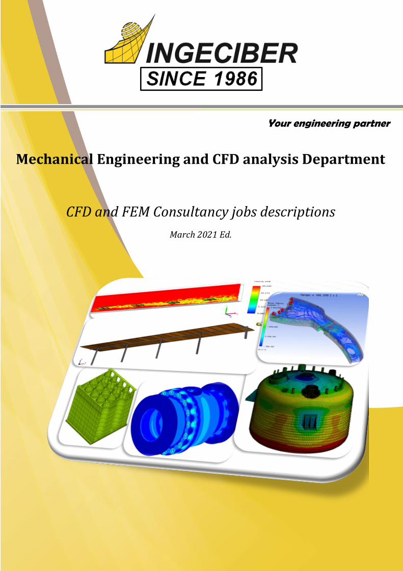
MAJOR COSTUMERS:

Your Engineering Partner Since 1986
2. CONSULTANCY JOBS DESCRIPTION & PROJECT´S REFERENCE
Mechanical Engineering Department
•Supports & Frameworks
•Outstanding Structures
•Machinery's specific components
•Linear & non-linear buckling
•Fatigue analysis
•Blast furnace components analysis
•Industrial plant components analysis following regulatory compliance
•Maximun stresses analysis following ASME VIII Div. 2
•Fatigue analysis following ASME VIII Div. 2
•Análisis de Uniones Faldón Envolvente.
•Thermal exchanger, aircooler and condenser analysis
•Pressure Vessels
•Analysis following regulatory compliance (RCC-MR, EN-13445, etc.)
Mechanic analysis
•Non linear materials (plascity, hiperelasticity, etc.)
•Structural inestabilities (non linear buckling)
•frinction and frictionless contacts between components
•Geometric non linear analysis
•Composites
•Bolt analysis
Non linear analysis
•Modal analysis
•Armonic analysis
•Lineal and non linear transient analysis
•Spectrum analysis
•Free vibration analysys (PSD)
•Rotordynamic
Dynamic analysis
•Themal isolation analysis of Pipes
•Thermal isolation design of train black boxes: Outstanding solutions.
•Thermal cycle simulations in air cooling systems for automotive industry.
•Testing storage design for disipation system and material properties characterization.
•Thermal analysis of valves.
•Fire fighting door thermal-structural analysis.
• Electric refrigeration (CFD analysis)
•Thermal analysis of cryogenic systems
Thermanl and CFD analysis
•Reactances.
•Permanent magnets.
•Coils, Induction engines
•Conductors, Wires.
Electromagnetic analysis

Your Engineering Partner Since 1986
Support analysis • Highest loads supported
• Thickness estimate
• Design validation
• Cross section validation
Framework analysis • Highest loads supported
• Thickness estimate
• Design validation
• Verification with UNE-EN 12663
• Tensile-compresive calculation
Outstanding structures • Design validation
• Verification with building norms
• Last state analysis
• Opening process
• Checked with wind-tunnel results
Mechanical analysis

Your Engineering Partner Since 1986
Non-linear analysis • Plasticity
• Hiperelasticity
• Composites
• Plastic deformations analysis
• Limit load analysis
• Hertz contacts
Linear & non-linear buckling
• Structural instability analysis
• Limit load in lineal buckling analysis
• Buckling Eigenvalues & Eigenvectors
• Non-linear buckling load estimate
Pretension bolts •Bolt dimensioning
•Pretension loads analysis
•Sequential pretension analysis (various bolts)
•Gasket analysis
•Bridle verification
Non-linear analysis

Your Engineering Partner Since 1986
Modal analysis
• Eigenvectors & Eigenvalues
• Modal deformed shape
• Participation factors
• Mass involved with each mode
• Prestressed modal analysis
Seismic design criteria • Spectral analysis
• Seismic design criteria of Extraction Bombs, Furnaces, Pressure Vessels,
Nuclear vessels, Structures, etc.
Dynamic analysis

Maximun stresses analysis following ASME
VIII Div. 2
• Maximun membrane and & membrane+bending stress analysis
following ASME
• Load combinations following ASME
• Thickness verification and reinforcement design following ASME
Fatigue analysis following ASME VIII Div. 2
• Fatigue verification following recomended ASME VIII procedure
• Load combinations following ASME
• Thickness verification and reinforcement design following ASME
• Cumulative fatigue usage analysis
Vessel to skirt joint analysis
• Maximun stress verification following ASME VIII
• Fatigue analysis following ASME VIII recomended procedure
• Load combinations following ASME
• Thickness verification and reinforce design
Specific norm analysis

10
Your Engineering Partner
Thermal exchangers • Maximun stress verification following ASME VIII
• Fatigue analysis following ASME VIII recomended procedure
• Load combinatons following ASME
• Thermal analysis
• Thickness verification
• Tubular shells validation
Analysis following specific norms • Maximun stresses verification following specific norms:
RCC-MR, EN-13445, etc.
• Load combinations
• Thermal analysis
• Thickness verification
• Reinforce design
• Hydraulic pressure tests
• Outstanding structures
11
Your Engineering Partner
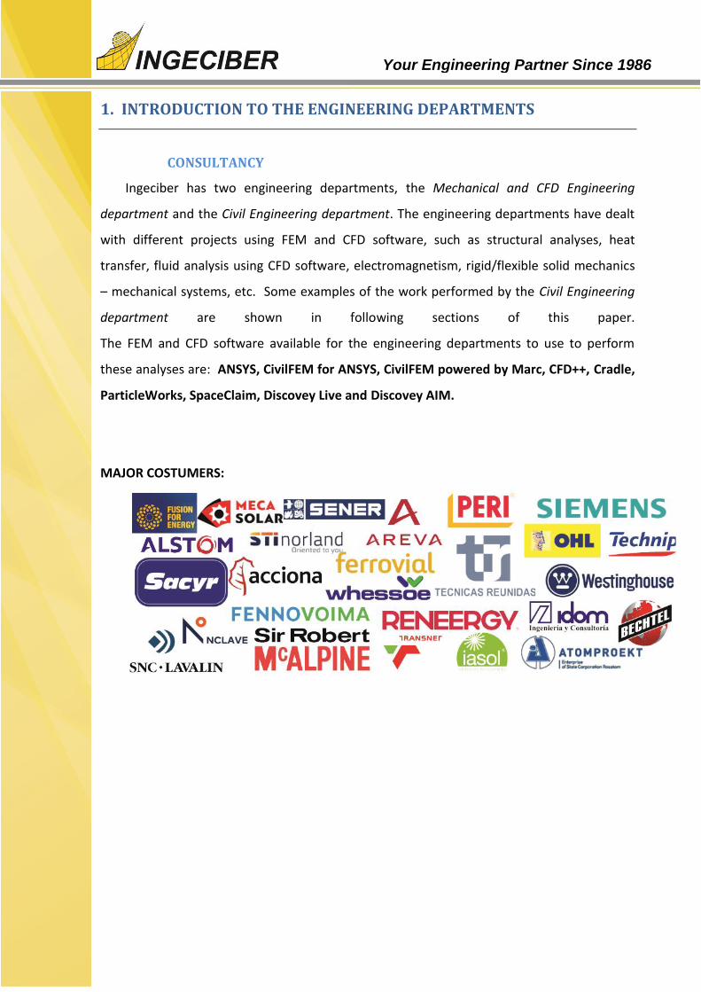
• Thermal isolation optimization. Low & high temperatures. Material properties temperature dependent.
• Analysis of thermal stresses
• Thermal isolation of furnaces and pipes
• Thermal isolation of tubes and anchoring for cryogenc systems
• Thermal analysis of cryogenic processors
• Thermal design of train's black boxes (phase change).
• Thermal cycle simulations at industrial components. Thermal stresses.
• Radiator analysis. Air-cooling for automotive industry.
• Testing storage design for disipation system and material properties characterization.
• Losses analysis
• Thermal disipation analysis in electric systems.
• Fluid-structure interaction.
• Industrial thermal exchanger analysis. CFD analysis.
• Fluid mixing analysis.
• Pipe pressure loss.
Thermal & CFD analysis

12
Your Engineering Partner
Reactances • Harmonic currents
• Eddy currents
• Losses
• Obtaining B & H fields
• Non-linear analysis (B-H curve)
• Thermal analysis
• Joule Heat
• Lorentz forces
Permanent magnets
• Coercitivity
• 2D & 3D analysis
• Vector potential analysis
• B & H fields
• Ferromagnetic materials
Cable & Conductors
• Harmonic currents
• Different materials (Steel, Al, etc)
• Skin effect
• Joule heat
• Thermal analysis
• B & H fields
Electromagnetic analysis

13
Your Engineering Partner
CFD STUDY OF A STORAGE AND PUMPING POOL
A deflector wall was placed at the entrance of a
sea water storage and pumping pool. To
homogenize the flux, two apertures were created
in the sides of the inflow catchment area. The
operation of the pool revealed a problem in the
bottom covering just in front of the lateral
apertures. The objective of the simulation was to
determine the causes of the failure and to
determine the optimum operation level to avoid
the lateral flux damaging the covering.
A sequence of CFD simulations with different
operation modes was proposed, varying only
the water level on the pool. The water level
determines the mass of water in the inflow
catchment area. Its interaction with the
incoming flux disturbs the proportion of
water which is alleviated through the lateral apertures and the velocity of this flux.
This study, which was performed
with ANSYS-CFX, allowed us to
understand the origin of the
problem detected and to define the
optimum water level to guarantee
the correct hydraulic behavior of
the pool.

14
Your Engineering Partner
Phases:
Generation of three-dimensional geometric model of the large pitcher and boxes of
bombs.
Domain fluid extraction study.
Domain meshing with refinement of boundary layer.
Preparation of multiple technical solutions with different deflector walls
Definition of the boundary conditions which simulate the different operation modes.
Results comparison.
Design optimization of the deflector wall.
Validation of the solution adopted verifying its behavior in all modes of operation.
CFD - DESIGN OF A DEFLECTOR WALL IN A PUMPS HOUSE
The modification of the mode of operation in a house of pumps is projected. The adding
of a pump modify the flow established in the large pitcher and turbulence arising are
sucked by the pumps compromising its operation.
.
A CFD simulation is planned with a three-
dimensional model showing the flow
behavior of the water in the pump
housing and the different options for a
deflector wall to optimize the overall
performance, considering the various
modes of operation raises the large
pitcher and boxes of bombs.
The results show how a small change in
the length of the wall or on exit angle,
alters the flow behavior across the large
pitcher. After several iterations in the
design process and analysis, the design
of the baffle wall is optimized.

15
Your Engineering Partner
CFD VIBRATION ANALYSIS OF A HOWELL-BUNGER VALVE INSTALLED AT A DAM
The goal of this study is to analyze using CFD techniques the hydraulic working of the
Howell-Bunger valve placed at the Aguilar de Campoo (Palencia, Spain) Dam, which is
subjected to unusual vibrations.
Three phases:
Phase 1: Study of the actual configuration of the pipe and the valve
Phase 2: Study of the pipe with some correcting measures (guides)
Phase 3: Optimization of the installation place of the guides
Guides installed in the pipe
Turbulences on the pipe
Pipe schema. The valve is placed at the outflow
16
Your Engineering Partner
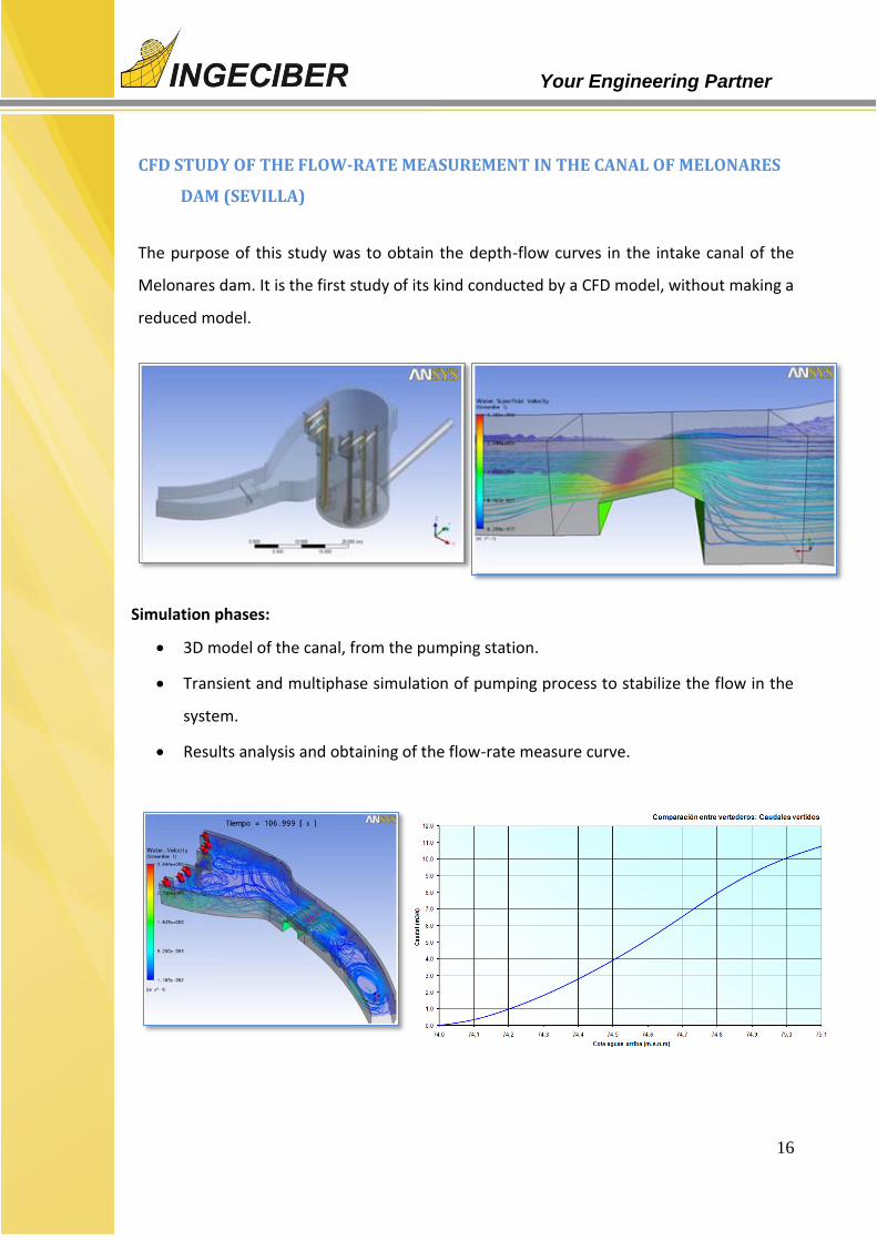
CFD STUDY OF THE FLOW-RATE MEASUREMENT IN THE CANAL OF MELONARES
DAM (SEVILLA)
The purpose of this study was to obtain the depth-flow curves in the intake canal of the
Melonares dam. It is the first study of its kind conducted by a CFD model, without making a
reduced model.
Simulation phases:
3D model of the canal, from the pumping station.
Transient and multiphase simulation of pumping process to stabilize the flow in the
system.
Results analysis and obtaining of the flow-rate measure curve.

17
Your Engineering Partner
FEM STUDY OF THE DAM DO BAIXO SABOR (PORTUGAL)
The dam do Baixo Sabor is an arch dam placed
on the north of Portugal. It is a tall structure in
which is necessary to analyze the concrete
temperature evolution during the construction
considering different cooling and environmental
hypothesis (cool water, river water or both).
The cooling system consists of the
arrangement of coils. The purpose of this
study was to dimension the cooling system.
A thermal transient and evolution calculation was performed taking as reference the
values of the permissible thermal indicators proposed in the Technic Guide nº 2 of the
Spanish Committee of large dams.
Thermal gradient in one of the phases of construction

18
Your Engineering Partner
CFD STUDY OF CHANNELING INFRASTRUCTURE
The predicted works for the
channeling of the water in
Argamasilla ravine included
different secondary streams. The
aim of the channeling is to alleviate
the constant floods that regularly
affect the city of Écija (Sevilla).
The 2D simulation didn’t allow us
to tackle the complete channeling
analysis. Furthermore, it was
necessary to analyze the transient
evolution of the incoming flood and
not assume a steady state flow. For
this reason, a tridimensional study
of the incoming flood was modeled
with ANSYS-CFX, taking into
account the elevated water level in
the Genil River, which is where the
simulated channeling flows into.
The simulation shows the behavior of the flood in a transient regime, with a return
period of 50 years in the last section of the Argamasilla ravine channeling. The results
showed that the initially projected solution did not take into account the behavior of the
flood at the initial moment. When the flood finds its outlet blocked by the Genil River,
the water impacts against the upper wall and emerges through the upper ventilation
grids, creating a water jump which returns back through the internal part of the duct.
This study and its results were used for the correct installation redesign.

19
Your Engineering Partner
CFD STUDY OF THE ADVANCE OF SEDIMENT PARTICLES DURING WASHING
PROCESS IN A STORM TANK
The construction of an underground storage tank for storm water is projected. A high
level of fouling due to sedimentation while water is stored is envisaged. To lower
maintenance costs, a washing process is designed without the direct action of
operators, consisting of a sudden emptying of a depot situated at the top of the tank,
hoping the current to pull out and drag the sediments deposited.
In the first phase is studied the flood process caused by the discharge of header tank
Transient flow simulation allows determining the hydrograph of the flood, which is
shown superimposed on the image. Known the induced trawling by the flood, is
discretized spatially and temporally the phenomenon of entrainment of particles and
quantified progress in each state of the flow of the flood. The results showed that the
sediments are dragged from the first half of the tank, but these are accumulating at the
back and a few leave the tank.
Phases:
Generation of geometric model.
Transient study of flood flux.
Discretized study of particles advance
Quantifying the degree of final advance of the particles along the storm tank.

20
Your Engineering Partner
CFD SIMULATION OF TWO FIXED EFFLUENT AND ANALYSIS OF THE DILUTION OF
ITS SALT CONTENT
Plants for desalination of sea water
pouring require the extracted salt treated
water. In this process, it is necessary to
control the final discharge salinity
lowering it by mixing it with seawater.
The mixture of effluent with seawater in
the same pipe is not enough to guarantee
the complete homogenization of salinity.
The objective is to simulate the mixing of
the effluent with sea water, taking into
account the geometry of the union and
the discharge pipe.
The analysis focuses on quantifying the evolution of salinity at each point of the pipeline. An added
difficulty is that the injection of the discharge
on the side of the pipe do not mix the two effluent because no turbulence is formed, and the
homogenization has to be produced by diffusion and stirring derived by the presence of bends in
the path of the pipe .
Simulation Phases:
3D model of a 250 m discharge pipe considering the blend placed at 50 m from injection
point.
Exhaustive meshing of the fluid domain with hexahedral elements that allow the
collection of all the details of the salt diffusion.
Application of models of particle concentration and diffusivity models.
Multiple simulations applying different salt concentrations and flow rates to
represent the different operating modes.
Analysis and quantification of mixed homogenization of salinity in the final
discharge

21
Your Engineering Partner
CFD SIMULATION A SPILL FROM A SUBMARINE OUTFALL
The objective of this study is to
monitor the spill of sewage
water from a submarine outfall
to the ocean. This type of study
is very important for complying
with the environmental
regulation.
A model of the shore with the
submarine outfall is created. Due
to the difficulty of anticipating the
spill behavior a big domain was
simulated. The adaptive
refinement of the software XFlow
allows controlling this type of
domain without wasting
computational resources. Scalar transport equations were used for the simulation and
monitoring of the spill.
An environmental regulation
was considered, checking the
maximum fraction of sewage
water at a distance from the
outlet of the submarine
outfall. With a spherical limit
surface it was checked the
position of the isosurface of
maximum fraction allowed by the environmental regulation.

22
Your Engineering Partner
FEM ANALYSIS OF AN OIL/SALT HEAT EXCHANGER
This project is the analysis of hot oil to molten salt heat exchanger located in Morocco
after several heat exchanger welds installed at the Solar Power Station have failed. The
design of this heat exchanger, focusing in the failure area, is analyzed by ANSYS by the
Finite Element Method (FEM) under the design and operation conditions defined by the
client, studying the results with the ASME VIII Div2 code.
Three different cases have been studied:
- The equipment design successfully fulfills the ASME code stress linearization criteria.

23
Your Engineering Partner
-A transient simulation has been performed. A stress maximum has been measured at the
critical weld for an intermediate time (due to the temperature drop between cavities).
-A fatigue case, considering salts loading and unloading. The maximum stress increment at
the critical weld has been measured for an intermediate time (due to the temperature
drop between cavities). Following the ASME code the equivalent stress has been obtained
and introduced in the S-N curve. A total of 15.7·106 cycles has been obtained under fatigue
at the critical weld, being higher than the minimum number of cycles defined by the client
(22000 cycles).
It can be concluded that the critical zone of the heat exchanger has been designed
correctly under the defined loads considering the stress and fatigue criteria of the ASME
code.

24
Your Engineering Partner
FLOW AND AERATION CFD STUDY IN A WWTP REACTOR
The design of a reactor of a Waste Water Treatment Plant (WWTP) has to focus towards a
uniform movement of sludge to prevent formation of prone to sedimentation and proper
aeration dead zones to encourage aerobic digestion of organic wastes. A design raised in
carousel reactor with an aeration system consisting of surface aerators, is expected that
the surface agitation of the sludge allow enter enough air into the device.
Phases:
Generation of three-dimensional geometric model of the WWTP reactor with
flowing accelerators and surface shakers.
Fluid domain extraction, establish boundary conditions and fluids provided for
installation devices.
As a result the flow characteristics established and dragging the oxygen introduced by
surface shakers shown. Aeration is very localized and insufficient, because below the
surface there are shakers much of the flow is not aerated.
Following this study finding alternative was approved for a more effective aeration.
25
Your Engineering Partner
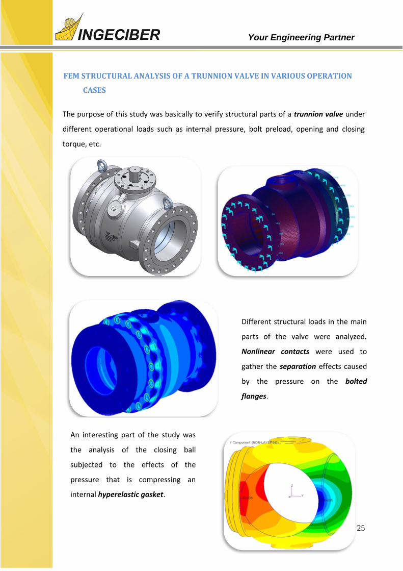
FEM STRUCTURAL ANALYSIS OF A TRUNNION VALVE IN VARIOUS OPERATION
CASES
The purpose of this study was basically to verify structural parts of a trunnion valve under
different operational loads such as internal pressure, bolt preload, opening and closing
torque, etc.
Different structural loads in the main
parts of the valve were analyzed.
Nonlinear contacts were used to
gather the separation effects caused
by the pressure on the bolted
flanges.
An interesting part of the study was
the analysis of the closing ball
subjected to the effects of the
pressure that is compressing an
internal hyperelastic gasket.
26
Your Engineering Partner
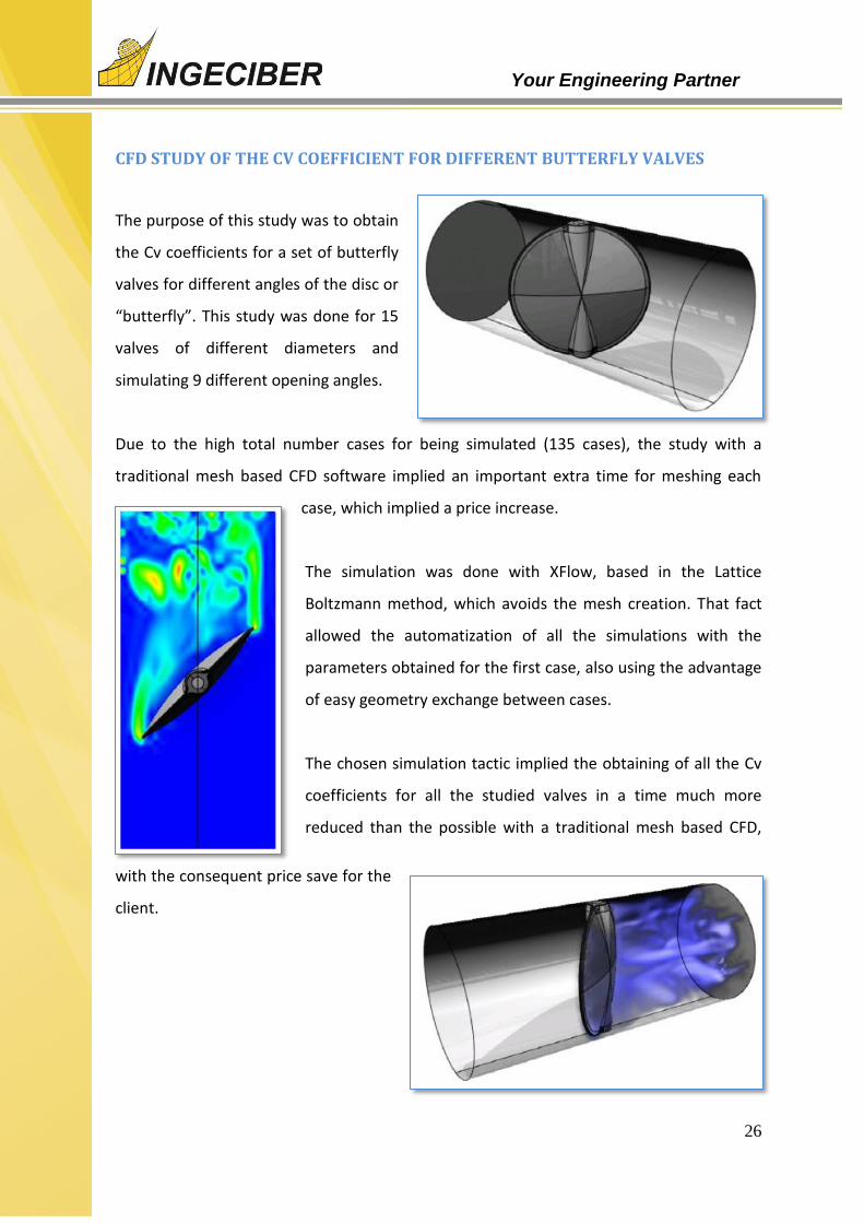
CFD STUDY OF THE CV COEFFICIENT FOR DIFFERENT BUTTERFLY VALVES
The purpose of this study was to obtain
the Cv coefficients for a set of butterfly
valves for different angles of the disc or
“butterfly”. This study was done for 15
valves of different diameters and
simulating 9 different opening angles.
Due to the high total number cases for being simulated (135 cases), the study with a
traditional mesh based CFD software implied an important extra time for meshing each
case, which implied a price increase.
The simulation was done with XFlow, based in the Lattice
Boltzmann method, which avoids the mesh creation. That fact
allowed the automatization of all the simulations with the
parameters obtained for the first case, also using the advantage
of easy geometry exchange between cases.
The chosen simulation tactic implied the obtaining of all the Cv
coefficients for all the studied valves in a time much more
reduced than the possible with a traditional mesh based CFD,
with the consequent price save for the
client.
27
Your Engineering Partner
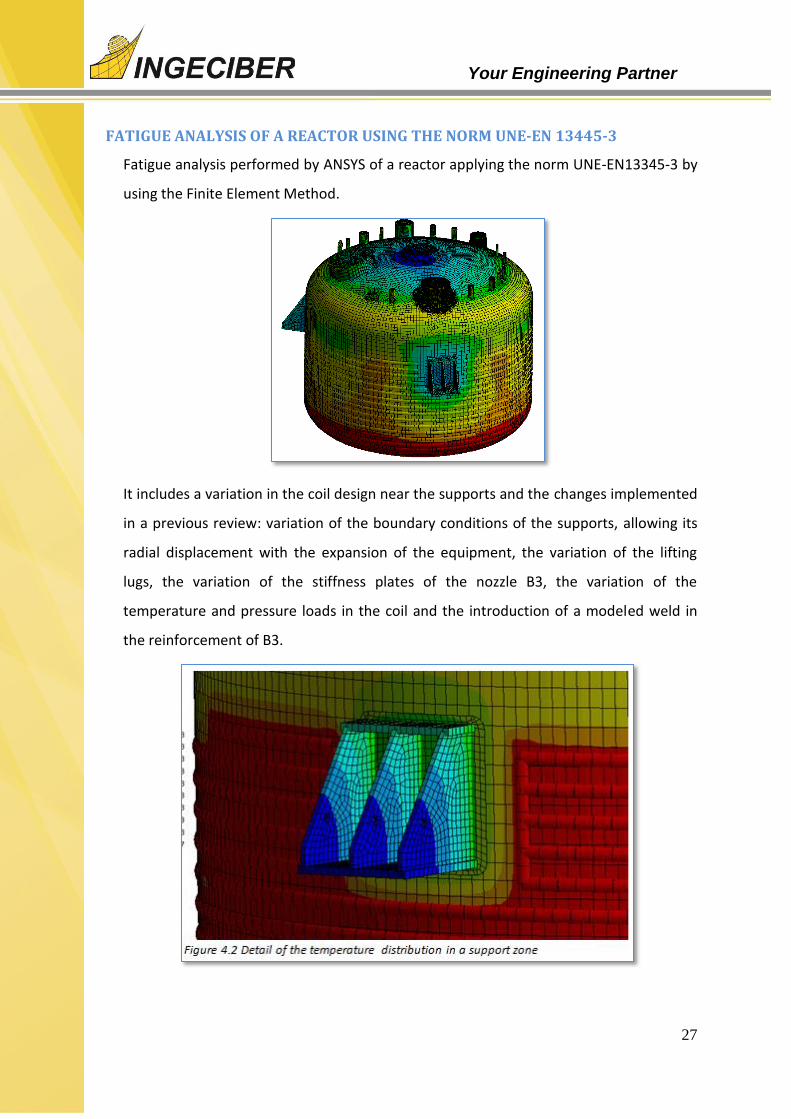
FATIGUE ANALYSIS OF A REACTOR USING THE NORM UNE-EN 13445-3
Fatigue analysis performed by ANSYS of a reactor applying the norm UNE-EN13345-3 by
using the Finite Element Method.
It includes a variation in the coil design near the supports and the changes implemented
in a previous review: variation of the boundary conditions of the supports, allowing its
radial displacement with the expansion of the equipment, the variation of the lifting
lugs, the variation of the stiffness plates of the nozzle B3, the variation of the
temperature and pressure loads in the coil and the introduction of a modeled weld in
the reinforcement of B3.

28
Your Engineering Partner

29
Your Engineering Partner
FEM STRUCTURAL ANALYSIS OF A FLOATING CAISSON ( BREAK WATER)
A 3D concrete floating voided caisson is modeled in order to optimize the thickness of
the concrete elements and reinforcement amount. Different calculation models are
studied for each stage: transport, positioning, immersion and service.
The loads taken into account and the combined for ultimate and serviceability limit
state are the ones considering all stages including pressures due to immersed caisson
(ballasted with water or with sand) .

30
Your Engineering Partner
CFD FIRE SIMULATION IN M-30 TUNNELS (MADRID)
M-30 is composed of two parallel underground tunnels over 50 meters that withstand a
huge transit of vehicles.
Ventilation inside the structure and proper evacuation of the smoke from a possible fire
proved vital.
The following calculations were made:
Simulation phases:
3D modelling of the ventilation system.
Transient simulation with variation of pulse energies and extraction based on
the evolution of the fire.
Smoke spread simulation.
Analysis of results and corrective actions.

31
Your Engineering Partner
CFD SIMULATION OF THE SMOKE TRANSMISSION IN A SUBWAY STATION
The aim of this transient CFD analysis is to study the transmission of the smoke inside a
subway station due to the fire produced in a train. This type of study is very important
inside the security studies which must
be done during the design phase of
the station.
Scalar transport equations were used
for simulating the smoke, being its
movement governed by the
buoyancy effects due to the
differences of temperature and
density.
During the study the quantity of
smoke was monitored in the exits
and other points of the station. With
these results it was checked which
were the escape routes in which the
smoke maximum value was produced before.
This study showed the need of applying extra security measures in some routes of the
design to avoid the fast concentration of smoke.

32
Your Engineering Partner
CFD - WIND ACTION IN A WIND TURBINE FIELD
The aerodynamic behavior of a wind turbine field is conditioned by the adjacent terrain.
The register of the wind in the zone is limited
and the wind tunnel studies do not capture the
orography characteristics with the presence of
moving wind turbines.
To obtain more accurate and realistic results,
tackling the study with computational fluid
dynamics (CFD) techniques was proposed. The
conventional software with their traditional
approach, based on the finite volumes method,
are not sufficient to accurately study such a big
domain with the presence of wind turbines in
movement.
The software used was XFlow, with the
assistance and knowledge of the Mechanical
Engineering and CFD Department.
The topographic surface of the area was
introduced in the software and the 28 wind
turbines which form the wind turbine field
were placed accurately. The extension of the
terrain studied was 432 km2. The rotation
degree of freedom of the blades was allowed
and the wind was defined with a real wind profile of the area. The adaptive refinement
of the lattice allowed the capture of the movement of the blades and their influence on
the wind distribution.

33
Your Engineering Partner
FOUNDATION REPAIR FEM CHECKING OF WIND TURBINES
Foundation repair checking of wind turbines in Pedregoso wind park.
The study is focused in the foundation critic zones checking. These areas are more
susceptible to damage. This study put the focus on the part of the original foundation
where the active bars are anchored guarantying the union between the design repair
and the existing foundation.
These results are compared with the repair-less foundations, with the goal of
determining their ultimate load and the necessity of being repaired or improved.
An static and nonlinear FE model of the existent foundation has been modeled
corresponding to a standard wind turbine. This model takes into account the repair
proposed by the customer with the different load cases acting on the structure.

34
Your Engineering Partner
FEM ANALYSIS AND DESIGN OF A TURBINE FOUNDATION
Object
• Analysis and Design of Turbine Foundation
Calculations Steps
Model used for dynamic analysis is taken for static analysis
Material properties (concrete , steel) , real constants, codes to be used (EUROCODES, ACI,
etc.) are specified in CivilFEM
Various load steps are specified in ANSYS and the load combinations done in CivilFEM
Reinforcement design using CEB Code method
Envelope of reinforcement design results over various load steps obtained (contour plots
and listing is possible)
Design optimization and shear check
35
Your Engineering Partner
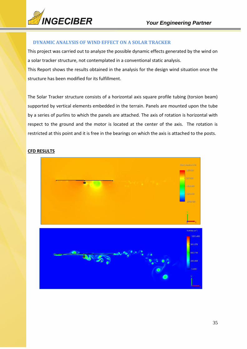
DYNAMIC ANALYSIS OF WIND EFFECT ON A SOLAR TRACKER
This project was carried out to analyze the possible dynamic effects generated by the wind on
a solar tracker structure, not contemplated in a conventional static analysis.
This Report shows the results obtained in the analysis for the design wind situation once the
structure has been modified for its fulfillment.
The Solar Tracker structure consists of a horizontal axis square profile tubing (torsion beam)
supported by vertical elements embedded in the terrain. Panels are mounted upon the tube
by a series of purlins to which the panels are attached. The axis of rotation is horizontal with
respect to the ground and the motor is located at the center of the axis. The rotation is
restricted at this point and it is free in the bearings on which the axis is attached to the posts.
CFD RESULTS

36
Your Engineering Partner
FINITE ELEMENT TRANSIENT ANALYSIS

37
Your Engineering Partner
After obtaining the first results of dynamic effects due to the interaction between the wind and the panel (angles and frequencies), the moments generated in the central tube were applied from these results.
From the transient analysis of the FEM model of the structure, the performance over time of the tracker's structure is calculated, obtaining the maximum tension and moment that they have during the first seconds.

38
Your Engineering Partner
BOILER BURNER COMBUSTION CFD ANALYSIS
Finite volume analysis of the inlet flow behavior of a boiler with four burners. The air distribution between the four burners and its distribution in the different inlet sections of the boiler will be analysed.
Geometry: Velocity field in the plane z=-0.064:
Velocity field in the plane z=0.177. Detail of burner 3 with vectors:

39
Your Engineering Partner
Velocity field in the x=2.93 plane. Burners 1 and 2:
Percentage deviation from the mean flow of the annular inlet sections in burner 1:

40
Your Engineering Partner
AERODINAMIC STUDY (CFD) OF AN AIRCRAFT
Aircraft´s Airflow dynamics analysis using finite volume Computational Fluid Dynamics
(CFD) tools. The forces and moments generated by the aerodynamic profiles of the
different surfaces as well as the effect of the pressure and speed fields were analysed.
Software used: CFD++
Turbulence: Ratio of turbulent viscosity to laminar viscosity in the plane of symmetry(y=0)
Speed: Velocity field in the plane of symmetry (y=0)
Pressures: Pressure field in the plane of symmetry (y=0):

41
Your Engineering Partner
CFD - WIND ACTION ON A SOLAR PLANT
Solar panels that make up a
solar plant are exposed to
weather actions, among which
are the strong winds that occur
occasionally. This was the case
of the solar garden in Vejer de la
Frontera, which in April 2011
suffered damage due to the
wind.
The case of study is the wind
around the solar array so that
checkpoints where
anemometers are placed get the
same values than those
observed in both speed and
wind direction. In this situation,
the wind speed on the exact
location of the solar plant and
solar panels affected is analyzed.
The results show that the surrounding orography alters the behavior of the wind and when the
conditions observed in April 2011 are reproduce , the solar farm area is swept by winds of over
115 km / h, which exceeds the design strength panels.
Phases:
Generation of three-dimensional geometric model of the terrain in the area of solar plant.
Imposition of boundary conditions that define the observed wind and verification by
sensors placed on the position of the reference anemometers.
42
Your Engineering Partner
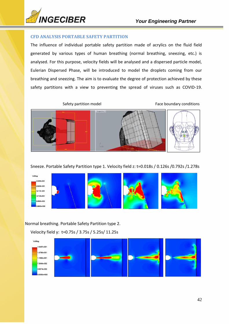
CFD ANALYSIS PORTABLE SAFETY PARTITION
The influence of individual portable safety partition made of acrylics on the fluid field
generated by various types of human breathing (normal breathing, sneezing, etc.) is
analysed. For this purpose, velocity fields will be analysed and a dispersed particle model,
Eulerian Dispersed Phase, will be introduced to model the droplets coming from our
breathing and sneezing. The aim is to evaluate the degree of protection achieved by these
safety partitions with a view to preventing the spread of viruses such as COVID-19.
Safety partition model Face boundary conditions
Sneeze. Portable Safety Partition type 1. Velocity field z: t=0.018s / 0.126s /0.792s /1.278s
Normal breathing. Portable Safety Partition type 2.
Velocity field y: t=0.75s / 3.75s / 5.25s/ 11.25s

43
Your Engineering Partner
CFD ANALYSIS OF WIND EFFECT ON AN HELIOSTAT
The design and dimensioning of
equipment exposed to wind actions
requires a thorough aerodynamic
analysis. In the case of a heliostat, the
large size of the mirror determines its
wind resistance.
To address this analysis in time and
reasonable price, the best option is the
three-dimensional simulation using CFD
programs. Two situations were simulated:
the mirror in a vertical position subjected
to a wind of 100 km/h, and the mirror in
the safety position under a wind of 150
km/h.
Data of the drag, the tilting in the column
base, and lift force and torque turning of
the upper joint is obtained. These latest
actions come from the deflection of the
air flow when the mirror is folded.
Phases:
Adequacy of generating three-dimensional geometry and fluid surrounding the heliostat
domain.
Meshing of the fluid domain with special caution in the details of geometry and elements
of the boundary layer. The final calculation mesh consists of 22 million elements.
Definition of wind action conditions.
Resolution of the simulation and monitoring of the resultant forces.
Analysis of results and conclusions
44
Your Engineering Partner
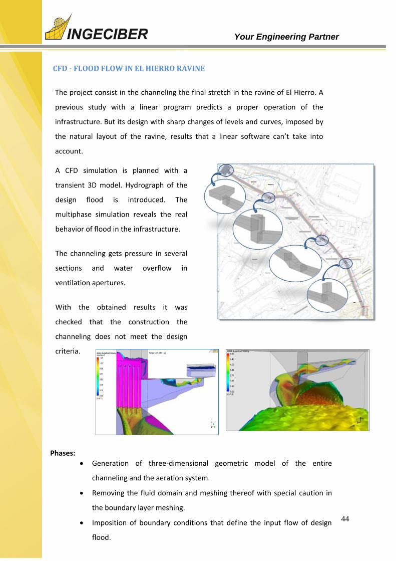
CFD - FLOOD FLOW IN EL HIERRO RAVINE
The project consist in the channeling the final stretch in the ravine of El Hierro. A
previous study with a linear program predicts a proper operation of the
infrastructure. But its design with sharp changes of levels and curves, imposed by
the natural layout of the ravine, results that a linear software can’t take into
account.
A CFD simulation is planned with a
transient 3D model. Hydrograph of the
design flood is introduced. The
multiphase simulation reveals the real
behavior of flood in the infrastructure.
The channeling gets pressure in several
sections and water overflow in
ventilation apertures.
With the obtained results it was
checked that the construction the
channeling does not meet the design
criteria.
Phases:
Generation of three-dimensional geometric model of the entire
channeling and the aeration system.
Removing the fluid domain and meshing thereof with special caution in
the boundary layer meshing.
Imposition of boundary conditions that define the input flow of design
flood.

45
Your Engineering Partner
CFD - WAVE INFILTRATION STUDY THROUGH A SEA DIKE
The design and dimensioning of a sea dike to protect an artificial platform requires a
stability study, overtopping waves and infiltration inside. To address this analysis in time
and reasonable price, the best option is the simulation using CFD programs.
Every detail of the different layers that make up the dike was introduced into the
program, each characterized by its porosity and permeability. An area of open sea 300
meters long was generated and was coupled to the dike so that the water flows
therein.
Simulations show the behavior of the waves in the sea, where the waves break by
their interaction with the seabed, and the impact thereof on the dam and the
subsequent infiltration. The results allow to analyze the behavior of infiltration and
saturation evolution of the different layers and the groundwater.
Phases:
2D model of the different layers of the dike and 300m stretch of sea.
Meshing of porous domains that form the dike and meticulous hexahedral
meshing of the fluid domain that represents the extent of open sea with
waves.
Definition of the groundwater level and transient generation of waves.
Resolution of the simulation and monitoring of the evolution of the water
table.
Obtained results analysis. Conclusions.

46
Your Engineering Partner
FEM VIBRATIONAL ANALYSIS CRYOPLANT BUILDING ITER. FUSION FOR ENERGY
The project consists in the vibration analysis in
an ITER´s plant building produced by a set of
rotative machines (compressors) for the final
customer Fusion For Energy. The objective was
to verify that the maximum amplitude of
vibration in a range of frequencies was not over
an allowable value for all the structural parts of
the building.
As shown in the image at the left the stratum
composed by rock (pink), soil (blue) and
compacted fill (red) was modeled.
The amplitude of displacements,
accelerations and velocities in critical
measure points of the building where
checked along the working frequency range
of the rotative machines.
criteria.

47
Your Engineering Partner
CFD ANALYSIS OF THE EVOLUTION OF AN EXPLOSION'S EXPANSIVE WAVE
The structural design of a building in an oil & gas plant has to take into account the
dynamic behavior of the building due to an expansive wave produced by a near
explosion.
The analysts have to measure the building to satisfy the codes. The critic point is to
know the time evolution of the over pressure pulses and the places of the building more
exposed.

48
Your Engineering Partner
3. ADDITIONAL INFORMATION - SOCIAL NETWORKS
More information about the different business lines of Ingeciber is available at the websites
shown below:
o Ingeciber website: www.ingeciber.com
o Youtube Channel: Youtube channel
o CivilFEM website: www.civilfem.com
o Int’l UNED-Ingeciber FEA Master’s: www.uned.es/mastermef
o Int’l online CAE Education CENTER: www.icaeec.com
o Ingeciber Linkedin: https://www.linkedin.com/company/ingeciber
o Ingeciber Twitter: @Ingeciber. https://twitter.com/Ingeciber
o Facebook: www.facebook.com/ingeciber/
o ANSYS Preferred partner: https://www.ansys.com/about-ansys/partner-
ecosystem/software-partners/ingeciber