Embed Size (px)
Citation preview
MECHANICAL, ELECTRICAL, AND PLUMBING SPECIFICATIONS for
PHYSICAL THERAPY AND REHABILITATION RENOVATION Christus Hospital St. Elizabeth
Park Med II Beaumont, Texas
MECHANICAL AND PLUMBING SPECIFICATIONS 15010 – GENERAL MECHANICAL REQUIREMENTS 15011 – SUPPORTS, SLEEVES AND HANGERS 15012 – VALVES 15014 – TRENCHING AND BACKFILLING 15021 – CORRECTIONS AND MAINTENANCE DURING THE WARRANTY PERIOD 15025 – OWNERS OPERATING AND MAINTENANCE MANUALS 15030 – MECHANICAL SYSTEMS TESTING AND BALANCING 15031 – COORDINATION OF TESTING AND BALANCING 15040 – SHOP DRAWINGS AND PRODUCT DATA (SUBMITTALS) 15041 – PROJECT RECORD DOCUMENTS 15200 – SOUND AND VIBRATION CONTROL 15255 – PLUMBING SYSTEMS PIPING INSULATION 15260 – DUCTWORK INSULATION 15410 – PLUMBING PIPING SYSTEMS 15420 – PLUMBING EQUIPMENT 15430 – PLUMBING FIXTURES AND TRIM 15800 – DUCTWORK SYSTEMS 15802 – AIR GRILLES, REGISTERS AND DIFFUSERS 15803 – AIR CONTROL DAMPERS 15841 – VENTILATION AND EXHAUST SYSTEMS 15880 – AIR FILTERS
ELECTRICAL SPECIFICATIONS 16010 – GENERAL ELECTRICAL REQUIREMENTS 16011 – SUPPORTS, SLEEVES, FASTENERS AND HANGERS 16014 – TRENCHING AND BACKFILLING 16021 – CORRECTIONS AND ROUTINE MAINTENANCE DURING WARRANTY
PERIOD 16025 – OWNERS MANUALS 16027 – ELECTRICAL SYSTEMS AND EQUIPMENT IDENTIFICATION 16030 – ELECTRICAL SYSTEMS TESTING 16040 – SHOP DRAWINGS AND PRODUCT DATA (SUBMITTALS) 16041 – PROJECT RECORD DOCUMENTS 16090 – CONDUCTOR SYSTEMS - 600 VOLT RATING 16100 – CONDUIT SYSTEMS 16103 – GROUNDING OF ELECTRICAL SYSTEMS 16130 – SURFACE RACEWAYS 16131 – PULL BOXES AND JUNCTION BOXES 16132 – FLOOR BOXES 16140 – WIRING DEVICES 16510 – LIGHT FIXTURES AND LAMPS 16625 – EMERGENCY BATTERY POWERED LIGHTING 16740 – COMMUNICATION CONDUIT SYSTEM

SECTION 15010
15010.1
GENERAL MECHANICAL REQUIREMENTS
1.01 REQUIRED CONTRACTOR QUALIFICATIONS
A. Be a specialist in this field, having the organization to provide trained, experienced and
skilled personnel required to construct a practical working system.
B. Be able to provide evidence of having contracted for and installed systems of comparable
size and type to the systems specified herein.
1. Systems submitted as previous experience shall have served their Owners
satisfactorily for not less than 3 years.
1.02 RELATION WITH OTHER TRADES
A. Study all matters and conditions of the Project and relations to all divisions of work.
1. Cooperate and coordinate with other divisions of work to provide a complete and
functioning system in accordance with the Project Documents.
2. Notify Architect/Engineer of conflicts in ample time to prevent unwarranted
changes in any work.
B. Provide coordination drawings of any and all systems necessary for coordination with
other divisions of work.
C. Request all shop drawings and product data in ample time to permit proper installation of
the systems and to prevent unwarranted delays in the Project construction schedule.
D. Stub up and protect open ends of pipe before any concrete is placed.
E. Coordinate sizes of required equipment pads. Coordinate and locate all bolts and fittings
required to be cast in them.
F. Refer to other Divisions of the specifications for the scope of required connections to
equipment furnished under that Division. Determine from the Contractors for the various
trades and by direction from the Architect/Engineer the exact location of all items. The
Contractors involved will furnish all roughing-in drawings and piping diagrams required
for proper installation of the mechanical work.
G. Coordinate electrical requirements of all mechanical equipment with Division 16.
1.03 MATERIALS AND WORKMANSHIP
SECTION 15010
15010.2
A. All materials and equipment shall be new and of best grade and quality, provided by
reputable manufacturers regularly engaged in the production of such materials and
equipment.
B. Work shall be executed and all materials installed in accordance with the best practice of
the trades in a thorough, workmanlike manner by competent workmen, presenting a neat
appearance when completed.
C. With exceptions as specified and/or indicated on the Drawings; install, connect, erect,
use, clean and condition manufactured articles, materials and equipment per
Manufacturer's current printed instructions and recommendations.
D. The design is based on the equipment scheduled. Items furnished by other Manufacturers
named in the Specifications shall have prior approval of the Architect/Engineer.
E. Materials and equipment shall be new and in good condition. The commercially standard
items of equipment, and the specified names mentioned herein are intended to identify
standards of quality and performance necessary for the proper functioning of the work.
Since manufacturing methods vary, reasonable minor variations are expected; however,
performance and material requirements are the minimum standard selections other than
those scheduled.
F. Continuously maintain quality control over supervision, sub-contractors, materials,
equipment and workmanship to produce work in accordance with the Contract
Documents.
1.04 FACTORY FINISHES
A. Factory assembled equipment (excluding plumbing fixtures, nonferrous or galvanized
items and other items specified or scheduled to have specific finish) shall be delivered
with a factory applied finish such as baked on machinery enamel which does not require
additional field painting.
B. Factory finishes that become marred, stained or otherwise damaged shall be restored.
C. Should any of the special factory applied coatings be damaged during handling, storage
or installation, the damaged areas shall be recoated in the field using the same surface
preparation and coating system originally applied by the manufacturer.
1.05 DELIVERY, STORAGE, AND HANDLING
A. Protect all materials and equipment to be installed under this Division from physical and
SECTION 15010
15010.3
weather damage. Work under this division shall include:
1. Shipping from point of manufacture to job site.
2. Storage on-site as required.
1.06 DRAWINGS AND SPECIFICATIONS
A. Mechanical Drawings are diagrammatic and shall be followed as closely as the actual
construction will permit.
B. Should changes in work be required to make work specified in this Division conform to
the Project as it is constructed or to make it conform with requirements of governing
Codes and authorities:
1. Submit request for direction before proceeding with work.
C. All changes due to poor workmanship and/or coordination shall be made without
additional expense to the Owner.
D. Relocation of equipment and systems installation of up to 3 feet both vertically and
horizontally from the position indicated on the drawings may be directed without
additional cost.
1.07 LOCATIONS AND ELEVATIONS OF UTILITIES
A. Locations and elevations of utilities indicated on the drawings have been obtained from
utility maps and other substantially reliable sources and are offered only as a general
guide for coordination, without guarantee as to accuracy.
B. Prior to excavation for new work, field verify all locations and elevations of utilities and
their relation to new work.
1.08 CODES, PERMITS, AND FEES
A. Comply with the most recent versions of all applicable laws, rules, regulations, and
ordinances of all governing Codes and Authorities.
B. Modifications required by the above said authorities shall be made without additional
charge to the Owner.
C. Where alterations to and deviations from the Contract Documents are required by said
authority, report the requirements and secure approval before starting work.
SECTION 15010
15010.4
D. Obtain all applicable permits and pay all fees charged by above authorities.
E. Where Contract Document requirements are in excess of code requirements and are
permitted under the code, the Contract Documents shall govern.
F. Coordinate with the various utility companies connections to utility mains.
1. Pay all costs for tap fees and installation of utilities under existing reads as
required by utility companies and all other governing authorities.
1.09 SUBMITTALS AND “AS-BUILT” DRAWINGS
A. Submit shop drawings, coordination drawings and product data for all materials and
equipment.
1. Where required in individual specification sections of the Division 15 series.
B. Employ the procedures of submittals processing as described in other Sections of the
Specifications.
C. Keep a record of all deviations from the construction documents. Prepare a complete set
of record drawings and prepare in a reproducible form for submission to the
Architect/Owner at the conclusion of the projects.
END OF SECTION
SECTION 15011
15011.1
SUPPORTS, SLEEVES AND HANGERS
1.01 GENERAL REQUIREMENTS
A. All equipment and piping shall be installed in a neat and workmanlike manner by skilled
mechanics having prior experience in installing such systems.
B. Adhere to the general routing of the piping systems as shown on drawings.
C. Coordinate exact location and routing of the piping systems with all elements of the
building construction to avoid conflicts with use of building space.
D. Install piping systems in the most direct manner, adjacent walls and structures to occupy
the minimum of space while maintaining adequate space and clearance for:
1. Installation of pipe insulation.
2. Adjustment of pipe hangers.
3. Access to valves and other appurtenances in the piping systems.
4. Expansion and contraction without stressing pipe, pipe joints and connections to
equipment.
E. Excessive vibration or noise levels in the piping systems caused by improper or
inadequate suspension, support or connection is not acceptable.
1.02 REFERENCE STANDARDS
A. MSS SP-89 Pipe Hangers and Supports - "FABRICATION AND INSTALLATION
PRACTICES".
B. MSS SP-89 Pipe Hangers and Supports - "MATERIALS, DESIGN and
MANUFACTURER".
1.03 PIPE HANGERS AND SUPPORTS
A. Install hangers and supports to provide a minimum of ½" between finished covering and
adjacent work.
B. Provide hangers within 12" of each horizontal elbow.
C. Support riser piping independently of connected horizontal piping.
D. Use hangers with minimum 1 ½" vertical adjustment.
E. Provide multiple or trapeze hangers where several pipes can be installed parallel and at
SECTION 15011
15011.2
same elevation.
1. Size hangers to accommodate electrical conduits where shown on the drawings.
F. Wall support - as noted and/or detailed on drawings.
G. Vertical support - steel riser clamp.
H. Horizontal support - as noted and/or detailed on drawing.
I. Trapeze hangers - galvanized steel channels or galvanized unistrut galvanized hanger
rods.
J. Copper pipe hangers - adjustable copper plated carbon steel ring sized for copper piping.
1. Sheet lead packing between hanger and piping may be used in-lieu-of copper
plated hangers.
1.04 PIPE SLEEVES AND ESCUTCHEONS
A. Provide sleeves:
1. Where piping penetrates concrete or masonry construction.
2. Where required to accommodate installation of piping after completion of other
work.
3. Where vibration, expansion and contraction may affect finished surfaces
penetrated by pipe.
4. All other places shown on the drawings.
B. Sleeves shall be adequately sized to allow for:
1. Application of the specified insulation types and thicknesses; continuous through
the sleeve.
2. Movement due to expansion and contraction.
C. Do not permit the pipe/pipe insulation to touch the wall of the sleeve.
D. Provide schedule 40 galvanized steel pipe sleeves flush with wall surfaces where piping
passes through exterior walls.
1. Seal annular space with butyl rubber sealant.
F. Provide schedule 40 galvanized steel pipe sleeves where piping passes thru non-fire rated
interior walls to deck.
1. Non-fire rated walls - pack annular space with l lb. density fiberglass insulation.
SECTION 15011
15011.3
F. Provide formed stainless steel or cast brass escutcheon plates where piping penetrations
are exposed to view on exterior wall surface and interior unoccupied spaces.
G. In finished interior spaces exposed to view, provide nickelbrass or chrome plated
escutcheons.
H. Secure all escutcheons to pipe with tamper-proof set screws.
1.05 GENERAL SECURING, SUPPORTING AND SUSPENDING OF PIPING AND
EQUIPMENT
A. Secure and suspend piping and equipment from the building structure by approved
hangers and supports, installed in a manner to prevent excessive stress and vibration
transmission.
B. Perforated strap is not approved as hanger material.
C. All components of the hanger and support assemblies to be electo-galvanized with
galvanized or cadmium plated threaded rods, nuts and hangers.
D. Fasten hanger rods to the building structure with beam fasteners compatible with
structural members and conditions.
E. Provide hanger rods sized as scheduled on the drawings.
F. Hanger types for pipe sizes as follows:
½" to 2" - malleable iron or carbon steel swivel, split ring type
½" to 6" - carbon steel, adjustable clevis
G. Where trapeze hangers are used to suspend multiple pipes; provide rods sized for largest
pipe on hanger.
H. Maximum horizontal single pipe support/hanger spacing
I. Where multiple pipes are suspended/supported on common hangers or supports; provide
spacing as required for smallest pipe on hanger/support.
J. Reference drawing details for additional support and hanger requirements.
SECTION 15011
15011.4
1.06 SUBMITTAL REQUIREMENTS
A. Submit special types of sleeves, escutcheons plates, hangers, supports, framing and
attachment methods where required for particular conditions.
END OF SECTION
SECTION 15012
15012.1
VALVES
1.01 GENERAL
A. All valve materials shall be suitable for the intended service.
B. Where possible, provide valves of the same manufacturer.
C. Provide valves with the manufacturer's name and pressure rating clearly marked on
outside of body.
D. Provide extended neck on all valves installed in the insulated piping systems as required
to allow the valve operator and stop plate to fully clear the insulation surface.
E. The pressure and temperature ratings of valves provided shall not be less than the design
criteria applicable to all components of the system.
F. Unless indicated otherwise, provide valves with ratings suitable for 125 minimum psig
and 450 degrees F and maximum 200 psig and 250 degrees F.
1.02 VALVE CONNECTIONS
A. Use pipe size valves suitable to connect to adjoining piping.
1. As specified for pipe joints.
B. Solder or screw to soldered adapters where installed in copper piping or tubing.
C. Solder or screw to adapters where installed in PVC piping.
D. Thread steel pipe sizes 2" and smaller.
E. Flange steel pipe sizes 2 ½" and larger.
1.03 VALVE OPERATORS
A. Provide all valves with suitable hand wheels.
B. When cocks and valves are provided with a square head stem, provide appropriate
wrench.
1. Provide wrench with set screw for cocks and valves 2 ½" and larger.
SECTION 15012
15012.2
C. Provide handles and operators for butterfly valves as indicated on the drawings.
1.04 INSTALLATION
A. Install gate valves to isolate/shut-off service to equipment, parts of systems and vertical
risers.
1. And as shown on the drawings.
B. Install with stem vertical or horizontal only.
C. Install valves in piping at locations accessible for service.
D. Install valves in accordance with the manufacturer's instructions.
E. Use butterfly and ball valves in hot and chilled water piping systems interchangeably in
place of gate and globe valves.
1.05 GATE AND GLOBE VALVES
A. Equipped with packing suitable for the intended service and designed for packing under
pressure.
B. When fully opened, the back seat shall protect the packing and stem threads from the
fluid.
C. Provided with a gland follower.
D. Provide solid wedge type gate valves designed so that seating surfaces do not contact
until near the point of closure.
1.06 BUTTERFLY VALVES
A. Conforming to MSS-SP-67
B. All components suitable for the intended service.
C. Full lug type body designed for installation between ANSI standard flanges.
SECTION 15012
15012.3
1.07 BALANCING VALVES
A. Provide with:
1. Permanently lubricated, corrosion resistant bearings.
2. Corrosion resistant plug and resilient seal.
3. O-ring stem seal.
B. Connections
1. Threaded up through 2" pipe size.
2. Flanged for 2 ½" pipe size and larger.
C. Provide each valve with a memory stop, plastic drip cap and 1/8" gauge tap.
1.08 BALL VALVES
A. Provide with:
1. Cast bronze body with threaded ends.
2. Full size port.
3. ASTM B16 brass ball.
4. Blowout proof stem.
B. All components suitable for the intended service
1.09 ACCEPTABLE MANUFACTURERS
A. POWELL
B. CRANE
C. WECO
D. DEZURIK
E. NIBCO
F. BRAY
G. APPROVED EQUAL
1.10 SUBMITTAL REQUIREMENTS
A. Submit a copy of the valve ordering schedule for review prior to ordering.
SECTION 15012
15012.4
B. Include the following information for each valve.
1. Manufacturer and model number.
2. Pressure rating.
3. Size and type.
4. Intended service.
5. Extended stem if installed in insulated piping systems.
END OF SECTION
15014.1
SECTION 15014
TRENCHING AND BACKFILLING 1.01 GENERAL
A. Stake out routing of the excavation by actual field measurements. B. Set required lines and levels. C. The Drawings indicate all known information related to existing surface and
sub-surface obstructions affecting the areas of work. This information is not guaranteed.
D. Notify Architect/Engineer of unexpected sub-surface conditions and discontinue work in affected area until notification to resume work.
1.02 UTILITIES
A. Prior to beginning excavation, locate all underground utilities occurring in work areas. 1. Request from the Owner any and all information on utilities not shown on
the Drawings. 2. Notify Architect/Engineer of unexpected utilities and conditions and
request direction prior to continuing work in affected areas. B. Maintain, extend or reroute all existing utilities required to remain and pass
through the work area. C. Do not disrupt or disconnect existing active utilities without proper
coordination and scheduling with the Architect, Engineer and Owner. D. Cap, plug or seal abandoned utilities in areas of excavation.
1. As shown on the Drawings. 2. As directed by the Architect/Engineer.
1.03 PROTECTION
A. Protect existing utilities during excavation. B. Grade excavation top perimeter to prevent surface water run-off and loose
soil from falling into excavation. C. Protect excavation to prevent cave-in. D. Protect piping at all times by securely plugging ends. E. Pile surface materials to be reused separate from general excavation
materials. 1. Do not pile materials in locations that will endanger work or obstruct
roads, drives and walk-ways. 2. Keep drainage channels clear and provide additional means of drainage if
required.
1.04 PREPARATION
A. Identify required lines, levels, contours and datum. 1.05 EXCAVATION
15014.2
A. Cut trenches sufficient in width to allow adequate clearance for installation and inspection of work.
B. Remove lumped soil, rock and unfavorable debris. C. Correct unauthorized excavation at no additional expense to the Owner. D. If necessary, compact subgrade surfaces to density requirements for backfill
material.
1.06 BACKFILLING
A. Verify stockpiled fill to be reused. B. Verify areas to be backfilled are free of water and debris. C. Verify work in trench is complete, approved, tested and ready for covering. D. Fill over excavated areas under pipe bearing surfaces as directed by the
Architect/Engineer. E. Backfill trench as soon as practical after completion, inspection and testing of
installed work. F. Backfill systematically as soon as possible to allow maximum time for natural
settlement. G. Carefully deposit select backfill of sand or dry friable soil in the trench equally
on both sides of piping to provide consistent density. 1. Continuous layers not exceeding 6" loose depth to an elevation of 12"
above piping. 2. Compact under and sides of pipe to provide a solid backing for external
pipe surfaces. 3. Compact fill to density of undisturbed trench sides. 4. Repeat process to maintain the 12" elevation.
H. Place and compact common fill in continuous layers not exceeding 8". I. Remove surplus fill materials from site and leave stockpiled areas free of
excess. J. Provide for deficiencies in quantity of backfill material or for filling depressions
caused by settlement. K. Maintain favorable moisture content of backfill material to attain required
compaction density.
1.07 UNSUITABLE CONDITIONS FOR PIPE LAYING
A. Do not install work in water or when weather or trench conditions are unfavorable for the specified installations and fill procedures.
END OF SECTION
15021.1
SECTION 15021
CORRECTIONS AND MAINTENANCE DURING THE WARRANTY PERIOD 1.01 GENERAL
A. The Guarantee and Warranty period is for 12 months after acceptance by the Owner and Engineer that all items from the Substantial Completion Report for the Project have been satisfactorily completed.
1.02 CORRECTIONS
A. The Owner will notify the Contractor of any failure or observed defects in the system during this period.
B. Corrections to the work during this period and during regular working hours shall be at no additional cost to the Owner. 1. Response time shall be no longer than the day following the call from the
Owner. C. During this period, emergency service shall be available to the Owner on a
24-hour everyday basis. D. Overtime work, if requested by the Owner, will be reimbursed at the
difference between regular and premium labor at the Contractor's current standard hourly billing rate for contract customers.
E. Procedures for corrections are as follows: 1. Prior to commencing corrections, determine from the Owner any special
requirements necessary to conform to his established policy for work on premises.
2. When the service technician arrives at the Project, notify the Owner's authorized representative.
3. Upon completion of the corrective work, file a signed copy of the service report with: a. The Owner's authorized representative. b. The Architect/Engineer.
4. If corrective work requires more than one day to complete, notify the Owner and provide an estimate of the completion date.
1.03 ROUTINE MAINTENANCE
A. During the warranty period, provide normal maintenance service recommended by the Manufacturer at no additional cost to the Owner.
B. Maintenance shall include, but is not limited to: 1. Systems adjustments as necessary to maintain design requirements. 2. Belt adjustment or replacement of damaged belts at relocated fan
powered boxes. C. Procedures for routine maintenance are as follows:
1. Prior to commencement the service technician shall notify the Owner's authorized representative.
2. Upon completion of work, file a copy of maintenance work items performed with the Owner's representative.
END OF SECTION
15025.1
SECTION 15025
OWNERS OPERATING AND MAINTENANCE MANUALS 1.01 GENERAL
A. Manuals to include product and equipment data and related information necessary for the Owner's maintenance and operation of all products and systems provided in the Contract.
1.02 MANUAL CONTENTS
A. Provide the following information, neatly typewritten in the front of each manual or each volume of the manual if more than one binder is required: 1. Contractor's name, responsible principal, address and telephone number. 2. Table of contents identifying each product or item required to be included;
indexed to content of the volume. 3. List each product with the name, address and telephone number of the
Subcontractor or installer. 4. Provide index tabs separating each product or item of equipment required.
a. Arrange in order as indicated in the typed Table of Contents. B. Product and Equipment Data
1. Include only information that is pertinent to the specific product or item of equipment.
2. Annotate each sheet to identify the specific product or item installed. a. Clearly identify all data applicable to installation. b. Delete references to inapplicable information.
3. Supplement product data with written text and/or drawings as necessary to clearly illustrate required maintenance and operation of products in the systems. a. Indicate relations or component parts of equipment and systems. b. Provide drawings illustrating control and flow diagrams.
4. Contents for each product and unit of equipment shall include: a. Complete list and commercial numbers of replaceable parts. b. Function of equipment, normal operating characteristics and limiting
conditions. c. Procedures for startup, break-in, control during normal operation and
stopping. d. Emergency shutdown instructions. e. Special operating instructions. f. Routine maintenance based on operating hours. g. Manufacturer's operating and maintenance instructions. h. Manufacturer's guide to troubleshooting and repair. i. Lubrication requirements and types of lubricants recommended. j. Schedule of filters for each type of fan coil unit. k. Complete equipment internal wiring diagrams.
15025.2
C. Provide Control's Manufacturer's written sequence of Operations along with as installed control diagrams.
D. Provide copies of all warranties, bonds and service contracts. 1. Indicate procedures in event of failures. 2. Indicate conditions that may afford the validity of warranties or bonds. 3. Prepare warranties using the same phraseology as the Specifications. 4. Indicate the starting warranty date for each warranted item.
E. Provide any and all additional information as necessary to provide the Owner with a complete understanding of the products, equipment and system's furnished in the contract.
F. Provide signed copies of all specified certifications of testing. 1.03 OWNER'S INSTRUCTION
A. Prior to the final inspection of the Project, provide an on-site training session with the Owner's personnel to explain systems and instruct on proper operating and maintenance.
B. Schedule date and time of training session with the Owner's authorized personnel, the Architect and the Engineer.
C. Allocate a minimum of two consecutive eight hour days for training session. 1. Provide training during the Owner's regular working hours unless
instructed otherwise by the Owner. D. Use the Owner's Manual as a basis of instruction and to familiarize the Owner
with contents and order of manuals. E. Demonstrate to the Owner; start-up, operation, shutdown and maintenance of
the installed systems and equipment. F. At conclusion of the training session, have the attending Owner's personnel
sign a certificate to certify: 1. That he has been adequately instructed in the systems. 2. That all demonstrations have been conducted successfully. 3. That content of Owner's manuals were reviewed and used as the basis of
instruction. G. Insert a copy of the certificate in each of the Owner's Manuals. H. If the Owner's personnel, at completion of the training session, are not
satisfied that they have received adequate instruction and demonstration: 1. Notify the Architect/Engineer.
1.04 SUBMITTAL REVIEW PROCEDURE FOR MANUALS
A. After all required shop drawings, product data and samples have been received back from the Architect/ Engineer, with their stamp of approval indicating " No Exception Taken": 1. Submit three complete copies of the manual for review by the
Architect/Engineer. 2. Manuals will be reviewed and returned with comments for corrections.
B. Resubmit to the Architect/Engineer, three corrected copies of the Manual in final form, one day after final inspection.
15025.3
C. The Contractor will be notified of any omissions or deviations requiring corrections.
D. Corrections will be made by the Contractor in the office of the Architect/ Engineer. Manuals will not be retransmitted.
1.05 FORM FOR MANUALS
A. Prepare in the form of an instructional manual for use by Owner. B. Format and media:
1. Insert all material in commercial quality 3_ring binders. 2. Label cover of binder "Owner's Manual" with Project title. 3. When multiple binders are used, catalog contents into related consistent
groupings and identify on front cover of binders. 4. Provide all required text typewritten on 8 ½" x 11" white, commercial bond
paper. 5. Fold larger drawings to size of text pages and insert in pre-punched folder
with reinforced binders. 6. Index tabs to be the flyleaf type with typed identification of product on tab.
END OF SECTION
15030.1
SECTION 15030
MECHANICAL SYSTEMS TESTING AND BALANCING
1.01 GENERAL
A. Employ the services of a testing organization to test, adjust and balance: 1. The air distribution and exhaust systems.
B. The organization performing the work shall be: 1. Certified member of the AABC. 2. Or a certified member of NEBB. 3. Or a registered professional engineer.
C. The organization shall provide the services of a supervising engineer with extensive knowledge of the work involved and at least two years experience conducting tests of the type specified. 1. All work shall be conducted under the direct supervision of the supervising
engineer. 2. Technicians shall be trained and experienced in the work they conduct.
D. The organization shall utilize comprehensive report forms to document results. 1. Submit sample forms for review prior to commencing work. 2. Upon completion of the work, the report forms shall be signed by the
supervising engineer and included in the final report, and Owner’s manual. 3. Submit four copies of the final report to the Architect/Engineer.
E. The technician shall make periodic inspections of the Project during construction to verify that work related to testing and balancing is proceeding in accordance with the Drawings and Specifications and to make preparation for testing and balancing work. 1. Equipment shall be accurately calibrated and in good working order prior
to commencing work. 2. Submit a list of all testing instruments to be used in the test and balance
procedures. a. Catalog sheets. b. Certificate of last calibration.
1.02 COORDINATION
A. Verify all work is installed and ready for the specified testing and balancing. 1. Install all air terminal devices. 2. Install specified filters in all air handling unit equipment. 3. Install and specified instrumentation and thermostats. 4. Verify proper lubrication of equipment. 5. Verify proper installation of all equipments. 6. Verify proper rotation and alignment of rotating equipment and proper
tension of belted drives.
15030.2
7. Change pulleys and belts as required to provide the correct speed ratio. 8. Verify that all safety and operating control set points are as designed and
all automatic temperature controls are installed and fully operational. 9. Verify that all safety switches and disconnects have been provided and
installed by Division 16 electrical systems installer. 10. Verify that proper motor starters have been provided by Division 16
electrical systems installer. 11. Verify that all specified equipment, piping and valve identification has been
provided. 12. Verify that all equipment and systems are ready for balancing and
adjusting. 13. Obtain all material for maintenance manuals and construct one manual. 14. Complete start up of all equipment.
B. Closely coordinate all parameters and readings with Controls Contractor as indicated in the Commissioning section of the Controls Specifications Section.
1.03 INSTRUMENT TEST HOLES
A. Use vent fabric #699 instrument test holes where required to measure temperature, static pressure and velocity in the duct.
1.04 AIR DISTRIBUTION SYSTEMS TESTING
A. Record preliminary air handling data including fan RPM and static pressures across filters, fans and coils.
B. Establish initial air delivery by performing a velocity traverse of the main supply ducts using pitot tube and inclined manometer.
C. Make adjustments to fan rpm and damper settings as required to obtain design air quantities.
D. Measure and adjust the entire duct systems to obtain design air quantities. E. Measure and adjust all air outlets to obtain design air delivery to plus/minus
10% of the design requirements. F. Record final system conditions.
1.05 EXHAUST SYSTEMS TESTING
A. Test and balance same as specified for air distribution systems.
END OF SECTION
15031.1
SECTION 15031
COORDINATION OF TESTING AND BALANCING
1.01 TESTING, BALANCING AND ADJUSTING
A. Balancing and adjusting of the mechanical systems is specified in Section 01660.
B. Coordination of the work is specified in this Section.
1.02 COORDINATION
A. Bring the work to a state of readiness for testing, balancing and adjusting. 1. Install air terminal devices. 2. Provide specified filters in air handling equipment. Install clean filters just
prior to the start of the test and balance work. 3. Verify lubrication of equipment. 4. Install permanent instrumentation. 5. Clean piping systems and fill with clean water. 6. Complete “start-up” of equipment. 7. Check rotation and alignment of rotating equipment and tension of belted
drives. 8. Verify ratings of overload heaters in motor starters. 9. Verify that safety and operating control set points are as designed and
automatic control sequences have been checked. 10. Provide control diagrams and sequence of operation. 11. Collect material for maintenance manuals and prepare one manual
especially for use in testing and balancing. 12. Verify that graphic operational data such as start/stop instructions, valve
tag schedules and piping identification schedules have been provided where needed.
13. Verify that equipment and piping identification work has been completed with valve tags, schedules and piping identification system.
14. Comb out fins on extended surface heat transfer coils where damaged. B. Change the pulleys and belts as required to effect the correct speed ratio.
1. Adjustments where no belt or pulley change is required, is specified in Section 01660.
C. Verify that the systems are ready for balancing and adjusting. D. Submit a letter stating:
1. The specified pieces of equipment have been checked, started and adjusted by the manufacturer.
2. Other equipment has been checked and started. 3. The systems have been operated for the specified period of time.
15031.2
4. The automatic controls system has been adjusted, calibrated and checked, and is operating as specified.
E. Provide the services of a technician full time at all times at the Project, that
the testing, balancing and adjusting work is being conducted. 1. Coordinate with the work specified in Section 01660.
END OF SECTION
15040.1
SECTION 15040
SHOP DRAWINGS AND PRODUCT DATA (SUBMITTALS) 1.01 GENERAL
A. Prepare all Submittals as required by the Contract Documents. B. The term Submittal shall refer to all:
1. Shop Drawings. 2. Coordination Drawings. 3. Product Data.
C. Where required by the Contract Documents, provide submittals for review by the Architect/Engineer.
1.02 SHOP DRAWINGS
A. Where required, show actual physical dimensions of work and identify exact locations with dimensions from adjacent permanent structure or work.
1.03 CONTRACTOR'S RESPONSIBILITIES
A. Review all submittals prior to transmittal to determine: 1. Physical dimensions. 2. Field construction criteria and field measurements. 3. Conformance with the Contract Documents.
B. At submission, notify the Architect/Engineer in writing of any deviations from the requirements of the Contract Documents.
C. Do not begin work or fabrication of products for which Submittals are required until Submittals have been reviewed by Architect/Engineer and approved and returned to the Contractor.
D. Contractor's responsibility for deviations in Submittals is not relieved whether the Engineer reviews Submittal or not, unless Engineer gives written acceptance of specific deviations on reviewed Submittals.
E. Contractor's responsibility for errors and omissions in Submittals is not relieved whether Engineer reviews Submittals or not.
F. Submittals shall show sufficient data to indicate complete compliance with the Contract Documents.
1.04. SUBMISSION REQUIREMENTS
A. Provide Submittals promptly and a sequence to avoid delay in the Work. B. Submit two copies of required Submittals, which will be retained by the
Architect and Engineer, along with the additional copies required by the Contractor.
15040.2
C. Provide a transmittal letter with all Submittals containing the following
information: 1. Date of submission. 2. Project title. 3. Contractor's name and address. 4. Quantity of each Submittal included. 5. Identification of each Submittal included.
D. Provide each Submittal with the following information: 1. Identification of Submittal contents. 2. Identification of any deviations from the Contract Documents. 3. Contractor's signed and dated stamp of approval. 4. The name of the:
a. Contractor b. Subcontractor c. Supplier d. Manufacturer
1.05 CONTRACTOR'S STAMP OF APPROVAL
A. Contractor shall stamp and sign each document certifying to the review of the products, field measurements and construction criteria, and coordination of the information within the Submittal with requirements of the Work and of the Contract Documents.
B. Contractors stamp of approval on any submittal shall constitute a representation to the Architect and Engineer that Contractor has either determined and verified all dimensions, field construction criteria, materials and similar data or assumes full responsibility for doing so, and that Contractor has reviewed or coordinated each Submittal with the requirements of the Contract Documents.
C. Do not deliver any Submittals to the Engineer that do not bear the Contractor's stamp of approval and signature.
D. Submittals delivered to the Engineer without the Contractor's stamp of approval will not be processed.
1.06 ENGINEER'S REVIEW OF SUBMITTALS
A. The Engineer will promptly review all Submittals transmitted, providing the Contractor has properly identified and stamped Submittals.
B. The Engineer will return Submittals for: 1. Resubmission if so indicated. 2. Contractor corrections if required. 3. Distribution if approved.
C. Review and approval of Submittals will not extend to design data reflected in Submittals, which is peculiarly within the special expertise of the Contractor or any party directly with the Contractor.
15040.3
D. Engineer's review and approval is only for conformance with the design
concept of the Project and for compliance with the information given in the Contract Documents.
E. Engineer's review shall not extend to review of quantities, dimensions, weights or gauges, fabrication processes or coordination with other trades.
END OF SECTION
15041.1
SECTION 15041
PROJECT RECORD DOCUMENTS 1.01 GENERAL
A. Maintain at the site for review by the Architect, Engineer and the Owner one record copy of all: 1. Contract drawings and specifications. 2. Addenda, Change Orders and any other modifications. 3. Field orders or written instructions. 4. Approved shop drawings, product data and samples. 5. Field test records.
B. Maintain documents in order and in a clean, dry, legible condition. 1. Do not use record documents for construction purposes.
C. Record information with red felt tip marking pens. D. At Contract closeout, deliver record documents to the Architect/Engineer.
1.02 RECORDING OF INFORMATION
A. Label each document "Project Record" in neat, large printed letters. B. Record information concurrently with construction progress. C. Do not conceal any work until required information is recorded. D. Mark drawings legibly to record actual construction:
1. Depths of various buried elements in relation to finish first floor datum. 2. Horizontal and vertical locations of underground utilities and
appurtenances, referenced to permanent surface improvements. 3. Location of internal utilities and appurtenances concealed in the
construction, referenced to visible and accessible features of the structure. 4. Field changes of dimension and detail. 5. Changes made by field order or by change order. 6. Details not on original contract drawings. 7. Identify locations by at least two dimensions to permanent structures.
E. Specifications and Addenda - mark each section to record: 1. Manufacturer, trade name, catalog number and supplier of each product
and item of equipment actually installed. 2. Changes made by field order or by change order. 3. Other matters not originally specified.
END OF SECTION
SECTION 15200
15200.1
SOUND AND VIBRATION CONTROL
1.01 GENERAL
A. To prevent transmission of vibration or noise into the occupied spaces:
1. All mechanical equipment shall be mounted on or suspended from the specified vibration
isolation systems and installed in accordance with manufacturer's instructions.
B. Systems shall be guaranteed to have the required static deflections.
C. Where multiple isolators are used to support or suspend a single piece of equipment, provide
with equal spring deflections.
D. All vibration isolator types to be furnished by a single approved vibration isolation
manufacturer.
1. Capable of effectively dealing with vibration and noise effects and criteria.
2. Qualified to select the specified isolation types.
3. Having facilities and trained personnel for measuring and evaluating objectionable noise
transmission, if required.
1.02 ACOUSTICAL REQUIREMENTS
A. Noise levels in occupied spaces shall conform to "RECOMMENDED INDOOR GOALS FOR
AIR CONDITIONING SYSTEMS SOUND CONTROL" described in the ASHRAE
"SYSTEMS" handbook; Chapter on "SOUND AND VIBRATION CONTROL".
B. Install the mechanical systems complete and operating, maintaining noise and vibration levels
in occupied spaces at or below NC-35.
C. Measure noise levels with equipment in normal operating configurations and the spaces
unoccupied. Take readings 4'-0" above the floor after the ceilings have been installed.
1.03 EQUIPMENT ISOLATOR TYPES
A. Type 1 - A spring hanger consisting of a rectangular steel box, containing a steel coil spring
and a neoprene element in series. The neoprene elements shall be molded with a rod isolation
bushing that passes through the hanger box. Provide an elastometric element at the top of the
box for acoustic isolation. The design shall prevent metal-to-metal contact between the hanger
rod and the hanger box, through a 30 degree arc. The hanger box shall be capable of
supporting a load of 200% of rated load without deformation or failure. Springs shall have a
minimum additional travel to solid equal to 50% of the rated deflection.
SECTION 15200
15200.2
1.04 EQUIPMENT TO BE ISOLATED
A. Isolate suspended in-line exhaust fans and fan coil units with Type 1 isolators.
B. Any equipment that is added or altered, or that is not specifically described shall be isolated in
a manner that is specified for similar equipment.
1.06 TESTING, ADJUSTING AND CERTIFICATION
A. Where noise or vibration levels in occupied spaces exceed levels specified:
1. Provide instruments for proper testing and measuring.
2. Determine the data, source and cause.
3. Adjust and modify as required.
4. Submit related report indicating:
a. Tests, adjustments and modifications made.
b. Final noise levels recorded.
B. After completion of installation, but prior to the final inspection, provide a certificate stating:
1. All equipment is adequately isolated.
2. Installation is in accordance with the isolation manufacturer's instructions.
3. Noise levels in occupied spaces do not exceed the specified tolerances.
1.07 ACCEPTABLE MANUFACTURERS
A. AMBER/BOOTH
B. KORFUND
C. MASON
1.08 SUBMITTALS
A. Submit manufacturer's printed data and drawings for each item of isolation equipment
indicating:
1. Charts showing point of selection and efficiency.
2. Deflected and unloaded spring heights.
3. Static deflections, supported weights and disturbing frequencies.
4. Isolator transmissibility
5. Installation instructions.
END OF SECTION
15255.1
SECTION 15255
PLUMBING SYSTEMS PIPING INSULATION
1.01 GENERAL
A. All insulation work shall be performed by experienced personnel and in accordance with the
manufacturer's recommendations. All insulation materials must be acceptable for installation
within a return air plenum.
B. Insulation products shall have composite (insulation, jacket and adhesive used to adhere to
jacket to the insulation) fire and smoke hazard ratings as tested under procedure ASTM E-84,
NFPA 255 and U.L. 723, not exceeding flame spread of 25 and developed smoke of 50.
1.02 HANGERS AND SUPPORTS
A. Install hangers for domestic water pipes 1" and larger outside of the insulation.
B. Provide a galvanized steel sheetmetal protection shield at each pipe hanger.
C. Provide 360 degree segment of incompressible, load bearing insulation with matching vapor
barrier jacket at each support point to prevent insulation from sagging or crushing.
1. Of same insulation thickness as adjoining insulation.
2. Extend 1" beyond galvanized protection shield.
D. For individual domestic water pipes, install copper plated ring or band type hanger inside the
insulation. See drawing details.
E. Where domestic water pipes are 2" and 3/4" pipe sizes, installed on trapeze hangers, place
insulation jacket directly on hanger. Incompressible insulation segments and protection
shields are not required.
F. Where domestic water pipes above 1" are installed on trapeze hangers, install incompressible
insulation segments and protection shields.
1.03 DOMESTIC WATER PIPING INSULATION
A. Cover domestic cold water, domestic hot water and domestic return circulating water piping
with fiberglass, one piece pipe insulation with a vapor barrier jacket.
B. Secure the jacket overlap flap with factory applied, pressure sensitive adhesive.
15255.2
C. Apply a 3" wide end joint closure strip of the same jacket material.
D. Cover valves and fittings with field mitered segments of insulation or premolded insulation,
wired in place with 16 gauge stainless steel wire.
1. Apply a smoothing coat of insulating cement to insulation fitting.
2. After cement is dry, apply a tack coat of foster 30-36 lagging adhesive.
3. Wrap fitting with fiberglass fitting tape overlapping the preceding layer by 1" to 2".
4. Overlap adhesive and tape by 2" on adjoining sections of pipe insulation.
5. Apply a second coat of adhesive over the tape to present a smooth surface.
6. Lagging adhesive applied to a wet film thickness of 3/64".
7. Fabric not visible after completion of the second coat.
E. Do not insulate domestic cold and hot water piping where located in inside chases unless
adjacent to exterior.
F. Do not cover chrome plated supplies to plumbing fixtures.
1.04 PIPE INSULATION THICKNESSES
A. Domestic hot water piping:
1. 1/2" Thick - pipe sizes 1-1/2".
2. 1" Thick - pipe sizes 2" and larger.
B. Domestic cold water piping:
1. 1/2" Thick - all sizes
C. Domestic hot water circulating piping:
1. 1/2" Thick - all sizes
1.05 INSTALLATION
A. Install materials in accordance with manufacturer's instructions.
B. Install materials after piping has been tested and approved.
C. Apply insulation on clean, dry surfaces only.
D. Insulation shall be continuous through wall, floor, ceiling openings and sleeves.
E. On insulated hot piping, do not insulate flanges and unions at equipment. Bevel and seal
ends of insulation at these locations.
F. Neatly finish insulation at supports, protrusions and interruptions.
15255.3
G. The use of staples in the fabrication and installation of the insulation system in not approved.
1.06 ACCEPTABLE MANUFACTURERS
A. Glass fiber pipe insulation.
1. KNAUF ASJ/SSL
2. OWENS-CORNING ASJ/SSL
3. MANVILLE MICR-LOK APT
4. CERTAINTEED SNAP-ON ASJ/SSL
B. Fiber glass reinforcing cloth mesh.
1. CHILDERS CHIL-GLAS
2. ALPHA GLASS MESH
3. PERMA GLASS MESH
C. Mastic and adhesives
1. VIMASCO
2. FOSTER
3. CHILDERS
1.09 SUBMITTALS
A. Submit manufacturer's printed product data for all insulation systems required. Include the
following:
1. Provide manufacturer's printed installation and application instructions.
2. Identify insulation thickness to be provided for all piping systems.
END OF SECTION
SECTION 15260
15260.1
DUCTWORK INSULATION
1.01 GENERAL
A. All insulation work shall be performed by experienced personnel and in accordance with the
insulation. Manufacturer's instructions and the procedures specified herein.
B. Insulation products shall have composite (insulation, jacket and adhesive used to adhere to
jacket to the insulation) fire and smoke hazard ratings as tested under procedure ASTM E-84,
NFPA 255 and U.L. 723, not exceeding flame spread of 25 and developed smoke of 50.
C. Condensation on the insulated duct systems is not approved.
1.02 INSULATED DUCTWORK SYSTEMS
A. All sheet metal supply and return air ductwork.
B. All sheet metal exhaust ductwork.
C. Provide insulation blanket of same material specified for ductwork extending down and
completely covering the back or supply air ceiling diffusers, grilles and registers.
1. Seal blanket to supply air ductwork and overlap back of diffuser minimum 1" on all sides.
2. Cut and size insulation blankets as required matching grille sizes.
1.03 INSULATION MATERIALS AND INSTALLATION
A. 1 1/2" thick, ¾ pound minimum density glass fiber blanket duct insulation with reinforced
exterior foil facing with a 2" tab on one end.
B. Apply adhesive to the metal duct surface in 4" widths at 8" intervals.
C. Wrap insulation on duct with facing tab overlapping joints at least 2".
1. Hold in place with ½ " Monel staples on 4" centers.
D. On ducts over 30" in width, further secure insulation on the underside with mechanical
fasteners on not more than 18" centers.
E. Cover all joints and seams, sheet metal caps and screws with coating of fire proof vapor
barrier mastic embedded with open mesh glass fabric and finish with second coating of
mastic.
SECTION 15260
15260.2
F. Install materials in accordance with manufacturer's instructions.
G. Apply insulation on clean, dry surfaces only.
H. Continue insulation with vapor barrier through penetrations.
I. Neatly finish insulation at supports, protrusions and interruptions.
1.04 ACCEPTABLE MANUFACTURERS
A. Glass Fiber Blanket Duct Insulation - minimum density of 3/4 pcf, maximum thermal
conductivity of .31 at 75 F. mean, facing of .35 mil foil reinforced with glass yarn mesh and
laminated to 40 pound fire resistant kraft.
1. Owens - corning ED75 or ED100 RFK.
2. Monville R - series Microlite FSKL.
3. KNAUF .75 PCF FSK.
4. Certainteed type 4 duct wrap FSK.
B. Monel staples
1. Bostich Monel
2. Duo-Fast Monel
3. Markwell Monel
C. Fiber glass reinforcing cloth mesh
1. Perma Glass Mesh
2. Alpha Glass Mesh
3. Childers Chil-Glas
4. Vimasco
D. Mastics and adhesives
1. Childers
2. Foster
3. Insul-Coustic
4. Vimasco
1.05 SUBMITTALS
A. Submit product data on insulation materials, cements, jackets, finishes and accessories to be
used in the insulated systems.
END OF SECTION
SECTION 15410
15410.1
PLUMBING PIPING SYSTEMS
1.01 GENERAL
A. All piping systems to be installed in accordance with Standard Plumbing Code and all
other governing Codes and Authorities. All piping materials must be acceptable for
installation with in return air plenum spaces.
B. Use only the specified materials and procedures in fabricating the piping systems.
C. Extend and connect piping to all fixtures and equipment in the building as shown on the
Drawings.
D. Methods of assembly shall be varied only to meet special conditions where it is
impossible to comply with the specified methods of joining piping.
E. Protect all materials during handling and storage to avoid damage.
F. Protect interior of pipe and fittings during installation to prevent debris from entering the
system.
G. Do not install piping in water-filled trenches or when trench or weather conditions are
unsuitable.
H. Leave joints exposed for examination during testing.
I. Install the various piping systems using procedures and methods in accordance with the
Manufacturer's instructions.
J. Cutting and patching of existing concrete building slabs to accommodate installation of
new piping systems is to be provided/performed by the plumbing systems installer.
1.02 SANITARY SOIL WASTE AND VENT PIPING SYSTEMS
A. Soil, waste and vent piping and storm sewer piping above grade within limits of return air
plenum areas to be service weight cast iron hub and spigot soil pipe and fittings. Make
joints with positive, double seal, and compression type gaskets. Closely coordinate
locations of return air plenums with Architectural and HVAC Drawings.
1. Or, hubless cast iron soil pipe and fittings with no hub coupling joints.
B. Reference drawings for limits of return air plenum areas.
1. ASTM C564 - rubber gaskets for cast iron soil pipe and fittings.
SECTION 15410
15410.2
2. CISPI No. 301 - "Cast Iron Soil Pipe and Fittings for Hubless Cast Iron Sanitary
System".
D. Join piping by solvent welding, using solvent and procedures as recommended by the
Manufacturer.
E. Use only factory made fittings of same material as the pipe and approved by the pipe
Manufacturer.
1.03 DOMESTIC WATER PIPING SYSTEM
A. All domestic water piping from the water meter, under the building slab, above grade,
and inside throughout the building.
1. Hard drawn copper tube, Type "M", with wrought sweat fittings using wire solder
and noncorrosive flux.
A. Solder to be 95% tin and 5% Antimony.
2. Corrosion protective underground piping same as specified for steel pipe refer to
Section 15095.
B. Reference Standards
1. ANSI/ASME B16.22 - "Wrought Copper and Bronze Solder Joint Pressure
Fittings."
2. ASTMB88 - Copper water tube, Type "M", seamless.
C. Provide each fixture and item of equipment requiring water supplies with shut off valve
of stop valve.
F. Use copper to I.P.S. adapters where required to connect valves, fixtures and equipment.
G. Form soldered joints in copper fittings in accordance with the Copper Development
Association Copper Tube Handbook.
H. Make joints with long radius wrought copper fittings.
1. Pipe and tubing cut square and burrs removed.
2. Before sweating, clean inside of fittings and outside of piping and tubing with
sand cloth.
I. Where piping passes exposed through finished walls, floors, partitions and ceilings,
provide chrome plated brass escutcheons.
J. Where piping passes thru smoke partitions, seal all sleeves and penetrations completely
smoke tight (for existing and new piping runs).
SECTION 15410
15410.3
1.04 CLEANING AND DISINFECTION OF DOMESTIC WATER PIPING
A. Prior to cleaning, verify that the system is completely installed.
B. Flush system clean; repeat as necessary.
C. Add alkali (soda ash or caustic soda) or hydrochloric acid as required to ensure PH
content of treated water is between 7.4 and 7.6.
D. Inject free chlorine in liquid, powder, tablet or gas form throughout the system to obtain
50 to 80 mg/l residual.
E. Bleed water from outlets to obtain adequate distribution and test for disinfectant residual
at a minimum of 15% of all outlets installed.
F. Maintain disinfectant in system for 24 hours.
G. Repeat treatment until final disinfectant residual tests less than 25 mg/l.
H. After disinfecting, flush system until tests indicate a residual content of disinfectant equal
to that of the incoming city water supply.
I. Sample water no sooner than 24 hours after flushing, from 10% of the outlets and from
the water entry.
1. Analyze the water in accordance with the State Department of Health procedures.
J. After final flushing, remove faucet aerators, clean and replace.
K. Provide additional testing and disinfecting if required to meet local and governing codes.
L. Provide certificate of compliance with testing procedures.
1. Insert copy of certificate in the Owners Manuals.
1.05 TESTING AND CERTIFICATION
A. Test all piping systems for leaks using procedures and standards required by governing
codes and authorities.
B. Test all new piping back to the connection of the existing source.
C. Verify all systems are completely installed, unobstructed and free of all debris.
D. Provide the following minimum testing procedures:
SECTION 15410
15410.4
1. Domestic Water Piping System
a. Test at hydrostatic pressure of 125 PSI, maintained for 6 hours.
2. Sanitary Sewer Piping System
a. Test by filling with water, full to the top of the highest stub-up or stack and
held so for 24 hours.
b. After completion of the test, but prior to Substantial Completion, pass a
Plumber’s rod through the entire new and existing system to verify system is free
of obstruction and debris.
E. Immediately correct all leaks by replacing defective materials and connections and repeat
tests until leaks are eliminated.
F. Provide written certification that the piping systems have been tested using the specified
procedures and that test results indicate no leaks exist in the system.
1. Insert copies of certification in the Owner's Manuals.
END OF SECTION
SECTION 15420
15420.1
PLUMBING EQUIPMENT
1.01 GENERAL
A. Install all equipment in accordance with Manufacturer's recommendations and installation instructions.
1.02 FLOOR DRAINS AND FLOOR SINKS A. Provide and install floor drains where shown and scheduled on the Drawings. B. Connect drains to deep seal traps unless specifically shown differently on the Drawings.
C. Where installed in membrane floors provide with integral cast flange with membrane clamp. 1. Set in a 48"x48" non-plasticized waterproofing membrane welded with CPE
solvent bonding liquid. D. Acceptable Manufacturer's
1. JOSAM 2. MIFAB
3. WADE 4. J.R. SMITH 5. ZURN 1.03 CLEANOUTS A. Provide and install cleanouts: 1. Located where piping runs change direction. 2. At locations where necessary to provide easy access for cleaning and as required
to provide adequate clearance for rodding. 3. Located no farther than 50 feet apart in horizontal piping runs installed within the
area of the building slab and no farther than 100 feet apart in horizontal runs outside the building slab.
4. At base of stacks. 5. At additional locations shown on the Drawings. B. Provide 4" cleanouts in piping systems larger than 4". C. Provide cleanout types as scheduled and noted on the Drawings. D. Acceptable Manufacturers
SECTION 15420
15420.2
1. WADE 2. ZURN
3. JOSAM 4. J.R.SMITH 5. MIFAB
1.04 WATER HAMMER ARRESTORS A. Provide and install water hammer arrestors, permanently sealed, on all cold and hot water branches and headers to plumbing fixtures. 1. As shown on the plumbing riser details.
B. Sized and installed in accordance with Manufacturer's recommendations and in accordance with P.D.I. standard WH 201.
C. Install arrestors at all quick closing valves on equipment. D. Acceptable Manufacturers 1. MIFAB 2. PPP, INC. 3. ZURN
4. J.R.SMITH 5. WADE
1.05 SUBMITTALS A. Submit Manufacturer's printed product literature for all equipment required, including: 1. Installation instructions.
2. Sizing and capacity charts where applicable. END OF SECTION

SECTION 15430
15430.1
PLUMBING FIXTURES AND TRIM
1.01 GENERAL
A. Install and connect all plumbing fixtures and required trim to the building waste, soil,
vent and water supplies.
B. Furnish all required trim, and appurtenances for a complete and operational installation.
C. Clean and disinfect all fixtures upon completion of the installation.
D. Verify exact location and placement of fixtures with actual job conditions and make
adjustments necessary to conform with architectural features, symmetry and
cabinet/counter arrangements.
E. Coordinate fixtures mounted in cabinets with millwork shop drawings.
1. Confirm all requirements before rough in and installation.
2. Resolve discrepancies between actual requirements and catalog references at time
of shop drawing submission.
F. Plumbing fixtures and trim are scheduled on the drawings and represent the overall
quality of fixtures, trim and supports.
1.02 INSTALLATION
A. Mount all fixtures in accordance with manufacturer's requirements.
B. Provide wall hung fixtures fastened with through bolts and back plates.
C. Provide wall hung lavatories with anchor bolts on underside of backsplash.
D. Provide brass or chrome plated toggle bolts to tightly secure fixtures.
1.03 SUBMITTALS
A. Submit manufacturer's printed product data for all fixtures, trim and appurtenances.
B. Submit manufacturer's installation instructions.
1.04 ACCEPTABLE MANUFACTURERS
SECTION 15430
15430.2
A. Plumbing fixtures, faucets and trim.
1. KOHLER
2. TOTO
3. BRADLEY
4. AMERICAN STANDARD
5. BRADLEY
6. CHICAGO
7. SYMMONS
B. Supplies, stops and tubular chromed brass.
1. McGUIRE
2. CRANE
3. KOHLER
4. ELJER
5. CHICAGO
C. Supports and carriers
1. WADE
2. SMITH
3. ZURN
4. CHURCH
5. MIFAB
6. ELJER
END OF SECTION

SECTION 15430
15430.3
SECTION 15800
15800.1
DUCTWORK SYSTEMS
1.01 GENERAL
A. All installation and fabrication shall be performed by experienced personnel with
Workmanship accurate and neat.
B. Coordinate installation with Structural and Architectural elements of the project.
C. Coordinate installation with controls installation and all other elements of the project.
D. Provide general routing of the systems as shown on the Drawings.
1. Verify exact routing with actual construction elements and make adjustments
necessary.
2. Provide all submittals, proposed routing, construction and installation methods prior
to fabrication and installation.
E. Provide miscellaneous materials and products of the types and sizes required to comply with
system requirements, including proper connection of ductwork to equipment.
1.02 REFERENCE STANDARDS
A. All metal gauges, construction methods and support methods shall conform to the current
edition of the following standards:
1. SMACNA "HVAC DUCT CONSTRUCTION STANDARDS"
2. Standard for the construction of air conditioning and ventilating systems (NFPA
90A).
3. ASHRAE HANDBOOK
1.03 FABRICATION AND INSTALLATION
A. Construct and install systems in accordance with SMACNA and other referenced standards.
B. Provide turning vanes in all square elbows.
C. The entire operating systems shall be installed consistent with the pressure classifications and
specified leakage control.
D. Provide penetrations through walls as detailed on the Drawings.
E. Coordinate duct installation with installation of accessories, dampers, equipment, controls
SECTION 15800
15800.2
and other associated work of the ductwork systems.
F. Paint inside of ductwork "flat black" where visible behind air outlets.
G. Where required for testing and balancing, provide VENTFABRIC #699 instrument test holes.
H. Provide access doors in ducts where required for service and adjustment access.
1. Construct in accordance with approved standards.
2. Provide construction details in Submittals.
I. Install all components of the system with particular attention given to location and
accessibility.
1.04 STORAGE AND HANDLING
A. Protect ductwork and related products during shipping, storage and handling.
B. Protect ends of fabricated duct from damage.
C. Store duct protected from weather and prevent dirt and moisture from entering duct and
fittings.
1. Where necessary to store outside, store above grade and enclose in waterproof
wrapping.
2. Where possible, store duct and materials inside.
D. Where stored inside, provide wood platform of wood runners to maintain storage a minimum
of 4" above concrete slab.
1.05 QUALITY ASSURANCE
A. Leakage in excess of 5% of the total airflow is not acceptable in the completed duct systems.
B. Leakage, if present, shall be uniform throughout the system.
C. Leakage in outdoor, insulated ductwork is not approved.
1.06 SHEETMETAL DUCTWORK SYSTEMS
A. Provide sheet metal duct systems as follows:
All exhaust systems ductwork
All medium and low pressure supply ductwork
All transfer ductwork
SECTION 15800
15800.3
All return air ductwork
B. Constructed of prime galvanized, lock forming quality steel sheets.
C. Insulated as specified in SECTION 15260.
D. Seal ductwork with fire proof, nonhardening, nonmigrating mastic or liquid elastic sealant
recommended by the manufacturer specifically for sealing ductwork joints and seams.
1.07 FLEXIBLE DUCTWORK
A. Provide only to single supply air outlets and only at locations shown on the Drawings.
B. Do not install flexible duct above inaccessible ceilings.
C. Do not install flexible duct runs in lengths exceeding 5'-0".
D. Reference Drawing details.
E. Stretch to smooth out internal corrugations with long radius bends.
F. Provide round sheetmetal elbows for bends 45 degrees and greater.
G. Install in accordance with manufacturer's instructions.
H. Construction:
1. Continuous galvanized spring steel wire helix covered with fiberglass inner sleeve of
impregnated neoprene.
2. U.L. 181 CLASS air duct label.
3. Reinforced vapor barrier jacket.
4. Rated for use at system pressure.
I. Fire hazard classification of developed smoke and flame-spread ratings of 25 and 50
respectively.
J. Thermal characteristics:
1. .23 BTUH/sq.ft. per degrees F.
2. 1 1/4" wall thickness minimum.
K. Acceptable Manufacturers
1. WIREMOLD
2. GEC
3. OWENS CORNING
SECTION 15800
15800.4
1.08 RIGID ROUND SHEETMETAL DUCTWORK
A. Where shown on the drawings, unlined rigid round sheet metal supply air duct may by used
only for duct taps to single supply air outlets.
1. Seal airtight as specified for sheet metal duct.
2. Externally insulate with ductwork insulation as specified in Section 15260.
1.10 SPIN-INS
A. Provide round, straight pattern, sheet metal spin-in for duct tap to single supply air outlets.
1. Where shown on the Drawings.
B. Constructed and installed in accordance with SMACNA standards.
C. Provided spin-ins with single blade damper with locking quadrant operator.
1. With continuous damper rod extended to raise operator beyond the external duct
insulation.
D. Secure the spin-in to the duct with stainless or nylon straps.
E. Extend flexible duct insulation over spin-in and seal insulation to rectangular duct with
SMACNA labeled tape.
1. Verify operation of damper after insulation is applied and make corrections if
required.
1.12 SUBMITTALS
A. Review coordination of ductwork with all trades prior to submitting shop drawings.
B. Submit 1/4" scaled drawings of the entire duct systems prior to fabrication.
1. Draw changes in elevation and duct cross overs
C. Submit details of construction including turning vanes, dampers, hangers, bracing, taping and
connection to air outlets.
D. Submit Manufacturer's printed product data for:
1. Prefabricated metal duct
2. Flexible ductwork
3. SMACNA labeled tape
4. Spin-ins
END OF SECTION
SECTION 15802
15802.1
AIR GRILLES, REGISTERS AND DIFFUSERS
1.01 GENERAL
A. Review requirements of outlets as to size and finish prior to submitting shop drawings and
schedule of outlets.
B. Coordinate units mounted in ceilings with actual ceiling construction.
1. Confirm ceiling construction and finish for each room.
2. Resolve discrepancies between catalog references and the actual ceiling construction
requirements at time of submission of shop drawings.
C. Check location of outlets and make necessary adjustments in position to conform with
Architectural features, symmetry and lighting arrangements.
D. Provide and install all items as listed in the Schedules.
E. Provide supply air outlets with sponge rubber seal around edge.
F. Rate units in accordance with ADC standards.
G. Provide outlets constructed of materials and provided with finishes as scheduled on the
Drawings.
H. Certify compliance with air flow tests and sound level measurements in accordance with
applicable AIR DIFFUSION COUNCIL, equipment test codes and ASHRAE standards.
I. The manufacturer shall certify cataloged performance and ensure correct application of all air
outlets.
1.02 ACCEPTABLE MANUFACTURERS
A. NAILOR-HART
B. METALAIRE
C. PRICE
1.03 SUBMITTALS
A. Submit shop drawings of factory fabricated assemblies.
SECTION 15802
15802.2
B. Submit manufacturer's printed installation instructions.
C. Identify each outlet with the same designation used on the schedule on the Drawings.
END OF SECTION
SECTION 15803
15803.1
AIR CONTROL DAMPERS
1.01 GENERAL
A. Provide factory fabricated control dampers where shown on the Drawings.
B. Manufacturer shall certify performance and ensure correct application.
C. The installed control damper shall not leak in excess of 5% of full flow against a 4" wg
pressure when closed.
1.02 CONSTRUCTION (TYPE D-3)
A. Construct of 16 gauge galvanized, formed steel blades or aluminum blades.
B. Blade width shall not be greater than 9".
C. Shafts and blades bolted through to prevent misalignment.
D. Galvanized structural channel frame.
E. Sintered stainless steel oil impregnated bearings.
F. Stainless steel bearing pins and linkage.
G. Spring loaded, stainless steel side seals.
H. Closed cell fire proof edge seal at blade intermesh.
I. All stainless steel blade linkage and hardware.
J. Arrange dampers and linkage for motor operation from a single point.
1.03 ACCEPTABLE MANUFACTURERS
A. RUSKIN
B. VENT PRODUCTS
C. AMERICAN WARMING
D. AIR BALANCE
SECTION 15803
15803.2
E. EMPCO
1.04 SUBMITTALS
A. Submit shop drawings of factory fabricated assemblies.
B. Submit manufacturer's printed installation instructions.
END OF SECTION

SECTION 15803
15803.3

SECTION 15803
15803.4
SECTION 15841
15841.1
VENTILATION AND EXHAUST SYSTEMS
1.01 GENERAL
A. Provide the exhaust fans of the sizes, arrangements, and system capacities scheduled on the Drawings.
B. Select fans to operate at or near its maximum efficiency point when handling the required
air quantity and static pressure. C. Each fan shall be tested and rated in accordance with the AMCA certified rating
procedure.
D. Statically and dynamically balance fans to eliminate any vibration or noise transmission to occupied areas of the building.
E. Provide fan capable of accommodating static pressure of plus or minus 10%. F. Do not operate fans until ductwork is clean, and fans have been run under observation. G. Disconnect/safety switch by fan manufacturer. H. Provide each motor with internal overload protection. 1.02 ACCEPTABLE MANUFACTURERS: A. COOK
B. GREENHECK 1.03 SUBMITTALS A. Submit manufacturer's printed product data and unit capacity information. B. Submit manufacturer's "Installation, Startup and Service" instructions. C. Submit fan performance curve for each fan: 1. Plot fan volume against static pressure, horse power and efficiency. 2. Show point of rating based on system requirements.
3. Chart of sound power level.
END OF SECTION
SECTION 15880
15880.1
AIR FILTERS
1.01 GENERAL
A. The filter cells:
1. 1" Thick disposable media and frame.
2. Coated with high flash point adhesive.
B. Resistance to airflow of a clean filter not to exceed .12" W.G. at 300 FPM.
C. U.L. listed, Class II rated.
D. Acceptable Manufacturers:
1. AAF
2. FARR
3. CONTINENTAL
1.02 SPARE FILTER MEDIA
A. Provide the following material to the Owner for his use after the warranty period.
1. Sufficient media of each thickness, in original cartons, for (2) complete changes of
all filters.
END OF SECTION
16010.1
SECTION 16010
GENERAL ELECTRICAL REQUIREMENTS
1.01 REQUIRED CONTRACTOR QUALIFICATIONS
A. The Contractor for this work shall be a specialist in this field, having the organization to provide trained, experienced and skilled personnel required to construct a practical working system.
B. Be able to provide evidence of having contracted for and installed systems of comparable size and type to the systems specified herein.
1. Systems submitted as previous experience shall have served their Owners satisfactorily for not less than 3 years.
1.02 EXISTING CONDITIONS AND RELATION WITH OTHER TRADES
A. Prior to submitting a proposal for work required for this project. 1. Visit the site to observe all existing conditions affecting extension
and/or altering of: a. The existing electric conduit/conductor systems. b. The existing fire alarm conduit/cabling systems.
(provide the work by license system installer). c. The existing intercommunication conduit/cabling systems. d. The existing coaxial cable system.
B. Study all matters and conditions of the Project and relations to all divisions of work.
1. Coordinate with other divisions of work to provide a complete and functioning Systems in accordance with Project Documents.
2. Notify Engineer of conflicts in ample time to prevent unwarranted changes in any work.
C. Provide coordination drawings of any and all systems necessary for coordination with other divisions of work.
D. Request all shop drawings and product data in ample time to permit proper installation of the systems and to prevent unwarranted delays in the Project construction schedule.
1.03 MATERIALS AND WORKMANSHIP
A. All materials and equipment shall be new and of the specified grade and quality, provided by reputable manufacturers regularly engaged in the production of such materials and equipment.
B. Work shall be executed and all materials installed in accordance with the best practice of the trades in a thorough, workmanlike manner, presenting a neat
16010.2
appearance when completed. C. With exceptions as specified and/or indicated on the Drawings; install,
connect, erect, use, clean and condition manufactured materials and equipment per Manufacturer’s current printed instructions and recommendations.
D. The design is based on the equipment scheduled; therefore, equipment furnished by other Manufacturers named in the Specifications shall have prior approval of the Architect/Engineer.
E. The commercially standard items of equipment, and the specified names mentioned herein are intended to identify standards of quality and performance necessary for the proper functioning of the Work.
1.04 DRAWINGS AND SPECIFICATIONS
A. Electrical Drawings are diagrammatic and shall be followed as closely as the
actual construction will permit. Details are subject to the requirements of ordinances, structural and architectural conditions. Carefully coordinate existing conditions with new installation of electrical work and furnish all fittings and accessories required to give satisfactory operation.
B. Should changes in work be required to make work specified in this Division conform to the Project as it is constructed or to make it conform with requirements of governing Codes and authorities.
1. Submit request for direction before proceeding with work. C. All changes due to poor workmanship and/or coordination shall be made
without additional expense to the Owner. D. Contractor shall visit the site, verify all existing items indicated on the
drawings and in the specifications and become familiar with existing conditions, hazards, actual formations and local requirements prior to Bid and installation. Each proposal shall reflect all costs occasioned by existing conditions. The lack of specific information on drawings in respect to existing site conditions shall not be reason for extra charges after Contract is signed.
1.05 CODES, PERMITS, AND FEES
A. Comply with the most recent versions of all applicable laws, rules, regulations, and ordinances of all governing Codes and Authorities.
B. Modifications required by the above said authorities shall be made without additional charge to the owner.
C. Where alterations to and deviations from the Contract Documents are required by said authority, report the requirements and secure approval before starting work.
D. Obtain all applicable permits and pay all fees charged by above authorities. E. Where Contract Documents requirements are in excess of code requirements
and are permitted under the code, the Contract Documents shall govern.
16010.3
END OF SECTION
16011.1
SECTION 16011
SUPPORTS, SLEEVES, FASTENERS AND HANGERS
1.01 GENERAL REQUIREMENTS
A. All equipment and conduit shall be installed in a neat and workmanlike manner by skilled mechanics having prior experience in installing such systems.
B. Adhere to the general routing of the conduit systems as shown on Drawings. C. Coordinate exact location of equipment and routing the conduit systems with
all elements of the building construction to avoid conflicts. D. Provide supports or fasteners suitable for the weight of equipment, which
requires permanent attachment. E. Use methods and devices recommended by the equipment manufacturer. F. Fasteners shall be compatible with the material into which they are applied. G. All methods and devices shall be approved by all applicable codes and
regulations. 1.02 SECURING AND SUPPORTING OF CONDUIT
A. Support conduit 1. At intervals not greater than 7 feet and within three feet of bends, outlets
and junction box. 2. With channel support with conduit fittings on vertical runs. 3. In accordance with NEC
B. Where a number of conduits are run exposed and parallel 1. Group and support by trapeze hangers and secure with conduit clamps. 2. Machine screws, bolts, or welded studs on metal surfaces. 3. Wood screws on a wood construction.
C. Use electro-galvanized or cadmium plated steel bolts, threaded rods, nuts, washers and screw.
D. Perforated strap is not approved as hanger material. 1.03 SURFACE MOUNTED SWITCHES, PANELS, PULL BOXES
A. Provide fasteners suitable for the surface or structure and weight of device. 1.04 CONDUIT SLEEVES AND ESCUTCHEONS
A. Provide schedule 40 PVC sleeves: 1. Where conduit penetrates exterior wall construction.
a. Seal space watertight with Butyl rubber sealant and provide stainless steel escutcheons.
2. Provide galvanized sleeves where conduit penetrates fire rated walls to
16011.2
deck. a. Caulk annular space with fire retardant silicone foam where fire rated. b. Pack with fiberglass insulation and seal airtight where non-fire rated
return air plenum wall extends to deck. 3. Provide escutcheon plates with tamperproof set screws where
penetrations are exposed to view. B. Provide formed stainless steel or cast brass escutcheon plates where piping
penetrations are exposed to view on exterior wall surface and interior unoccupied spaces.
C. In finished interior spaces exposed to view, provide nickel brass or chrome plated escutcheons.
D. Secure all escutcheons to pipe with tamper-proof set screws.
END OF SECTION
16014.1
SECTION 16014
TRENCHING AND BACKFILLING
1.01 GENERAL
A. Stake out routing of the excavation by actual field measurements. B. Set required lines and levels. C. The Drawings indicate all known information related to existing surface and
sub-surface obstructions affecting the areas of work. This information is not guaranteed.
D. Notify Architect/Engineer of unexpected sub-surface conditions and discontinue work in affected area until notification to resume work.
1.02 UTILITIES
A. Prior to beginning excavation, locate all underground utilities occurring in work areas. 1. Request from the Owner any and all information on utilities not shown on
the Drawings. 2. Notify Architect/Engineer of unexpected utilities and conditions and
request direction prior to continuing work in affected areas. B. Maintain, extend or reroute all existing utilities required to remain and pass
through the work area. C. Do not disrupt or disconnect existing active utilities without proper
coordination and scheduling with the Architect, Engineer and Owner. D. Cap, plug or seal abandoned utilities in areas of excavation.
1. As shown on the Drawings. 2. As directed by the Architect/Engineer.
1.03 PROTECTION
A. Protect existing utilities during excavation. B. Grade excavation top perimeter to prevent surface water run-off and loose
soil from falling into excavation. C. Protect excavation to prevent cave-in. D. Protect conduit at all times by securely plugging ends. E. Pile surface materials to be reused separate from general excavation
materials. 1. Do not pile materials in locations that will endanger work or obstruct
roads, drives and walk-ways. 2. Keep drainage channels clear and provide additional means of drainage if
required. 1.04 PREPARATION
16014.2
A. Identify required lines, levels, contours and datum.
1.05 EXCAVATION
A. Cut trenches sufficient in width to allow adequate clearance for installation and inspection of work.
B. Remove lumped soil, rock and unfavorable debris. C. Correct unauthorized excavation at no additional expense to the Owner. D. If necessary, compact sub-grade surfaces to density requirements for backfill
material.
1.06 BACKFILLING
A. Verify stockpiled fill to be reused. B. Verify areas to be backfilled are free of water and debris. C. Verify work in trench is complete, approved, tested and ready for covering. D. Fill over excavated areas under pipe bearing surfaces as directed by the
Architect/Engineer. E. Backfill trench as soon as practical after completion, inspection and testing of
installed work. F. Backfill systematically as soon as possible to allow maximum time for natural
settlement. G. Carefully deposit select backfill of sand or dry friable soil in the trench equally
on both sides of piping to provide consistent density. 1. Continuous layers not exceeding 6" loose depth to an elevation of 12"
above piping. 2. Compact under and sides of pipe to provide a solid backing for external
pipe surfaces. 3. Compact fill to density of undisturbed trench sides. 4. Repeat process to maintain the 12" elevation.
H. Place and compact common fill in continuous layers not exceeding 8". I. Remove surplus fill materials from site and leave stockpiled areas free of
excess. J. Provide for deficiencies in quantity of backfill material or for filling depressions
caused by settlement. K. Maintain favorable moisture content of backfill material to attain required
compaction density.
1.07 UNSUITABLE CONDITIONS FOR LAYING CONDUIT
A. Do not install work in water or when weather or trench conditions are unfavorable for the specified installations and fill procedures.
END OF SECTION
16021.1
SECTION 16021
CORRECTIONS AND ROUTINE MAINTENANCE DURING WARRANTY PERIOD
1.01 GENERAL
A. The Guarantee and Warranty period is for 12 months after Substantial Completion of the Project.
1.02 CORRECTIONS
A. The Owner will notify the Contractor of any failure or observed defects in the system during this period.
B. Corrections to the work during this period and during regular working hours shall be at no additional cost to the Owner. 1. Response time shall be no longer than the day following the call from the
Owner. C. During this period, emergency service shall be available to the Owner on a 24
hour everyday basis. D. Overtime work, if requested by the Owner, will be reimbursed at the
difference between regular and premium labor at the Contractor's current standard hourly billing rate for contract customers.
E. Procedures for corrections are as follows: 1. Prior to commencing corrections, determine from the Owner any special
requirements necessary to conform to his established policy for work on premises.
2. When the service technician arrives at the Project, notify the Owner's authorized representative.
3. Upon completion of the corrective work, file a signed copy of the service report with: a. The Owner's authorized representative.
4. If corrective work requires more than one day to complete, notify the Owner and provide an estimate of the completion date.
1.03 ROUTINE MAINTENANCE
A. During the warranty period, provide normal maintenance service recommended by the Manufacturer at no additional cost to the Owner.
B. Procedures for routine maintenance are as follows: 1. Prior to commencement the service technician shall notify the Owner's
authorized representative. 2. Upon completion of work, file a copy of maintenance work items
performed with the Owner's representative.

16021.2
END OF SECTION
16025.1
SECTION 16025
OWNERS MANUALS
1.01 GENERAL
A. Manuals to include product and equipment data and related information necessary for the Owner's maintenance and operation of all products and systems provided in the Contract.
1.02 MANUAL CONTENTS
A. Provide the following information, neatly typewritten in the front of each manual or each volume of the manual if more than one binder is required: 1. Contractor's name, responsible principal, address and telephone number. 2. Table of contents identifying each product or item required to be included;
indexed to content of the volume. 3. List each product with the name, address and telephone number of the
Subcontractor or installer. 4. Provide index tabs separating each product or item of equipment required.
a. Arrange in order as indicated in the typed Table of Contents. B. Product and Equipment Data
1. Include only information that is pertinent to the specific product or item of equipment.
2. Annotate each sheet to identify the specific product or item installed. a. Clearly identify all data applicable to installation. b. Delete references to inapplicable information.
3. Supplement product data with written text and/or drawings as necessary to clearly illustrate required maintenance and operation of products in the systems. a. Indicate relations or component parts of equipment and systems.
4. Contents for each product and unit of equipment shall include: a. Complete list and commercial numbers of replaceable parts. b. Function of equipment, normal operating characteristics and limiting
conditions. c. Special operating instructions. d. Manufacturer's operating and maintenance instructions. e. Manufacturer's guide to troubleshooting and repair.
C. Provide copies of all warranties, bonds and service contracts. 1. Indicate procedures in event of failures. 2. Indicate conditions that may afford the validity of warranties or bonds. 3. Prepare warranties using the same phraseology as the Specifications. 4. Indicate the starting warranty date for each warranted item.
D. Provide any and all additional information as necessary to provide the Owner with a complete understanding of the products, equipment and system's
16025.2
furnished in the contract. 1.03 OWNER'S INSTRUCTION
A. Prior to the final inspection of the project. Provide an on-site training session with the Owner's personnel to explain systems and instruct on proper operating and maintenance.
B. Schedule date and time of training session with the Owner authorized personnel, the Architect and the Engineer.
C. Allocate a minimum of eight consecutive hours for the training session. 1. Provide training during the Owner's regular working hours unless
instructed otherwise by the Owner. D. Use the Owner's Manual as a basis of instruction and to familiarize the Owner
with contents and order of manuals. E. Demonstrate to the Owner; start-up, operation, shutdown and maintenance of
the installed systems and equipment. F. At conclusion of the training session, have the attending Owner's personnel
sign a certificate to certify: 1. That he has been adequately instructed in the systems. 2. That all demonstrations have been conducted successfully. 3. That content of Owner's manuals were reviewed and used as the basis of
instruction. G. Insert a copy of certificates in the Owner's Manuals. H. If the Owner's personnel, at completion of the training session, are not
satisfied that they have received adequate instruction and demonstration: 1. Notify the Architect/Engineer.
1.04 SUBMITTAL REVIEW PROCEDURE FOR MANUALS
A. After all required shop drawings, product data and samples have been received back from the Architect/ Engineer, with their stamp of approval indicating " No Exception Taken": 1. Submit three complete copies of the manual for review by the
Architect/Engineer. 2. Manuals will be reviewed and returned with comments for corrections.
B. Re-submit to the Architect/Engineer, three corrected copies of the Manual in final form, one day after final inspection.
C. The Contractor will be notified of any omissions or deviation requiring corrections.
D. Corrections will be made by the Contractor in the office of the Architect/Engineer. Manuals will not be re-transmitted.
1.05 FORM FOR MANUALS
A. Prepare in the form of an instructional manual for use by Owner.
16025.3
B. Format and media:
1. Insert all material in commercial quality 3-ring binders. 2. Label cover of binder "Owner's Manual" with Project title. 3. When multiple binders are used, catalog contents into related consistent
groupings and identify on front cover of binders. 4. Provide all required text typewritten on 8 2" x 11" white, commercial bond
paper. 5. Fold larger drawings to size of text pages and insert in pre-punched folder
with reinforced binders. 6. Index tabs to be the fly leaf type with typed identification of product on tab.
END OF SECTION
16027.1
SECTION 16027
ELECTRICAL SYSTEMS AND EQUIPMENT IDENTIFICATION
1.01 GENERAL
A. Label and identify all disconnect switches, panels, transformers, contactors, remote control switches and all electrical equipment.
B. Distribution panel boards and motor control centers shall have engraved labels on each switch, circuit breaker or starter.
C. Branch circuit panels shall have nameplates with identification as shown on drawings and with voltage and phase. Panel shall have the circuits labeled individually by means of a typewritten directory installed on the door of the panel board.
D. Switches shall be identified by the load served. E. Outlets provided for future equipment shall have engraved stainless steel
cover plates indicating voltage and phases. F. Provide permanent identification of all wiring.
1.02 NAMEPLATES
A. Fabricate of laminated engraved black core white plastic, etched or photo-anodized metal with 1/4" high letters.
B. Secured to equipment with escutcheon pins, self-tapping or machine screws that are removable only by mechanical means.
1.03 SPECIFIED MARKERS
A. Provide a specified marker on each wire in conduit including pull wires: 1. Where runs are interrupted in junction boxes. 2. Terminated in panels, boxes, outlets and equipment. 3. In pull boxes. 4. Showing circuit number and identification.
END OF SECTION
16030.1
SECTION 16030
ELECTRICAL SYSTEMS TESTING
1.01 GENERAL
A. Provide the services of trained electrical technician to make tests and evaluations to determine that the electrical system in installed and adjusted for successful operation.
B. Provide required testing equipment in good working order and comply with the requirements of the applicable industry standards.
C. Testing shall be done in accordance with: 1. Manufacturer's printed testing procedures 2. ANSI standards 3. NEMA standards
1.02 REQUIRED TESTS AND PROCEDURES
A. Tests shall be complete and results approved before final inspection is begun.
B. Test the grounding system for the steel building. Ground resistance shall not exceed 25 OHMS.
C. Each complete device connected shall test free from short circuits and grounds and have an insulation resistance between conductors and ground, based on maximum load, not less than required by the latest edition of the National Electrical Code.
D. Test the grounding of the electrical systems neutral. Ground resistance shall not exceed 10 OHMS.
E. Test feeder cables 1/0 and larger with a 1000 volt DC megger. Insulation resistance shall be not less than 25 MEGOHMS.
F. Test the equipment grounds for each feeder. Ground resistance shall not exceed 25 OHMS.
G. Verify all fuses and thermal elements for mechanical equipment are sized properly and coordinated with the Mechanical Division and that spare fused are left in their respective enclosures.
H. Contractor shall check all bus connections in switchgear and panel boards to assure that they are torqued to the manufacturer's specifications.
I. All devices shall be in alignment and properly anchored. J. The interiors of all enclosures are free of debris. K. All outlet boxes, junction boxes, and enclosures are provided with covers. L. All equipment is properly labeled and identified. M. Verify all conduit, junction boxes and power has been provided for systems to
be installed by others.
END OF SECTION
16040.1
SECTION 16040
SHOP DRAWINGS AND PRODUCT DATA (SUBMITTALS) 1.01 GENERAL
A. Prepare all Submittals as required by the Contract Documents. B. The term Submittal shall refer to all:
1. Shop Drawings. 2. Coordination Drawings. 3. Product Data.
C. Where required by the Contract Documents, provide submittals for review by the Architect/Engineer.
1.02 SHOP DRAWINGS
A. Where required, show actual physical dimensions of work and identify exact locations with dimensions from adjacent permanent structure or work.
1.03 CONTRACTOR'S RESPONSIBILITIES
A. Review all submittals prior to transmittal to determine: 1. Physical dimensions. 2. Field construction criteria and field measurements. 3. Conformance with the Contract Documents.
B. At submission, notify the Architect/Engineer in writing of any deviations from the requirements of the Contract Documents.
C. Do not begin work or fabrication of products for which Submittals are required until Submittals have been reviewed by Architect/Engineer and approved and returned to the Contractor.
D. Contractor's responsibility for deviations in Submittals is not relieved whether the Engineer reviews Submittals or not, unless Engineer gives written acceptance of specific deviations on reviewed Submittals.
E. Contractor's responsibility for errors and omissions in Submittals is not relieved whether Engineer reviews Submittals or not.
F. Submittals shall show sufficient data to indicate complete compliance with the Contract Documents.
1.04 SUBMISSION REQUIREMENTS
A. Provide Submittals promptly and a sequence to avoid delay in the Work. B. Submit two copies of required Submittals which will be retained by the
Architect and Engineer, along with the additional copies required by the Contractor.
C. Provide a transmittal letter with all Submittals containing the following
16040.2
information: 1. Date of submission. 2. Project title. 3. Contractor's name and address. 4. Quantity of each Submittal included. 5. Identification of each Submittal included.
D. Provide each Submittal with the following information: 1. Identification of Submittal contents. 2. Identification of any deviations from the Contract Documents. 3. Contractor's signed and dated stamp of approval. 4. The name of the:
a. Contractor b. Subcontractor c. Supplier d. Manufacturer
1.05 CONTRACTOR'S STAMP OF APPROVAL
A. Contractor shall stamp and sign each document certifying to the review of the products, field measurements and construction criteria, and coordination of the information within the Submittal with requirements of the Work and of the Contract Documents.
B. Contractors stamp of approval on any submittal shall constitute a representation to the Architect and Engineer that Contractor has either determined and verified all dimensions, field construction criteria, materials and similar data or assumes full responsibility for doing so, and that Contractor has reviewed or coordinated each Submittal with the requirements of the Contract Documents.
C. Do not deliver any Submittals to the Engineer that do not bear the Contractor's stamp of approval and signature.
D. Submittals delivered to the Engineer without the Contractor's stamp of approval will not be processed.
1.06 ENGINEER'S REVIEW OF SUBMITTALS
A. The Engineer will review all Submittals transmitted, providing the Contractor has properly identified and stamped Submittals.
B. The Engineer will return Submittals for: 1. Re-submission if so indicated. 2. Contractor corrections if required. 3. Distribution if approved.
C. Review and approval of Submittals will not extend to design data reflected in Submittals, which is peculiarly within the special expertise of the Contractor or any party directly with the Contractor.
D. Engineer's review and approval is only for conformance with the design concept of the Project and for compliance with the information given in the
16040.3
Contract Documents. E. Engineer's review shall not extend to review of quantities, dimensions,
weights or gauges, fabrication processes or coordination with other trades.
END OF SECTION
16041.1
SECTION 16041
PROJECT RECORD DOCUMENTS 1.01 PROJECT RECORD DOCUMENTS
A. Maintain one set of Contract Documents as a record. Store documents separately from those used for construction.
B. Keep documents current and record all deviations from Drawings, actual routing, etc.; do not permanently conceal any work until required information has been recorded.
C. At completion of the Project, include a copy of the Final Record Drawings in each of the Owner's Manuals.
END OF SECTION
16090.1
SECTION 16090
CONDUCTOR SYSTEMS – 600 VOLT RATING
1.01 CONDUCTORS
A. All conductors shall be of soft drawn annealed copper having a conductivity of not less than 98% of that of pure copper. Conductors shall be standard code gauge in size, insulated, and shall have insulation rated for use at 600 volts. 1. Branch circuit conductors unless noted otherwise – code gauge type “THW”, “THWN”, “XHHW”, stranded conductor. 2. Approved by NEC for the environment. 3. Bear the UL label. 4. All conductors, #6 or larger, shall be stranded. Main service conductors,
feeders and sub-feeders shall be “RHW”, or “THW”. B. Motor circuit conductors shall be continuous throughout their entire length. C. Splices and joints in branch circuit wiring shall be made only in accessible
junction boxes and shall be made with compression type solderless connectors.
D. Branch circuits shall be of such size that the drop in potential to the farthest point on the circuit shall not exceed 2%.
E. Minimum wire sizes - #12AWG. F. All wiring for this Project is sized based upon copper current carrying
capacity. 1.02 CONNECTIONS
A. Connectors of the nonmetallic screw type are not approved. B. Connections for electrical and mechanical security:
1. No. 8 wire and larger made with forged copper pressure connectors. 2. No. 10 wire and smaller made with indent type splice caps or electrical
spring connectors (3M Thrist Lock). 3. Cover joints with sufficient plastic tape of caps to insure insulating value
equal to that of the conductor insulation itself. 4. Pad sharp corners and voids to prevent damage.
1.03 COLOR CODING
A. Throughout the system, all conductors shall be identified as to phase and voltage of system by color coding in accordance with NEC 210-5. 1. Neutral of different voltage systems must be of different color.
2. All circuit conductors of the same color – connected to the same feeder conductor throughout the installation.
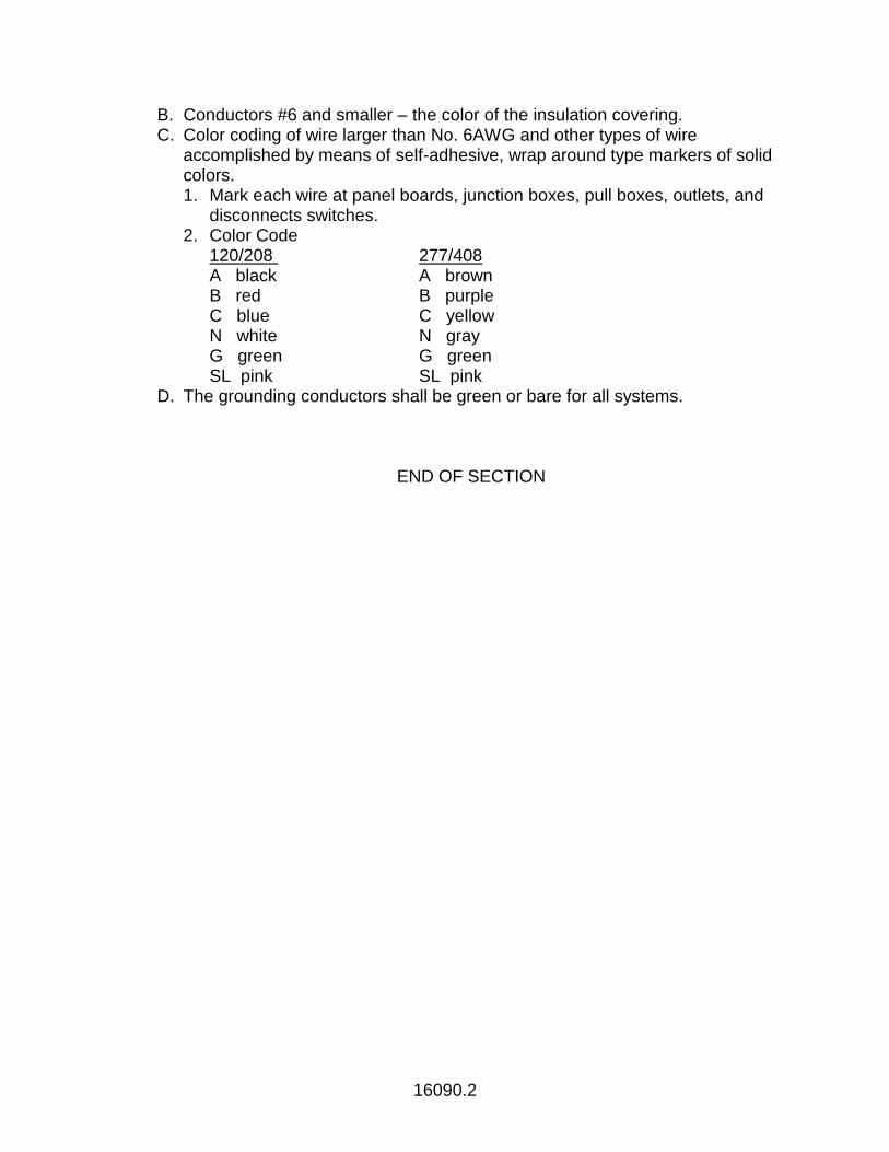
16090.2
B. Conductors #6 and smaller – the color of the insulation covering. C. Color coding of wire larger than No. 6AWG and other types of wire
accomplished by means of self-adhesive, wrap around type markers of solid colors. 1. Mark each wire at panel boards, junction boxes, pull boxes, outlets, and
disconnects switches. 2. Color Code
120/208 277/408 A black A brown B red B purple C blue C yellow N white N gray G green G green SL pink SL pink
D. The grounding conductors shall be green or bare for all systems.
END OF SECTION
16100.1
SECTION 16100
CONDUIT SYSTEMS
1.01 GENERAL
A. Install conduit systems as shown on the Drawing with installation and all components of the system: 1. UL Labeled 2. Conforming to local codes and the National Electric Code.
B. Adhere to the general routing of the conduit systems as shown on the Drawings. 1. Verify routing with existing conditions.
C. Install all conduit in the most direct, neat and workmanlike manner, employing only skilled mechanics. 1. Install conduit to conserve building space and not interfere with use of space.
D. Hold horizontal and vertical conduit as close as possible to walls, ceilings as to occupy the minimum space consistent with the proper requirements for service of adjacent elements.
E. Conduit terminations at panel board, pull boxes or outlet boxes: 1. Secured in place by locknuts inside and outside. 2. Provided with approved bushings.
F. Join rigid conduit with standard couplings according to the manufacturer’s recommendations.
1.02 CONDUIT
A. All conduit shall be new and shall bear the inspection label of the Underwriter’s Laboratories, Inc.
B. Conduit indoors – electrical metallic tubing – (EMT) 1. Cold rolled steel tubing, zinc coated inside and out. 2. Fittings – UL approved and meeting same requirements as EMT.
a. Compression type. b. Cast metal not approved.
C. Conduit underground – schedule 40 PVC with PVC fittings and solvent welded joints. 1. PVC long radius elbows shall be used in each change of direction. 2. Sealed watertight at both ends. 3. Depth of burial in accordance with NEC. 4. In a red dyed concrete envelope with 2” of encasement on all sides for
conduits 1” and larger that are not below concrete slabs. 5. Encasement not required for conduits smaller than 1”. Use direct burial
tape for conduits smaller than 1”.
16100.2
D. Flexible Metal Conduit 1. Connections to vibrating or motorized equipment shall be made with hot
dipped flexible conduit for motors or equipment located indoors. Flexible liquid type shall be compatible with the flexible conduit shall also be used for equipment being served on roof. Connections shall be compatible with the flexible conduit used Liquid-type conduit shall also be used in Class 1, Division 2, locations.
E. Conduit through slab shall be galvanized. F. Exposed exterior conduits shall be rigid steel schedule 40, mild steel pipe
zinc coated inside and out. Fittings meet same requirements as for rigid steel.
G. MC or BX flexible conduit not acceptable over 6 feet runs.
1.03 INSTALLATION
A. In suspended ceilings, support conduit runs from structure, not ceiling system construction.
B. All conduit shall be concealed unless definitely shown otherwise. C. Cap or plug conduit ends upon completion of the run until the wire is pulled. D. Swab out conduit to remove moisture and debris before wires are pulled in. E. Completely install each conduit run prior to pulling conductors. F. Route all exposed conduits parallel or perpendicular to building lines. G. After conduit routing to avoid structural obstructions, minimizing crossovers.
1.04 MINIMUM CONDUIT SIZES
A. Branch circuit (except “Home Run”): ½” B. “Home Run”: ¾” C. Switch leg: ½”
1.05 RACEWAY CONTINUITY
A. Assure the electrical continuity of all metal conduit system. 1.06 MISCELLANEOUS CONDUIT SYSTEMS
A. Provide a system of empty conduit and boxes for television, telephone and
computer data systems wiring and cabling.
1. As shown on the drawings. 2. Confirm requirements with respective systems installer.
B. Provide a complete system of empty conduit and boxes for reception of other systems as specified or shown on the drawings. 1. Confirm exact requirements and location prior to installation.
16100.3
C. Size conduit as shown on the drawings or as specified. 1. Minimum size conduit ¾”.
D. Leave a continuous, identified nylon cord in each empty conduit. E. Conduit types as specified in this section.
END OF SECTION
16103.1
SECTION 16103
GROUNDING OF ELECTRICAL SYSTEMS
1.01 GENERAL
A. Grounding of the electrical systems shall conform to the requirements of the National Electrical Code and other governing local codes.
B. Ground effectively and permanently: 1. All conduit systems. 2. All electrical equipment 3. The neutral conductor
C. Reference Standards 1. ANSI/IEEE STANDARD 142 - RECOMMENDED PRACTICE FOR
GROUNDING OF INDUSTRIAL AND COMMERCIAL POWER SYSTEMS 2. ANSI/UL 467 - SAFETY STANDARD FOR GROUNDING AND BONDING
EQUIPMENT
1.02 GROUNDING ELECTRODE
A. Provide a U.L. listed, 3/4" x 10'-0" long copper clad grounding electrode. B. Utilize U.L. listed grounding electrode connectors and approved thermal
fusion methods. C. Driven with top of electrode at grade. D. The total resistance shall not exceed 10 OHMS for service entrance grounds
and 25 OHMS for equipment grounds. 1. Provide a longer electrode, additional electrodes, or deep driven sectional
electrodes as required until the specified ground resistance is obtained. 2. The minimum distance between electrodes shall be 10'-0".
E. Measure the resistance of neutral ground using a megger earth resistance tester not less than 48 hours after the last rainfall.
1.03 GROUNDING FOR SYSTEMS 600 VOLT OR LESS
A. In the service equipment provide a ground bus separate from the neutral bar, bonded with a copper strap to the neutral bar.
B. Connect the grounding electrode conductor between the ground bus and the driven ground electrode. 1. In rigid steel conduit.
C. Install a green insulated grounding conductor as follows: 1. To all weatherproof receptacles. 2. To all isolated ground receptacles. 3. In each section of nonmetallic conduit. 4. With each panel feeder. 5. With each branch circuit with two or three pole breakers. 6. In each surface metal raceway.
END OF SECTION
Page 1 of 9
Section 16130 Aluminum Raceway and Fittings
SECTION 16130: RACEWAY AND BOXES FOR ELECTRICAL SYSTEMS
METAL RACEWAY AND FITTINGS
PART 1 – GENERAL
1.1 SUMMARY
A. SCOPE OF WORK
1. This section includes minimum requirements for product design, quality, and performance, including preparation and installation of aluminum raceway.
2. Aluminum Raceway is an enclosed pathway used for surface distribution of branch circuit electrical wiring, and cabling for voice, data, multi-media, low voltage, and optical fiber. Raceway is typically installed in existing building structures, or after construction is complete. A complete raceway system includes raceway, covers, mounting hardware, various fittings, and outlet boxes installed at specific locations. Specific codes and standards apply to electrical wires and telecommunications cables that are deployed within metal raceway. Compliance to codes and standards is required for installation, grounding and bonding, and cable deployment.
3. This section includes specific requirements for the following:
a) ALUMINUM RACEWAY: HBLALU4800 SERIES DUAL CHANNEL
4. Related Sections from Division 16: Electrical
a) 16060 Grounding and Bonding
b) 16075 Electrical Identification
c) 16120 Conductors and Cables
d) 16140 Wiring Devices
e) 16150 Wiring Connections
f) 16700 Communications
5. Related Sections from Division 27: Communications
a) 27 05 26 Grounding and Bonding for Communications Systems
b) 27 05 28.39 Surface Raceways for Communications Systems
c) 27 05 53 Identification for Communications Systems
d) 27 15 00 Communications Horizontal Cabling
Page 2 of 9
Section 16130 Aluminum Raceway and Fittings
6. Related Sections from Division 1: General Requirements
a) 01110 Summary of Work
b) 01330 Submittal Procedures
c) 01400 Quality Requirements
d) 01600 Product Requirements
e) 01630 Product Substitution Procedures
1.2 QUALITY ASSURANCE
A. Product shall be manufactured by an ISO 9001 Certified facility.
B. Product shall be of the quality and manufacture indicated.
C. Product shall be free from defects in material or workmanship.
D. Specified product is based on acceptable manufacturers listed in the Construction Documents.
E. All methods of construction that are not specified in the contract documents shall be subject to control and approval by the Owner or Owner’s Representative.
F. Product shall be lot-traceable by date code.
G. All critical manufacturing processes of the product shall have documented in-process inspections and production testing according to ISO 9001.
H. Where “approved equal” is stated, any substitute product shall be equivalent to all requirements specified, and is subject to approval.
I. Materials and work specified in this document shall comply with, and are not limited to the codes, standards and regulations listed below.
NOTE: Local codes always apply to construction. The authority having jurisdiction (AHJ) should be consulted for clarification of any regulatory details to avoid code violations.
1. National Fire Protection Association, Inc., NFPA 70: National Electric Code (NEC), 2005.
a) NEC Article 300:Wiring Methods
b) NEC Article 386: Surface Metal Raceways
c) NEC Article 250: Grounding and Bonding
d) NEC Article 800: Communications Circuits
e) NEC Article 725: Remote Control, Signaling, and Power-Limited Circuits

Page 3 of 9
Section 16130 Aluminum Raceway and Fittings
f) NEC Article 770: Optical Fiber Cables and Raceway
2. CSA C22.1-06, Canadian Electric Code (CEC), 2006
3. Underwriter’s Laboratory, Inc. (UL)
a) UL5: Standard for Surface Metal Raceways and Fittings
b) UL5C: Standard for Surface Metal Raceways and Fittings for Use with Data, Signal, and Control Circuits
c) UL50: Standard for Enclosures for Electrical Equipment
d) UL498: Attachment Plugs and Receptacles
e) UL1863: Standard for Safety – Communications Circuit Accessories
4. National Electrical Manufacturer’s Association (NEMA)
a) ANSI/NEMA WD-6-2002: Wiring Devices – Dimensional Requirements
b) NEMA 250-2003: Enclosures for Electrical Equipment
5. ANSI/TIA/EIA-568-B.1, Commercial Building Telecommunications Cabling Standard, Part 1: General Requirements, 2001.
6. ANSI/TIA/EIA-568-B.2, Commercial Building Telecommunications Cabling Standard (and all published addenda), Part 2: Balanced Twisted Pair Cabling Components, 2001.
7. ANSI/TIA/EIA-568-B.3, Optical Fiber Cabling Components Standard, 2000.
8. ANSI-J-STD-607-A, Commercial Building Grounding and Bonding Requirements for Telecommunications, 2002.
9. ANSI/TIA/EIA-569-B, Commercial Building Standard for Telecommunications Pathways and Spaces, 2003.
10. ANSI/TIA/EIA-606-A, Administration Standard for Commercial Telecommunications Infrastructure, 2002.
11. ISO/IEC 11801, Information Technology – Generic Cabling for Customer Premises, 2002.
12. ISO/IEC 18010, Information Technology – Pathways and Spaces for Customer Premises Cabling, 2005.
13. ISO/IEC 14763-1, Information Technology – Implementation and Operation of Customer Premises Cabling – Part 1: Administration, 2004.
14. BS EN 50173-1, Information Technology – Generic Cabling Systems – Part 1: General Requirements, 2002.
Page 4 of 9
Section 16130 Aluminum Raceway and Fittings
15. BS EN 50174-1, Information Technology – Cabling Installation – Part 1: Specification and Quality Assurance, 2001
16. Telecommunications Distribution Methods Manual, Current Ed., Building Industry Consulting Services International (BICSI), 2003.
17. Information Transport Systems Installation Manual, Current Ed., Building Industry Consulting Services International (BICSI), 2004.
18. Federal Communications Commission (FCC), Code of Federal Regulations, Part 68: Connection of Terminal Equipment to the Telephone Network, 1998.
19. U.S. Public Law 336.,101st Congress, ADA: Americans with Disabilities Act of 1992.
1.3 SUBMITTALS
A. Section 26 05 33 Specification Text
B. Product Data Sheet
C. Manufacturer’s Instructions
D. Product Catalog Literature
E. Product Drawing
1.4 REFERENCES
A. Master Format, 2004 Ed., The Construction Specifications Institute, 2004.
B. The Project Resource Manual, CSI Manual of Practice, 5th Ed., The Construction Specifications Institute, 2005.
1.5 WARRANTY
A. Product is warranted free of defects in material or workmanship.
B. Product is warranted to perform the intended function within design limits.
PART 2 – PRODUCTS
2.1 ALUNIMUM RACEWAY: HBLALU4800 SERIES
A. DESIGN REQUIREMENTS
1. Aluminum Raceway HBLALU4800 Series shall be a two-piece design with a base and cover, factory assembled, with mounting hardware and instructions included.
Page 5 of 9
Section 16130 Aluminum Raceway and Fittings
2. Raceway base and cover shall be an extruded aluminum construction with satin anodized finish on all surfaces.
3. Extruded raceway base and cover shall be made of 6063-T5 aluminum alloy, with a nominal wall thickness of .080”
4. Aluminum Raceway HBLALU4800 Series assembled external dimensions shall be 6.0” wide by 2.25” deep with an internal cross sectional area of 11.60 square inches.
5. Raceway base shall have an integral extruded divider separating the 6” raceway into two equally sized channels.
6. Each raceway base channel shall accept an individual cover to form two separate partitioned compartments. Partitioned compartments shall permit both power and communications wiring in separate channels.
7. Raceway base section shall be available in 10 ft lengths, and the cover sections shall be available in 5 ft lengths.
8. Raceway shall have a 40% fill total capacity of (134) Category 5e cables, or (95) Category 6 cables.
9. Assembly and disassembly of raceway base, cover, and fittings shall require no special tools.
10. Available fittings shall include couplings, internal and external elbows, tees, entrance fittings, blank end fittings, cover clips, and grounding adapters. Fittings to have anodized finish to match raceway.
11. A complete selection of full-capacity corner elbows and tee fittings shall be available with cable bend radius control features in accordance with TIA/EIA-568-B and TIA/EIA-569-B standards.
12. Assembled raceway system shall exceed requirements of ANSI/TIA/EIA-569-B standard for telecommunications pathways and spaces.
13. All fittings shall be supplied with a base where applicable.
14. Transition fittings shall be available to adapt to ½” and ¾” N.P.T. trade size conduit.
15. Device cover plates shall accept commercially available devices, including duplex devices, single 1.40” and 1.59” and 2.13” diameter receptacles, GFCI surge receptacles, and other compatible rectangular shaped devices.
16. All devices must be mounted to cover plates, which are held in place by extruded protrusions. Cover plates shall be removable by using a standard screwdriver without marking the extrusion finish.
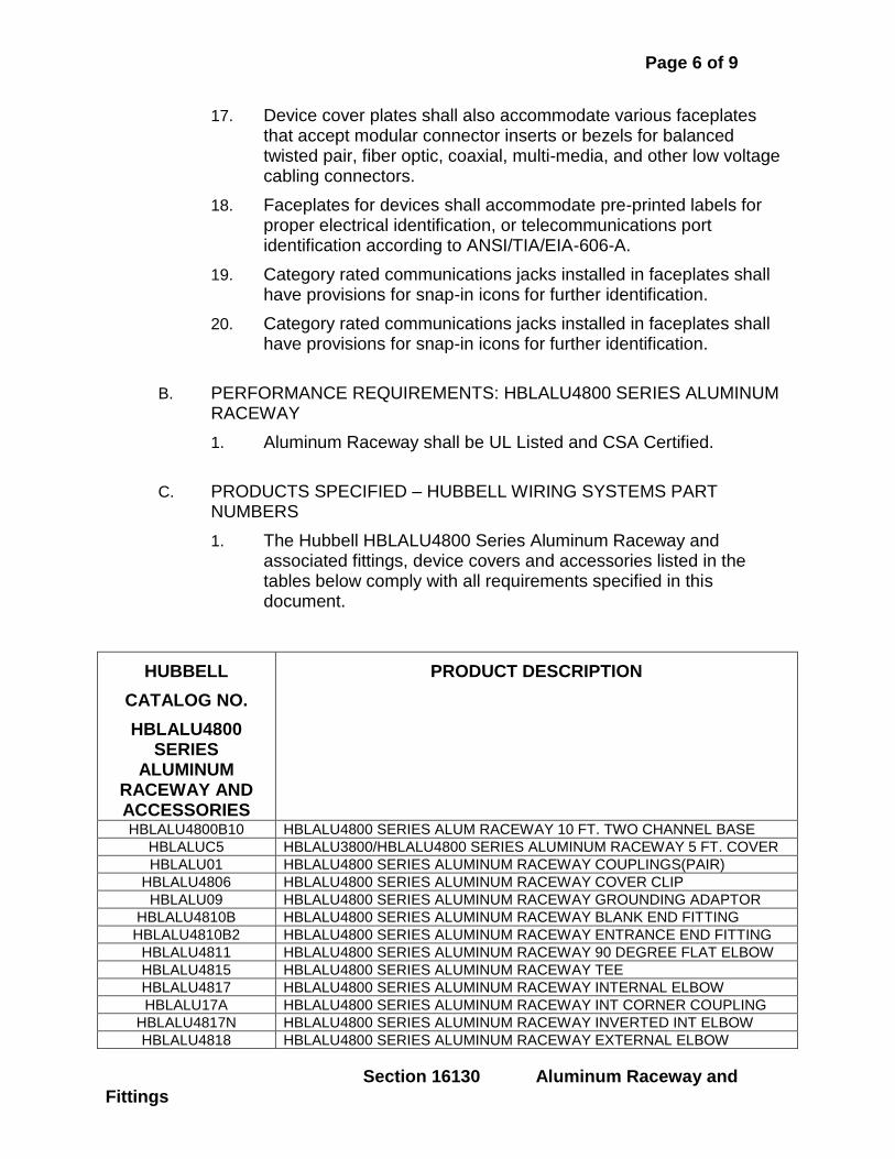
Page 6 of 9
Section 16130 Aluminum Raceway and Fittings
17. Device cover plates shall also accommodate various faceplates that accept modular connector inserts or bezels for balanced twisted pair, fiber optic, coaxial, multi-media, and other low voltage cabling connectors.
18. Faceplates for devices shall accommodate pre-printed labels for proper electrical identification, or telecommunications port identification according to ANSI/TIA/EIA-606-A.
19. Category rated communications jacks installed in faceplates shall have provisions for snap-in icons for further identification.
20. Category rated communications jacks installed in faceplates shall have provisions for snap-in icons for further identification.
B. PERFORMANCE REQUIREMENTS: HBLALU4800 SERIES ALUMINUM RACEWAY
1. Aluminum Raceway shall be UL Listed and CSA Certified.
C. PRODUCTS SPECIFIED – HUBBELL WIRING SYSTEMS PART NUMBERS
1. The Hubbell HBLALU4800 Series Aluminum Raceway and associated fittings, device covers and accessories listed in the tables below comply with all requirements specified in this document.
HUBBELL
CATALOG NO.
HBLALU4800 SERIES
ALUMINUM RACEWAY AND ACCESSORIES
PRODUCT DESCRIPTION
HBLALU4800B10 HBLALU4800 SERIES ALUM RACEWAY 10 FT. TWO CHANNEL BASE
HBLALUC5 HBLALU3800/HBLALU4800 SERIES ALUMINUM RACEWAY 5 FT. COVER
HBLALU01 HBLALU4800 SERIES ALUMINUM RACEWAY COUPLINGS(PAIR)
HBLALU4806 HBLALU4800 SERIES ALUMINUM RACEWAY COVER CLIP
HBLALU09 HBLALU4800 SERIES ALUMINUM RACEWAY GROUNDING ADAPTOR
HBLALU4810B HBLALU4800 SERIES ALUMINUM RACEWAY BLANK END FITTING
HBLALU4810B2 HBLALU4800 SERIES ALUMINUM RACEWAY ENTRANCE END FITTING
HBLALU4811 HBLALU4800 SERIES ALUMINUM RACEWAY 90 DEGREE FLAT ELBOW
HBLALU4815 HBLALU4800 SERIES ALUMINUM RACEWAY TEE
HBLALU4817 HBLALU4800 SERIES ALUMINUM RACEWAY INTERNAL ELBOW
HBLALU17A HBLALU4800 SERIES ALUMINUM RACEWAY INT CORNER COUPLING
HBLALU4817N HBLALU4800 SERIES ALUMINUM RACEWAY INVERTED INT ELBOW
HBLALU4818 HBLALU4800 SERIES ALUMINUM RACEWAY EXTERNAL ELBOW
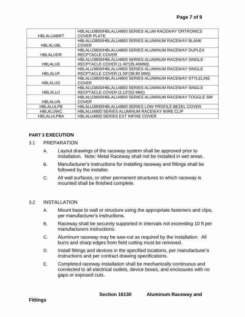
Page 7 of 9
Section 16130 Aluminum Raceway and Fittings
HBLALUABRT HBLALU3800/HBLALU4800 SERIES ALUM RACEWAY ORTRONICS COVER PLATE
HBLALUBL HBLALU3800/HBLALU4800 SERIES ALUMINUM RACEWAY BLANK COVER
HBLALUDR HBLALU3800/HBLALU4800 SERIES ALUMINUM RACEWAY DUPLEX RECPTACLE COVER
HBLALUE HBLALU3800/HBLALU4800 SERIES ALUMINUM RACEWAY SINGLE RECPTACLE COVER (1.40"(35.40MM))
HBLALUF HBLALU3800/HBLALU4800 SERIES ALUMINUM RACEWAY SINGLE RECPTACLE COVER (1.59"(38.90 MM))
HBLALUG HBLALU3800/HBLALU4800 SERIES ALUMINUM RACEWAY STYLELINE COVER
HBLALUJ HBLALU3800/HBLALU4800 SERIES ALUMINUM RACEWAY SINGLE RECPTACLE COVER (2.13"(52 MM))
HBLALUN HBLALU3800/HBLALU4800 SERIES ALUMINUM RACEWAY TOGGLE SW COVER
HBLALULPB HBLALU3800/HBLALU4800 SERIES LOW PROFILE BEZEL COVER
HBLALUWC HBLALU4800 SERIES ALUMINUM RACEWAY WIRE CLIP
HBLALULPBA HBLALU4800 SERIES EXT INFINE COVER
PART 3 EXECUTION
3.1 PREPARATION
A. Layout drawings of the raceway system shall be approved prior to installation. Note: Metal Raceway shall not be installed in wet areas.
B. Manufacturer’s instructions for installing raceway and fittings shall be followed by the installer.
C. All wall surfaces, or other permanent structures to which raceway is mounted shall be finished complete.
3.2 INSTALLATION
A. Mount base to wall or structure using the appropriate fasteners and clips, per manufacturer’s instructions.
B. Raceway shall be securely supported in intervals not exceeding 10 ft per manufacturers instructions.
C. Aluminum raceway may be saw-cut as required by the installation. All burrs and sharp edges from field cutting must be removed.
D. Install fittings and devices in the specified locations, per manufacturer’s instructions and per contract drawing specifications.
E. Completed raceway installation shall be mechanically continuous and connected to all electrical outlets, device boxes, and enclosures with no gaps or exposed cuts.
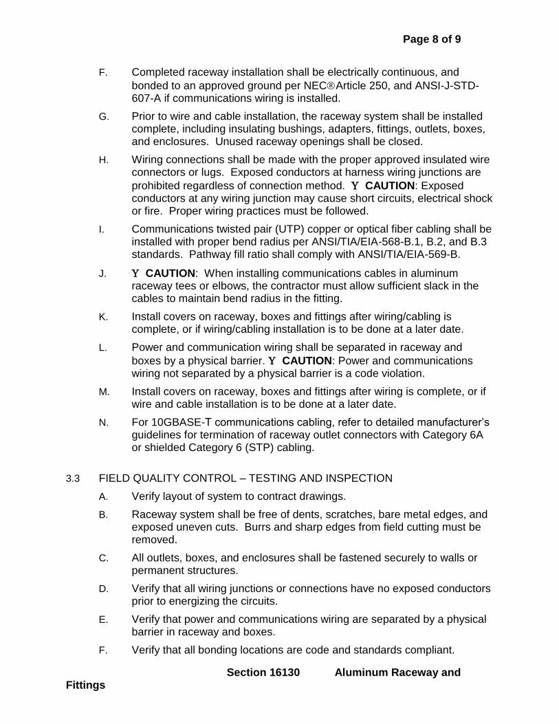
Page 8 of 9
Section 16130 Aluminum Raceway and Fittings
F. Completed raceway installation shall be electrically continuous, and
bonded to an approved ground per NECArticle 250, and ANSI-J-STD-607-A if communications wiring is installed.
G. Prior to wire and cable installation, the raceway system shall be installed complete, including insulating bushings, adapters, fittings, outlets, boxes, and enclosures. Unused raceway openings shall be closed.
H. Wiring connections shall be made with the proper approved insulated wire connectors or lugs. Exposed conductors at harness wiring junctions are
prohibited regardless of connection method. CAUTION: Exposed conductors at any wiring junction may cause short circuits, electrical shock or fire. Proper wiring practices must be followed.
I. Communications twisted pair (UTP) copper or optical fiber cabling shall be installed with proper bend radius per ANSI/TIA/EIA-568-B.1, B.2, and B.3 standards. Pathway fill ratio shall comply with ANSI/TIA/EIA-569-B.
J. CAUTION: When installing communications cables in aluminum raceway tees or elbows, the contractor must allow sufficient slack in the cables to maintain bend radius in the fitting.
K. Install covers on raceway, boxes and fittings after wiring/cabling is complete, or if wiring/cabling installation is to be done at a later date.
L. Power and communication wiring shall be separated in raceway and
boxes by a physical barrier. CAUTION: Power and communications wiring not separated by a physical barrier is a code violation.
M. Install covers on raceway, boxes and fittings after wiring is complete, or if wire and cable installation is to be done at a later date.
N. For 10GBASE-T communications cabling, refer to detailed manufacturer’s guidelines for termination of raceway outlet connectors with Category 6A or shielded Category 6 (STP) cabling.
3.3 FIELD QUALITY CONTROL – TESTING AND INSPECTION
A. Verify layout of system to contract drawings.
B. Raceway system shall be free of dents, scratches, bare metal edges, and exposed uneven cuts. Burrs and sharp edges from field cutting must be removed.
C. All outlets, boxes, and enclosures shall be fastened securely to walls or permanent structures.
D. Verify that all wiring junctions or connections have no exposed conductors prior to energizing the circuits.
E. Verify that power and communications wiring are separated by a physical barrier in raceway and boxes.
F. Verify that all bonding locations are code and standards compliant.
Page 9 of 9
Section 16130 Aluminum Raceway and Fittings
G. Verify all raceway ends are capped properly.
Page 1 of 10
Section 16130 Metal Raceway and Fittings
SECTION 16130: RACEWAY AND BOXES FOR ELECTRICAL SYSTEMS
METAL RACEWAY AND FITTINGS
PART 1 – GENERAL
1.1 SUMMARY
A. SCOPE OF WORK
1. This section includes minimum requirements for product design, quality, and performance, including preparation and installation of metal raceway.
2. Metal Raceway is an enclosed pathway used for surface distribution of branch circuit electrical wiring, and cabling for voice, data, multi-media, low voltage, and optical fiber. Raceway is typically installed in existing building structures, or after construction is complete. A complete raceway system includes raceway, covers, mounting hardware, various fittings, and outlet boxes installed at specific locations. Specific codes and standards apply to electrical wires and telecommunications cables that are deployed within metal raceway. Compliance to codes and standards is required for installation, grounding and bonding, and cable deployment.
3. This section includes specific requirements for the following:
a) METAL RACEWAY: HBL3000 SERIES SINGLE CHANNEL
4. Related Sections from Division 16: Electrical
a) 16060 Grounding and Bonding
b) 16075 Electrical Identification
c) 16120 Conductors and Cables
d) 16140 Wiring Devices
e) 16150 Wiring Connections
f) 16700 Communications
5. Related Sections from Division 27: Communications
a) 27 05 26 Grounding and Bonding for Communications Systems
b) 27 05 28.39 Surface Raceways for Communications Systems
c) 27 05 53 Identification for Communications Systems
d) 27 15 00 Communications Horizontal Cabling
Page 2 of 10
Section 16130 Metal Raceway and Fittings
6. Related Sections from Division 1: General Requirements
a) 01110 Summary of Work
b) 01330 Submittal Procedures
c) 01400 Quality Requirements
d) 01600 Product Requirements
e) 01630 Product Substitution Procedures
1.2 QUALITY ASSURANCE
A. Product shall be manufactured by an ISO 9001 Certified facility.
B. Product shall be of the quality and manufacture indicated.
C. Product shall be free from defects in material or workmanship.
D. Specified product is based on acceptable manufacturers listed in the Construction Documents.
E. All methods of construction that are not specified in the contract documents shall be subject to control and approval by the Owner or Owner’s Representative.
F. Product shall be lot-traceable by date code.
G. All critical manufacturing processes of the product shall have documented in-process inspections and production testing according to ISO 9001.
H. Where “approved equal” is stated, any substitute product shall be equivalent to all requirements specified, and is subject to approval.
I. Materials and work specified in this document shall comply with, and are not limited to the codes, standards and regulations listed below.
NOTE: Local codes always apply to construction. The authority having jurisdiction (AHJ) should be consulted for clarification of any regulatory details to avoid code violations.
1. National Fire Protection Association, Inc., NFPA 70: National Electric Code (NEC), 2005.
a) NEC Article 300:Wiring Methods
b) NEC Article 386: Surface Metal Raceways
c) NEC Article 250: Grounding and Bonding
d) NEC Article 800: Communications Circuits
e) NEC Article 725: Remote Control, Signaling, and Power-Limited Circuits
Page 3 of 10
Section 16130 Metal Raceway and Fittings
f) NEC Article 770: Optical Fiber Cables and Raceway
2. CSA C22.1-06, Canadian Electric Code (CEC), 2006
3. Underwriter’s Laboratory, Inc. (UL)
a) UL5: Standard for Surface Metal Raceways and Fittings
b) UL5C: Standard for Surface Metal Raceways and Fittings for Use with Data, Signal, and Control Circuits
c) UL50: Standard for Enclosures for Electrical Equipment
d) UL498: Attachment Plugs and Receptacles
e) UL1863: Standard for Safety – Communications Circuit Accessories
4. National Electrical Manufacturer’s Association (NEMA)
a) ANSI/NEMA WD-6-2002: Wiring Devices – Dimensional Requirements
b) NEMA 250-2003: Enclosures for Electrical Equipment
5. ANSI/TIA/EIA-568-B.1, Commercial Building Telecommunications Cabling Standard, Part 1: General Requirements, 2001.
6. ANSI/TIA/EIA-568-B.2, Commercial Building Telecommunications Cabling Standard (and all published addenda), Part 2: Balanced Twisted Pair Cabling Components, 2001.
7. ANSI/TIA/EIA-568-B.3, Optical Fiber Cabling Components Standard, 2000.
8. ANSI-J-STD-607-A, Commercial Building Grounding and Bonding Requirements for Telecommunications, 2002.
9. ANSI/TIA/EIA-569-B, Commercial Building Standard for Telecommunications Pathways and Spaces, 2003.
10. ANSI/TIA/EIA-606-A, Administration Standard for Commercial Telecommunications Infrastructure, 2002.
11. ISO/IEC 11801, Information Technology – Generic Cabling for Customer Premises, 2002.
12. ISO/IEC 18010, Information Technology – Pathways and Spaces for Customer Premises Cabling, 2005.
13. ISO/IEC 14763-1, Information Technology – Implementation and Operation of Customer Premises Cabling – Part 1: Administration, 2004.
14. BS EN 50173-1, Information Technology – Generic Cabling Systems – Part 1: General Requirements, 2002.
Page 4 of 10
Section 16130 Metal Raceway and Fittings
15. BS EN 50174-1, Information Technology – Cabling Installation – Part 1: Specification and Quality Assurance, 2001
16. Telecommunications Distribution Methods Manual, Current Ed., Building Industry Consulting Services International (BICSI), 2003.
17. Information Transport Systems Installation Manual, Current Ed., Building Industry Consulting Services International (BICSI), 2004.
18. Federal Communications Commission (FCC), Code of Federal Regulations, Part 68: Connection of Terminal Equipment to the Telephone Network, 1998.
19. U.S. Public Law 336.,101st Congress, ADA: Americans with Disabilities Act of 1992.
1.3 SUBMITTALS
A. Section 26 05 33 Specification Text
B. Product Data Sheet
C. Manufacturer’s Instructions
D. Product Catalog Literature
E. Product Drawing
1.4 REFERENCES
A. Master Format, 2004 Ed., The Construction Specifications Institute, 2004.
B. The Project Resource Manual, CSI Manual of Practice, 5th Ed., The Construction Specifications Institute, 2005.
1.5 WARRANTY
A. Product is warranted free of defects in material or workmanship.
B. Product is warranted to perform the intended function within design limits.
PART 2 – PRODUCTS
2.1 METAL RACEWAY: HBL3000 SERIES
A. DESIGN REQUIREMENTS
1. Metal Raceway HBL3000 Series shall be a two-piece design with a base and cover, with mounting hardware and instructions included.
Page 5 of 10
Section 16130 Metal Raceway and Fittings
2. Metal raceway base, cover, and related fittings shall be a formed steel construction.
3. Metal Raceway HBL3000 Series base and cover shall have a minimum material thickness of 0.040”.
4. Metal raceway base, cover, and related fittings shall have an Ivory or Gray color powder coat paint finish on all external surfaces. Custom colors shall be available on a make-to-order basis. Field re-painting shall be permissible as required.
5. Metal Raceway HBL3000 Series assembled external dimensions shall be 2.75” wide by 1.53” deep with an internal cross sectional area of 3.70 square inches.
6. Raceway base section shall be available in 10 ft lengths, and the cover section shall be available in 5 ft lengths.
7. A compact, color-matched touch-up paint pen shall be available, in gray or ivory, to facilitate coating of nicks, scratches, or exposed metal edges that may be incurred during construction.
8. Raceway shall have a 40% fill capacity of (43) Category 5e cables, or (30) Category 6 cables.
9. Raceway shall have a 40% fill capacity of (15) Category 6A cables, or (22) shielded Category 6 cables.
10. Raceway shall have a tool available for field cutting of the cover and base.
11. Assembly and disassembly of raceway base, cover, and fittings shall require no special tools.
12. Available fittings shall include couplings, internal and external elbows, tees, entrance fittings, blank end fittings, cover clips, and bushings. Fitting covers shall be painted with powder coat finish to match the raceway.
13. A complete selection of full-capacity corner elbows and tee fittings shall be available with 1 ½” cable bend radius control features in accordance with TIA/EIA-568-B and TIA/EIA-569-B standards.
14. All fittings shall be supplied with a base where applicable
15. Installed fittings shall be designed to overlap the raceway to cover exposed or uneven edges from field cutting.
16. A UL classified transition fitting shall be available to adapt to
installed Wiremold raceway of similar style as required.
17. Reducer fittings shall be available to transition from HBL3000 series raceway to HBL2000 series raceway.
Page 6 of 10
Section 16130 Metal Raceway and Fittings
18. Device boxes shall have a removable knockout portion to permit metal raceway entry and exit. Device boxes shall serve as an extension box by removing a single rectangular knockout.
19. Device boxes shall be available in standard NEMA single- and double-gang versions. Two-gang device boxes shall accommodate extra deep devices. Device box shall have a total height of 2.75”. Devices shall have the ability to be mounted flush or in conjunction with standard faceplates.
20. Device boxes shall have a single seam construction with rounded corners to eliminate sharp edges.
21. Assembled device box front face design shall permit flush mounting of standard wall plates to minimize perimeter profile exposure.
22. Device boxes shall have threaded standoff posts attached to the base, to facilitate mounting of covers with short screws for ease of alignment during installation.
23. A 6.38” square by 1.88” deep utility box shall be available, and may be used as a tee, cross, junction box, or housing for branch circuit extensions.
24. Device boxes and covers shall be painted with an enamel finish to match raceway color.
25. Device boxes shall accommodate various faceplates that accept modular connector inserts or bezels for balanced twisted pair, fiber optic, coaxial, multi-media, and other low voltage cabling connectors.
26. Faceplates for device boxes shall accommodate pre-printed labels for proper electrical identification, or telecommunications port identification according to ANSI/TIA/EIA-606-A.
27. Faceplates for device boxes shall be available in colors that match the device box and raceway.
B. PERFORMANCE REQUIREMENTS: HBL3000 SERIES METAL RACEWAY
1. Metal Raceway shall be UL Listed and CSA Certified.
C. PRODUCTS SPECIFIED – HUBBELL WIRING SYSTEMS PART NUMBERS
1. The Hubbell HBL3000 Series Metal Raceway and associated fittings, tools, device boxes, and accessories listed in the tables below comply with all requirements specified in this document.
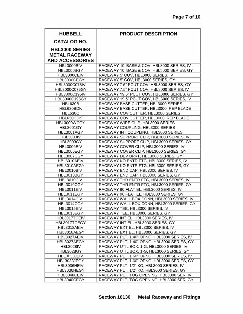
Page 7 of 10
Section 16130 Metal Raceway and Fittings
HUBBELL
CATALOG NO.
HBL3000 SERIES METAL RACEWAY
AND ACCESSORIES
PRODUCT DESCRIPTION
HBL3000BIV RACEWAY 10’ BASE & COV, HBL3000 SERIES, IV
HBL3000BGY RACEWAY 10’ BASE & COV, HBL3000 SERIES, GY
HBL3000CEIV RACEWAY 5’ COV, HBL3000 SERIES, IV
HBL3000CEGY RACEWAY 5’ COV, HBL3000 SERIES, GY
HBL3000C075IV RACEWAY 7.5” PCUT COV, HBL3000 SERIES, GY
HBL3000C075GY RACEWAY 7.5” PCUT COV, HBL3000 SERIES, IV
HBL3000C195IV RACEWAY 19.5” PCUT COV, HBL3000 SERIES, GY
HBL3000C195GY RACEWAY 19.5” PCUT COV, HBL3000 SERIES, IV
HBL630B RACEWAY BASE CUTTER, HBL3000 SERIES
HBL630BDK RACEWAY BASE CUTTER, HBL3000, REP BLADE
HBL630C RACEWAY COV CUTTER, HBL3000 SERIES
HBL630CDK RACEWAY COV CUTTER, HBL3000, REP BLADE
HBL3000WCGY RACEWAY WIRE CLIP, HBL3000 SERIES
HBL3001GY RACEWAY COUPLING, HBL3000 SERIES
HBL3001AGY RACEWAY INT COUPLING, HBL3000 SERIES
HBL3003IV RACEWAY SUPPORT CLIP, HBL3000 SERIES, IV
HBL3003GY RACEWAY SUPPORT CLIP, HBL3000 SERIES, GY
HBL3006EIV RACEWAY COVER CLIP, HBL3000 SERIES, IV
HBL3006EGY RACEWAY COVER CLIP, HBL3000 SERIES, GY
HBL3007CGY RACEWAY DEV BRKT, HBL3000 SERIES, GY
HBL3010AEIV RACEWAY KO ENTR FTG, HBL3000 SERIES, IV
HBL3010AEGY RACEWAY KO ENTR FTG, HBL3000 SERIES, GY
HBL3010BIV RACEWAY END CAP, HBL3000 SERIES, IV
HBL3010BGY RACEWAY END CAP, HBL3000 SERIES, GY
HBL3010CIV RACEWAY THR ENTR FTG, HBL3000 SERIES, IV
HBL3010CGY RACEWAY THR ENTR FTG, HBL3000 SERIES, GY
HBL3011EIV RACEWAY 90 FLAT EL, HBL3000 SERIES, IV
HBL3011EGY RACEWAY 90 FLAT EL, HBL3000 SERIES, GY
HBL3014CIV RACEWAY WALL BOX CONN, HBL3000 SERIES, IV
HBL3014CGY RACEWAY WALL BOX CONN, HBL3000 SERIES, GY
HBL3015EIV RACEWAY TEE, HBL3000 SERIES, IV
HBL3015EGY RACEWAY TEE, HBL3000 SERIES, GY
HBL3017TCEIV RACEWAY INT EL, HBL3000 SERIES, IV
HBL3017TCEGY RACEWAY INT EL, HBL3000 SERIES, GY
HBL3018AEIV RACEWAY EXT EL, HBL3000 SERIES, IV
HBL3018AEGY RACEWAY EXT EL, HBL3000 SERIES, GY
HBL3027AEIV RACEWAY PLT, 1.40" OPNG, HBL3000 SERIES, IV
HBL3027AEGY RACEWAY PLT, 1.40" OPNG, HBL3000 SERIES, GY
HBL3028IV RACEWAY UTIL BOX, 1-G, HBL3000 SERIES, IV
HBL3028GY RACEWAY UTIL BOX, 1-G, HBL3000 SERIES, GY
HBL3033JEIV RACEWAY PLT, 1.60" OPNG, HBL3000 SERIES, IV
HBL3033JEGY RACEWAY PLT, 1.60" OPNG, HBL3000 SERIES, GY
HBL3036HEIV RACEWAY PLT, 1/2" KO, HBL3000 SERIES, IV
HBL3036HEGY RACEWAY PLT, 1/2" KO, HBL3000 SERIES, GY
HBL3040CEIV RACEWAY PLT, TOG OPENING, HBL3000 SER, IV
HBL3040CEGY RACEWAY PLT, TOG OPENING, HBL3000 SER, GY
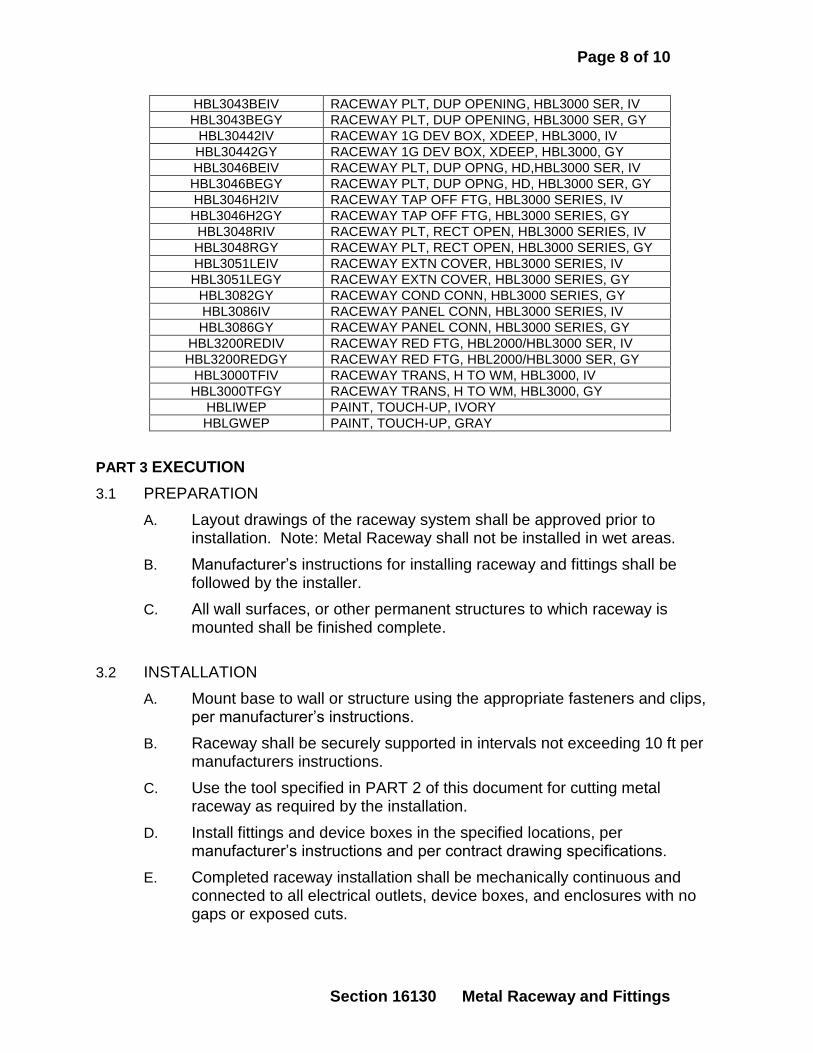
Page 8 of 10
Section 16130 Metal Raceway and Fittings
HBL3043BEIV RACEWAY PLT, DUP OPENING, HBL3000 SER, IV
HBL3043BEGY RACEWAY PLT, DUP OPENING, HBL3000 SER, GY
HBL30442IV RACEWAY 1G DEV BOX, XDEEP, HBL3000, IV
HBL30442GY RACEWAY 1G DEV BOX, XDEEP, HBL3000, GY
HBL3046BEIV RACEWAY PLT, DUP OPNG, HD,HBL3000 SER, IV
HBL3046BEGY RACEWAY PLT, DUP OPNG, HD, HBL3000 SER, GY
HBL3046H2IV RACEWAY TAP OFF FTG, HBL3000 SERIES, IV
HBL3046H2GY RACEWAY TAP OFF FTG, HBL3000 SERIES, GY
HBL3048RIV RACEWAY PLT, RECT OPEN, HBL3000 SERIES, IV
HBL3048RGY RACEWAY PLT, RECT OPEN, HBL3000 SERIES, GY
HBL3051LEIV RACEWAY EXTN COVER, HBL3000 SERIES, IV
HBL3051LEGY RACEWAY EXTN COVER, HBL3000 SERIES, GY
HBL3082GY RACEWAY COND CONN, HBL3000 SERIES, GY
HBL3086IV RACEWAY PANEL CONN, HBL3000 SERIES, IV
HBL3086GY RACEWAY PANEL CONN, HBL3000 SERIES, GY
HBL3200REDIV RACEWAY RED FTG, HBL2000/HBL3000 SER, IV
HBL3200REDGY RACEWAY RED FTG, HBL2000/HBL3000 SER, GY
HBL3000TFIV RACEWAY TRANS, H TO WM, HBL3000, IV
HBL3000TFGY RACEWAY TRANS, H TO WM, HBL3000, GY
HBLIWEP PAINT, TOUCH-UP, IVORY
HBLGWEP PAINT, TOUCH-UP, GRAY
PART 3 EXECUTION
3.1 PREPARATION
A. Layout drawings of the raceway system shall be approved prior to installation. Note: Metal Raceway shall not be installed in wet areas.
B. Manufacturer’s instructions for installing raceway and fittings shall be followed by the installer.
C. All wall surfaces, or other permanent structures to which raceway is mounted shall be finished complete.
3.2 INSTALLATION
A. Mount base to wall or structure using the appropriate fasteners and clips, per manufacturer’s instructions.
B. Raceway shall be securely supported in intervals not exceeding 10 ft per manufacturers instructions.
C. Use the tool specified in PART 2 of this document for cutting metal raceway as required by the installation.
D. Install fittings and device boxes in the specified locations, per manufacturer’s instructions and per contract drawing specifications.
E. Completed raceway installation shall be mechanically continuous and connected to all electrical outlets, device boxes, and enclosures with no gaps or exposed cuts.
Page 9 of 10
Section 16130 Metal Raceway and Fittings
F. Completed raceway installation shall be electrically continuous, and
bonded to an approved ground per NEC Article 250, and ANSI-J-STD-607-A if communications wiring is installed.
G. Prior to wire and cable installation, the raceway system shall be installed complete, including insulating bushings, adapters, fittings, outlets, boxes, and enclosures. Unused raceway openings shall be closed.
H. Wiring connections shall be made with the proper approved insulated wire connectors or lugs. Exposed conductors at harness wiring junctions are
prohibited regardless of connection method. CAUTION: Exposed conductors at any wiring junction may cause short circuits, electrical shock or fire. Proper wiring practices must be followed.
I. Communications twisted pair (UTP) copper or optical fiber cabling shall be installed with proper bend radius per ANSI/TIA/EIA-568-B.1, B.2, and B.3 standards. Pathway fill ratio shall comply with ANSI/TIA/EIA-569-B.
J. Communications twisted pair copper cabling shall not share the same pathway as electrical wiring without a physical partition between the media.
K. Install covers on raceway, boxes and fittings after wiring/cabling is complete, or if wiring/cabling installation is to be done at a later date.
L. Power and communication wiring shall be separated in raceway and
boxes by a physical barrier. CAUTION: Power and communications wiring not separated by a physical barrier is a code violation.
M. Install covers on raceway, boxes and fittings after wiring is complete, or if wire and cable installation is to be done at a later date.
N. For 10GBASE-T communications cabling, refer to detailed manufacturer’s guidelines for termination of raceway outlet connectors with Category 6A or shielded Category 6 (STP) cabling.
3.3 FIELD QUALITY CONTROL – TESTING AND INSPECTION
A. Verify layout of system to contract drawings.
B. Raceway system shall be free of dents, scratches, bare metal edges, and exposed uneven cuts.
C. All outlets, boxes, and enclosures shall be fastened securely to walls or permanent structures.
D. Verify that all wiring junctions or connections have no exposed conductors prior to energizing the circuits.
E. Verify that all bonding locations are code and standards compliant.
F. Verify all raceway ends are capped properly.
Page 10 of 10
Section 16130 Metal Raceway and Fittings
G. Verify that power and communications wiring are separated by a physical barrier in raceway and boxes.
16131.1
SECTION 16131
PULL BOXES AND JUNCTION BOXES 1.01 GENERAL
A. DESCRIPTION: 1. Provide and install outlet boxes as shown on drawings, as specified, or as
required to make systems complete. 2. Provide and install at every outlet, a standard hot galvanized or
sheradized steel outlet box of approved design and construction, and of such form and dimensions as best adapted to the specific location, king of fixture, or device to be used and the number, size and arrangement of conduits connected thereto.
1.02 PRODUCTS
A. On exposed work, 10'-4" above floor, down to floor level, cast metal outlets, junction boxes or fittings shall be used.
B. Provide covers with all outlet boxes requiring covers. The covers shall be of such construction and design as to fit exactly and match the outlet box on which they are installed. Switch boxes, junction boxes and all other boxes to which not fixture or device is to be attached, shall be fitted with blank covers. All outlet box covers of all types shall match in design and color.
1.03 EXECUTION
A. Unless otherwise specified or directed, outlet boxes shall be set with edges flush with the finished surface, level and square. Carefully check and correct position prior to final finishing. All boxes shall be clean and kept clean throughout the job progress.
B. Outlet boxes shall be firmly anchored in place and shall be provided with approved fixture studs where required. Fixture studs shall be applied to boxes from rear and securely bolted to box. Only such holes to be used for entering conduits shall be open.
C. Where outlet boxes and conduit are supports for light fixtures, outlet boxes shall be supported by span from T-bar, channel to channel or from metal lath channels.
D. Pull and junction boxes shall be provided where indicated or where necessary to facilitate installation of the systems of wiring. Secure approval of the Architect for all boxes and locations not shown that Contractor may wish to install. These boxes shall be code size and gauge or as shown and shall be constructed of galvanized sheet steel suitable for wall mounting. Covers for flush mounted junction or pull boxes larger than 4-gang shall be finished as electrical cabinet fronts, but shall be one-piece and secured with screws.
16131.2
Covers or fronts for flush junction or pull boxes shall be 1 2" larger than the box. Covers for surface junction or pull boxes shall be the same size and of the same material as the box.
E. The following are the ADA Accessibility Guidelines for switches and outlets as required by the ADA: 1. ADA Accessibility Guidelines:
ADA 4.2.5 forward reach - max. 48" Figure 5A - min. 15" When counter is less than 20" - max. 48" When counter is less than 20"-25" - max. 44" 4.2.6 side reach - max. 54" Figure 6 - max. 9" When counter is 24" deep - max. 46"
2. Heights of switches and outlets as required by ADA: Wall switches - 4-0" Wall switches above countertops - 3'-8" Wall receptacles - 1'-6" Wall receptacles above countertops - 3'-9" Disconnect Switches - 5'-6" Disconnect Switches (handicapped height) - 4'-6"
3. Other special outlets shall be installed as shown or specified or as directed by the Architect.
F. Small junction boxes for control or branch wiring shall be as specified for outlet boxes.
G. Floor outlets shall not be installed until location is verified with the Architect. H. The drawings indicate the approximate locations of outlets and their grouping
on the various circuits with home runs to the respective distribution panels. The exact location shall be carefully planned on job site in conference with the Architect or the Architect's representative. In case of doubt as to the proper mounting of any outlet, the Architect shall be consulted. Verify with Architect the location of any outlet not noted, prior to installation.
I. On Architect's request, the Contractor shall make minor changes of outlet locations, before rough-in, up to a distance of 10' from shown location. There shall be no additional charge to the Owner.
END OF SECTION
16132.1
SECTION 16132
FLOOR BOXES
PART 1 GENERAL
1.1 SCOPE
The floor box provides the interface between power and communication cabling in an on grade or above grade concrete floor where power and/or communication services are required.
1.2 CLASSIFICATION AND USE This floor box shall have been examined and tested by Underwriters Laboratories Inc. to Standard UL514A and/or UL514C and Canadian Standard C22.2, No. 18-92 and bear the U.S. and Canadian UL Listing Mark. This floor box shall also conform to the standards set in the National Electrical Code, Section 300-21. This floor box shall also have been evaluated by UL to meet the applicable U.S. and Canadian safety standards for scrub water exclusion when used on tile, terrazzo, wood, and carpet covered floors.
PART 2 PRODUCT
2.1 MANUFACTURER
The Walker floor box described shall be manufactured by The Wiremold Company. Floor boxes of other manufacturers may be considered, if equal in functionality and quality, by written approval of the specifying engineer and shall meet all the performance standards specified herein. In addition, the contractor shall have ten days to submit to the specifying engineer a working sample from any other manufacturer.
2.2 MATERIALS
2.2.1 Floor Boxes
2.2.1.1 RFB2 Series Floor Box The floor box shall be manufactured from stamped steel and be approved for use on above grade floors. The box shall be 13 1/8" L x 6 ½" W x 3 7/16" H [333mm x 165mm x 87mm]. There shall be two independent wiring compartments that allow capacity for up to two duplex receptacles and/or communication services. The RFB2 Series Box shall permit tunneling from end power compartment to end power compartment. Each of the two compartments shall have a minimum wiring capacity of 50 cu in. [822 ml3]. The box shall provide the following number of conduit knockouts: two 1/2" [12.7mm], six 3/4" [19.1mm], two 1" [25mm] and four 1 1/4" [32mm]. The box shall be fully adjustable, providing a maximum of 1 3/8" [35mm] pre-pour adjustment, and a maximum of 3/4" [19.1mm] after-pour adjustment. The box shall provide a series of device mounting plates that will accept both duplex power devices, as well as plates that will accommodate Ortronics workstation connectivity outlets and modular inserts, the Pass & Seymour Network Wiring System, and other open system devices.
2.2.1.2 RFB2-SS Series Floor Box The floor box shall be manufactured from stamped steel and be approved for use on above grade floors. The box shall be 13 1/8" L x 6 1/2" W x 2 5/8" H [333mm x 165mm x 67mm]. There shall be two independent wiring compartments that allow capacity for up to two duplex receptacles and/or communication services. The RFB2-SS Series Box shall permit tunneling
16132.2
from end power compartment to end power compartment. Each of the two compartments shall have a minimum wiring capacity of 38 cu in. [622 ml3]. The box shall provide the following number of conduit knockouts: Two 1/2" [12.7 mm] and twelve 3/4" [19.1 mm]. The box shall be fully adjustable, providing a maximum of 1 3/8" [35mm] pre-pour adjustment, and a maximum of 3/4" [19.1mm] after-pour adjustment. The box shall provide a series of device mounting plates that will accept both duplex power devices, as well as plates that will accommodate Ortronics workstation connectivity outlets and modular inserts, the Pass & Seymour Network Wiring System, and other open system devices.
2.2.1.3 RFB2-OG Series Floor Box The floor box shall be manufactured from stamped steel and be painted with a fusion-bonded epoxy designed for use on metal reinforcement bar and related accessories before encapsulation in concrete, and be approved for use on grade and above grade floors. The box shall be 13 1/8" L x 6 1/2" W x 3 7/16" H [333mm x 165mm x 87mm]. There shall be two independent wiring compartments that allow capacity for up to two duplex receptacles and/or communication services. The RFB2 Series Box shall permit tunneling from end power compartment to end power compartment. Each of the two compartments shall have a minimum wiring capacity of 50 cu in. [822 ml3]. The box shall provide the following number of conduit knockouts: two 1/2" [12.7mm], six 3/4" [19.1mm], two 1" [25mm] and four 1 1/4" [32mm]. The box shall be fully adjustable, providing a maximum of 1 3/8" [35mm] pre-pour adjustment, and a maximum of 3/4" [19.1mm] after-pour adjustment. The box shall provide a series of device mounting plates that will accept both duplex power devices, as well as plates that will accommodate Ortronics workstation connectivity outlets and modular inserts, the Pass & Seymour Network Wiring System, and other open system devices.
2.2.1.4 RFB4 and RFB4-4DB Series Floor Boxes The floor box shall be manufactured from stamped steel and be approved for use on above grade floors. The box shall be 12 3/4" L x 10" W x 3 7/16" H [324mm x 254mm x 87mm]. There shall be four independent wiring compartments that allow capacity for up to four duplex receptacles and/or communication services. The RFB4 Series Box shall permit tunneling from end power compartment to end power compartment. The RFB4-4DB Series Box shall permit tunneling from adjacent or opposite compartments. Two of the four compartments shall have a minimum wiring capacity of 16.4 cu in. [269cu cm], one compartment shall have a minimum capacity of 32.3 cu in. [529cu cm], and one compartment shall have a minimum capacity of 50 cu in. [820cu cm]. The box shall provide the following number of conduit knockouts: one 1/2" [12.7mm], three 1" [25mm], six 3/4" [19.1mm], and six 1 1/4" [32mm]. The box shall be fully adjustable, providing a maximum of 1 7/8" [47.7mm] pre-pour adjustment, and a maximum of 3/4" [19.1mm] after-pour adjustment. The box shall provide a series of device mounting plates that will accept both duplex power devices, as well as plates that will accommodate Ortronics® workstation connectivity outlets and modular inserts, the Pass & Seymour Network Wiring System, and other open system devices.
2.2.1.5 RFB4-CI-1 Series Floor Box This box shall be manufactured from cast-iron and be approved for use on grade and above grade floors. The box shall be 14 1/2" L x 11 7/8" W x 3 7/16" H [368mm x 302mm x 87mm]. There shall be four independent wiring compartments that allow capacity for up to four duplex receptacles and/or communication services. The RFB4-CI-1 Series Box shall permit tunneling from adjacent or opposite compartments. Two of the four compartments shall have a minimum wiring capacity of 27 cu in. [443cu cm], and two compartments shall have a minimum wiring capacity of 36 cu in. [590cu cm]. The box shall provide the following number of conduit hubs: four 1" [25mm] and four 1 1/4" [32mm]. The box shall be fully adjustable, providing a maximum of 1 7/8" [48mm] pre-pour adjustment, and a maximum of 3/4" [19.1mm] after-pour adjustment.
2.2.1.6 RFB4-SS Series Floor Box
16132.3
This box shall be manufactured from stamped-steel and be approved for use on above grade floors. The box shall be 13 5/8" L x 10" W x 2 7/16" H [346mm x 254mm x 62mm]. There shall be four independent wiring compartments that allow capacity for up to four duplex receptacles and/or communication services. The RFB4-SS Series Box shall permit feed through tunneling from adjacent compartments. Two of the four compartments shall have a minimum wiring capacity of 15.7 cu in. [257cu cm], and two compartments shall have a minimum wiring capacity of 31.2 cu in. [511cu cm]. The box shall provide the following number of conduit knockouts: two 1/2" [12.7mm], six 3/4" [19.1mm], and eight 1" [25mm]. The box shall be fully adjustable, providing a maximum of 1 7/8" [48mm] pre-pour adjustment, and a maximum of 3/4" [19.1mm] after-pour adjustment.
2.2.1.7 RFB6 Series Floor Box The floor box shall be manufactured from stamped steel and be approved for use on above grade floors. The box shall be 13 1/8" L x 12 1/2" W x 3 1/4" H [333mm x 317mm x 83mm]. There shall be six independent wiring compartments that allow capacity for up to six duplex receptacles and/or communication services. The RFB6 Series Box shall permit feed through tunneling from adjacent compartments. Two of the six compartments shall have a minimum wiring capacity of 23 cu in. [376cu cm], and four compartments shall have a minimum wiring capacity of 52cu in. [850cu cm]. The box shall provide the following number of conduit knockouts: twelve 3/4" [19.1mm], four 1" [25mm], twelve 1 1/4" [32mm]. The box shall be fully adjustable, providing a maximum of 1 3/8" [35mm] pre-pour adjustment, and a maximum of 3/4" [19.1mm] after-pour adjustment. The box shall provide a series of device mounting plates that will accept both duplex power devices, as well as plates that will accommodate Ortronics workstation connectivity outlets and modular inserts, the Pass & Seymour Network Wiring System, and other open system devices.
2.2.1.8 RFB6-OG Series Floor Box The floor box shall be manufactured from stamped steel and be painted with a fusion-bonded epoxy designed for use on metal reinforcement bar and related accessories before encapsulation in concrete, and be approved for use on grade and above grade floors. The box shall be 13 1/8" L x 12 1/2" W x 3 1/4" H [333mm x 317mm x 83mm]. There shall be six independent wiring compartments that allow capacity for up to six duplex receptacles and/or communication services. The RFB6 Series Box shall permit feed through tunneling from adjacent compartments. Two of the six compartments shall have a minimum wiring capacity of 23 cu in. [376cu cm], and four compartments shall have a minimum wiring capacity of 52cu in. [850cu cm]. The box shall provide the following number of conduit knockouts: twelve 3/4" [19.1mm], four 1" [25mm], twelve 1 1/4" [32mm]. The box shall be fully adjustable, providing a maximum of 1 3/8" [35mm] pre-pour adjustment, and a maximum of 3/4" [19.1mm] after-pour adjustment. The box shall provide a series of device mounting plates that will accept both duplex power devices, as well as plates that will accommodate Ortronics workstation connectivity outlets and modular inserts, the Pass & Seymour Network Wiring System, and other open system devices.
2.2.2 Activation Covers Activation covers shall be manufactured of die-cast aluminum or die-cast zinc, and be available in a brushed aluminum finish, plated brass finish, or a powder-coated paint finish. Activation covers shall be available in flanged and flangeless versions. Covers shall be available with options for tile or carpet inserts, flush covers, or covers with one 1" trade size screw plug opening and one combination 1 1/4" and 2" trade size screw plug openings for furniture feed applications. Flanged covers shall be 7 3/4" L x 6 9/16" W [197mm x 167mm]. Flangeless covers shall be 6 3/4" L x 5 9/16" W [171mm x 142mm].
16132.4
The activation cover shall have been evaluated by UL to meet the applicable U.S. and Canadian safety standards for scrub water exclusion when used on tile, terrazzo, wood, and carpet covered floors.
2.2.3 Communication Modules Mounting Accessories The floor box manufacturer shall provide a complete line of faceplates and bezels to facilitate mounting of UTP, STP (150 ohm), fiber optic, coaxial, and communication devices. The box shall provide a series of device mounting plates that will accommodate Ortronics workstation connectivity outlets and modular inserts, the Pass and Seymour Network Wiring System, and other open system devices.
SECTION 16140-1 WIRING DEVICES
PART 1 GENERAL
A. DESCRIPTION:
1. Provide and install all devices indicated on the drawings, as specified, and as required to form complete and integrated systems.
2. Flush switches shall be as specified. Terminal screws or connectors shall be designed to accommodate and firmly terminate up to No. 10 solid conductors.
3. Switches controlling inductive (fluorescent) lighting or heating loads in excess of 800 watts up to 1600 watts shall be rated at not less than 20 amperes.
4. Switches controlling or disconnecting motor loads in excess of 1/3 HP shall be HP rated and approved for motor control or disconnect service.
5. Devices shall be as manufactured by G.E., Arrow Hart, Hubbell, P&S, Bryant or approved equal.
6. Devices shall be ivory plastic. On walls dark in color, verify color with Architect.
1.01 SUMMARY
A. Section includes the following types of wiring devices:
1. Receptacles
2. Switches
3. Ground Fault Circuit Interrupters
4. Isolated Ground Receptacles
5. TVSS Receptacles
6. Locking Receptacles
7. Wall Plates
1.02 REFERENCES
A. Wiring devices and components shall be designed, manufactured, tested and installed
to comply with NFPA 70, NEC, UL standards 498 (receptacles), 20 (switches), 508
(motor starter switches), 1449-2nd
edition (TVSS).
B. NEMA standards, state codes, local codes and requirements of authorities having
jurisdiction. Federal specifications apply to certain receptacles (WC596) and switches
(WS896).
1.03 SUBMITTALS
A. Product data: Provide manufacturer’s catalog information showing dimensions,
colors, and configurations.

SECTION 16140-2 WIRING DEVICES
B. Specific manufacturers and catalog numbers are listed. Products other than those
listed in this section must be submitted on at least ten business days prior to bid date.
(Samples may be required)
1.04 QUALITY ASSURANCE
A. Equipment and materials of type for which there are Underwriters Laboratories
standard requirement, listings and labels, shall be listed and labeled by UL.
B. Where equipment and materials have industry certification, labeling or standards (i.e.,
NEMA), this equipment shall be labeled as certified, or complies with standards.
C. Material and equipment shall be new and conform to grade, quality and standards
specified. Equipment or materials of the same type shall be the product of the same
manufacturer throughout.
D. The manufacturer’s catalog numbers specified represent the minimum standards
required.
1.05 SCOPE
A. The contractor shall furnish and completely install lighting switches, convenience
outlets, special purpose receptacles, etc., along with appropriate boxes, trim plates,
etc., as indicated on the drawings and schedules, and as herein specified.
B. Where connection to an item of equipment is required under this contract, and where
such equipment requires a wiring device (special purpose receptacle) for connection,
the contractor shall furnish and install the appropriate device, whether or not the
device is specifically shown or specified. See Section 16012.
PART 2 PRODUCTS
2.01 RECEPTACLES
A. Receptacles shall represent highest quality performance.
B. Receptacles shall be rated for 20 amperes unless otherwise indicated on drawings.
C. Receptacles shall have a steel wrap-around ground strap for installation strength.
D. Receptacles shall be back and side wired and provided with a green ground screw,
automatic ground clip, fully enclosed in a nylon face and high heat base.
E. In general, all receptacles shall be of ampere, voltage and type as indicated on
drawings or herein specified.
F. Devices must meet NEMA WD-6 requirements.
G. Unless otherwise noted or approved, devices shall be white in color.
1. ACCEPTABLE MANUFACTURERS
A. HUBBELL CR5352
B. COOPER 5362C
C. LEVITON 5362S
D. PASS & SEYMOUR 5362
SECTION 16140-3 WIRING DEVICES
2.02 ISOLATED GROUND RECEPTACLES
A. Straight blade isolated ground receptacles; 20 amperes 125 volt shall have an
isolation method as an integral part of the device. Device shall have nylon-insulating
barrier between grounding contacts and receptacle mounting strap.
B. All isolated ground receptacles shall have impact resistant thermoplastic face and
dimensionally stable base.
C. Isolated ground receptacles shall be orange in color unless otherwise specified.
D. All isolated ground receptacles are required to have an orange triangle located on the
face of the device. If the receptacle face is orange, a black triangle outline is required.
E. Provide isolated ground receptacles rated 20 ampere 125 volt NEMA 5-20R
configuration unless otherwise indicated.
1. ACCEPTABLE MANUFACTURERS
A. HUBBELL CR5352IG
B. COOPER IG5362
C. LEVITON IG 5362
D. PASS & SEYMOUR IG6300
2.03 TVSS RECEPTACLES
A. TVSS receptacles shall be blue in color unless otherwise indicated.
B. TVSS receptacles shall have both visual and audible surge status indicators to alert
user to surge suppression circuit condition. Visual indicator will be illuminated when
power is on and surge suppression circuit is fully functional. Audible indicator will
sound a constant alarm if surge suppression circuit has been damaged.
C. Audible alarm shall have the capability to be silenced until such time a replacement
device can be installed.
D. Provide receptacles rated 20 ampere 125 volt, NEMA 5-20R configuration unless
otherwise indicated.
1. ACCEPTABLE MANUFACTURERS
A. HUBBELL HBL5362SA
B. COOPER 8300BLS
C. LEVITON 7380
D. PASS & SEYMOUR 8300-BLSP
2.04 GFCI RECEPTACLES
A. GFCI (Ground Fault Circuit Interrupter) receptacles shall have screw terminals and
shall be 20 ampere 125 volt, NEMA 5-20R configuration unless otherwise indicated.
B. GFCI receptacles shall be listed to UL standards 498 and 943 (2003) class A
standards.
SECTION 16140-4 WIRING DEVICES
C. Trip level is 4 to 6 mA.
D. Trip time .025-second nominal.
1. ACCEPTABLE MANUFACTURERS
A. HUBBELL GFR5352A
B. COOPER XGF20
C. LEVITON 8898
D. PASS & SEYMOUR 2094
2.05 LOCKING RECECPTACLES
A. The approved manufacturer is Hubbell Wiring Device-Kellems or approved equal if
they meet the design parameters set forth.
B. Face shall be nylon with boss diameter of 1.56” on both 20 and 30 amp receptacles.
C. Face shall have identifying color-coding feature (color coding in accordance to IEC
309 standard) by voltage rating to assure proper mating of devices.
D. Terminal screws shall be #10 for 15-ampere devices and #8 for 20-ampere devices.
E. Base shall be constructed of dimensionally stable heat resistant material.
F. Commercial Specification Grade locking devices are not acceptable.
2.06 SWITCHES
A. Switches shall be of heavy duty with abuse resistant toggle, quiet type, back and side
wired, fully enclosed in composition case
B. Switches shall be rated 20 ampere, 120/277 volts AC unless otherwise indicated.
C. Terminal screws shall be #8 and shall accommodate up #10 solid wire.
D. Switches shall have silver alloy contacts.
E. Unless otherwise noted or approved, devices shall be white in color.
1. ACCEPTABLE MANUFACTURERS
A. HUBBELL CS1221, CS1222, CS1223, CS1224
B. COOPER 2221, 2222, 2223, 2224
C. LEVITON 1221-2, 1222-2, 1223-2, 1224-2
D. PASS & SEYMOUR PS20AC1, PS20AC2, PS20AC3, PS20AC4
2.07 WALL PLATES
A. Device plates, blank plates, etc. in finished areas shall be 302/304 grade stainless steel
with satin finish.
B. Wall plates shall be UL listed
C. Wall plates constructed of Type 430 stainless steel are not acceptable. D. At the completion of the project, the Electrical Contractor shall provide a quantity
equal to 2% but not less than one of each type wall plate installed on the project to the
Owner for spares.
SECTION 16140-5 WIRING DEVICES
1. ACCEPTABLE MANUFACTURERS
A. HUBBELL S1, S2, S3, S8, S82, etc.
B. COOPER 93071, 93072, 93073, 93101, 93102, etc.
C. LEVITON 84001-40, 84009-40, 84011-40, 84003-40, 84016-40, etc.
D. PASS & SEYMOUR SS1. SS2, SS3, SS8, SS82, etc.
2.08 WEATHERPROOF COVERS
A. Covers must be rated weatherproof “While-In-Use”.
B. Covers must be constructed of die cast aluminum for maximum durability and
corrosion resistance.
C. Covers must be UL listed.
D. Non-metallic covers are not acceptable.
1. ACCEPTABLE MANUFACTURERS
A. HUBBELL WP8M, WP8MH, WP26M, WP26MH
PART 3 EXECUTION
3.01 INSTALLATION
A. Install devices and assemblies level, plumb, and square with building lines.
B. Arrange devices flush with long dimension vertical and with the grounding terminal
on top unless otherwise indicated
C. Tighten electrical connectors and terminals according to manufacturer’s published
torque tightening values.
D. Remove wall plates and protect devices and assemblies during painting.
3.02 FIELD QUALITY CONTROL
A. After installing wiring devices and after electrical circuitry has been energized, test
for proper polarity, ground continuity, and compliance with requirements.
B. Test all GFCI receptacles by depressing test and reset buttons on device as well as
testing with a GFCI tester such as Hubbell GFT2G.
C. Remove any malfunctioning units and replace with new units and retest as specified
above.
END OF SECTION

SECTION 16140-6 WIRING DEVICES
16510.1
SECTION 16510
LIGHT FIXTURES AND LAMPS
1.01 GENERAL
A. Provide a luminaire for each luminaire symbol shown on the Drawings.
B. Verify dimensions and electrical characteristics with actual Project conditions.
C. Coordinate with work specified in other Divisions to avoid conflicts with
luminaries and other elements of the building construction.
D. Install all luminaries complete with lamps.
E. Provide gasketed luminaries where installed outdoors or in damp locations.
F. Refer to light fixtures schedule indicated on the drawings.
1.02 INSTALLATION
A. Install luminaries complete with all equipment, materials, parts, devices, attachments, hardware, cables, hangers, supports and frames required for a complete, safe and fully operational installation.
B. Supports for fixtures shall be adequate for the weight of the fixture.
C. Install fixtures at locations shown on the Drawings.
1. Notify Architect/Engineer prior to deviations from locations shown.
D. Clean all luminaries prior to occupancy. 1.03 HIGH INTENSITY DISCHARGE LAMP LUMINAIRES
A. Provide screw base sockets with porcelain body and nickel-plated bronze screw shell.
1. Adequately attached and reinforced to prevent damage and distortion when inserting or removing lamp.
2. Socket rating – 1500 watt or less, 600 volt for mogul base.
B. Provide ballasts and matched capacitors suitable for the electrical characteristics of the connected supply circuits.
1. Minimum 90% power factor. 2. U.L. labeled and CBM approved.
16510.2
3. Capable of operating for extended periods at short circuits current. 4. Acceptable Manufacturers:
a. ADVANCE b. MOTOROLA c. TRIAD UTRAD (MAGNETER)
C. Ballast shall have the lowest sound ratings available for the lamps
specified and shall show their respective sound ratings. 1. Replace noisy ballasts at no additional cost to the Owner.
D. Fluorescent lamps shall be of the same manufacturer.
1. 4100K-T8 type. 2. Acceptable Manufacturers:
a. SYLVANIA b. PHILLIPS c. GE
E. Rigidly mount ballast to the luminaire housing with ballast surface and
housing in complete contact for efficient conduction of ballast heat. F. Use only single or two lamp ballasts in one luminaire.
1.04 RECESSED LUMINAIRES
A. Coordinate recessed fixtures with the ceiling construction in which they are to be installed.
B. Resolve all conflicts between catalog references and the ceiling
constructions prior to submission of shop drawings.
C. All lenses, diffusers or louvers contained in the frames shall be removable, but held securely within the frame.
1.05 INCANDESCENT LAMP LUMINAIRE
A. Coordinate recessed fixtures with the ceiling construction in which they are to be installed.
B. Provide medium based sockets for lamps up to 300 watts.
C. Provide mogul base sockets for lamps larger than 300 watts.
1.06 HIGH INTENSITY DISCHARGE LAMP LUMINAIRES
A. Provide screw base sockets with porcelain body and nickel-plated bronze screw shell.
16510.3
1. Adequately attached and reinforced to prevent damage and distortion when inserting or removing lamp.
2. Socket rating – 1500 watt or less, 600 volt for mogul base.
B. Provide ballasts and matched capacitors suitable for the electrical characteristics of the connected supply circuits.
1. Minimum 90% power factor. 2. U.L. labeled and CBM approved. 3. Capable of operating for extended periods at short circuits current. 4. Rated suitable for installed operating temperatures.
C. Provide housings constructed so that all electrical components are easily
accessible and replaceable without removing the fixture body from the mountings.
D. Ballasts for mercury vapor and metal halide lamps.
1. Constant wattage design. 2. A reduction in line voltage of up to 40% shall not extinguish the
lamp. 3. Replace noisy ballast at no additional cost to the Owner.
1.07 PRIOR APPROVAL OF ALTERNATE FIXTURE PACKAGES
A. The intent of the LIGHT FIXTURE SCHEDULE shown on the Drawings is to provide a comprehensive list of all fixtures (and their assemblies) required for the project. Fixture types have been selected and scheduled to best provide illumination in accordance with Codes, Standards and Owner’s requests.
B. Alternate fixture packages/manufacturers may be considered “as equal” providing:
1. The proposed alternate fixture package is submitted to the Architect/Engineer in ample time prior to the specified Prior Approval deadline. 2. At the discretion of the Architect/Engineer, lighting level calculations, samples and any other additional information may be requested for any or all of the fixtures presented in the alternate fixture package. Additional requested information must be submitted prior to the specified Prior Approval deadline. 3. Upon review and approval by the Architect/Engineer, alternate
fixture that are considered acceptable or “as equal” will be incorporated into the Construction Documents by addenda.
4. Failure to submit a request for an alternate fixture package, along with all additional information requested by the
16510.4
Architect/Engineer will result in rejection of the alternate fixture package proposed.
1.08 SUBMITTALS
A. Submit Manufacturer’s printed literature and product data for all fixtures to be provided.
B. Data shall include:
1. Fixture type with complete details. 2. Metal gauges. 3. Wiring requirements. 4. Color and texture of finishes.
C. Submit product data on ballasts and lamps.
4. Indicate lamp color.
D. Identify fixtures containing emergency battery powered light modules.
E. Submit inscriptions for exit lights.
END OF SECTION
16625.1
SECTION 16625
EMERGENCY BATTERY POWERED LIGHTING 1.01 EMERGENCY FLUORESCENT LIGHTING MODULE
A. Provide an emergency lighting module in each fixture designated as emergency as shown on the Drawings. 1. Located inside the ballast compartment. 2. U.L. listed. 3. Assembly of nickel-cadmium battery cells.
B. The module shall provide power to the fluorescent lamp within the fixture upon failure of the normal power supply.
C. During normal operating mode the electronic assembly shall provide energy to the battery assembly to maintain a constant state of readiness. When the line voltage drops to approximately 75%, the module shall automatically cause the invertor to draw power from the battery and operate the lamp at 25% of its rated lumen output for 90 minutes.
D. Upon restoration of power, batteries shall be fully recharged within 16 hours. E. Provide with solid-state circuitry to transfer from normal to emergency mode. F. Provide with a LED derangement signal to indicate that the battery charger is
functioning. 1. Position in the fixtures so as to identify the fixture as an emergency
lighting unit. 2. Provide a push to test button adjacent to the indicator.
1.02 ACCEPTABLE MANUFACTURES
A. DUAL-LIGHT B. BODINE C. LIGHTALARMS D. SURE-LITES
1.03 SUBMITTALS
A. Submit Manufacturer’s product data and wiring diagrams for switching circuits.
END OF SECTION
16740.1
SECTION 16740
COMMUNICATION CONDUIT SYSTEM 1.01 GENERAL
A. Provide the empty conduit system as called for on the drawings for the following communications equipment: 1. Telephone system. 2. Fetal monitoring system.
1.02 INSTALLATION
A. Reference Section 16100 for conduit specifications. B. Reference Section 16131 for pull and junction box specifications. C. Provide conduit in concealed and inaccessible locations. D. Verify outlet box size and mounting height locations with Architect at the site. E. Telephone outlet shall have stainless steel coverplate for telephone jack. F. Fetal monitoring outlet shall have stainless steel coverplate with gromett for
computer cable. G. Leave pull wire in all telephone and conduit systems. H. Install Owner provided devices and cabling for fetal monitoring system.
END OF SECTION