Embed Size (px)
Citation preview

JOURNAL OF APPLIED PHYSIOLOGY
Vol. 36, No. 6, June 1974. Printed in U.S.A.
Mechanical aspects of rowing
F. CELENTANO, G. COkTILI, P. E. DI PRAMPERO, AND P. CERRETELLI Institute of Human Physiology, Institute of Physics, University of Milan, and Centro Studio Fisiologia Lavoro Muscolare (GNR), Milano, Italy
CELENTANO, F., G. CORTILI, P. E. DI PRAMPERO, AND P. CER-
RETELLI. Mechanical aspects of rowing. J. Appl. Physiol. 36(6): 642-647. 1974.-A simplified theoretical analysis of the oar movement as a consequence of the applied external forces has been made. This allows the interpretation of the measurements of axial and transverse forces acting on the oarlock pin. Resistance to progression increases with the square of the mean speed. The ratio between transverse and axial force, the latter being the com- ponent actually useful for progression, is 0.22, instead of the maximal theoretical value of 0.11, indicating that the rowing per- formance can, theoretically, be improved. At a given mean speed the work required to cover a given distance decreases slightly with decreasing the speed oscillation at each stroke. It is therefore convenient to increase the rowing frequency, within the limits set by the efficiency of muscular contraction.
rowing mechanics; rowing, forces developed; rowing, efficiency; oarsmen, evaluation
OARED SHELLS ARE POWERED by a pulsatory propulsion mechanism where the oars generally exert their pull for less than half the rowing period. During the pull phase of the stroke, each oar acts as a lever whose fulcrum, represented by the oar blade, yelds back. Thus, at each stroke, the oar blade moves back a certain mass of water and the boat gains a momentum equal and opposite to that gained by water: on this basis a description of the shell movement can be derived (1). H owever, to obtain a similar description starting from more easily measurable parameters than momenta, the forces acting on the oar and shell system have to be considered.
For an observer standing on the shore, the oar, during the pull phase of a stroke, progresses with a rototranslatory movement. Thus the analysis of the shell movement can be made by breaking down the oar movement into its rotatory and translatory components, the latter representing also the shell movement. Consequently, we have analyzed the oar movement during the pull, isolating, ideally, the oar from shell and water, and accounting explicitly for the forces exerted upon the oar by water, rower, and oarlock pin. These forces acting on the oar are determined by measuring the stresses on the oarlock pin, rigidly bound to the shell.
MECHANICAL ANALYSIS
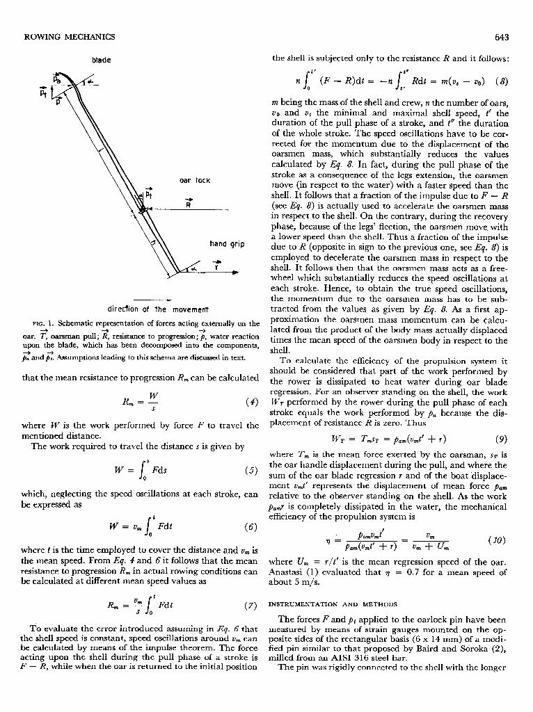
The forces acting upon each oar are (Fig. 1): I) The reac- tion j of the water against the blade. Of this force one com-
ponentpa has the same direction of the shell movement and it is therefore useful to progression. A second component fit is perpendicular to this direction; its effect is a strain on the shell, which is of no use for progression. 2) The force exerted by the rower T, which, as a first approximation, may be considered as having the same direction of the boat move- ment. 3) The resistance to progression R for each oar, considered as being applied to the oarlock pin, which is rigidly bound to the shell. 4) The oarlock reaction Pt to the force p, .
The simplifications introduced in such a schema are: a) The reaction exerted by the water upon the blade is considered as perpendicular to the oar axis. In practice, its direction changes with the position of the oar, as the pressure distribution on the blade is not uniform. b) The force T exerted by the rower is considered as parallel to the shell axis, while its inclination ranges within about zero and five degrees.
The rotatory movement of the oar is possible when the torque generated by the force T about the oarlock axis is equal or greater than the torque about the same axis generated by the force p
Thecos CY > p I - (1)
where a! is the rotation angle, h is the oar handle length, and I is the oar shaft length (Fig. 1).
Our force measuring device allows the determination as a function of time of the oarlock pin reaction components in the direction of the shell axis and its perpendicular. Thus we measure the overall propulsive force F applied to the oarlock
F= T +pa
and the transverse component of water reaction.
(2)
pt = p sin a! (3)
The overall propulsive force F is pulsatory, while the re- sistance to progression R (for each oar) would be constant if the shell speed were constant. In effect, due to the pulsa- tory characteristics of the propulsion mechanism, the shell speed cannot be constant but oscillates around a mean value ti, , depending upon the mass of shell and crew and the impulse of force F.
The work performed by F and R during a number of complete rowing cycles to travel the distance s must be the same for energy conservation, neglecting the mass and defor- mation of the oar and the friction of the oarlock. It follows
642
ROWING MECHANICS
oar lock
WP
dire&on of the movement
FIG. 1. Schematic representation of forces acting externally on the + + +
oar. T, oarsman pull ; R, resistance to progression; p, water reaction upon the blade, which has been decomposed into the components,
p: and pz Assumptions leading to this schema are discussed in text.
that the mean resistance to progression R, can be calculated
W R, = -
S (4)
where W is the work performed by force F to travel the mentioned distance.
The work required to travel the distance s is given by
s
8
W = Fds (5) 0
which, neglectin be expressed as
.g the speed oscillations at each stroke, can
s
t
W = v, Fdt (6) 0
where t is the time employed to cover the distance and vm is the mean speed. From Eq. 4 and 6 it follows that the mean resistance to progression R, in actual rowing conditions can be calculated at different mean speed values as
R, = ?!! s t Fdt s 0 (7)
To evaluate the error introduced assuming in Eq. 6 that the shell speed is constant, speed oscillations around vm can be calculated by means of the impulse theorem. The force acting upon the shell during the pull phase of a stroke is F - R, while when the oar is returned to the initial position
643
the shell is subjected only to the resistance R and it follows:
n s
” (F - R)dt = -n Ita Rdt = m(vt - vo> (8) 0 t’
m being the mass of the shell and crew, n the number of oars, vo and vt the minimal and maximal shell speed, t’ the duration of the pull phase of a stroke, and t” the duration of the whole stroke. The speed oscillations have to be cor- rected for the momentum due to the displacement of the oarsmen mass, which substantially reduces the values calculated by Eq. 8. In fact, during the pull phase of the stroke as a consequence of the legs extension, the oarsmen move (in respect to the water) with a faster speed than the shell. It follows that a fraction of the impulse due to F - R (see Eq. 8) is actually used to accelerate the oarsmen mass in respect to the shell. On the contrary, during the recovery phase, because of the legs’ flection, the oarsmen move. with a lower speed than the shell. Thus a fraction of the impulse due to R (opposite in sign to the previous one, see Eq. 8) is employed to decelerate the oarsmen mass in respect to the shell. It follows then that the oarsmen mass acts as a free- wheel which substantially reduces the speed oscillations at each stroke. Hence, to obtain the true speed oscillations, the momentum due to the oarsmen mass has to be sub- tracted from the values as given by Eq. 8. As a first ap- proximation the oarsmen mass momentum can be calcu- lated from the product of the body mass actually displaced times the mean speed of the oarsmen body in respect to the shell.
To calculate the efficiency of the propulsion system it should be considered that part of the work performed by the rower is dissipated to heat water during oar blade regression. For an observer standing on the shell, the work MJT performed by the rower during the pull phase of each
stroke equals the work performed by p, because the dis- placement of resistance R is zero. Thus
MjT = T,sT = pmr&ntl + r) (9)
where T, is the mean force exerted by the oarsman, ST is the oar handle displacement during the pull, and where the sum of the oar blade regression r and of the boat ‘displace- ment vmt’ represents the displacement of mean force jam relative to the observer standing on the shell. As the work p,,,~ is completely dissipated in the water, the mechanical efficiency of the propulsion system is
. p&J’ q = pa&J + r) = v, 1c” urn (10)
where U,,, = r/t’ is the mean regression speed of the oar. Anastasi (1) evaluated that r) = 0.7 for a mean speed of about 5 m/s.
INSTRUMENTATION AND METHODS
The forces F and p, applied to the oarlock pin have been measured by means of strain gauges mounted on the op- posite sides of the rectangular basis (6 x 14 mm) of a modi- fied pin similar to that proposed by Baird and Soroka (2), milled from an AISI 316 steel bar.
The pin was rigidly connected to the shell with the longer

side of the basis parallel to the shell axis. The measuring bridges consisted of two Philips PR 9833 K/03 SE strain gauges and two precision 120-Q resistors connected to miniature, battery-powered, signal conditioners mounted on the shell.
The oar position was recorded by means of a lOO-kQ linear radio potentiometer, mounted on the oarlock pin and powered by a 1.4-V dry battery.
All the electrical connections were insulated by means of a polyester paint and synthetic plaster Philips PR 9248/00.
The outputs of all transducers were directly connected to an oscillographic recorder Honeywell model 1706, em- ploying BB 160 A galvanometers with a linear response over the O-100 Hz range. The recorder was battery powered by means of an inverter and mounted on a motorboat following the shell. The connection with the apparatus on the shell was made by means of a ZO-m-long shielded wire. During the runs the wire was kept out of the water in order not to increase the resistance to progression.
The shell was an Olympic two-oared shell with coxwain, built in 1966 by Cantieri di Donoratico. The subjects were four well-trained athletes, two of them having taken part to the 1968 Olympiads. The registration was performed during a run about 100 m long at different predetermined rowing frequencies. During the experiments the wind speed was lower than 1 m/s.
The strain measuring bridges have been calibrated statically blocking the oar blade and applying known forces to the handgrip. Such a method allows the calibration either as a function of the pull T or of the overall force F as defined by Eq. 1.
EXPERIMENTAL RESULTS
Axial force measurements. From the record of the axial force F as a function of time (Fig. 2), the work required to over- come the resistance R has been calculated from Eq. 6 measuring all the complete rowing cycles performed during the runs in about 100 m.
When the rowing technique is not good and the oar is immersed or extracted from the water at a speed lower than that of the boat, as in the case of athlete Mu, a braking effect arises. As a result a negative work is performed by the rower.
0 1 2 3 4 5 6 7 t(sec) *
FIG. 2. Actual record of axial force F transverse force Pt and oar position angle CT as a function of time.
CELENTANO, CORTILI, DI PRAMPERO, AND CERRETELLI
log Vm <m/s>
-- 5
FIG. 3. Logarithmic plot of the resistance to progression R as a function of mean speed um. Different symbols occurring here and in other graphs refer to different athletes (see Table 1).
From the work M/ the mean resistance &, to progression can be calculated as from IQ. 7: this has been plotted in Fig. 3 as a function of the shell mean speed vm . The data in Fig. 3 can be interpolated by the equation
R m= KU a m UI)
where when R is given in newton and vm in m/s, K = 4.7 & 1.0, and a = 1.95 =t 0.49. The linear correlation co- efficient of the regression line of Fig. 3 is 0.82.
The power necessary to maintain the boat progressing (I@) is given by the product of the rowing frequency (f) and the work performed per stroke (w) and it is equal to the resistance times the mean speed of progression:
W = tuf = Rmvm W)
From Eq. 11 and 12 it follows that:
Eq= 12 and 13 correlate the mean speed of progression, the rowing frequency, and the useful work per stroke.
The experimental data of um , f> and w given in Table 1, for the two Olympic subjects are presented also in Fig. 4, A-C. These graphs represent the projections on the three Cartesian planes cf, urn), cf, w), and (v, , w) of experimental points and of the interpolating curve in space (f, um, w) as
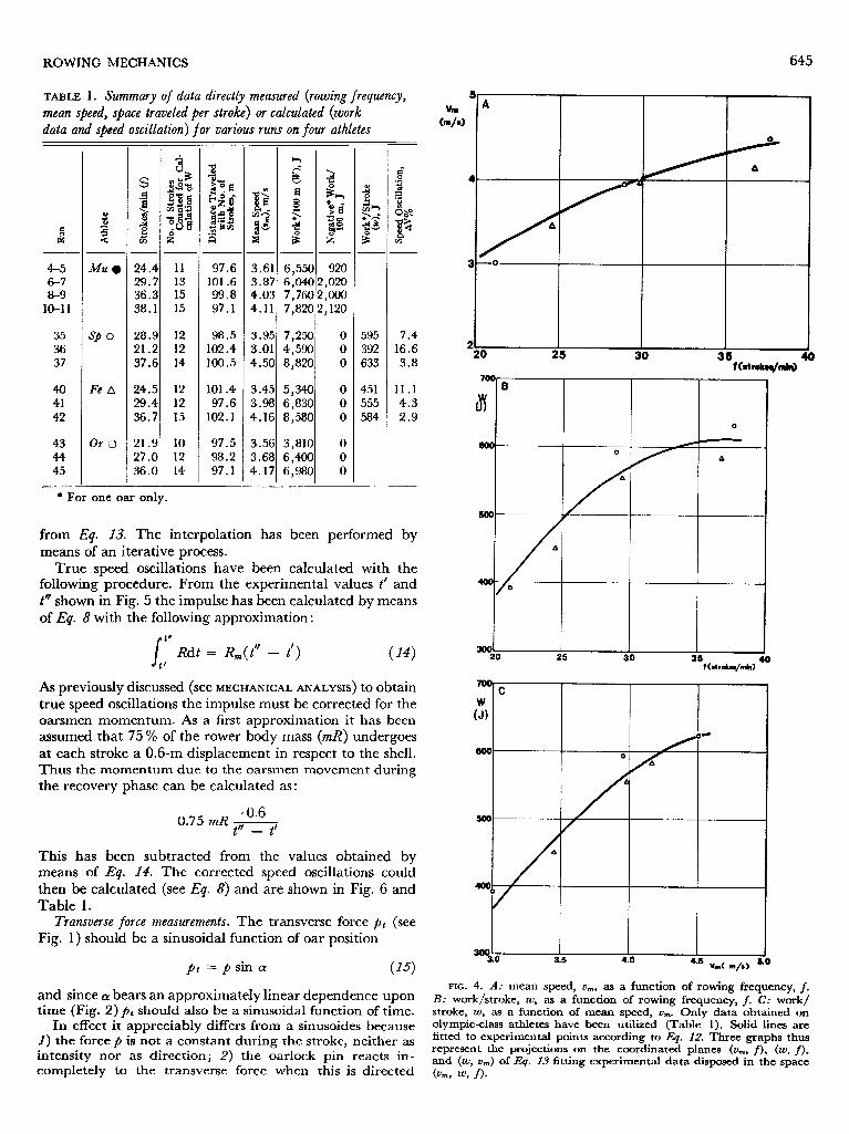
ROWING MECHANICS 645
TABLE 1. Summary of data directly measured (rowing frequency, mean speed, space traveled per stroke) or calculated (work data and sbeed oscillation) for various runs on four athletes
A J - - - - - 4
8% &Iwo 2-p :a .u v G
11 13 15 15
12 12 14
12 12 15
10 12 14
- 97.6
101.6 99.8 97.1
3.61 3.87 4.03
6,550 6PQ 7,760 7,820
98.5 102.4 100.5
4.11
3.95 3.01 4.50
7,250 4,590 8,820
101.4 3.45 5,340 97.6 3.98 6,830
102.1 4.16 8,580
97.5 3.56 3,810 98.2 3.68 674Qo 97.1 4.17 6,980
24.4 29.7 36.3 38.1
28.9 21.2 37.6
24.5 29.4 36.7
21.9 27.0 36.0
- .
595 7.4 392 16.6 633 3.8
451 11.1 555 4.3 584 2.9
SP 0
Fe A
Or Cl
920 2,020 WOO 2,120
4-5 6-7 8-9
lo-1 1
35 36 37
40 41 42
43 44 45
* For one oar only.
from Eq. 13. The interpolation has been performed by means of an iterative process.
True speed oscillations have been calculated with the following procedure. From the experimental values t’ and t” shown in Fig. 5 the impulse has been calculated by means of Eq. 8 with the following approximation:
s t* Rdt = R*(t” - tl> ( 14) t’ As previously discussed (see MECHANICAL ANALYSIS) to obtain true speed oscillations the impulse must be corrected for the oarsmen momentum. As a first approximation it has been assumed that 75 % of the rower body mass (mR) undergoes at each stroke a 0.6-m displacement in respect to the shell. Thus the momentum due to the oarsmen movement during the recovery phase can be calculated as:
I 30030
I I . 3.5 4.0
4*s Vm( m/o) 8
-
4 0.6 0.75 mR I/
t - t’
This has been subtracted from the values obtained by means of Eq. 14. The corrected speed oscillations could then be calculated (see Eq. 8) and are shown in Fig. 6 and Table 1.
Transverse force measurements. The transverse force fit (see Fig. 1) should be a sinusoidal function of oar position
pt =psin a! (15) FIG. 4. A: mean speed, u m. as a function of rowing frequency, f-
B: work/stroke, w, as a function of rowing frequency, f. C: work/ stroke, w, as a function of mean speed, urn. Only data obtained on olympic-class athletes have been utilized (Table 1). Solid lines are fitted to experimental points according to Eq. 12. Three graphs thus represent the projections on the coordinated planes (v,,,, f), (w, f>, and (w, v,) of Eq. 13 fitting experimental data disposed in the space (Cm9 W9 f>-
and since Q! bears an approximately linear dependence upon time (Fig. 2) pt should also be a sinusoidal function of time.
In effect it appreciably differs from a sinusoides because I) the force p is not a constant during the stroke, neither as intensity nor as direction; 3) the oarlock pin reacts in- completely to the transverse force when this is directed

CELENTANO, CORTILI, DI PRAMPERO, AND CERRETELLI
I
0 25 30 35 f(strokes/min)
40
FIG. 5. Duration of the stroke in seconds as a function of the rowing frequency. Dotted line: total cycle; continuous line: null phase.
2l Ar%
x
lt
s
a
)-
i- I 4
. Lo
I I I 25 30
35 t(8trokn/~
FIG. 6. Speed fluctuation in percentage of average speed (A u%), as a function of the rowing frequency. Speed fluctuations were cal- culated according to Eq. 14.
inward, since the oar collar is not compressed against the oarlock and the force is partly absorbed by the rower him- self.
In Fig. 7 the maximum outward force p, , perpendicular to the shell axis, is plotted as a function of the overall force F exerted in the same instant; the angle a! of the oar being in that moment, about 16”.
From Fig. 1:
P a = p cos CY (16)
and from Eq. 2 and 16
F=pcosa+ T (17)
30 - pt
Ckgl
20-
F sin4
1 0 cosdt-
h COSA 0
0
A kd
A A
/ 00
10 N-
0 2.0 60 80 F(kg) 100
FIG. 7. Transverse force fit as a function of axial force F. Actual pt,/F ratio is higher. than the limiting value calculated by Eq. 19 because the geometry of the oar-outrigger complex employed in our experiments did not satisfy the assumptions upon which Eq. 19 is based. Points on straight line, Olympic athletes; higher points, lower class athlete.
From Eq. 15 and 17 it follows that:
Pt p sin a sin a! F= p cos a + T = cos a + T/p ( 18)
and substituting T/p with the value obtained from Eq. I
Pt sin a! F= cos a + Z/h cos a ( 19)
Thus, for a given oar the wasted fraction of the propulsive force depends only upon its angular position, as Z/h is constant. It has been found that in all subjects the outward- ship force is maximum when the oar inclination is about 13” - 16”, and since in our oars Z/h = 2, from Eq. 19 the theoretical value of the ration pJF can be calculated as 0.11. The actual value given by the slope of the line in Fig. 7 amounts to 0.22, for the two better subjects. Other experi- mental points obtained on a lower class rower are even higher. This discrepancy will be discussed further.
GENERAL DISCUSSION
Accuracy of measurements. The work performed by force F has been calculated by Eq. 6 under the assumption that the speed is constant. In effect the speed increases during the pull and consequently the function F = f(s) is not symmetrical as is the function F = F(t) of Fig. 2. This’ how- ever does not significantly affect the area under the curve F = f(s). Moreover Fig. 6 shows that the total speed oscillation is negligible at rowing frequencies over 30 strokes/min. Thus we can conclude that our determination of R is a good estimation of total water and air resistance during actual rowing.
Transverse-to-axial force ratio. As mentioned above the ratio p JF obtained from experiments is appreciably higher than the maximal limiting value of 0.11 as calculated from Eq. 19. This can be ascribed to two different reasons. The assumption that the water reaction p is perpendicular to the

ROWING MECHANICS
oar axis is probably incorrect; this, however, cannot ac- count for the discrepancy between theoretical and experi- mental values of p,/F. For instance, an error of the order of lo”, would lead to a change of this ratio not greater than 0.03. Another much more important reason rests on the assumption that the force T exerted by the athlete is directed along the axis of the shell while in effect it is directed slightly outward, against the oarlock pin.
A 5” inclination of the force T can account for a twofold increase of the value p,/F as found in the better athletes. It is very likely that the worst athlete pulls the oar with an even greater inclination. This appears to be of great im- portance for a good performance in rowing as an unduly high inclination of the pull leads to a noticeable energy dissipation (3). The direction of the pull T is sensibly con- ditioned by the length of the oar handle, which, for this reason, must be individually adjusted to the anthropo- metric parameters of each athlete.
The transverse component pt of the reaction has been measured during the terminal phase of the stroke, because in the initial phase it is directed inward and is only partially counteracted by the oarlock. In fact, the oar bears a single collar internally to the oarlock. It follows that when the oar is pulled inward, the force is partly absorbed by the athlete, who should be trained to pull properly, not too hard or too long, to avoid too great energy waste.
On this basis a suggestion can be made, i.e., use a double collar internal and external to the oarlock to counteract the transverse force whatever its direction.
Eficiency of progression. A given amount of work per unit time can be obtained with different rowing frequencies and/or work per stroke (Eq. 12). However, at low rowing frequencies the speed fluctuations are high, Fig. 6, and
REFERENCES
1. ~ASTASI, A. Note sulla meccanica della voga. II Canottaggio, vol. 7, pp. 254-261, 1953.
2. BAIRD, E. D., AND W. W. SOROKA. Measurement of force-time relations in racing shells. Proc. Sot. Exptt. Stress Anal. 10 : 77-86, 1952.
because of the nonlinear relationship between speed and resistance (Eq. II-), it can be expected that the energy waste associated with speed fluctuations is higher the lower the frequency.
The mean power (V&J required to move the shell at urn = 4.5 m/s accounting for speed oscillations has been calculated by means of mean definition, as
s v2 k( a+1 V )d V
wrn= v1 V2 - Vl
where k and a + 1 are given the same values as in Eq. 13 and vl, v2 are the minimum and the maximum shell speed during each stroke (as from Fig. 6). It has been found that varying the rowing frequency from 20 to 50 strokes/min (at constant mean speed), and thus varying the speed oscillations v2 - v1 as by Eq. 12and 8, the difference between the two mean powers Wm is less than 4 %.
The conclusion can be reached that the overall efficiency of the exercise can be increased by increasing the strokes frequency, but the limits set by the speed of contraction of the muscles have to be carefully considered. In effect, Fig. 5 shows that Olympic-class athletes tend to maintain a fairly constant pull duration over a wide range of rowing fre- quencies.
The authors are indebted to Mr. Albert0 Zamboni and Mr. Carmine Romata for their technical assistance and to Dr. Ing. Giancesare Belli (Institute of Mathematics, Politechnic of Milan) for useful discussions and suggestions).
This study was supported by grants from the Federazione Italiana Canottaggio.
Received for publication 27 November 1972.
3. DI PRAMPERO, P. E., G. CORTILI, F. CELENTANO, AND P. CERRETELLI. Physiological aspects of rowing. J. Appt. Physiot. 31: 853-857, 1971.