Embed Size (px)
DESCRIPTION
this is the final design of a particular shaft in engine. Additionally, this is the an assignment assigned within the UWA for the mechnical design unit MECH3403. It shows steps and consideration of different factors considered when designing shafts, stresses involved.
Citation preview

MECH3403 – Assignment 1
Shaft Design
Prepared by
Group 52
Robin Kwan - 2089 2346Thanh Cong Le - 2087 2108
Mu Hua Sun - 2074 6066
March 2013

P a g e | 1
Table of Contents1.0 Introduction.....................................................................................................................................2
2.0 Specifications...................................................................................................................................3
2.1 Simplifications and Assumptions 2.1.1 Assumptions..............................................................3
2.1.2 Simplifications.......................................................................................................................4
3.0 Calculations.....................................................................................................................................4
3.1 Gear Ratio....................................................................................................................................4
3.2 Central Line Distance...................................................................................................................4
3.3 Bending moment and shear force analysis..................................................................................5
3.4 Shear stress analysis....................................................................................................................6
3.5 Power and torque........................................................................................................................6
3.6 Von Mises stress analysis.............................................................................................................6
3.6.1 Minimum shaft diameter......................................................................................................6
3.7 Deflection....................................................................................................................................6
4.0 Material Selection............................................................................................................................7
5.0 Bearings...........................................................................................................................................7
6.0 Program subroutine.........................................................................................................................8
7.0 Technical Drawing.........................................................................................................................13
8.0 Responsibilities..............................................................................................................................13
9.0 References.....................................................................................................................................14

P a g e | 2
1.0 IntroductionA certain company produces gear trains for different applications with different power input and rotational speeds. Consequently, the dimensions of shaft II will vary to adjust to these varying requirements. Our focus for this project is to design shaft II of the gear train. Shaft II is supported horizontally by two bearings and carries two gears (as shown). We are asked to develop a procedure program that determines the minimum shaft diameter when the user inputs their desired design parameters of a specific range. The program also is required to plot the distribution of the bending moment, torque, force and deflection along the shaft, and also a distribution of von Mises stresses along the shaft. We are also asked to select rolling-element bearings for shaft II and include general technical drawing of the shaft containing all key information for manufacturing.
Figure 1

Figure 2
P a g e | 3
2.0 Specifications
Power 1000 W – 1500W
Rotational Speed 1000 rpm – 2000rpm
Gear teeth (small) 15 teeth
Gear teeth (large) 45 teeth
Shaft II length 160 mm
Bearing distance from gears 30 mm
Pressure angle 25 degrees
Module 5 mm
2.1 Simplifications and Assumptions
2.1.1 Assumptions- Assume 100% efficiency of the gear train (i.e. no energy losses)- Disregard inertia effects

P a g e | 4
- Disregard fatigue failure mechanism, and use failure by yielding (von Mises Failure Theory)
- 15 000 life hours for bearings- 98% reliability for bearings
2.1.2 Simplifications
For this project we have selected a safety factor of 2. This is due to any safety factor higher than this value is deemed a waste of material and cost ineffective as the safety factor influences our minimum diameter of the shaft and therefore causing wastage of excess material needed for our situation.
3.0 Calculations
3.1 Gear Ratio
Gear ratio ‘e’ is bound by the equation,
e=number of driving teethnumber of teethdriven
Therefore,
e=1545
=13
Thus we get a gear ratio of13 . This is the same for the other pair of gears as we are told they
are identical pairs of gears with the same number of teeth in both pairs.
3.2 Central Line Distance
In order to work out the central line distance between the two co-linear shafts I & III and the shaft II, we need to determine the diameter of the gears.
By using the gear modulus equation,
m=diameter of gearnumber of teeth

Figure 3
P a g e | 5
We get,
diameter of gear (small)=m×number of teeth¿5×15¿75mm
Given that the modulus is the same for all gears,
diameter gear ( large )=5×45¿225mm
If we picture this in a diagram,
Central line=752
+ 2252
=150mm
We result in a central line of 150mm.
3.3 Bending moment and shear force analysis
As illustrated in the “Mathematical model of shaft design-section III”, bending moment analysis takes place in two different planes (i.e. X-Z plane and X-Y plane).This assumption is based on the present of the applied force by the motor when it rotates and produces torque along the shaft. The reason for us to consider in two planes is due to the pressure angle of 25o that causes the applied force to split into 2 components in X-Y and X-Z planes. The shear force can be found by differentiating the bending moment equations. Further calculation is clearly shown in “Mathematical model of shaft design-section III”.

Figure 4
P a g e | 6
3.4 Shear stress analysis
Due to the torsion caused by the rotational motor, there exists shear stress distribution that extends radially outwards from the centre of the shaft crossed section area and this shear stress reaches it maximum at the outer most layer of the shaft as shown in Figure 4. Further calculation of this maximum shear stress is shown in “Mathematical model of shaft design-section IV”.
3.5 Power and torque
Based on the assumption that the motor is 100% efficient, the power is theoretically transferred successfully along the shaft. That is power input will be equal to power output. Since the power is the same along shaft II, the rotational effect produces constant torques along shaft II with the two ends of the shaft II under opposite but equal torques. “Calculation of this value of Torque is shown in “Mathematical model of shaft design-section I”.
3.6 Von Mises stress analysis
Disregarding the failure of shaft due to fatigue as assumption shown above, yield strength is used to determine failure criteria. Applying distortion strain energy theory, Von Mises stress is then calculated and this stress value must always be less than the yield strength. In other words, the shaft will fail when Von Mises exceeds the yield strength of the material. A clearer analysis of Von Mises failure criteria are in “Mathematical model of shaft design-section V”.
3.6.1 Minimum shaft diameter From the Von Mises failure criteria, with some algebraic operations on the inequality between the Von Mises stress and yield stress, we can derive the formula for the minimum allowable shaft diameter before failure occurs. For safety purpose when design rotational shaft, safety factor can be added into the equation to obtain a more safe version of diameter. Full calculation is shown in “Mathematical model of shaft design-section IV”.

P a g e | 7
3.7 Deflection
Under loads, the shaft will deflect. The amount of deflection is complicated to analyse, so in order to obtain the deflection behaviour of shaft under loads, we have to derive it mathematically by applying simple beam theory to simplify all other complex cases. According to the theory, deflection can be expressed in term of pure bending moment along the shaft as shown,
EI d2 ydx2
=−M (x )
E and I are the modulus of elasticity and second moment of inertia. M(x) is the bending moment of shaft and y is the deflection distance from it neutral position. Full derivation is shown in “Mathematical model of shaft design-section VI”.
4.0 Material Selection
We are specifically asked to use mild steel as the material for the shaft. Due to mild steel having a small amount of carbon, it is softer and more easily shaped than higher carbon steels. This also means that it is ductile and not brittle therefore able to handle bending. It is also a lot cheaper than using steel and also better than using iron. It is cheap and also versatile making it an optimum choice.
We selected the 1030 grade mild steel due to its mechanic properties and slightly higher yield strength over the 1020 grade.
Mechanical Properties Tensile Strength (MPa) Yield Strength (MPa) Elongation (%)500 250 20
We also got a quote on the prices for our shaft on both grades of mild steel. Both grades are exactly the same costing an approximate $20 for the dimensions of our shaft.
5.0 Bearings
There are two bearings located on shaft two on the gear train. We assume it have a life of 15 000 hours and a 98% reliabililty and with the given inputs,
Inputs Values Outputs ValueInput power 1KW Diameter of shaft 13.4 mmRotational speed 12000 rpm Max shear stress 50.54 MPaSafety factor 2 Max normal stress 89.22 MPa

P a g e | 8
Yield strength 250 MPa Max BM in x-z plane 19.1 NmMax BM in x-y plane 8.91 NmTorque 23.87 Nm
Our selection of bearings depended on the load on the shaft and the type of forces involved. This led to a final decision of using ball bearings are they are suitable for both axial and radial forces. Since we know there are two bearings, the overall reliablility of the bearings will be,
R❑overall=R1×R2¿0.98×0.98¿0.9604≈96% In order to select our bearings, we need to
determine its basic dynamic load rating.
From the equation,
Lh=a1×( 106
60×n )× L4where :Lh=basic life rating∈hoursn=rotating speed (rpm )
L4=basic life of 96%reliabilitya1=reliablilty
And from the equation,
L4=(C r
P )3
where :C r=basic dynamic load rating (N )P=dynamic equivalent bearingload (N)
Substituing it in we get,
Lh=a1×( 10660×n )×(Cr
P )3
To get P,
¿calculatio n page ,P=F1 y+F2 y=R A' y+RB' y¿80 tan 25×Power
3ω A+ 80 tan 25×Power
ω A
¿949.952 N
Then rearranging for Cr ,
C r=(L4×60×na1×106 )
13×P¿( 15000×1200×6096×106 )
13×949.952¿2128.56 N¿2.13kN
Looking at the catalogue provided by NSK we selected the 6802 bearings.

P a g e | 9
6.0 Program subroutine
Our subroutine can only be run using MATLAB. It is not compatible with other software such as MATHEMATICA and EXCEL. The followings are step by step guide on how to use this subroutine.
1. Run MATLAB software and then open our m.file named “shaft_1”. Doing this will pop up an editor box.
2. On the top row of menu, click “run ‘shaft_1’” or simply press “F5” on your keyboard. A GUI that looks like figure () will shows up afterward. If a message box with several options appears, click “Add to Path”.
3. Insert the input parameter in the empty boxes in input panel and after that press “Compute” push button. Doing this will give you the bending moment, shear force and deflection diagram as well as other useful information.
4. Click the “Click here for other graphs” for viewing Von Mises stress and torque diagrams.
Figure () The layout of our GUI
Figure () The input panel on the top left side of our GUI.
Figure () This push button is located between input and output panels.

P a g e | 10
5. A sub-GUI will shows up and insert again the same input parameters to obtain the graphs. The sub-GUI will look like this.
Testing the subroutine:
Testing of the error dialog box
To prevent users from inserting out-of-range values for the inputs, a useful mechanism like error dialog box has been implemented to our subroutine. It warns users if users accidentally key in the wrong inputs. Various input values have been tested to verify its functionality and the table () is our test result. Status “Yes” means error dialog box appears and “No” means error dialog box does not appear.
Inputs: Status: Inputs: Status:Input Power = 900 W Yes Rotational speed = 500 rpm YesInput Power = 1250 W No Rotational speed = 1500 rpm NoInput Power = 1600 W Yes Rotational speed = 2001 rpm YesSafety factor = 0.5 Yes Safety factor = 2 NoSafety factor = 5 Yes
Testing of the graphs and output data
Our subroutine is tested with input data of following table and the tested result is shown in figure () and figure (). Table () also shows the output data for a given inputs.
Inputs Values Outputs ValueInput power 1.2 KW Diameter of shaft 15.13 mmRotational speed 1000 rpm Max shear stress 50.54 MPaSafety factor 2 Max normal stress 89.22 MPaYield strength 250 MPa Max BM in x-z plane 27.5 Nm
Figure () The layout of our sub-GUI
Table () The tested result of the error dialog box

P a g e | 11
Max BM in x-y plane 12.8 NmTorque 34.38 Nm
Table () Table above shows the tested outputs with certain inputs.

P a g e | 12
Figure () The graphs and outputs result.in sub-GUI

P a g e | 13
7.0 Technical Drawing
See end page.
8.0 ResponsibilitiesName Main ResponsibilityRobin Kwan -Programming
-Debugging-Research
Cong Thanh Le -Calculations-Bending , Shear, Power, Torque, von Mises, Deflection-Research
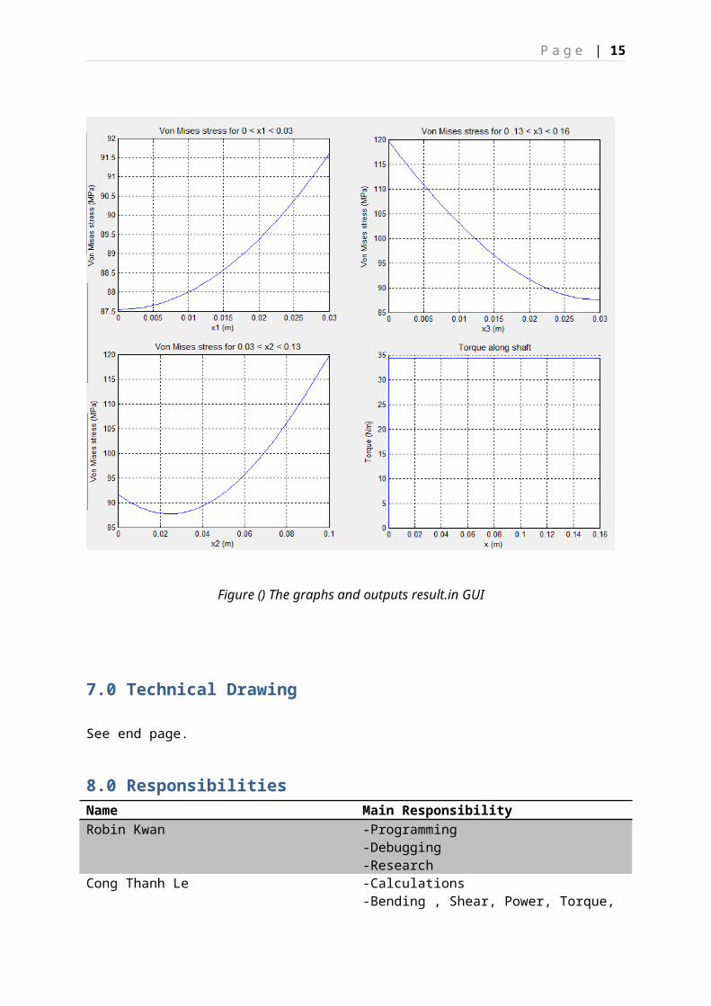
Figure () The graphs and outputs result.in GUI

P a g e | 14
Mu-Hua Sun -Gear ratio, Central line distance-Material, Bearing selection-Technical Drawing-Report
9.0 References
References:
Stephen J. Chapman, 2004, MATLAB Programming for Engineers, 3rd edition, Nelson, Thomson Canada Limited.
Desmond J. Higham & Nicholas J. Higham, 2000, MATLAB guide, Society for Industrial and Applied Mathematics Philadelphia.
Budynas, R. G. and Nisbett, J. K. Shigley’s 2008 Mechanical Engineering Design, 9thEdn, McGraw-Hill
Bӧhler Uddeholm (Australia) Pty Ltd ©2005, Bright Steels, viewed 24 March 2013, <http://www.buau.com.au/english/files/BMS.pdf>
Cixing Group Co. Ltd ©2008, Basic Rating Life, viewed 25 March 2013, <http://www.cwbearing.com/basic_ratinglife.html>
The Timkem Company ©2013, Bearing Life Calculations/Selection, viewed 25 March 2013,<http://www.timken.com/sites/newproducts/en-us/typee/Documents/Bearing_Life_Calculations.pdf>
NSK Ltd. Copyright ©, E1102k Rolling Bearings Catalogue, viewed 26 March 2013 <http://www.jp.nsk.com/app01/en/ctrg/index.cgi?rm=pdfView&pno=e1102k>
Mott Souders, Ovid Wallace Eshbach, 2001, Hand book of Engineering Fundamentals, 3 rd edition, Wiley Engineering handbook series.
P a g e | 15
Table of symbols used and their standard unitsFor calculation pages reference only
Meaning Symbol UnitPower input P W (Watt)
Angular velocity ω Rad per secTorque T Nm
Applied Force F NBending moment M Nm
Shear force V NShear stress τ Pa
Normal stress σ PaVon Mises stress σ VM Pa
Polar moment of inertia I P m4
Second moment of inertia
I m4
Shaft diameter d mYoung’s modulus E GPa
10^9 Pa