Embed Size (px)
Citation preview
01
taneously so that the mutual influence of neighboring com-ponents can be checked under different loading situations.
BackgroundThe high-voltage cables used in high-voltage vehicle electri-cal systems have, in addition to the HV inner conductor, a braided shield separated by insulation to avoid interference and radiation effects. The cylindrical structure of the high-voltage cables creates a capacitance between the HV inner conductor and the braided shield and thus a coupling path that is particularly sensitive to high frequencies. The current ripple in the inner conductor causes currents on the braided screen through inductive coupling. Since high voltages are switched in the high-voltage on-board power supply system during driving, high power and large currents are generated in the inner conductor. Between long cables that are close by, addition-al inductive coupling between the cable shields occurs as well. Another side effect caused by permanent shield cur-rents is premature aging, especially of the cable glands and their screwed joints due to high temperatures. The triangle springs supporting the braided shield inside the gland can also be destroyed by excessive currents.
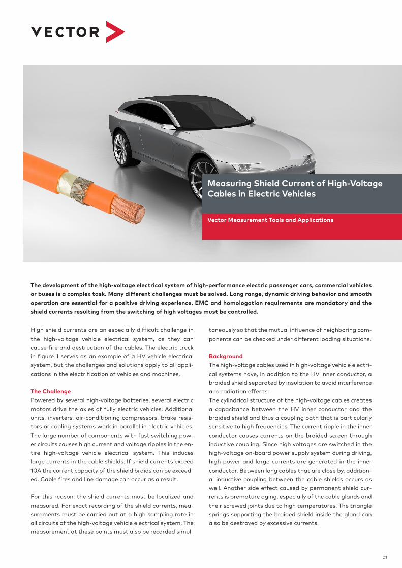
High shield currents are an especially difficult challenge in the high-voltage vehicle electrical system, as they can cause fire and destruction of the cables. The electric truck in figure 1 serves as an example of a HV vehicle electrical system, but the challenges and solutions apply to all appli-cations in the electrification of vehicles and machines.
The ChallengePowered by several high-voltage batteries, several electric motors drive the axles of fully electric vehicles. Additional units, inverters, air-conditioning compressors, brake resis-tors or cooling systems work in parallel in electric vehicles. The large number of components with fast switching pow-er circuits causes high current and voltage ripples in the en-tire high-voltage vehicle electrical system. This induces large currents in the cable shields. If shield currents exceed 10A the current capacity of the shield braids can be exceed-ed. Cable fires and line damage can occur as a result.
For this reason, the shield currents must be localized and measured. For exact recording of the shield currents, mea-surements must be carried out at a high sampling rate in all circuits of the high-voltage vehicle electrical system. The measurement at these points must also be recorded simul-
The development of the high-voltage electrical system of high-performance electric passenger cars, commercial vehicles or buses is a complex task. Many different challenges must be solved. Long range, dynamic driving behavior and smooth operation are essential for a positive driving experience. EMC and homologation requirements are mandatory and the shield currents resulting from the switching of high voltages must be controlled.
Vector Measurement Tools and Applications
Measuring Shield Current of High-Voltage Cables in Electric Vehicles

02
The SolutionThe solution is the Vector CSM e-Mobility measurement system. The HV cable network is distributed over the entire frame and chassis construction. A large number of HV aux-iliary units are wired to several HV batteries at the same time and switched on simultaneously during operation. For safe high-voltage measurement, CSM high-voltage break-out modules (HV BM) are permanently installed at all necessary points in the high-voltage vehicle electrical sys-tem. Each HV BM itself is provided with a potential equal-ization. The measurement of the shield currents is done via the HV BM’s measuring shunt.
For an accurate measurement, the shielding of the HV cable to the measurement shunt must be applied in the in-serted HV Breakout Modules. For this purpose, the coaxial shielding over the insulated inner conductor is disconnected and connected to the measurement shunt. Exact measure-ment results can only be achieved with a well-designed and low-resistance connection between braided shield and measurement shunt.
Figure 2: Construction of HV cables
Furthermore, it is necessary to install the entire measuring system in a high-voltage safe manner on the vehicle and to fix the measuring modules firmly to the frame. The mea-surement is carried out synchronously in all high-voltage circuits during a defined driving cycle on a dynamometer in order to obtain an accurate picture of the maximum shield currents. The individual shield currents must be sampled at a high sampling rate of 1MS/s in order to record all high- frequency shield current components and current peaks. Due to the simultaneous shield current measurement in all relevant high voltage lines, the verification on the chassis dynamometer need only be performed once.
With the measurement software vMeasure exp the numer-ous 1MS/s signals are acquired, visualized and analyzed online. The eMobilityAnalyzer used in vMeasure exp calcu-lates the effective current, apparent, active and reactive power as well as indirectly the heat generated in the shield from the recorded currents and voltages in real-time.
From the measurement in Figure 4 it can be deduced that the inner conductor current is opposed by a large shield current of up to 75A. vMeasure exp calculates the DC por-tion of the shield current with the eMobilityAnalyzer, but also the RMS value and the minima and maxima of the shield current. It is shown that although the average shield current is 0A, regular peak-to-peak values of up to 140A are measured. The effective current is calculated at 32A.The resistive losses in the shield, and thus the heat genera-tion, are proportional to the square of the calculated effective current (P ~ Irms²). The decisive factor here is the resistance coating of the shield, which usually has a small wire cross-section and a correspondingly high resistance coating. This can lead to a significant heating of the shield and thus of the cable.
HV Battery 1 HV Battery 2
HV Battery 3 HV Battery 4
PTO*
PTO*
HV
Pow
er D
istr
ibut
ion
Uni
t
Cooler
HV BreakingResisitor
HV BreakingResisitor
HV AC Compressor
Steering Pump
Air Compressor
ChargingSystem
Low-Voltage
Distribution
*Power take-off
HV Battery Distribution Unit
HV Inverter 1
HV Inverter 2
E-Motor 1
E-Motor 2
Figure 1: HV electrical system example

03
Figure 5 shows the course of the measured shield current as well as the calculated signals and the gain of informa-tion from the calculated signals. vMeasure exp generates new measurement signals online from the calculated val-ues, which can be further processed with all functions of vMeasure exp. The recording of the signals can be trig-gered. vMeasure exp allows the recording of selected sig-nals or the online calculated signals to limit the amount of stored data. The sample rate of the recording is flexible. The high-voltage breakout modules from CSM have been specially designed for safe measurement applications in live high-voltage lines in rough, mobile use. By selecting a suitable measurement shunt for current measurement and with the adjustable measurement ranges of voltage and current, the HV BM can be optimally configured for the measurement task. The HV BM 1.2 is used for high current lines from 125A to 800A. It allows two single-core HV lines to be connected to the breakout module. The HV BM 1.1 is suitable for two-core HV lines and loads up to 125A.
The Advantages > Innovative, fast, precise and flexible measurement for the validation and verification of the HV electrical system in the laboratory and in road tests > CSH’s HV Breakout Modules (HV BM) have been specially designed for safe measurement on high-voltage cables. Current and voltage are recorded synchronously in the HV BM. > The HV BM outputs the measured data (U, I) with a maximum data rate of up to 1MS/s (1μs), so that the requirement for the temporal resolution in the micro-second range is satisfied. > Synchronous recording includes not only all signals, but also signals from control units or the vehicle bus systems > The power of the vMeasure exp measurement software makes it easy to perform complex mathematical opera-tions on measurement channels during measurement. Thus, in addition to the recording of the measured signals, complex calculations such as the calculation of efficiency or the blind- and reactive powers can be done simultaneously and integrated into the recordings or visualized at the same time > The user can measure the current and voltage dynamics in the electric drive and receives immediate feedback during the driving test. > Seamless, automated analysis and professional repre-sentation of the measurement data is possible with the Vector vSignalyzer software tool > Direct transmission and secure storage of measured data can be done with the cloud-based Vector measure-ment data management system vMDM
Figure 3: Schematic Test setup with the Vector CSM E-Mobility measurement system
Figure 4: Current on the inner conductor and on the shield as well as calculated signals of the eMobilityAnalyzer
Figure 5: Same measurement as figure 4 but 30 seconds duration