Embed Size (px)
Citation preview

ICOMER
more intelligent management solution
A reliable partner in ICT Engineering
UbiGuard Solutions - FMS (Facility Monitoring Solution) - GDMS (Green Datacenter Management Solution) - RTLS (Real Time Location Solution) - AEMS (Atmosphere Environment Management Solution)
Other Solutions - SCACS(Smart Cold Aisle Containment Solution) - INNOWATCH(Video Monitoring Solution) - Water proof ceiling
Ubi G uard
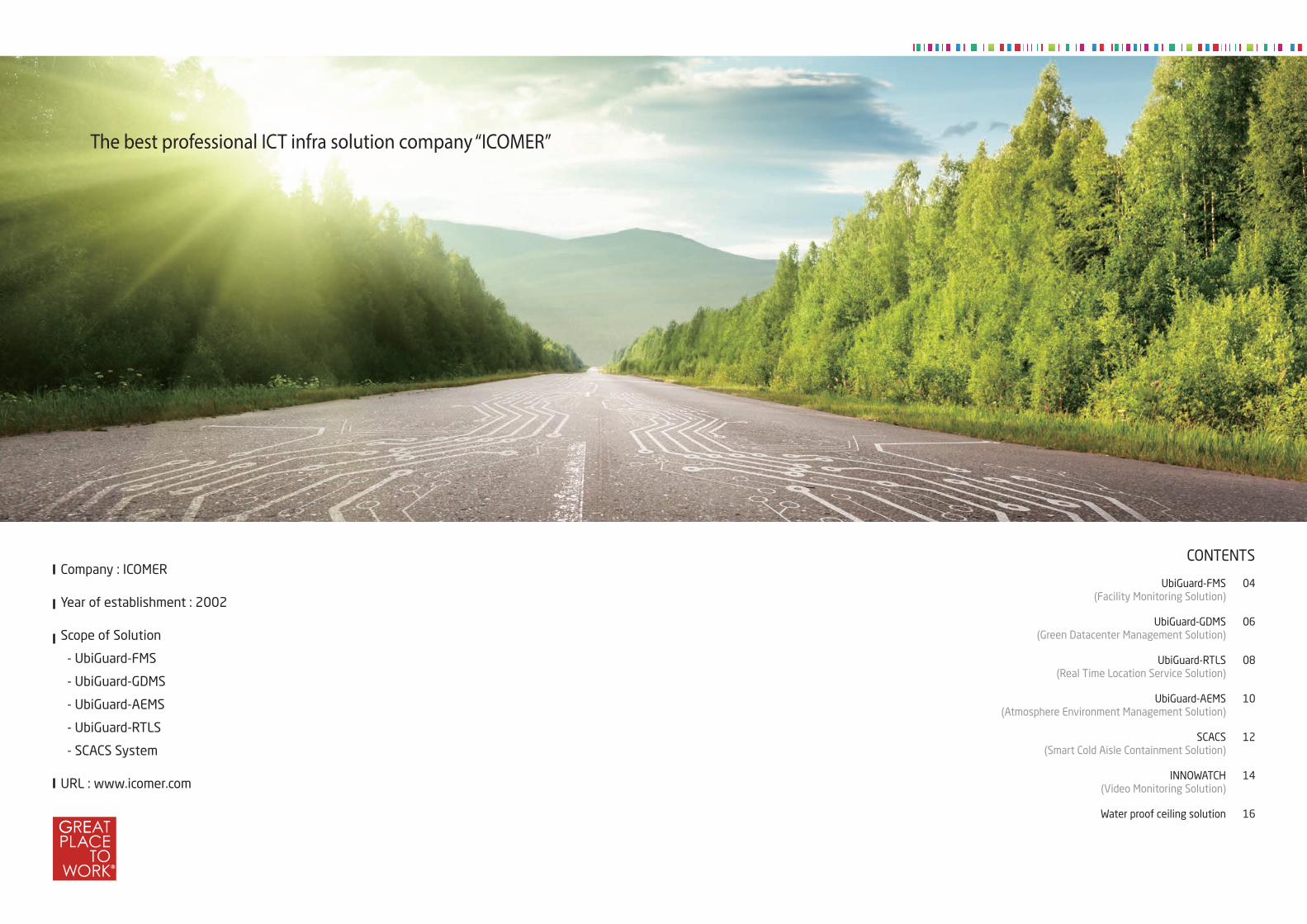
The best professional ICT infra solution company “ICOMER”
Company : ICOMER
Year of establishment : 2002
Scope of Solution
- UbiGuard-FMS
- UbiGuard-GDMS
- UbiGuard-AEMS
- UbiGuard-RTLS
- SCACS System
URL : www.icomer.com
UbiGuard-FMS(Facility Monitoring Solution)
UbiGuard-GDMS(Green Datacenter Management Solution)
UbiGuard-RTLS(Real Time Location Service Solution)
UbiGuard-AEMS(Atmosphere Environment Management Solution)
SCACS(Smart Cold Aisle Containment Solution)
INNOWATCH(Video Monitoring Solution)
Water proof ceiling solution
04
06
08
10
12
14
16
CONTENTS

Ubi G uard-FMS(Facility Monitoring Solution)
IntroductionFMS (Facility Monitoring Solution) solution monitors 24 hours a day, 365 days a year for the facility and the environment, such as telecom base stations or IDC (Internet Data Center).
Main control �eld
Category
UPS
Main monitoring contents
· Status info : input voltage/current/electric power, output voltage/current/electric power, charge and discharge current, battery voltage/current etc. · Warning : bypass, power outage, battery discharge, over-temperature, REC FUSE FAIL etc.
Thermo-hygrostat· Status info : action, fans, compressors, cooling, heating, humidi�cation, dehumidi�cation, water supply valves· Warning : compressor, heater, over-current, low-current, lack of water, over temperature, fans, water leak, sensor abnormality
Water leak · Status info : indication of water leak point· Warning : water leak
Power· Status info : R/S/T type voltage/current, power factor, all(current, voltage, electric energy), by circuit breaker (voltage, current, electric energy), amount of CO2 · Warning : alarm occurrences according to exceeded threshold
Temperature/humidity· Status info : temperature, humidity degree· Warning : alarm occurrences according to exceeded threshold
Access Control · Status info : access control system check· Warning : trespassing, equipment failure
CCTV · Status info : real-time video linkage, Pan/Tilt/Zoom in/out control· Linkage : automatic camera control by an event
04
Temperature/
Humidity
Data Gathering Device
WaterLeak
Sensor
Fire�ghting
PanelBoard Recti�er UPS UPS
Temperature/
Humidity
AccessControl CCTVHVAC
Security
Terminal Server
Dry Contact Serial TCP/IP TCP/IP
FMS Server
Network
Facility and environment control
Main screen
Management of equipment status and performance· Real-image, real-time status management· Real-time status management of multi level tree· Performance management of each facility· Storage of performance data
Report· Various type report· Analysis of alarm pattern through report· Flexible utilization of reports
Management of alarm· Various warning level (5-level)· Various alarm noti�cation(Pop-up, image, sound, SMS, E-mail)· Management of alarm history
Management of settings and rights· Facility and sensor-speci�c warning level setting· Level setting according to user authority· Facilities assignment according to each user
Asset Management· History of facilities input/modi�cation/query· Working history management of facilities
Server management· Monitoring of server status itself
Dashboard· Integrated control viewer
Mobile monitoring· Smart-mobile monitoring
Topology map
Group-hierarchy
Equipment-hierarchy
Zone-hierarchy
Shortcut button Warning status
Equipment information
Detailed monitoring list
Warning history
Menu
Main functions
05

GDMS is integrated green datacenter management solution which optimized for management and monitoring of power, HVAC equipment in order to stable and ef�cient operation of IT equipment in IDC(Internet Data Center)
Introduction
Optimization forHVAC
Ubi G uard-GDMS(Green Datacenter Management Solution)
SMS E-mailDashboard
CO2
Control center Server room User
Data center Container
GDMS Client GDMS Server
GDMS PAD
Server roomServer room
Dashboard GDMS ClientGDMS ClientGDMS ClientGDMS ClientGDMS ClientGDMS ClientGDMS ClientGDMS ClientGDMS ClientGDMS ClientGDMS ClientGDMS ClientGDMS ClientGDMS ClientGDMS ClientGDMS ClientGDMS ClientGDMS ClientGDMS ClientGDMS ClientGDMS ClientGDMS ClientGDMS ClientGDMS ClientGDMS ClientGDMS ClientGDMS ClientGDMS ClientGDMS ClientGDMS ClientGDMS ClientGDMS ClientGDMS ClientGDMS ClientGDMS ClientGDMS ClientGDMS ClientGDMS ClientGDMS ClientGDMS ClientGDMS ClientGDMS ClientGDMS ClientGDMS ClientGDMS ClientGDMS ClientGDMS ClientGDMS ClientGDMS ClientGDMS ClientGDMS ClientGDMS ClientGDMS ClientGDMS ClientGDMS ClientGDMS ClientGDMS ClientGDMS ClientGDMS ClientGDMS ClientGDMS ClientGDMS ClientGDMS ClientGDMS ClientGDMS ClientGDMS ClientGDMS ClientGDMS ClientGDMS ClientGDMS ClientGDMS ClientGDMS ClientGDMS ClientGDMS ClientGDMS ClientGDMS ClientGDMS ClientGDMS ClientGDMS ClientGDMS ClientGDMS ClientGDMS ClientGDMS ClientGDMS ClientGDMS ClientGDMS ClientGDMS ClientGDMS ClientGDMS ClientGDMS ClientGDMS ClientGDMS ClientGDMS ClientGDMS ClientGDMS ClientGDMS ClientGDMS ClientGDMS ClientGDMS ClientGDMS ClientGDMS ClientGDMS ClientGDMS ClientGDMS ClientGDMS ClientGDMS ClientGDMS ClientGDMS ClientGDMS ClientGDMS Client
· Measuring real-time wind speed, temperature, humidity
· Auto control for thermo-hygrostat, temperature, humidity/air volume with collected information
Optimization forelectric power
· Real-time monitoring for consumption of electric power such as voltage/current/power factor
· Real-time analysis for condition of power usage(each position, classi�cation)
· Central monitoring and analysis of over-load rack
PUE(Power Usage Effec- tiveness)
· Real-time PUE check, PUE change analysis in preparation for amount of electric power, analysis for amount of electric power by each equipment
· PUE gauge(level 2) = total incoming/distribution panel – (building HVAC power consumption + lighting, security, others) / panel board power consumption of server RM
Main functions
06
Main screen(C/S, PAD)
Expected effects
· Real-time monitoring of consumption of electric power for each panel board and rack
· Real-time analysis of consumption of electric power (each classi�cation, alarm factor and concentration monitoring of high load rack)
· Simpli�cation of repetitive routine work with various report con�rmation and print, automatic report function
Increase the ef�ciency of operating work
· Increase of system availability by real-time monitoring
· Preparation for similar alarm with existing data
· Pre-sensing symptom with setting alarm event
Accident prevention
· Henceforth, securing base on the volume rate accounting system each user and rack
· Expression like real equipment with 3D-screen, intuitive interface
· Ease to analyze with various and detailed report
Reinforcement of management and analysis function
GDMS Client SMART PAD
1
2
3
07

Structure diagram
Expected effects
RTLS Server
Anchor Anchor Anchor Anchor Anchor Anchor
Tag Tag Tag Tag Tag Tag Tag Tag Tag Tag Tag Tag
RTLS· In case of �re and gas leakage accident, realization of the visitor’s location and action
· In emergency situation, immediate reactions through its call function
Safety managementSecurity accident prevention
· Communicating the location and access information between security server and interface to warn and take action to abnormal access
· Strengthening security awareness with public relation of the real time location recognition system
Follow-up investigation
· Analyzing the visitor’s route to check security breach
· Prevention of accident recurrence through real time location trace of the visitor
· In case of security problem with the visitor, immediate investigation of the cause
Ubi G uard-RTLS(Real Time Location Solution)
POE Hub
1F 2F 3F
Menu
RTLS(Real Time Location Solution) is the solution which offers the location of speci�c object or personnel with attached RTLS tag in real time. It is built to realize the visitor’s access status, location information and route in limited access area. Finally the solution provides perfect security management to the visitor.
Introduction
08
Main display
※ When a tag is selected, the route will be displayed
Receiveapplication
Visitor’s visitapplication
Security levelsetting from
security dept.
Issue transmitteraccording tosecurity level
Move to visitingdepartment
Saving data ofvisitor’s route
Alarm for access toinaccessible area
Monitoringdata
Real time trace ofvisitor’s location
Scenario
Menu
09
Personnel situation
Alarm noti�cation
Optional information
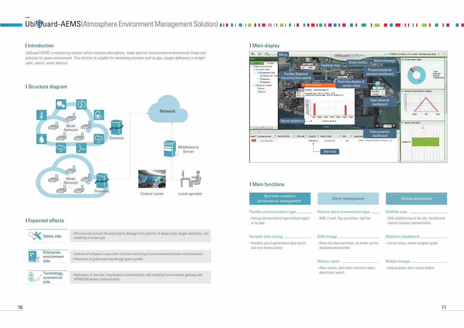
Ubi G uard-AEMS(Atmosphere Environment Management Solution)
Structure diagram
Expected effects
· Minimize and prevent life and property damage from pollution of danger area, oxygen de�ciency, and breathing of poison gasSafety side
· Enhance of company's value with real time monitoring of environmental pollution and prevention· Prevention of global warming through green growth
Enterprise, environmentside
· Realization of low cost, long distance communication with combined wire-wireless gateway and M2M(USN) sensor communication
Technology, economicalside
Local operatorControl center
Middleware/Server
Gateway
Gateway
MeshNetwork
MeshNetwork
CO
CO2
O2
Network
IntroductionUbiGuard-AEMS is monitoring solution which monitors atmosphere, water and soil and prevents environmental threat and pollution for green environment. This solution is suitable for monitoring sections such as gas, oxygen de�ciency in airtight room, stench, water and soil.
10
Main display
Main functions
· Various communication type without regard to its type
Real time condition, performance management
Various expressionAlarm management
Flexible communication type
· Practical use of performance data search and error history search
Periodic data saving
· SMS, E-mail, Pop-up window, light bar
Various alarm transmission type
· When the alarm activated, all screen will be displayed and recorded
DVR linkage
· Alarm search, daily alarm statistics report, data history search
History report
· With satellite map of the site, intuitive and realistic situation representation
Satellite map
· Current status, sensor progress graph
Statistics dashboard
· Data analysis, alarm status display
Mobile linkage
Facility/ Regionalhierarchy (tree panel)
Data progressdashboard
Total obstacledashboard
Present obstaclesituation dashboard
Topology mapAlarm message
Real time display ofsensor value
Menu
Alert list
Alarm statistics
Home button
11

Basic principle of smart cold aisle containment· Optimal coordination environment completely separated the cold and hot air as Containment
· Into Containment, the static pressure is maintained and constant air conditioning is supplied
· The existing return temperature sensing -> The supplying temperature of Containment inside sensing and operating
· Supplying the constant temperature to each Containment by air conditioning grill
Main construction
· Containment inside temperature/humidi-ty, PMS environment monitoring
· Swing/slide door, automatic close
· Ease to change without regard to height(�exibility), double warm/cold keeping effect
· Automatic open/close by �re �ghting linkage
· Anti-static, anti-fouling, prevention of scratch and decoloration
· Uninterruptible painting, 180℃lique�ed color painting
Smart PAD Door Blind Fire�ghting Rail Polycarbonate Painting
Smart PAD Blind
Door Frame
Fire �ghting Rail/Polycarbonate
Cold aisle containment reduces cold air bypass of the server inlet
Raised Tile Floor
CRA
C U
nit
CRA
C U
nit
Serv
er R
ack
Serv
er R
ack
Serv
er R
ack
Serv
er R
ack
The air �ow of existing system
SCACS(Smart Cold Aisle Containment Solution)SCACS is interlocked with the UbiGuard-GDMS
12
Structure diagram
Expected effects
· Reduction for power consumption of thermo-hygrostat by 20%
· Recovery in contrast to investment (ROI) average of 3.5 years
· In accord with government policy “Green Data Center Certi�cation”, competitiveness secures(PUE 2.3→ 1.8)
Energy reduction effects
· Optimized operating environment serving for computer facilities by supplying temperature and air to keep static pressure in Containment
· Due to reduction of the number of thermo-hygrostat operation, extension of the life and reduction of customer investment
· Extension the lifetime of IT equipment
· Prevention of global warming through the reduction carbon emissions
Technical effects
· By integrating control of temperature/humidity, power, secure facilities, increase of operational effectiveness
· Fault management and history management for load paradigm change through integrated intelligent management, fault management
· In future, demand prediction of facilities and history management of replacement cycle through assets and operating pattern analysis of facility resource
Operational effects
1
2
3
13
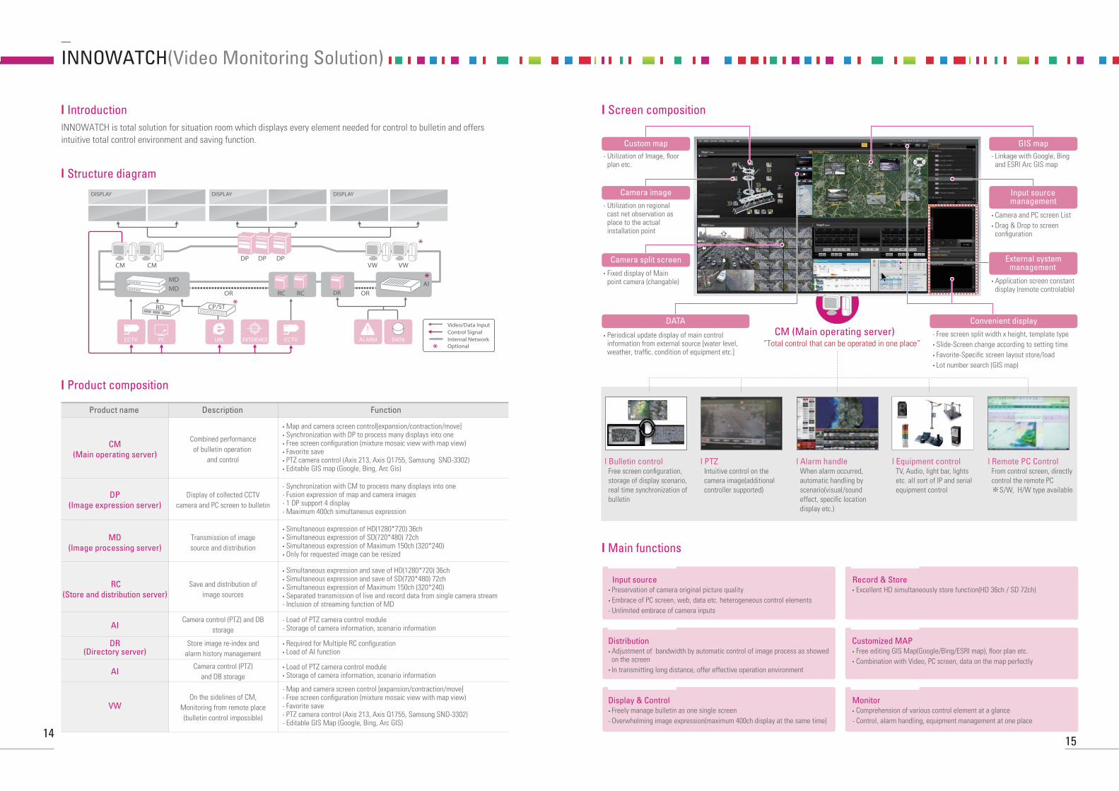
INNOWATCH(Video Monitoring Solution)
Introduction
Structure diagram
INNOWATCH is total solution for situation room which displays every element needed for control to bulletin and offers intuitive total control environment and saving function.
Product composition
Product name
CM(Main operating server)
Description Function
Combined performanceof bulletin operation
and control
· Map and camera screen control[expansion/contraction/move]· Synchronization with DP to process many displays into one· Free screen con�guration (mixture mosaic view with map view)· Favorite save· PTZ camera control (Axis 213, Axis Q1755, Samsung SND-3302)· Editable GIS map (Google, Bing, Arc Gis)
DP(Image expression server)
Display of collected CCTVcamera and PC screen to bulletin
· Synchronization with CM to process many displays into one· Fusion expression of map and camera images· 1 DP support 4 display· Maximum 400ch simultaneous expression
MD(Image processing server)
Transmission of imagesource and distribution
· Simultaneous expression of HD(1280*720) 36ch· Simultaneous expression of SD(720*480) 72ch · Simultaneous expression of Maximum 150ch (320*240) · Only for requested image can be resized
RC(Store and distribution server)
Save and distribution ofimage sources
· Simultaneous expression and save of HD(1280*720) 36ch· Simultaneous expression and save of SD(720*480) 72ch · Simultaneous expression of Maximum 150ch (320*240)· Separated transmission of live and record data from single camera stream· Inclusion of streaming function of MD
AICamera control (PTZ) and DB
storage· Load of PTZ camera control module· Storage of camera information, scenario information
DR(Directory server)
Store image re-index andalarm history management
· Required for Multiple RC con�guration· Load of AI function
AICamera control (PTZ)
and DB storage
VWOn the sidelines of CM,
Monitoring from remote place(bulletin control impossible)
· Load of PTZ camera control module· Storage of camera information, scenario information
· Map and camera screen control [expansion/contraction/move]· Free screen con�guration (mixture mosaic view with map view)· Favorite save· PTZ camera control (Axis 213, Axis Q1755, Samsung SND-3302)· Editable GIS Map (Google, Bing, Arc GIS)
MD
DP
RCOR ORRC DR
DP DPCM CM VW VW
MDAI
RD
PC URL EXT.DEVICE CCTVCCTV
CP/ST
DISPLAY DISPLAY DISPLAY
Video/Data InputControl SignalInternal NetworkOptional
ALARM DATA
14
Input source· Preservation of camera original picture quality· Embrace of PC screen, web, data etc. heterogeneous control elements· Unlimited embrace of camera inputs
Record & Store· Excellent HD simultaneously store function(HD 36ch / SD 72ch)
Distribution· Adjustment of bandwidth by automatic control of image process as showed on the screen
· In transmitting long distance, offer effective operation environment
Customized MAP· Free editing GIS Map(Google/Bing/ESRI map), �oor plan etc. · Combination with Video, PC screen, data on the map perfectly
Display & Control· Freely manage bulletin as one single screen· Overwhelming image expression(maximum 400ch display at the same time)
Monitor· Comprehension of various control element at a glance· Control, alarm handling, equipment management at one place
Screen composition
Main functions
Custom map· Utilization of Image, �oor plan etc.
· Linkage with Google, Bing and ESRI Arc GIS map
· Camera and PC screen List · Drag & Drop to screen con�guration
· Application screen constant display (remote controlable)
· Free screen split width x height, template type· Slide-Screen change according to setting time· Favorite-Speci�c screen layout store/load· Lot number search (GIS map)
· Utilization on regional cast net observation as place to the actual installation point
· Fixed display of Main point camera (changable)
Camera image
Camera split screen
GIS map
External systemmanagement
Convenient displayCM (Main operating server)
“Total control that can be operated in one place”
l Bulletin control Free screen con�guration, storage of display scenario, real time synchronization of bulletin
l PTZ Intuitive control on the camera image(additional controller supported)
l Alarm handle When alarm occurred, automatic handling by scenario(visual/sound effect, speci�c location display etc.)
l Equipment control TV, Audio, light bar, lights etc. all sort of IP and serial equipment control
l Remote PC Control From control screen, directly control the remote PC ※S/W, H/W type available
Input sourcemanagement
· Periodical update display of main control information from external source [water level, weather, traf�c, condition of equipment etc.]
DATA
15

Purpose of installation· Deterioration or ruptures of a fan coil pipe/air conditioning plumbing
· Damage to water pipes in the ceiling of the same �oor or an upper �oor
· Sudden operation of sprinkler �re extinguishing system due to the outbreak of �re
· Malfunction of sprinkler �re extinguishing system
· Dew condensation
· Blocking the dust
Principle of water proof ceiling· A waterproof panel of ceiling to block a water leak
· A drain module bar to create a �ow passage for leaked water
· A water collecting pipe to discharge the water
Sequence of construction
Installation of a lightweightceiling steel frame
Installation of adrain module bar
Attachment of Miton Leak test
Installation of awaterproof panel
Water proof ceiling solution
16
Main screen
· It is usually applied to a small computer room and its appearance is similar to the existing ceiling.
· It is easy to adjust ceiling height.
· The ability to absorb sound improves due to the attachment of Miton.
· Slim-type of light can be installed.
· A kinds of funiture(communication tray) can be installed through the ceiling by inserting perge inserts in the lower panel of the ceiling
· The space between a waterproof ceiling and an ordinary ceiling can be used for the passage of air circulation, so it is good for a large computer room or IDC center
· Air return grille whose size is the same to Miton can be partially installed on the area whose temperature is high
· It has an advantage in the case of having enough ceiling heights
· It is mainly used for computer room, power room, UPS room, and has an advantage when installing tray or duct, plumbing pipe.
· The lower part of the waterproof ceiling system exposes ceiling, so it is good to secure the ceiling height.
· After installation, lights can be installed by race way method, so are easy to be re-located.
Base-Type
Air Conditioning-Type
Equipment-Type
drain module bar
Mition line of lights
“C” CHANNEL
waterproofpanel
drain module
waterproof surfaceof the ceiling
installationof a duct
drain module bar
installationof tray
installationof plumbing
passage ofair circulation
ordinary surfaceof the ceiling
17

HR Development
R&D Investment
Customer Satisfaction
Improvement in Quality
Global Management
Smart, green and economical infra provider
ICOMER
SmartGreenEconomic
Design
Eco-friendly
Efficiency
ChangeChallengeCooperation
Passionate
Creative
Sharing
MISSION
MISSION
HUMAN
BUSINESSWith your continuing interest, ICOMER will become a global ICT service provider by achieving the vision of a green ICT and incorporating ICOMER’s core values.
Realization of values through individuals, team and enterprises
Realizing a vision of the future society
Creat
ion
of so
cial
val
ues
Custo
mer
Sat
isfa
ctio
n
With your continuing interest, ICOMER will become a global ICT service provider by achieving the vision of a green ICT and incorporating ICOMER’s core values.
Mission

iComer Co., Ltd.1-1003. Ace Hitech City, 55-20 Mullae-Dong 3-Ga,Yeongdeungpo-Gu, Seoul 150-972 Koreawww.icomer.comTEL : 82-2-466-3700, FAX : 82-2-466-3755
ICOMER is Yours
Think New !!