Embed Size (px)
Citation preview

MATERIALS FORUM VOL. 27 (2004) 68 - 73
© Institute of Materials Engineering Australasia Ltd – Materials Forum Volume 27 - Published 2004 68
MEASUREMENT OF FRACTURE TOUGHNESS OF HYDRIDED ZIRCALOY - 4
M. D. Callaghan1, W.Y. Yeung1, M. I. Ripley2, D.G. Carr2
1Department of Chemistry, Materials and Forensic Science, University of Technology, Sydney, P.O. Box 123, Broadway
NSW 2007, Sydney, Australia. 2Materials and Engineering Science, Australian Nuclear Science and Technology Organisation, Private Mail Bag 1,
Menai NSW 2234, Sydney, Australia. ABSTRACT Zircaloy-4 is a zirconium alloy that will be used for construction of many of the core components in the replacement research reactor at Lucas Heights. The fracture toughness of the alloy and its radiation-induced reduction over the 40 year planned life of the reactor is an important mechanical property for this application. This study aims to simulate the radiation-induced reduction in fracture toughness by hydriding Zircaloy-4. A range of fracture toughnesses is required to calibrate the sub-size Charpy and small punch (SP) surveillance specimens that will be irradiated over the life of the reactor against standard J1C fracture toughness specimens. Pieces of Zircaloy-4 plate were hydrided in a vessel at a temperature of 520°C, at different pressures for either 10 or 22 hours. Final hydrogen concentrations between 25 wt% ppm and 380 wt% ppm hydrogen were obtained under gaseous atmosphere. The fracture toughness of the hydrided Zircaloy-4 was assessed using sub-size 2.5 mm-thick Charpy, three-point bend J1C and SP tests. The results were correlated to determine the relationship between the J-integral fracture toughness, Charpy impact energy and equivalent fracture strain (εqf) from the SP tests. It was found that as hydrogen concentration and hydride formation increased, the fracture toughness of the alloy generally decreased. The results show there to be a useful relationship between fracture toughness and εqf measured for the SP tests. 1. INTRODUCTION During the service life of nuclear reactors, embrittlement of zirconium alloys used in reactor core components occurs as a result of fast neutron irradiation. Zircaloy-4 (Zr-4) is to be used in ANSTO’s replacement research reactor (RRR) for reactor core components, including reflector vessel, beam tubes and chimney. The fracture toughness of this alloy is an important mechanical property to be studied over the service life of the reactor as embrittlement of Zircaloy will detrimentally affect mechanical properties and performance of components. At present there is no irradiation embrittlement data for Zr-4 at RRR operating conditions. Hydrides are well known to cause embrittlement and reduce mechanical properties in zirconium alloys1-5. Therefore hydride embrittlement could be used as a surrogate embrittlement process to obtain various J1C fracture toughness values, in order to obtain correlations between J1C fracture toughness and Charpy v-notch impact and SP tests. There is a very limited volume available for surveillance specimens in the core of a nuclear reactor for analysis of radiation-induced changes and hydrogen absorption during service life. J1C fracture toughness and Charpy v-notch specimens use a large volume of material, whereas only small volumes of material are required for small punch specimens. The objective of this work was to define correlations between J1C
fracture toughness and Charpy v-notch and SP tests in order to make better use of the limited volume available in the RRR for surveillance specimens. 2. MATERIAL AND EXPERIMENTAL PROCEDURE 2.1 Material Test specimens were prepared from a hot rolled and annealed Zr-4 plate. Five Zr-4 pieces with dimensions 90 mm length, 90 mm width and 8.6 mm thickness were cut from the Zr-4 plate. 2.2 Hydrogen charging Four Zr-4 pieces were gaseous hydrogen charged in a vessel using pure hydrogen at a temperature of 520°C, for either 10 or 22 hrs at pressures of 0.5, 0.67 and 1.0 atm. The pieces were furnace-cooled to room temperature inside the vessel after charging. Hydrogen concentrations between 25 wt% ppm and 380 wt% ppm hydrogen were achieved. A LECO™ hydrogen analyser was used to measure hydrogen concentration. 2.3 Test specimens Test specimens for tensile, Charpy v-notch impact, fracture toughness and SP tests were prepared from each Zr-4 piece. Specimens were oriented transverse to the rolling direction of the Zr-4 plate. Tensile specimens were stamped to dimensions: length = 65
MATERIALS FORUM VOL. 27 (2004) 68 - 73
© Institute of Materials Engineering Australasia Ltd – Materials Forum Volume 27 - Published 2004 69
mm, width = 4 mm and thickness = 1 mm. Sub-sized 2.5 mm Charpy v-notch impact specimens were wire-cut to dimensions according to AS 1544.5-1981. Three point bend J1C specimens were wire-cut to dimensions: width (W) = 17.2 mm, thickness (B) = 8.6 mm in accordance with ASTM 1820-99a. The J1C specimens were fatigue pre-cracked to a crack length, ao = 0.6W. The SP specimens were initially wire-cut with dimensions: 10 mm diameter and 0.6 mm thickness. The SP specimens were ground to a final thickness of 0.500 mm ± 0.005 mm. 2.4 Experimental procedure Tensile testing was conducted according to AS 1391-1991, Charpy v-notch testing was conducted according to AS 1544.5-1981 and J1C testing was performed by evaluating J-R curves by the single-specimen unloading compliance technique on three point bend specimens, according to ASTM E1820-99a. SP testing was done using position control with a strain rate of 0.2 mm/min. All mechanical testing was done at room temperature. 2.5 Metallography and fracture analysis Specimens were hot mounted in clear resin and a standard mechanical polishing procedure carried out, using Kemlube as lubricant. Final chemical polishing using the solution in Table 1 was done to reveal hydrides in the Zr-4 structure.
Table 1. Chemical polishing solution.
Chemical Amount Hydrogen Peroxide (30%) 25 mL
Nitric acid (70%) 25 mL Hydrofluoric acid (48%) 8-10 drops
Polished specimens were examined using optical microscopy to investigate and compare the amount of hydride formation and hydride orientation. Scanning electron microscopy (SEM) analysis was used to observe both hydrides and fracture surfaces of J1C, Charpy v-notch and SP specimens. The SEM analysis was used in backscattered mode to observe hydrides and in secondary electron mode to observe hydrides and fracture surfaces. 3. RESULTS AND DISCUSSION 3.1 Hydride formation Optical microscopy and SEM revealed that hydrides with platelet morphology formed in the Zr-4 microstructure and confirmed previous research on hydride platelet formation by slow furnace cooling6,7 after hydrogen charging. Hydride platelets formed uniformly throughout specimens and were intergranular and preferentially oriented parallel to the rolling direction of the plate. Hydride platelet band formation was observed parallel to the rolling direction
of the 208 wt% ppm and 380 wt% ppm specimens and was thought to be due to low nucleation rates of hydrides and high diffusivity at slow cooling rates confirming the work of Hong et al.8. The amount of hydride platelets increased with increasing hydrogen concentration, but their size was found to be similar for all hydrogen-charged pieces. Hydride platelet thicknesses were approximately 1 µm, platelet lengths varied but were generally less than 25 µm. The hydride platelet dimensions at slow furnace cooling rates were similar to those found by Bai et al7.
Figure 1. Optical micrograph of hydride platelets and
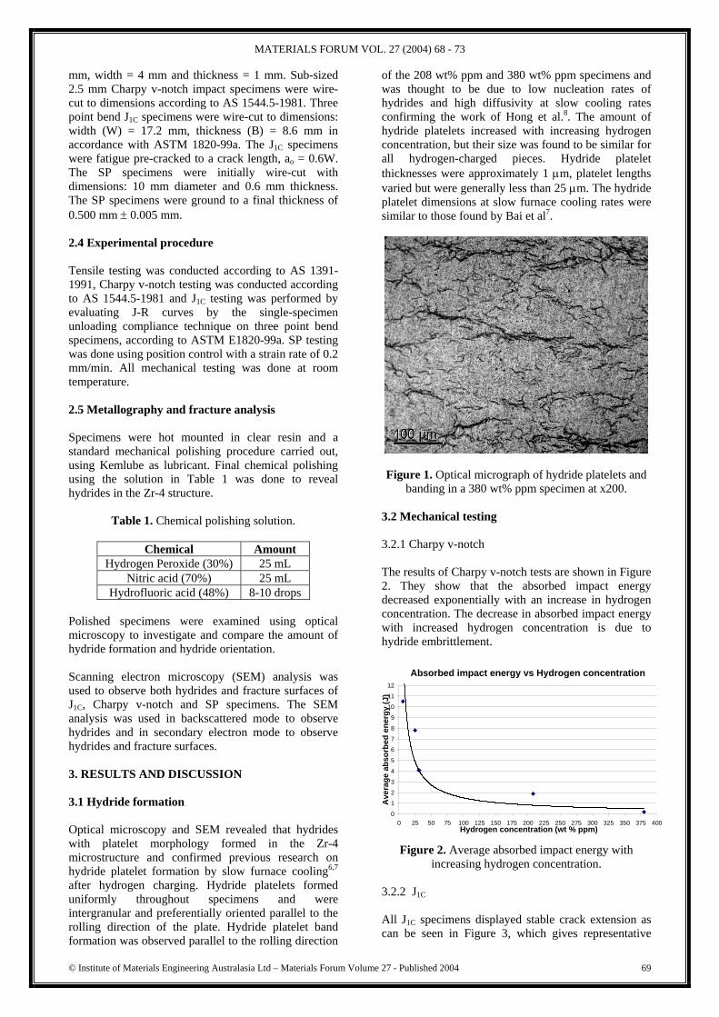
banding in a 380 wt% ppm specimen at x200. 3.2 Mechanical testing 3.2.1 Charpy v-notch The results of Charpy v-notch tests are shown in Figure 2. They show that the absorbed impact energy decreased exponentially with an increase in hydrogen concentration. The decrease in absorbed impact energy with increased hydrogen concentration is due to hydride embrittlement.
Figure 2. Average absorbed impact energy with increasing hydrogen concentration.
3.2.2 J1C All J1C specimens displayed stable crack extension as can be seen in Figure 3, which gives representative
Absorbed impact energy vs Hydrogen concentration
0
1
2
3
4
5
6
7
8
9
10
11
12
0 25 50 75 100 125 150 175 200 225 250 275 300 325 350 375 400Hydrogen concentration (wt % ppm)
Ave
rage
abs
orbe
d en
ergy
(J)
MATERIALS FORUM VOL. 27 (2004) 68 - 73
© Institute of Materials Engineering Australasia Ltd – Materials Forum Volume 27 - Published 2004 70
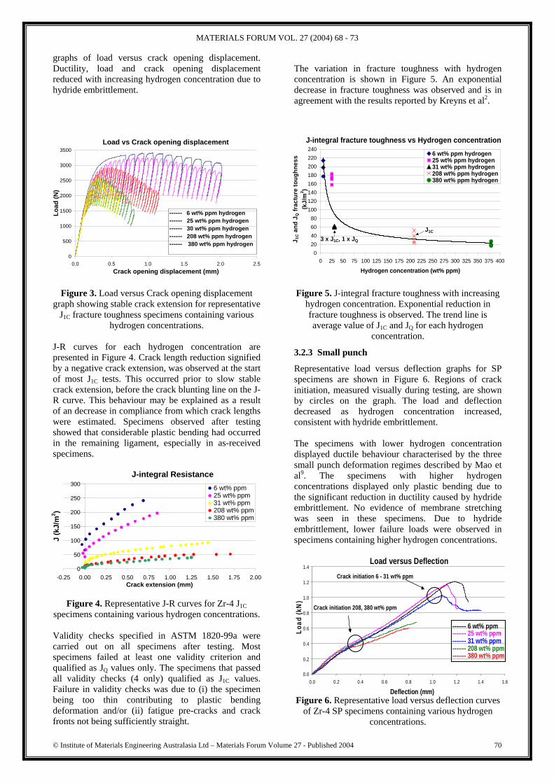
graphs of load versus crack opening displacement. Ductility, load and crack opening displacement reduced with increasing hydrogen concentration due to hydride embrittlement.
Figure 3. Load versus Crack opening displacement graph showing stable crack extension for representative
J1C fracture toughness specimens containing various hydrogen concentrations.
J-R curves for each hydrogen concentration are presented in Figure 4. Crack length reduction signified by a negative crack extension, was observed at the start of most J1C tests. This occurred prior to slow stable crack extension, before the crack blunting line on the J-R curve. This behaviour may be explained as a result of an decrease in compliance from which crack lengths were estimated. Specimens observed after testing showed that considerable plastic bending had occurred in the remaining ligament, especially in as-received specimens.
Figure 4. Representative J-R curves for Zr-4 J1C specimens containing various hydrogen concentrations. Validity checks specified in ASTM 1820-99a were carried out on all specimens after testing. Most specimens failed at least one validity criterion and qualified as JQ values only. The specimens that passed all validity checks (4 only) qualified as J1C values. Failure in validity checks was due to (i) the specimen being too thin contributing to plastic bending deformation and/or (ii) fatigue pre-cracks and crack fronts not being sufficiently straight.
The variation in fracture toughness with hydrogen concentration is shown in Figure 5. An exponential decrease in fracture toughness was observed and is in agreement with the results reported by Kreyns et al2. Figure 5. J-integral fracture toughness with increasing
hydrogen concentration. Exponential reduction in fracture toughness is observed. The trend line is average value of J1C and JQ for each hydrogen
concentration.
3.2.3 Small punch
Representative load versus deflection graphs for SP specimens are shown in Figure 6. Regions of crack initiation, measured visually during testing, are shown by circles on the graph. The load and deflection decreased as hydrogen concentration increased, consistent with hydride embrittlement. The specimens with lower hydrogen concentration displayed ductile behaviour characterised by the three small punch deformation regimes described by Mao et al9. The specimens with higher hydrogen concentrations displayed only plastic bending due to the significant reduction in ductility caused by hydride embrittlement. No evidence of membrane stretching was seen in these specimens. Due to hydride embrittlement, lower failure loads were observed in specimens containing higher hydrogen concentrations. Figure 6. Representative load versus deflection curves
of Zr-4 SP specimens containing various hydrogen concentrations.
J-integral Resistance
0
50
100
150
200
250
300
-0.25 0.00 0.25 0.50 0.75 1.00 1.25 1.50 1.75 2.00Crack extension (mm)
J (k
J/m
2 )
6 wt% ppm25 wt% ppm31 wt% ppm208 wt% ppm380 wt% ppm
Load vs Crack opening displacement
0
500
1000
1500
2000
2500
3000
3500
0.0 0.5 1.0 1.5 2.0 2.5Crack opening displacement (mm)
Load
(N)
------ 6 wt% ppm hydrogen------ 25 wt% ppm hydrogen------ 30 wt% ppm hydrogen------ 208 wt% ppm hydrogen------ 380 wt% ppm hydrogen
J-integral fracture toughness vs Hydrogen concentration
020406080
100120140160180200220240
0 25 50 75 100 125 150 175 200 225 250 275 300 325 350 375 400
Hydrogen concentration (wt% ppm)
J 1C a
nd J
Q fr
actu
re to
ughn
ess
(kJ/
m2 )
6 wt% ppm hydrogen25 wt% ppm hydrogen31 wt% ppm hydrogen208 wt% ppm hydrogen380 wt% ppm hydrogen
J1C
3 x J1C, 1 x JQ
Load versus Deflection
0.0
0.2
0.4
0.6
0.8
1.0
1.2
1.4
0.0 0.2 0.4 0.6 0.8 1.0 1.2 1.4 1.6
Deflection (mm)
Load
(kN
)
------- 6 wt% ppm------- 25 wt% ppm ------- 31 wt% ppm ------- 208 wt% ppm ------- 380 wt% ppm
Crack initiation 208, 380 wt% ppm
Crack initiation 6 - 31 wt% ppm

MATERIALS FORUM VOL. 27 (2004) 68 - 73
© Institute of Materials Engineering Australasia Ltd – Materials Forum Volume 27 - Published 2004 71
A value of the equivalent fracture strain, εqf, may be calculated according to the following empirical relation10.
εqf = ln (t0/t) = β(δ/t0)x t0 = initial thickness of SP specimen t = minimum thickness of fractured specimen β = a constant x = a constant δ = maximum deflection occurring at the fracture load (PF). The parameters β and x were calculated from the linear regression between lnln(t0/t) and ln(δ/t0) in accordance to the method of Misawa et al.10.
Figure 7. A graph showing the relationship between lnln(t0/t) and ln(δ/t0) for Zr-4 SP specimens.
A linear correlation (Figure 7.) was obtained with an R2 value of 0.9791. The empirical parameters were calculated to be β = 0.17081 and x = 1.0675 and εqf values were determined. Other researchers9-12 have found good correlations between εqf and fracture toughness for other materials and correlations in the present work with J-integral fracture toughness are presented in 3.4. 3.3 SEM The fracture surface analysis of Charpy, J1C and SP specimens showed that, despite the apparently brittle behaviour with increasing hydrogen concentration, the as-received and hydrogen-charged specimens fractured in a ductile manner as evidenced by dimple rupture morphology (Figures 8, 10, 11). Cracks and associated cleavage facets around crack regions (Figure 9.), characteristic of brittle fracture, were observed in the hydrogen-charged specimens. These sites correspond to sites of crack propagation at brittle hydride platelets13. Fracture surface analysis confirmed that embrittlement of Zr-4 is due to the presence of hydride platelets; fracture occurs by linking up of brittle cracks in the hydride platelets after crack initiation and by ductile fracture of the intervening matrix as proposed by Huang and Huang14. Our work showed that the fracture path followed the hydride platelet network as proposed by Bai et al.13 and Bertolino et al.1. The
number and size of cracks was observed to increase with increasing hydrogen concentration.
Figure 8. SEM micrograph of the crack extension region of a 31 wt% ppm J1C fracture toughness
specimen at x1000. Dimple morphology and cracks are seen.
Figure 9. SEM micrograph of the region around the crack of a 31 wt% ppm J1C fracture toughness
specimen at x4000. Cleavage facets can be seen in and around the crack.
Figure 10. SEM micrograph of the fracture surface of
208 wt% ppm Charpy v-notch specimen at x1000. Dimple morphology and cracks are seen.
ln(ln(to/t) vs ln(df/to)
y = 1.0675x - 1.7672R2 = 0.9791
-3.00
-2.50
-2.00
-1.50
-1.00
-0.50
0.00-0.60 -0.40 -0.20 0.00 0.20 0.40 0.60 0.80 1.00
ln(df/to)
ln(ln
(to/t)

MATERIALS FORUM VOL. 27 (2004) 68 - 73
© Institute of Materials Engineering Australasia Ltd – Materials Forum Volume 27 - Published 2004 72
Figure 11. SEM micrograph of the fracture surface of 25 wt% ppm SP specimen at x500. Elongated dimples
can be seen. When greater amounts of brittle hydride platelets are present in the material, a continuous hydride platelet network occurs leading to an increase in brittle fracture. The network provides a continuous path for crack propagation after crack initiation. The brittle nature of hydride platelets results in a decrease in ductility and strength of the overall Zr-4-hydride matrix and therefore a reduction in fracture toughness. 3.4 Mechanical property correlations The major objective of the work was to develop mechanical property correlations. These are presented in this section. 3.4.1 J-integral – absorbed impact energy J1C fracture toughness testing gave values of J1C and JQ and so separate correlations were made with the Charpy v-notch results. The linear best fits to each (ie. J1C and JQ) are given in Figure 12.
Figure 12. A graph showing the linear correlation between average J1C and JQ fracture toughness values obtained by fracture toughness testing with average absorbed impact energy obtained by Charpy v-notch
testing.
3.4.2 J-integral - εqf J1C and JQ values were obtained by fracture toughness testing, therefore like the J-integral – absorbed impact energy correlation, two linear correlations were determined (i) average J1C versus average εqf and (ii) average JQ versus average εqf were obtained, following the methods of previous research9,11. The correlations are presented in Figure 13.
Figure 13. A graph showing the linear correlation between the average J1C and average JQ fracture
toughness versus average εqf values. From the linear correlations between J1C and JQ fracture toughness and εqf, the following relationship is obtained11:
J1C = kεqf – J0 and JQ = kεqf – J0
Where k and J0 are materials/environmental dependent constants presented in Table 2.
Table 2. Materials/environmental constants.
Correlation K (kJ/m2) J0 (kJ/m2) J1C 112.9 25.9 JQ 569.0 32.4
For the correlations between J-integral fracture toughness, absorbed impact energy and εqf the following must be noted. JQ is a size dependent measure of fracture toughness and thus the JQ versus absorbed impact energy or εqf correlation is a size dependent correlation. For structural integrity analysis, using the same specimen size only (8.6 mm thickness for J1C specimens), the JQ versus absorbed impact energy or εqf correlations may be used. J1C is a size independent measure of fracture toughness and thus the J1C versus absorbed impact energy or εqf correlation are size independent correlations. For size independent structural integrity analysis, the J1C versus absorbed impact energy or εqf correlations may be used.
J-integral fracture toughness vs absorbed impact energy
y = 18.867x + 4.1094R2 = 0.9565
y = 10.141x + 19.75
0
25
50
75
100
125
150
175
200
225
0 2 4 6 8 10 12
Average absorbed impact energy (J)
Ave
rage
J1C
and
ave
rage
JQ
(kJ/
m2 ) JQ
J1C
Average JQ and average absorbed
impact energy best line fit
Average J1C and average absorbed
impact energy best line fit
J-integral fracture toughness vs Eqf
JQ = 569Eqf - 32.439R2 = 0.9868
J1C = 112.88Eqf + 25.861
0
25
50
75
100
125
150
175
200
225
0 0.1 0.2 0.3 0.4 0.5 0.6
EqfA
vera
ge J
Q a
nd a
vera
ge J
1C (k
J/m
2 )
JQJ1C
Average J1C and average Eqf best fit line
Average JQ and average Eqf best fit line

MATERIALS FORUM VOL. 27 (2004) 68 - 73
© Institute of Materials Engineering Australasia Ltd – Materials Forum Volume 27 - Published 2004 73
4. CONCLUSIONS Hydriding Zr-4 to concentrations between 25 wt% ppm and 380 wt% ppm hydrogen was achieved by gaseous hydrogen charging. The mechanical properties including J-integral fracture toughness, Charpy absorbed impact energy and εqf from the SP tests decreased when hydrogen concentration and subsequent hydride formation was increased in the Zr-4. Fracture surface analysis revealed that specimens fractured in a ductile manner as evidenced by dimple rupture morphology. Cracks and associated cleavage facets around crack regions correspond to sites of crack propagation at brittle hydride platelets and fracture occurs by linking up of brittle cracks in the hydride platelets after crack initiation. Linear correlations between J-integral fracture toughness and (i) absorbed impact energy from Charpy v-notch impact testing and (ii) equivalent fracture strain (εqf) from SP testing were obtained. These correlations enable the use of smaller volume test specimens in estimating the in-service structural integrity of Zr-4 reactor core components. ACKNOWLEDGMENTS The authors would like to thank Mr Graham Smith for assistance in metallography, Mr Paul Stathers for assistance in hydrogen charging, Mr Sam Humphries for guidance in mechanical testing and Dr Huijin Li for assistance in SEM analysis. REFERENCES 1. Bertolino, G., Meyer, G., and Perez Ipiña, J.
Degradation of the mechanical properties of Zircaloy-4 due to hydrogen embrittlement. Journal of Alloys and Compounds 2002; 330-332:408-413.
2. Kreyns, P.H., Bourgeois, W.F., Charpentier, P.L., Kammenzind, B.F., Franklin, D.G. and White, C.J., Embrittlement of reactor core materials. Bradley, E. R. and Sabol, G. P. Zirconium in the nuclear industry: Eleventh international symposium. STP 758-782. West Conshohocken, PA (United States), American Society for Testing and Materials 1996.
3. Ivanova, S.V. Effect of hydrogen on serviceability of zirconium items in VVER and RBMK-type reactors fuel assemblies. International Journal of Hydrogen Energy 2002;27(7-8):819-824.
4. Dubey, J.S., Wadekar, S.L., Singh, R.N., Sinha, T.K. and Chakravartty, J.K., Assessment of
hydrogen embrittlement of Zircaloy-2 pressure tubes using unloading compliance and load normalization techniques for determining J-R curves. Journal of Nuclear Materials 1999;264(1-2):20-28.
5. Simpson, L.A. and Cann, C.D., Materials Science Branch. Fracture toughness of zirconium hydride and its influence on the crack resistance of zirconium alloys. Journal of Nuclear Materials 1979;87(2):303-316.
6. Chan, K.S.A., Micromechanical model for predicting hydride embrittlement in nuclear fuel cladding material. Journal of Nuclear Materials 1996;227(3):220-236.
7. Bai, J.B., Prioul, C., Francois, D., Ji, N. and Gilbon, D.C., Hydride embrittlement in ZIRCALOY-4 plate. Part 2: Interaction between the tensile stress and the hydride morphology. Metallurgical Transactions. A, Physical Metallurgy and Materials Science 1994; 25(6):1199-1208.
8. Hong, S.I., Lee, K.W., and Kim, K.T., Effect of the circumferential hydrides on the deformation and fracture of Zircaloy cladding tubes. Journal of Nuclear Materials 2002; 303(2-3):169-176.
9. Mao, X., Shoji T. and Takahashi H., Characteriszation of Fracture Behaviour in Small Punch Test by Combined Recrystallization-Etch Method and Rigid Plastic Analysis. Journal of Testing and Evaluation 1987;15:30-37.
10. Misawa, T., Nagata, S., Aoki, N., Hamaguchi, Y. and Ishizaka, J., Fracture toughness evaluation of fusion reactor structural steels at low temperatures by small punch tests. Journal of Nuclear Materials. 1989;169:225-232.
11. Bayoumi, M.R. Bassim M.N., Study of the relationship between fracture toughness (J1C) and bulge ductility. International Journal of Fracture 1983;23:71-79.
12. Mao, X., Takahashi, H., Kodaira, T., Super Small Punch Test to Estimate Fracture Toughness, J1C and its Application to Radiation Embrittlement of 2.25Cr-1Mo Steel. Materials Science and Engineering 1992; A150.
13. Bai, J. B., Prioul, C. and Francois, D., Hydride embrittlement in ZIRCALOY-4 plate. Part 1: Influence of microstructure on the hydride embrittlement in ZIRCALOY-4 at 20 degree C and 350 degree C. Metallurgical Transactions. A, Physical Metallurgy and Materials Science 1994;25(6):1185-1198.
14. Huang, J.H. and Huang, S.P., Effect of hydrogen contents on the mechanical properties of Zircaloy 4. Journal of Nuclear Materials 1994:208(1-2):166-179.