Embed Size (px)
Citation preview

Measurement Equipment for Future
Transient Recorder
TransCom-CompactX
MF Instruments GmbH
01/2006

TransCom-CompactX is the ideal measurement equipment for following applications: • Materials testing • Shock and vibration measurement • Electrical converter development • Testing of switch performance • Sound and ultra-sound emissions • Process monitoring (with remote control) • Disturbance capture • Service tool for power stations and power distributors • Research and development of machine and general equipment • Chemical reaction • Crash testing • Automobile manufacture
TransCom-CompactX - all in one:
Transient Recorder Fast paperless data recorder DSO FFT analyser
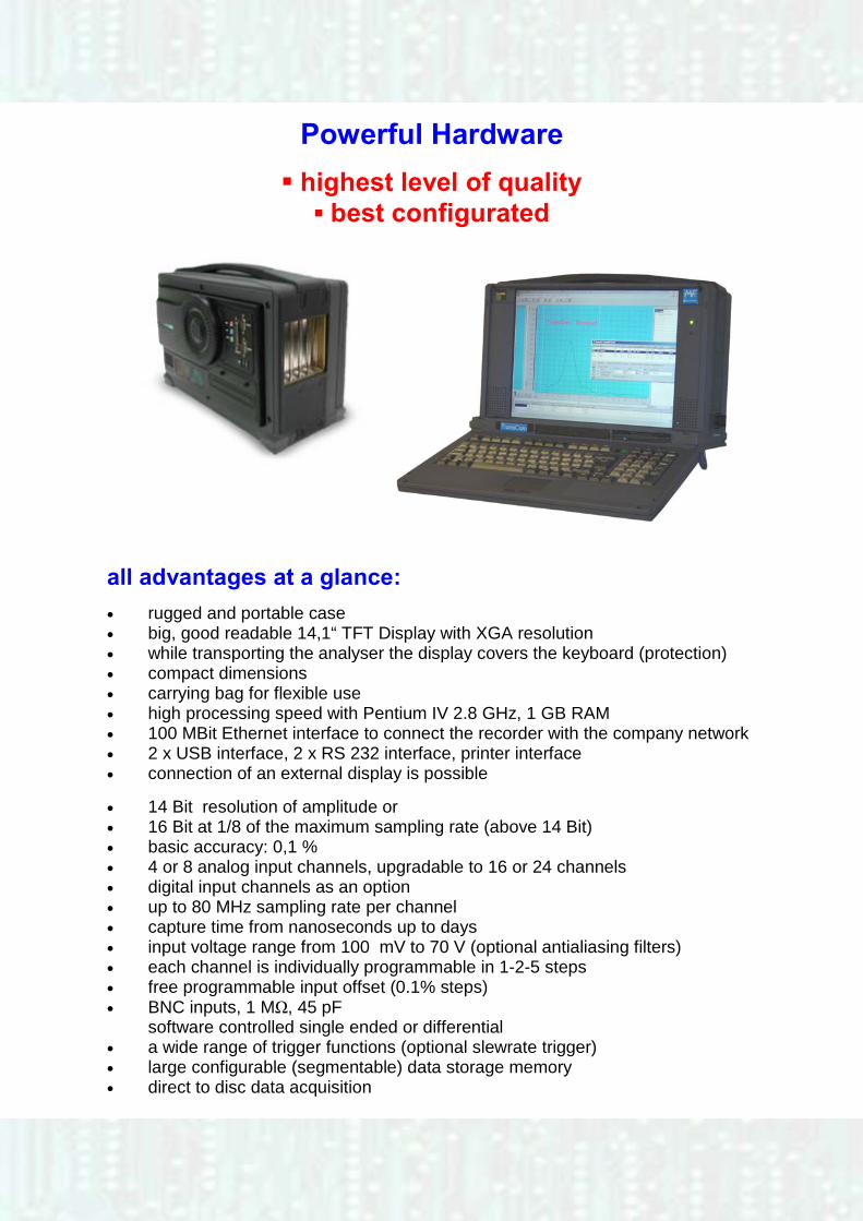
Powerful Hardware
highest level of quality best configurated
all advantages at a glance: • rugged and portable case • big, good readable 14,1“ TFT Display with XGA resolution • while transporting the analyser the display covers the keyboard (protection) • compact dimensions • carrying bag for flexible use • high processing speed with Pentium IV 2.8 GHz, 1 GB RAM • 100 MBit Ethernet interface to connect the recorder with the company network • 2 x USB interface, 2 x RS 232 interface, printer interface • connection of an external display is possible • 14 Bit resolution of amplitude or • 16 Bit at 1/8 of the maximum sampling rate (above 14 Bit) • basic accuracy: 0,1 % • 4 or 8 analog input channels, upgradable to 16 or 24 channels • digital input channels as an option • up to 80 MHz sampling rate per channel • capture time from nanoseconds up to days • input voltage range from 100 mV to 70 V (optional antialiasing filters) • each channel is individually programmable in 1-2-5 steps • free programmable input offset (0.1% steps) • BNC inputs, 1 MΩ, 45 pF software controlled single ended or differential • a wide range of trigger functions (optional slewrate trigger) • large configurable (segmentable) data storage memory • direct to disc data acquisition
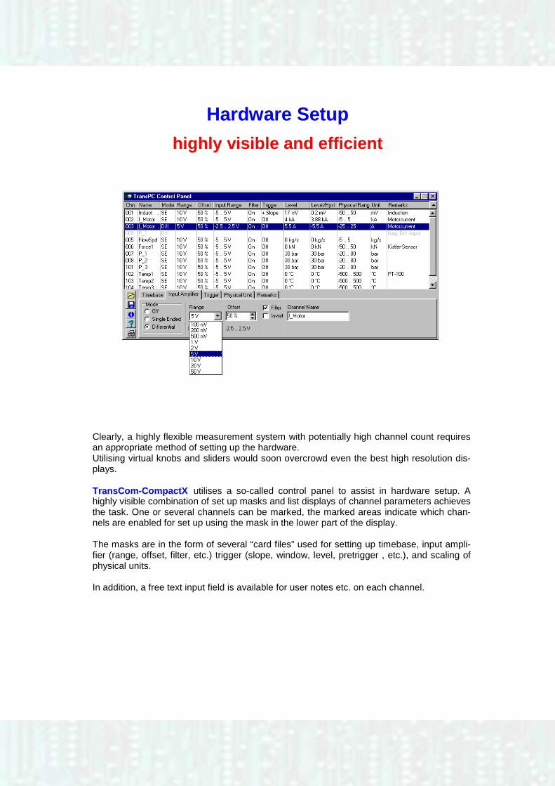
Hardware Setup
highly visible and efficient
Clearly, a highly flexible measurement system with potentially high channel count requires an appropriate method of setting up the hardware. Utilising virtual knobs and sliders would soon overcrowd even the best high resolution dis-plays. TransCom-CompactX utilises a so-called control panel to assist in hardware setup. A highly visible combination of set up masks and list displays of channel parameters achieves the task. One or several channels can be marked, the marked areas indicate which chan-nels are enabled for set up using the mask in the lower part of the display. The masks are in the form of several “card files” used for setting up timebase, input ampli-fier (range, offset, filter, etc.) trigger (slope, window, level, pretrigger , etc.), and scaling of physical units. In addition, a free text input field is available for user notes etc. on each channel.
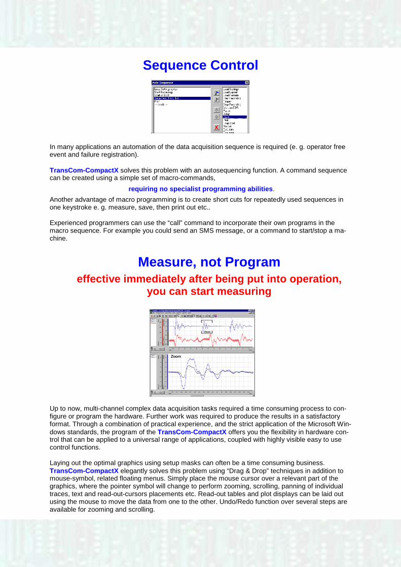
Sequence Control
In many applications an automation of the data acquisition sequence is required (e. g. operator free event and failure registration). TransCom-CompactX solves this problem with an autosequencing function. A command sequence can be created using a simple set of macro-commands,
requiring no specialist programming abilities.
Another advantage of macro programming is to create short cuts for repeatedly used sequences in one keystroke e. g. measure, save, then print out etc.. Experienced programmers can use the “call” command to incorporate their own programs in the macro sequence. For example you could send an SMS message, or a command to start/stop a ma-chine.
Measure, not Program
effective immediately after being put into operation, you can start measuring
Up to now, multi-channel complex data acquisition tasks required a time consuming process to con-figure or program the hardware. Further work was required to produce the results in a satisfactory format. Through a combination of practical experience, and the strict application of the Microsoft Win-dows standards, the program of the TransCom-CompactX offers you the flexibility in hardware con-trol that can be applied to a universal range of applications, coupled with highly visible easy to use control functions. Laying out the optimal graphics using setup masks can often be a time consuming business. TransCom-CompactX elegantly solves this problem using “Drag & Drop” techniques in addition to mouse-symbol, related floating menus. Simply place the mouse cursor over a relevant part of the graphics, where the pointer symbol will change to perform zooming, scrolling, panning of individual traces, text and read-out-cursors placements etc. Read-out tables and plot displays can be laid out using the mouse to move the data from one to the other. Undo/Redo function over several steps are available for zooming and scrolling.
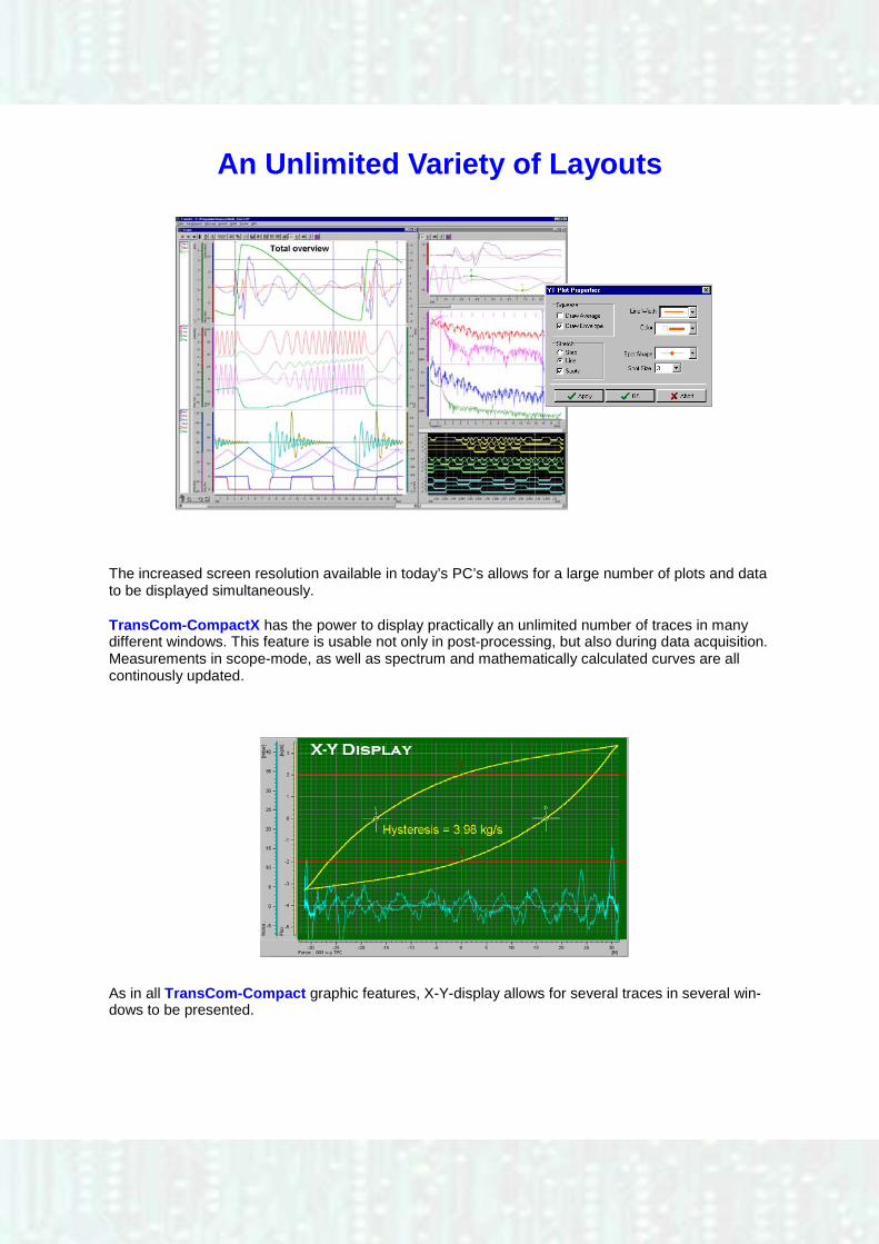
An Unlimited Variety of Layouts
The increased screen resolution available in today’s PC’s allows for a large number of plots and data to be displayed simultaneously. TransCom-CompactX has the power to display practically an unlimited number of traces in many different windows. This feature is usable not only in post-processing, but also during data acquisition. Measurements in scope-mode, as well as spectrum and mathematically calculated curves are all continously updated.
As in all TransCom-Compact graphic features, X-Y-display allows for several traces in several win-dows to be presented.
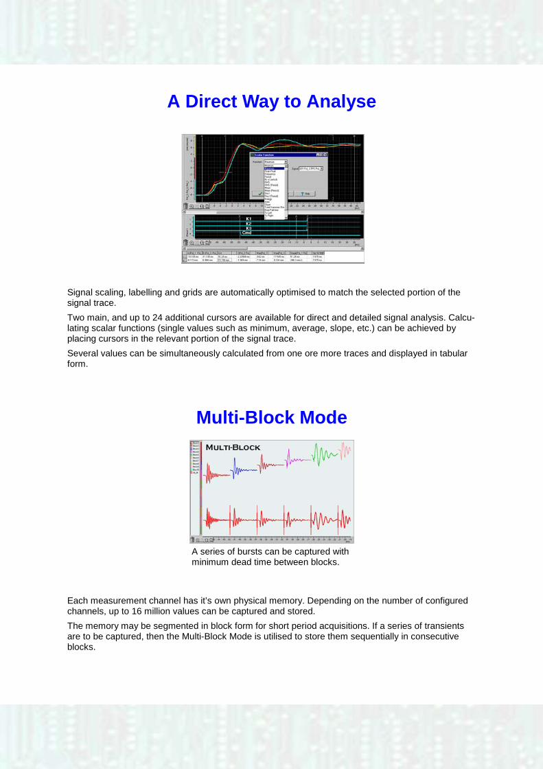
A Direct Way to Analyse
Signal scaling, labelling and grids are automatically optimised to match the selected portion of the signal trace.
Two main, and up to 24 additional cursors are available for direct and detailed signal analysis. Calcu-lating scalar functions (single values such as minimum, average, slope, etc.) can be achieved by placing cursors in the relevant portion of the signal trace.
Several values can be simultaneously calculated from one ore more traces and displayed in tabular form.
Each measurement channel has it’s own physical memory. Depending on the number of configured channels, up to 16 million values can be captured and stored.
The memory may be segmented in block form for short period acquisitions. If a series of transients are to be captured, then the Multi-Block Mode is utilised to store them sequentially in consecutive blocks.
Multi-Block Mode
A series of bursts can be captured with minimum dead time between blocks.

Synchronized Time Averaging
Averaging a signal over several triggered captures increases the signal to noise ratio making the desired signal more apparent.
A formula editor is available that makes trace calculations easy. Defined functions can be initiated in manual or automatic mode.
Curve Calculation?
Write a Formula
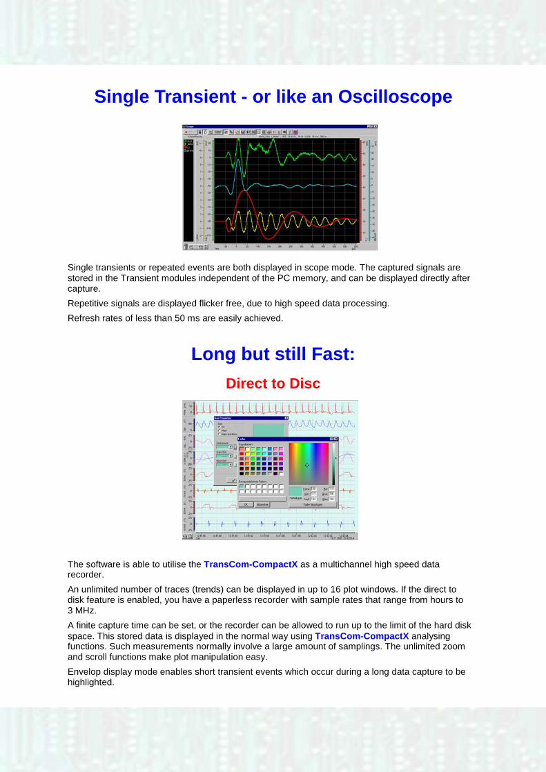
Single Transient - or like an Oscilloscope
Single transients or repeated events are both displayed in scope mode. The captured signals are stored in the Transient modules independent of the PC memory, and can be displayed directly after capture.
Repetitive signals are displayed flicker free, due to high speed data processing.
Refresh rates of less than 50 ms are easily achieved.
Long but still Fast:
Direct to Disc
The software is able to utilise the TransCom-CompactX as a multichannel high speed data recorder.
An unlimited number of traces (trends) can be displayed in up to 16 plot windows. If the direct to disk feature is enabled, you have a paperless recorder with sample rates that range from hours to 3 MHz.
A finite capture time can be set, or the recorder can be allowed to run up to the limit of the hard disk space. This stored data is displayed in the normal way using TransCom-CompactX analysing functions. Such measurements normally involve a large amount of samplings. The unlimited zoom and scroll functions make plot manipulation easy.
Envelop display mode enables short transient events which occur during a long data capture to be highlighted.
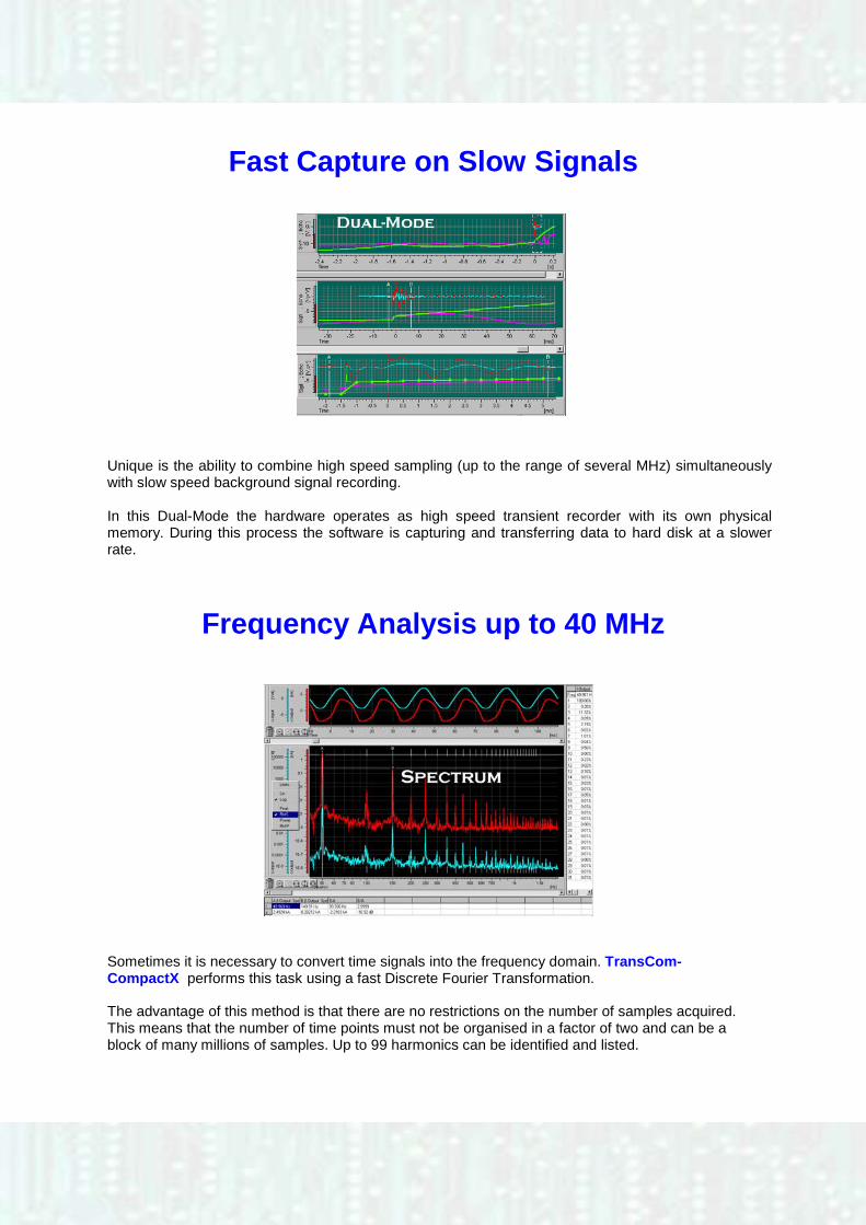
Fast Capture on Slow Signals
Unique is the ability to combine high speed sampling (up to the range of several MHz) simultaneously with slow speed background signal recording. In this Dual-Mode the hardware operates as high speed transient recorder with its own physical memory. During this process the software is capturing and transferring data to hard disk at a slower rate.
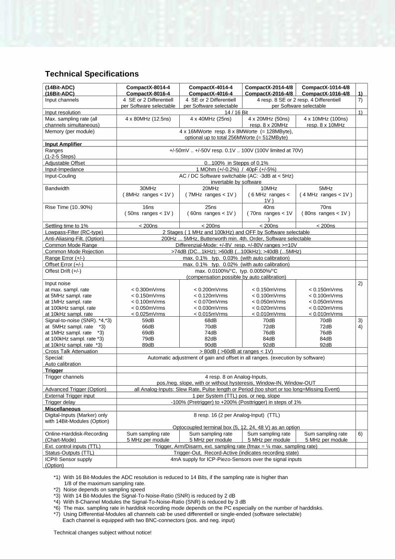
Frequency Analysis up to 40 MHz
Sometimes it is necessary to convert time signals into the frequency domain. TransCom-CompactX performs this task using a fast Discrete Fourier Transformation. The advantage of this method is that there are no restrictions on the number of samples acquired. This means that the number of time points must not be organised in a factor of two and can be a block of many millions of samples. Up to 99 harmonics can be identified and listed.
Technical Specifications (14Bit-ADC) (16Bit-ADC)
CompactX-8014-4 CompactX-8016-4
CompactX-4014-4 CompactX-4016-4
CompactX-2014-4/8 CompactX-2016-4/8
CompactX-1014-4/8 CompactX-1016-4/8
1)
Input channels 4 SE or 2 Differentiell per Software selectable
4 SE or 2 Differentiell per Software selectable
4 resp. 8 SE or 2 resp. 4 Differentiell per Software selectable
7)
Input resolution 14 / 16 Bit 1) Max. sampling rate (all channels simultaneous)
4 x 80MHz (12.5ns) 4 x 40MHz (25ns) 4 x 20MHz (50ns) resp. 8 x 20MHz
4 x 10MHz (100ns) resp. 8 x 10MHz
Memory (per module)
4 x 16MWorte resp. 8 x 8MWorte (= 128MByte), optional up to total 256MWorte (= 512MByte)
Input Amplifier Ranges (1-2-5 Steps)
+/-50mV .. +/-50V resp. 0.1V .. 100V (100V limited at 70V)
Adjustable Offset 0...100% in Stepps of 0.1% Input-Impedance 1 MOhm (+/-0.2%) / 40pF (+/-5%) Input-Couling AC / DC Software switchable (AC: -3dB at < 5Hz)
invertable by software
Bandwidth 30MHz ( 8MHz ranges < 1V )
20MHz ( 7MHz ranges < 1V )
10MHz ( 6 MHz ranges <
1V )
5MHz ( 4 MHz ranges < 1V )
Rise Time (10..90%) 16ns ( 50ns ranges < 1V )
25ns ( 60ns ranges < 1V )
40ns ( 70ns ranges < 1V
)
70ns ( 80ns ranges < 1V )
Settling time to 1% < 200ns < 200ns < 200ns < 200ns Lowpass-Filter (RC-type) 2 Stages ( 1 MHz and 100kHz) and OFF by Software selectable Anti-Aliasing-Filt. (Option) 200Hz ... 5MHz, Butterworth min. 4th. Order, Software selectable Common Mode Range Differenzial-Mode: +/-8V resp. +/-80V ranges >=10V Common Mode Rejection >74dB (DC...1kHz); >60dB (...100kHz); >40dB (...5MHz) Range Error (+/-) max. 0.1% typ. 0.03% (with auto calibration) Offset Error (+/-) max. 0.1% typ. 0.02% (with auto calibration) Offest Drift (+/-) max. 0.0100%/°C, typ. 0.0050%/°C
(compensation possible by auto calibration)
Input noise at max. sampl. rate at 5MHz sampl. rate at 1MHz sampl. rate at 100kHz sampl. rate at 10kHz sampl. rate
< 0.300mVrms < 0.150mVrms < 0.100mVrms < 0.050mVrms < 0.025mVrms
< 0.200mVrms < 0.120mVrms < 0.070mVrms < 0.030mVrms < 0.015mVrms
< 0.150mVrms < 0.100mVrms < 0.050mVrms < 0.020mVrms < 0.010mVrms
< 0.150mVrms < 0.100mVrms < 0.050mVrms < 0.020mVrms < 0.010mVrms
2)
Signal-to-noise (SNR). *4,*3) at 5MHz sampl. rate *3) at 1MHz sampl. rate *3) at 100kHz sampl. rate *3) at 10kHz sampl. rate *3)
59dB 66dB 69dB 79dB 89dB
68dB 70dB 74dB 82dB 90dB
70dB 72dB 76dB 84dB 92dB
70dB 72dB 76dB 84dB 92dB
3) 4)
Cross Talk Attenuation > 80dB ( >60dB at ranges < 1V) Special: Auto calibration
Automatic adjustment of gain and offset in all ranges. (execution by software)
Trigger Trigger channels
4 resp. 8 on Analog-Inputs, pos./neg. slope, with or without hysteresis, Window-IN, Window-OUT
Advanced Trigger (Option) all Analog-Inputs: Slew Rate, Pulse length or Period (too short or too long=Missing Event) External Trigger input 1 per System (TTL) pos. or neg. slope Trigger delay -100% (Pretrigger) to +200% (Posttrigger) in steps of 1% Miscellaneous Digital-Inputs (Marker) only with 14Bit-Modules (Option)
8 resp. 16 (2 per Analog-Input) (TTL)
Optocoupled terminal box (5, 12, 24, 48 V) as an option
Online-Harddisk-Recording (Chart-Mode)
Sum sampling rate 5 MHz per module
Sum sampling rate 5 MHz per module
Sum sampling rate 5 MHz per module
Sum sampling rate 5 MHz per module
6)
Ext. control inputs (TTL) Trigger, Arm/Disarm, ext. sampling rate (fmax = ¼ max. sampling rate) Status-Outputs (TTL) Trigger-Out, Record-Active (indicates recording state) ICP® Sensor supply (Option)
4mA supply for ICP-Piezo-Sensors over the signal inputs
*1) With 16 Bit-Modules the ADC resolution is reduced to 14 Bits, if the sampling rate is higher than 1/8 of the maximum sampling rate. *2) Noise depends on sampling speed *3) With 14 Bit-Modules the Signal-To-Noise-Ratio (SNR) is reduced by 2 dB *4) With 8-Channel Modules the Signal-To-Noise-Ratio (SNR) is reduced by 3 dB *6) The max. sampling rate in harddisk recording mode depends on the PC especially on the number of harddisks. *7) Using Differential-Modules all channels cab be used differentiell or single-ended (software selectable) Each channel is equipped with two BNC-connectors (pos. and neg. input) Technical changes subject without notice!
Part 2 of Technical Specifications
MF Instruments GmbH
Kranichstr. 6 D-72336 Balingen Tel.: ++49(0)7433/9898-0 Fax: ++49(0)7433/9898-70
E-Mail: [email protected] Internet: www.mf-instruments.de
With pleasure we also offer you Transient Recorders - up to 64 channels in a 19“ rack case - up to 100 MHz per channel - with fiber optical isolation - up to 96 channels integrated in one system - several systems to combine with consideration to your special wishes
PC System Display 14,1” TFT, XGA (1024 x 768) Processor Pentium IV, 2.8 GHz Memory 1 GB Harddisk 80 GB Drives DVD/CD-RW, Floppy Interfaces 2 x RS232, 2 x USB 2.0, Ethernet, Printer, Monitor Operating system Windows XP Professionell Housing Type „Shell in a Shell“ housing technology incl. carrying bag Dimensions W x H x D 40.01 x 28.58 x 19.79 cm Weight Ca. 9.5 Kg Environmental Power 100V – 240 V AC +/-5% / 47 – 63Hz and 400 Hz Temperature Operating: 0°C – 45°C
Non-operating: -10°C – 70°C Humidity Up to 85% non condensating Shock 10g 11ms ½ sine Vibration (IEC 68-2-6) 3 – 500Hz 0.41g All specifications subject to change without notice!