Embed Size (px)
Citation preview

Measurement and Estimation of the EquivalentCircuit Parameters for Multi-MW Battery Systems
Oluwaseun M. Akeyo1, Vandana Rallabandi1∗, Nicholas Jewell2, and Dan M. Ionel1
1SPARK Lab, ECE Department, University of Kentucky, Lexington, KY, [email protected], [email protected], [email protected]
2Louisville Gas and Electric and Kentucky Utilities, Louisville, KY, [email protected]
Abstract—This paper proposes and validates through sim-ulations and measurements, a procedure for the determiningthe equivalent circuit parameters of large utility-scale batteries.It is considered that a large battery includes multiple cellsconnected in series and parallel, and therefore, its equivalentcircuit can be represented as a series-parallel network of stateof charge (SOC) dependent resistors and capacitors. Tests fordetermining these equivalent circuit parameters are proposed.These tests involve subjecting the battery energy storage system(BESS) to multiple charge and discharge cycles, while monitoringthe terminal voltage and current response. A method for post-processing and analyzing the measurements in order to obtain anequivalent circuit model that accounts for the dynamic propertiesof the battery system and differences between the parameters ofeach cell is developed. The measurements and simulations areconducted for a 1MW/2MWh BESS demonstrator located at theLouisville Gas and Electric and Kentucky Utilities (LG&E andKU) E.W. Brown generating plant.
Index Terms—PV, battery, MPPT, grid connected inverter, dc-dc converter, charge controller, energy storage.
I. INTRODUCTION
According to the U.S. Energy Information Administration(EIA), as of the end of 2017, in excess of 700MW powerand 850MWh energy capacity utility-scale battery energystorage systems are in operation in the U.S. [1]. A substantialpercentage of the multi-MW battery systems are deployedfor renewable energy sources support, while also performingmultiple ancillary functions such as energy arbitrage, demandresponse, frequency response, power smoothing, and improv-ing system stability.
Recent studies have focused on the small-scale batterymodeling with greater emphasis on single cell operations[2]–[4]. Other researchers have worked towards developingstandardized procedures for the estimation of the parametersof a single cell. [5]–[8]. The ability to develop an equivalentcircuit model for utility-scale battery systems is becomingincreasingly critical due to the growing number of Multi-MW battery energy storage system (BESS) installations. Themodeling of batteries can facilitate the effective planning and
∗ Dr. Vandana Rallabandi was with the SPARK Laboratory, ECE Depart-ment, University of Kentucky, Lexington, KY and is now with GE Research,Niskayuna, NY.
scheduling of utility-scale BESS and help identify irregularbattery operations.
The conventional method for characterizing large scalebattery systems relies on the estimated parameters for one ofits cells, which are scaled to represent the behavior of theentire unit [9], [10]. The limitation of this approach is that thechemical variations between the cells within the system andthe effects of interconnecting multiple cells are ignored. In thisregard, this paper proposes tests to be conducted as well asmethods for developing an equivalent circuit model for utility-scale battery systems from the test data. The newly proposedprocedure accounts, which is based on tests performed on alarge BESS, therefore accounts for the behavior of each cellwithin the battery. The proposed procedure for parameter esti-mation benefits from measurements of the type recommendedby the new EPRI energy test manual [11], and may also serveas an extension to the EPRI initiative.
The simplified tests and measurements proposed in thispaper rely on using equipment typically present in utility-scaleBESS installations. In this approach, the BESS is subjectedto defined charge/discharge cycles and the dc terminal voltageresponse is measured, based upon which the parameters of theunit corresponding to specified SOC levels are determined. Aruntime equivalent battery system model is then developed andvalidated over three cases with experimental results retrievedfrom measurements conducted on a 1MW/2MWh BESS lo-cated at the LG&E and KU E.W. Brown generating plant.
II. EXPERIMENTAL FACILITIES
A typical standalone utility-scale BESS includes a batteryrack system with multiple cells connected to the dc-link of abidirectional dc to ac power conversion system (PCS) and atransformer for voltage matching, electrical isolation and gridinterconnection. The E.W. Brown facility battery demonstratorincludes a 2MWh battery system, a 1MVA bidirectional PCS, a13.2kV/480V step-up transformer and a 1MVA programmableload bank (Fig. 1). Voltage, current and power measurementsat the dc-link, inverter ac terminal, and the point of commoncoupling are synchronized with the local time and logged atone second intervals by the SCADA system.
Authors’ manuscript accepted for publication. The final published version is copyrighted by IEEE and available as: O. M. Akeyo, V. Rallabandi, N. Jewell and D. M. Ionel,”Measurement and Estimation of the Equivalent Circuit Parameters for Multi-MW Battery Systems,” 2019 IEEE Energy Conversion Congress and Exposition (ECCE), Baltimore,MD, USA, 2019, pp. 2499-2504, doi: 10.1109/ECCE.2019.8912233. ©2019 IEEE Copyright Notice. “Personal use of this material is permitted. Permission from IEEE must beobtained for all other uses, in any current or future media, including reprinting/republishing this material for advertising or promotional purposes, creating new collective works, forresale or redistribution to servers or lists, or reuse of any copyrighted component of this work in other works.”
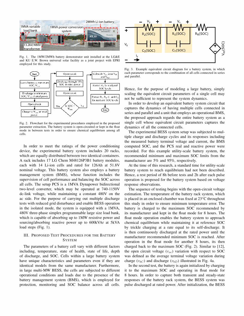
Fig. 1. The 1MW/2MWh battery demonstrator unit installed at the LG&Eand KU E.W. Brown universal solar facility as a joint project with EPRIemployed for this study.
Fig. 2. Flowchart for the experimental procedures employed in the proposedparameter extraction. The battery system is open-circuited or kept in the floatmode in between tests in order to ensure chemical equilibrium among allcells.
In order to meet the ratings of the power conditioningdevice, the experimental battery system includes 20 racks,which are equally distributed between two identical containers.A rack includes 17 LG Chem M48126P3B1 battery modules,each with 14 Li-ion cells and rated for 126Ah at 51.8Vnominal voltage. This battery system also employs a batterymanagement system (BMS), whose function includes thesupervision of cell performance and balancing the SOC acrossall cells. The setup PCS is a 1MVA Dynapower bidirectionaltwo-level converter, which may be operated at 740-1150Vdc-link voltage, while maintaining a constant 480V on theac side. For the purpose of carrying out multiple dischargetests with reduced grid disturbance and enable BESS operationin the isolated mode, the system is equipped with a 1MVA,480V three-phase simplex programmable large size load bank,which is capable of absorbing up to 1MW resistive power andsourcing/absorbing reactive power up to 600kVAr at 5kVAload steps (Fig. 1).
III. PROPOSED TEST PROCEDURES FOR THE BATTERYSYSTEM
The parameters of a battery cell vary with different factorsincluding, temperature, state of health, state of life, depthof discharge, and SOC. Cells within a large battery systemhave unique characteristics and parameters even if they areidentical models from the same manufacturer. Furthermore,in large multi-MW BESS, the cells are subjected to differentoperational conditions and loads due to the presence of thebattery management system (BMS), which is employed forprotection, monitoring and SOC balance across all cells.
Fig. 3. Example equivalent circuit diagram for a battery system, in whicheach parameter corresponds to the combination of all cells connected in seriesand parallel.
Hence, for the purpose of modeling a large battery, simplyscaling the equivalent circuit parameters of a single cell maynot be sufficient to represent the system dynamics.
In order to develop an equivalent battery system circuit thatcaptures the dynamics of having multiple cells connected inseries and parallel and a unit that employs an operational BMS,the proposed approach regards the entire battery system as asingle cell whose equivalent circuit parameters captures thedynamics of all the connected cells.
The experimental BESS system setup was subjected to mul-tiple charge and discharge cycles and its responses includingthe measured battery terminal voltage and current, the BMScomputed SOC, and the PCS real and reactive power wererecorded. For this example utility-scale battery system, therecommended minimum and maximum SOC limits from themanufacturer are 5% and 95%, respectively.
At the time of this research, a standard time for utility-scalebattery system to reach equilibrium had not been described.Hence, a rest period of 8h before tests and 2h after each pulseoperation is proposed for the battery system based on voltageresponse observations.
The sequence of testing begins with the open-circuit voltageestimation. The temperature of the battery rack system, whichis placed in an enclosed chamber was fixed at 23oC throughoutthis study in order to ensure minimum temperature error. Thebattery is charged to the maximum SOC recommended byits manufacturer and kept in the float mode for 8 hours. Thefloat mode operation enables the battery system to approachchemical equilibrium while maintaining it at reference SOCby trickle charging at a rate equal to its self-discharge. Itis then continuously discharged at the rated power until themanufacturer recommended minimum SOC is reached. Afteroperation in the float mode for another 8 hours, its thencharged back to the maximum SOC (Fig. 2). Similar to [12],the open circuit voltage (voc) variation with respect to SOCwas defined as the average terminal voltage variation duringcharge (vbC) and discharge (vbD) illustrated in Fig. 4a.
In the second test, the battery is again initialized by chargingit to the maximum SOC and operating in float mode for8 hours. In order to capture both transient and steady-stateresponses of the battery rack system, the BESS system waspulse discharged at rated power. After initialization, the BESS

(a) (b) (c)
(d) (e) (f)
Fig. 4. Battery system equivalent circuit parameters. The battery terminal voltage and SOC relationship during continuous charge and discharge is interpolatedto estimate its open-circuit voltage, while the series resistance and RC branch components are estimated through analysis of the terminal voltage during pulsedischarge. Open circuit voltage (a), series resistance (b), transient resistance 1 (c), transient capacitance 1 (d), transient resistance 2 (e), transient capacitance2 (f).
was continuously discharged at rated power through 10%SOC and operated in the float mode for 2 hours in order toallow the battery system to approach equilibrium. The 10%pulse discharge procedure was repeated until the system SOCreached the minimum. Conventional approaches require pulsedischarging the battery cell at constant current. The proposedprocedure is adapted to the equipment typically available ata utility scale BESS, and therefore, the PCS is controlled forpulse discharging the battery based on a power command.
IV. EXTRACTION OF EQUIVALENT CIRCUIT PARAMETERSFOR THE BATTERY SYSTEM
In this approach, the battery system is described as acontrollable voltage source connected in series to a resistance(R0) and multiple RC branches (R1, R2, C1 and C2), whereeach parameter represents all the connected cells (Fig. 3).For simplicity, variables such as number of charges cyclesand battery state of health are not considered. Hence, theparameters are only represented as a function of SOC. Thebattery system terminal voltage, vb during discharge may bedescribed as:
vb(t) = voc − ib R0 − v1(t)− v2(t), (1)
where, voc, is the battery open-circuit voltage; ib, the batterydc output current; v1 and v2 , the voltages across the RCbranches 1 and 2, respectively and t, the discharge duration.During the rated power continuous charge and discharge tests,the RC branches capacitors, C1 and C2 become fully charged
and thus, the battery system terminal voltage may be expressedas:
vbC , vbD ⇒ voc ± ib(R0 + R1 + R2), (2)
where, vbC are vbD are the measured terminal voltages duringcharge and discharge, respectively. Hence, voc as a functionof SOC was estimated as the average value of vbC and vbD atthe corresponding SOCs. Since the BESS was continuouslydispatched at the rated PCS power during these tests, themeasured ib increases as vb decreases due to reduction in SOC,leading to significant difference between vbC are vbD as theSOC approaches minimum (Fig. 4a).
The measurements during the pulse discharge were usedto estimate the value of the passive elements for the bat-tery system equivalent circuit. Based on the voltage-currentrelationship of a capacitor, during the battery system pulsedischarge, it was assumed that,
[v1(t−oc), v2(t−oc)] = [v1(t+oc), v2(t+oc)], (3)
where t−oc and t+oc are the times just before and after thebattery is open circuited for each pulse, respectively. Hence,the voltage transient after each pulse is exclusively credited toR0 and expressed as:
R0 =vb(t
−oc)− vb(t
+oc)
ib(t−oc)− ib(t
+oc)
. (4)
In this approach, the fairly logistic curve observed inthe measured voltage during open-circuit after each pulsedischarge was attributed to the exponential decay of the

(a) (b)
(c) (d)
Fig. 5. The equivalent battery system during rated power pulse discharge from maximum to minimum SOC showing: The experimental and simulated batterysystem terminal voltage variation (a), the percentage voltage error (b), the discharge current (c), and the SOC variation (d).
voltage across the capacitances. From (1) the capacitor voltageresponses after open-circuit may be expressed as:
v1(∆t) + v2(∆t) = voc − vb(∆t)− ib R0 (5)
where, ∆t, is the duration of open-circuit. Since the batteryself-discharge over 2h may be regarded insignificant in thisapplication, the battery system SOC was assumed to beconstant during the open-circuit period. The measured batteryvoltage from just before the open-circuit to the period when thevoltage starts to decay was isolated for each pulse discharge.This portion of the voltage curve is evaluated using (5), andthe combined RC branch voltage response may be written as
v1(∆t) + v2(∆t) = ib R1 e− ∆t
R1C1 + ib R2 e− ∆t
R2C2 . (6)
The measured RC branch voltage responses were fitted to(6) in other to estimate the RC parameters related to eachSOC. Single variable exponential functions were developedto establish the relationships between the equivalent circuitpassive elements and the battery system SOC (Fig. 4).
V. EXPERIMENTAL VALIDATION
The proposed battery system was validated over three BESScycles with all results presented at the resolution of one
second. The first test involves comparing the terminal voltageresponse of the equivalent circuit with experimental results,from which its parameters were developed. A maximum of0.6% voltage error calculated as a percentage of the experi-mental voltage was realized at approximately 55% SOC. Thiserror may be due to the battery system SOC variation whilethe PCS is connected in float mode. The peak voltage error isobserved during the connected load transient, and it may benoted that the battery system dc output current increases withreduction in its voltage in order to continue pulse dischargingat rated power as SOC diminishes (Fig. 5).
The equivalent battery system circuit was also validatedover continuous and diverse deep charge/discharge cycles.The BESS was subjected to one of the example test cyclesdescribed in the EPRI energy test manual, where it wasdischarged from maximum to 50% SOC, charged to maximumand then discharged to minimum SOC level at the rated power.This procedure was then repeated at 75% rated power and theresults show sufficient correlation between the experimentaland simulated voltage responses, demonstrating the accuracyof the battery system equivalent circuit over different initialSOC levels (Fig. 6).

(a) (b)
(c) (d)
Fig. 6. The battery system during dynamic charge and discharge between multiple SOC level at rated and 75% power showing the: Experimental and simulatedbattery system voltage variation (a), percentage voltage error (b), charge current (c), and SOC variation (d).
Battery energy storage systems may be employed for fre-quency response, where they are subjected to charge anddischarge operations in other to maintain the grid frequencyat its reference value. In this case, the experimental BESSwas operated in automatic frequency response mode withhigh sensitivity, to allow the BESS respond to frequencydeviations greater than 0.005Hz. The equivalent circuit modelwas connected to a current source whose output is identicalto the measured dc current. The accuracy of the equivalentbattery system was established based on the similarity betweenthe experimental and simulation voltage responses (Fig. 7).
VI. CONCLUSION
This paper proposes tests for determining the equivalentcircuit parameters of a multi-MW BESS. These tests rely onequipment already available at utility scale battery installa-tions. Furthermore, an approach to develop an active runtimeequivalent circuit model based on the tests is developed.Unlike other traditional methods, which involve scaling theparameters of a single cell, the proposed approach takesrealistically into account the chemical variations of the cells
within the battery system and the effects of interconnectingand balancing multiple cells.
The accuracy of the developed battery system equivalentcircuit was validated over three charge/discharge cycles, inwhich the simulated results were compared with experimentalmeasurements retrieved from a large scale experimental fa-cility, which includes a 1MW/2MWh BESS demonstrator and1MVA load. The results illustrate a voltage response with errorbelow 0.8%. The parameter estimation using optimizationtechniques as well as the establishment of a relationshipbetween the parameters of the constituent battery cells andthose of the unit are subjects of ongoing research.
ACKNOWLEDGMENT
The support of LG&E and KU, and University of Kentucky,the L. Stanley Pigman endowment, of the SPARK Laboratory,and the Power and Energy Institute of Kentucky (PEIK) isgratefully acknowledged.
REFERENCES
[1] U.S. Battery Storage Market Trends. U.S. Energy Information Admin-istration, May 2018.

(a) (b)
(c) (d)
Fig. 7. The battery system during automated grid frequency response, showing the: Experimental and simulated battery system terminal voltage variation (a),percentage voltage error (b), charge current (c) and SOC variation (d).
[2] D. Dvorak, T. Bauml, A. Holzinger, and H. Popp, “A comprehensivealgorithm for estimating lithium-ion battery parameters from measure-ments,” IEEE Transactions on Sustainable Energy, vol. 9, no. 2, pp.771–779, April 2018.
[3] C. R. Lashway and O. A. Mohammed, “Adaptive battery managementand parameter estimation through physics-based modeling and experi-mental verification,” IEEE Transactions on Transportation Electrifica-tion, vol. 2, no. 4, pp. 454–464, Dec 2016.
[4] H. M. Usman, S. Mukhopadhyay, and H. Rehman, “Universal adaptivestabilizer based optimization for li-ion battery model parameters estima-tion: An experimental study,” IEEE Access, vol. 6, pp. 49 546–49 562,2018.
[5] S. A. Hamidi, D. M. Ionel, and A. Nasiri, “Batteries and ultracapacitorsfor electric power systems with renewable energy sources,” RenewableEnergy Devices and Systems with Simulations in MATLAB® and AN-SYS®, 2017.
[6] A. Biswas, R. Gu, P. Kollmeyer, R. Ahmed, and A. Emadi, “Simulta-neous state and parameter estimation of li-ion battery with one statehysteresis model using augmented unscented kalman filter,” in 2018IEEE Transportation Electrification Conference and Expo (ITEC), June2018, pp. 1065–1070.
[7] D. C. Cambron and A. M. Cramer, “A lithium-ion battery current esti-mation technique using an unknown input observer,” IEEE Transactionson Vehicular Technology, vol. 66, no. 8, pp. 6707–6714, Aug 2017.
[8] A. M. Bizeray, J. Kim, S. R. Duncan, and D. A. Howey, “Identifiabilityand parameter estimation of the single particle lithium-ion batterymodel,” IEEE Transactions on Control Systems Technology, pp. 1–16,2018.
[9] X. Gong, R. Xiong, and C. C. Mi, “Study of the characteristics of batterypacks in electric vehicles with parallel-connected lithium-ion batterycells,” IEEE Transactions on Industry Applications, vol. 51, no. 2, pp.1872–1879, March 2015.
[10] J. Lee, J. Ahn, and B. K. Lee, “A novel li-ion battery pack modelingconsiderging single cell information and capacity variation,” in 2017IEEE Energy Conversion Congress and Exposition (ECCE), Oct 2017,pp. 5242–5247.
[11] Energy Storage Integration Council (ESIC) Energy Storage Test Manual.EPRI, Palo Alto, CA: 2017. 3002011739.
[12] H. He, R. Xiong, X. Zhang, F. Sun, and J. Fan, “State-of-chargeestimation of the lithium-ion battery using an adaptive extended kalmanfilter based on an improved thevenin model,” IEEE Transactions onVehicular Technology, vol. 60, no. 4, pp. 1461–1469, May 2011.


![Battery Model Parameter Estimation Using a Layered ... · A typical structure of an equivalent circuit model [1-2, 4-9] is shown in Figure 1. This circuit contains a voltage source](https://img.dokumen.tips/doc/110x75/5e6b7d4de052f6370f4e1b67/battery-model-parameter-estimation-using-a-layered-a-typical-structure-of-an.jpg)