Embed Size (px)
Citation preview

Measurement and Estimation of 3D Orientation using Magnetic and Inertial Sensors
Zunyi TANG,*, # Masaki SEKINE,* Toshiyo TAMURA,* Noriko TANAKA,* Masaki YOSHIDA,* Wenxi CHEN**
Abstract Magnetic and inertial sensors are becoming increasingly popular to measure three-dimensional (3D) orientation, because they are well suited to the ambulatory monitoring of posture and movements of subjects. This paper presents a complete implementation of the measurement and estimation of 3D orientation based on a magnetic and inertial measurement unit (MIMU) that we developed. The measurement unit was a combination of a 3D accelerometer, a 3D gyroscope, and a 3D mag-netometer. A Kalman �lter-based sensor fusion algorithm was proposed to implement the measurements and 3D orientation es-timates. The accuracy of the orientation estimation, calculated by a sensor fusion algorithm, was assessed by comparison with a laboratory-bound optical measurement system. Several simulation experiments were executed to evaluate the performance of the measurement unit under various states, including static, periodically rotational, arbitrarily dynamic, and vibration states. Exper-imental results showed accurate and drift-free orientation estimates. The averaged root-mean-square errors (RMSE) of the roll, pitch, and yaw Euler angles in static state were ≤0.6°. The averaged RMSE of the three angles in dynamic state or in dynamic tests at different angular velocities were ≤2.1°, regardless of periodic rotations and arbitrary motions.
Keywords: Kalman �lter, 3D orientation, inertial measurement unit, sensor fusion, magnetometer.
Adv Biomed Eng. 4: pp. 135–143, 2015.
1. Introduction
Three-dimensional (3D) measurements of the human body or body segments are important in clinical diagnoses, especially in the orthopedic and rehabilitation �elds. Although several systems and devices, such as optoelectronic systems (optical tracking sys-tems) and electromagnetic tracking systems, can take such mea-surements, there is a great need for an ambulatory system that can be used in and outside the laboratory setting or clinical environ-ment [1]. Recently, small wearable inertial/magnetic sensors have become increasingly popular for measurements of the 3D orientation of the human body or body segments, regardless of motion or static states [2]. Many researchers have proposed vari-ous systems based on accelerometers and gyroscopes (referred to as ‘inertial measurement units,’ IMUs) to measure the 3D orienta-tion of test objects [2–4]. Some researchers have integrated mag-netometers into IMUs to construct ‘magnetic and inertial mea-surement units’ (MIMU) [5] that provide higher degrees of freedom (DOF).
To measure 3D orientation, it is necessary to convert sensor data into information that represent 3D orientation, such as Euler angles or quaternions (in this paper, we describe measurements of 3D orientation in terms of the Euler angles). This conversion is also known as ‘sensor fusion,’ which is the combination of raw data from disparate sensors such as accelerometer, gyroscope and
magnetometer, such that the combined result is more accurate, more complete, and more dependable. This is why multiple sen-sors are used to measure 3D orientation together. Generally, the easy-to-use complementary �lter can perform the task of a sensor fusion, but is limited in performance [6, 7]. To obtain higher per-formance, the more competent Kalman �lter [2, 6, 8–11] is often used instead. In addition, quaternion-based and gradient de-scent-based methods have been developed for this task [12, 13, 19]. Other �ltering technologies, such as low-pass and high-pass �lters are also often used to remove noise or drift from sensor data. Noise often has serious effects on the outputs of low-cost gyroscopes, resulting in result drift over time. Magnetometers are also susceptible to interference from surrounding ferromagnetic materials [14]. This may also lead to severe drift and distortion in 3D measurements and estimations. Thus, before an IMU/MIMU can be applied to practical measurement of 3D orientation, it is necessary to reliably achieve sensor fusion, and to meticulously assess the accuracy of the measurements and estimates of 3D ori-entation.
In this paper, we use an MIMU that we previously developed as an example to systematically describe how to achieve 3D ori-entation estimates using an MIMU sensor.
2. System Design
In this section, we �rst describe the development of the 3D orien-tation measurement system. Next, a description of how to esti-mate 3D orientation using the proposed Kalman �lter-based sen-sor fusion algorithm is presented. Finally, by a series of experiments including static, rotational, and vibration tests, we assess the accuracy of estimates of 3D orientation using the MIMU by comparing to an optical measurement system as refer-ence. The root-mean-square error (RMSE) and correlation coef�-cient (CC) are used to evaluate differences and linear relationship between the estimates and the references, respectively.
Received on August 8, 2014; revised on December 18, 2014 and April 24, 2015; accepted on May 1, 2015.
* Faculty of Biomedical Engineering, Osaka Electro-Communica-tion University, Shijonawate, Osaka, Japan.
** School of Computer Science and Engineering, the University of Aizu, Aizuwakamatsu, Fukushima, Japan.
# 8–302, 1130–70 Kiyotaki, Shijonawate, Osaka 575–0063, Japan. E-mail: [email protected]
Original PaperAdvanced Biomedical Engineering4: 135–143, 2015.
DOI:10.14326/abe.4.135

2.1 MIMU Measurement SystemThe wearable MIMU measurement system that we developed consists of a sensor module and a PC-based control program. The sensor module primarily consists of a triaxial accelerometer (LSM303D, STMicroelectronics Corp., Switzerland), a triaxial gyroscope (L3GD20, STMicroelectronics Corp., Switzerland), a triaxial magnetometer (LSM303D, STMicroelectronics Corp., Switzerland), and a Bluetooth communication module. All sensor signals are sampled at 200 Hz at 14-bit resolution. Using the Bluetooth module, sensor data are sent to the PC control program that automatically calibrates the collected data and displays them functionally for further analysis. The PC control program was de-veloped using the Python programming language. Thus, it is a cross-platform application that can run on many OS platforms, including Windows and Linux. The appearance of the sensor module and the graphical user interface (GUI) of the control pro-gram are provided in Fig. 1.
2.2 Sensor Fusion using Adaptive Complementary Kalman Filter
A preliminary and important task for an MIMU sensor is to achieve sensor fusion for calculating the Euler angles consisting of three components: roll, pitch, and yaw, to describe the 3D ori-entation of a rigid body. Any orientation can be achieved by com-posing the three angle rotations. For an MIMU sensor, in fact, the Euler angles can be calculated using only gyroscope outputs, which provide integration of angular velocity over time. Howev-er, the computed results drift severely over time due to the effects of noise. Fortunately, this problem can be mitigated using com-plementary sensors along with sensor fusion schemes to obtain an optimal attitude estimate. Unlike gyroscopes, accelerometer and magnetometer outputs are generally stable and typically do not drift. They can be used as complementary sensors. Thus, the role of the gyroscope in the MIMU is to estimate the total roll, pitch, and yaw components of orientation. The role of the accelerometer is to compensate and correct the roll and pitch components ob-tained from the gyroscope. The role of the magnetometer is to compensate and correct the yaw component calculated from the gyroscope. Concretely speaking, measurement data from the ac-celerometer and magnetometer can be fused with the gyroscope output using a sensor fusion method, such as the Kalman �lter. In this work, the roll, pitch, and yaw were estimated using an adap-tive complementary Kalman �lter [15, 16] that tracks the state of the system, including the Euler angles, acceleration, angular ve-locity, and sensor biases. In the experiments described below, we compare the results of MIMU with and without the Kalman �lter in order to more clearly understand the role of the Kalman �lter in the sensor fusion algorithm.
The following equations show how to calculate the roll and pitch to estimate 3D orientation using only accelerometer out-puts:
αc = arctan
ay
a2x + a2
z
(1)
βc = arctan
ax
a2y + a2
z
(2)
where ax, ay, and az denote the accelerometer outputs for x, y, and z axes, respectively. Arctan( ) calculates the inverse tangent of an angle. αc and βc are used to compensate and correct the roll and pitch calculated from gyroscope output, respectively. As compen-sations, the two angles are inputs for the adaptive Kalman �lter (Fig. 2), described below, and fusion angles with gyroscope out-put can be calculated.
To compensate and correct the yaw, calculations require not only accelerometer output but also magnetometer output. The equation for calculating yaw from magnetometer output is as fol-lows [17]:
Hx = mx cos (β) + my sin (β) sin (α) + mz sin (β) cos (α)
Hy = my cos (α) − mz sin (α)
γc = arctanHy
Hx
(3)
where Hx and Hy represent the horizontal components of the earth’s magnetic �eld; mx, my, and mz denote the magnetometer output for x, y, and z axes, respectively; γc represents the yaw calculated from magnetometer output. Also, α and β represent the resulting roll and pitch, respectively, estimated with the adaptive Kalman �lter. Figure 2 shows a brief description of the sensor fusion algorithm for calculating the Euler angles.
The adaptive complementary Kalman �lter algorithm esti-mates the state of the system at time t, based on the prior state at time t − 1 [15, 16]. The algorithm involves two stages: prediction and measurement update. In the prediction stage, the anticipated state x∗
t, based on the linear mathematical model of the system, is represented as follows:
x∗t = Ftx̂t−1 + Btut (4)where x̂t is the state vector containing the current state (such as angle) of the system at time t; ut represents a control input; Ft is the state transition matrix, which applies the effect of each system state parameter at time t − 1 on the system state at time t; and Bt
Fig. 1 Appearance of the sensor module (left) and GUI of the control program (right).
Fig. 2 Structure of the proposed sensor fusion algorithm based on a complementary Kalman �lter.
Advanced Biomedical Engineering. Vol. 4, 2015.(136)

is the control input matrix, which applies the effects of each con-trol input parameter in the vector ut on the state vector. The cova-riance matrix Pt associated with the prediction x∗
t of an unknown true value xt is calculated as follows:
P∗t = FtPt−1FTt + Q (5)
where Q is the process noise covariance matrix associated with noisy control inputs. In the measurement update stage, the Kal-man �lter gain is computed at t as follows:
Kt = P∗t HT HP∗t HT + R−1
(6)
where H is the transformation matrix used to map state vector parameters into the measurement domain; and R is the uncertain-ty matrix associated with a noisy set of measurements. The esti-mate of the state is then calculated as a function of the model prediction, measurement, and Kalman gain:
x̂t = x∗t + Kt zt − Hx∗t (7)where zt is the measurement vector. The error covariance matrix P also needs to be corrected, based on the Kalman gain, as follows:
Pt = P∗t − KtHP∗t (8)The two processes of prediction and measurement update can be iterated traversing all t. The adaptive Kalman �lter we use as-sumes white Gaussian noise and a linear model of the system.
According to the analysis above, the adaptive Kalman-based sensor fusion algorithm and its parameters used in our experi-ments are summarized in the algorithm as follows:
Algorithm 1 Kalman-�lter-based sensor fusion.Require: sampling time Δt = 0.005 s, the state transition matrix
F = [1, Δt; 0, 1], initial state vector x̂0 = [0, 0]T, the control input matrix B = [Δt, 0]T, the control input vector u ∈ R1×r (gyroscope data for one axis), initial error covariance matrix P0 = [1, 0; 0, 1], the process noise covariance Q = [0.3, 0.3; 0.3, 0.3], the transformation matrix H = [1, 0], the uncertainty matrix R = [0.01, 0; 0, 0.03], the measurement vector z ∈ R1×r (the comple-mentary angle αc, βc, or γc).for t = 1 to r do
x∗t = Ftx̂t−1 + Btut
P∗t = FtPt−1FTt +Q
Kt = P∗t HT HP∗t HT + R−1
x̂t = x∗t +Kt zt −Hx∗tPt = P∗t −KtHP∗t
end forReturn the state vector x̂ containing the estimated angles
It is notable that the sampling time Δt was set as 0.005 s since the MIMU works at a sampling frequency of 200 Hz. The initial state vector x̂ , i.e., the estimated angle, is 0. The control input matrix B applies the effect of each gyroscope measurement in the vector u on the state vector. P is an error covariance matrix and is initially set an identity matrix of size 2. P is updated at ev-ery time step to determine how well the sensors are tracking the actual state. The process noise covariance matrix Q was deter-mined by repeating an experiment multiple times. R is the white Gaussian noise covariance matrix and was also tuned by repeat-ing an experiment multiple times. The measurement vector z is the complementary angle, αc, βc, or γc.
2.3 Optical Reference SystemThe 3D optical tracking system (OptiTrack FLEX: V100R2, Nat-uralPoint, USA) consists of six cameras operating at 100 Hz. This system was used as the reference measurement system in this study. The MIMU and reference system data were collected at different sampling frequencies; 200 Hz and 100 Hz, respectively. Thus, the data collected from the MIMU were sampled at inter-vals to facilitate comparison with the reference system. In addi-tion, the collected data was synchronized. The accuracy of the reference system was 0.1°.
2.4 Experimental MethodsThe purpose of the following experiments was to investigate the accuracy, stability, and reproducibility of the 3D orientation esti-mates under various conditions. A calibration procedure to obtain the gains and offsets of the accelerometer, gyroscope, and magne-tometer was performed to guarantee the accuracy of the Euler angles calculated. The magnetometer data were calibrated with an optimization algorithm so that raw data of an ellipsoid were con-verted into data in the form of a near-sphere [18]. In the experi-ments, all programs were coded in MATLAB, and were run with-in MATLAB 8.1 (R2013a) on a PC with a 1.7 GHz Intel Core i5 CPU and 4 G of memory.
To assess the accuracy of the 3D orientation estimation, we used the optical motion capture system as a reference. In most experiments, the surface of the test sensor had three re�ective markers attached to form a rigid combination. While sensor data were collected, the corresponding reference data from the optical motion capture system were obtained for comparison. The accu-racy and stability of the sensor were �rst investigated under static conditions. The sensor with markers attached was �xed on a gim-bal and was then rotated through various angles such as 60°, 90°, and 180°. The sensor was kept in a static state for several seconds between any two successive rotations. We assessed the accuracy of the 3D orientation of the sensor only under the static stage, not considering the dynamic stage. Under static state conditions, the RMSE of the estimated roll, pitch, and yaw of the sensor unit compared to the references were calculated. The static state ex-periment was repeated �ve times for each axis, and the average RMSE were calculated.
Next, we assessed the performance of the sensor under peri-odic rotation conditions. In this experiment, the sensor was rotat-ed continuously in the range of 180° around each axis to assess the accuracy of the estimated Euler angles. The sensor with three re�ective markers attached was �xed on a 1 DOF gimbal. The gimbal was able to rotate in a range of 180°. With adjustments, the gimbal was able to produce 3DOF rotations. Because the gimbal used here could not rotate through 360°, no rotation test for the complete 360° was performed. We investigated the performance of the sensor unit under conditions of rotational angular velocities 40°/s, 60°/s, and 90°/s. The averaged RMSE of the results for the three angular velocities compared to the references were calculat-ed. In addition, the closeness of the results compared to the refer-ence was assessed by calculating CC using the MATLAB corrco-ef function.
To assess the stability of the 3D orientation estimation, we used a vibration generator that can repeatedly provide reciprocat-ing motion to drive the sensor up and down around the direction parallel to one axis of the sensor, in order to evaluate whether
Zunyi TANG, et al: Measurement and Estimation of 3D Orientation (137)

abnormal output occurs. In the vibration experiment, the sensor with re�ective markers attached was rigidly connected to the vi-brator by a foam material measuring 120 cm × 10 cm × 10 cm in order to avoid magnetic interference between the vibrator and sensor. For the vibration test, a sinusoidal wave of frequency 10 Hz generated by a wave generator was input into the vibrator to output continuous vibration (up and down). During the experi-ment, the test sensor was not rotated, but a periodic external force (±1 g) from the vibration generator was applied to the sensor along only one axis, minimizing any effect on the two other axes. Obviously, the test sensor should not detect any change in the 3D orientation due to no rotation, although the position of the sensor was changing along the direction of the external force. Figure 3 shows the settings of the vibration experiment and the periodic rotation experiment. Under the conditions of vibration, the RMSE of the estimated roll, pitch, and yaw of the sensor unit compared to the references were calculated.
In addition to the experiments with regular and periodic mo-tions, we also performed an experiment with arbitrary motion, because this is also necessary for the evaluation. At the beginning of the experiment, the sensor with three markers attached was held statically by hand. Then, combined rotations at arbitrary an-gles around each axis were made. Finally, we performed a set of experiments on a young subject to investigate the applicability of the sensor to real-world situations. The subject had a sensor �xed on the front of the shin, and was instructed to execute two sets of lunge actions. The subject �rst stood statically for 10 s at the be-ginning of the experiment. Then, the subject made a regular lunge, holding the action for 6 s, and returned to the original standing state. After 10 s, the subject repeated the same action again. This study was approved by the Ethics Committee of our university and written informed consent was given by the subject prior to enrolment. For the experiments, the RMSE and CC of the estimated roll, pitch, and yaw of the sensor unit compared to the references were also calculated.
3. Results
In this section, the overall estimation performance is described by comparing with the reference results obtained from the optical motion capture system and the estimation results without the Kal-man �lter (integration of gyroscope measurements over time). The static state experiments showed no drift or interference prob-lems for 3D orientation estimates. As mentioned above, we only evaluated the accuracy of 3D orientation estimation for the static stage of the experiment. The averaged RMSE of roll, pitch, and yaw of the MIMU with Kalman �lter compared to the reference system were 0.5°, 0.5°, and 0.6°, respectively.
Typical trials of static state experiments for roll, pitch, and yaw are shown in Figs. 4, 5, and 6, respectively. Note that green lines denote the results of MIMU without Kalman �lter, i.e., the results were calculated using only gyroscope output. Obviously, these results without Kalman �lter drifted seriously.
Fig. 4 An intuitive comparison of roll in a static state experiment.
Fig. 5 An intuitive comparison of pitch in a static state experiment.
Fig. 6 An intuitive comparison of yaw in a static state experiment.
Fig. 3 The settings of the vibration experiment and the periodic rota-tion experiment.
Advanced Biomedical Engineering. Vol. 4, 2015.(138)

Results of the rotation experiments also showed high perfor-mance of the sensor unit. A typical example of the rotation exper-iments for roll is shown in Fig. 7, where the corresponding angu-lar velocities from top to bottom are approximately 40°/s, 60°/s, and 90°/s, respectively. The RMSE of the estimated roll compar-ing to the references for the respective angular velocities were
1.0°, 1.1°, and 1.2°. The RMSE were by no means large, and the estimates (MIMU with Kalman �lter) coincided well with the ref-erences even with increasing angular velocities. In addition, cor-relation coef�cient was used to assess the linear relationship be-tween the estimates and the references. For the data of Fig. 7, the CC between the estimates and the references was 1.00, indicating that they were very similar to each other. For pitch and yaw, the results similar to those for roll were obtained under the same con-ditions. Thus, the averaged RMSE of roll, pitch, and yaw of the MIMU with Kalman �lter compared to the reference system were 1.1°, 1.5°, and 2.1°, respectively, for rotations at different angular velocities. Finally, the results of the MIMU without Kalman �lter (greens lines in Fig. 7) also exhibited serious drifts.
For the vibration experiments, Fig. 8 shows some of the sen-sor data collected. In the �gure, gx, gy, and gz denote the angular velocity measurements around x, y, and z axes, respectively, of the gyroscope; ax, ay, and az are the acceleration outputs at the three axes of the accelerometer; and mx, my, and mz correspond to the 3-axis outputs of the magnetometer. These data indicate that the sensor was vibrating up and down because the accelerometer out-put showed a sine wave only along the axis parallel to gravity due to the changing external force from the vibration generator, while the outputs at the other axes were almost zero. To assess the per-formance of the sensor under conditions of vibration, it is neces-sary to �rst determine the performance of sensor in a static state. Under the conditions of complete static state, the RMSE of the estimated roll, pitch, and yaw compared to the references were 0.05°, 0.06°, and 0.1°, respectively. Under conditions of vibration, the RMSE of the estimated roll, pitch, and yaw were 0.4°, 0.4°, and 0.3°, respectively. Therefore, the RMSE did not become par-ticularly large in the vibration state. The differences between the
Fig. 7 Comparisons of the estimated roll in the rotation experiments with angular velocity of approximately 40°/s (a), 60°/s (b), and 90°/s (c).
Fig. 8 Presentation of some sensor data collected during a trial of the vibration experiment. (a) gyroscope outputs, (b) accelerometer outputs (c) magnetometer outputs, (d) differences in estimated roll, pitch, and yaw between the MIMU with Kalman �lter and the reference system.
Zunyi TANG, et al: Measurement and Estimation of 3D Orientation (139)
estimates (the MIMU with Kalman �lter) and the references were mostly within the range of −1° to 1° (lowest �gure of Fig. 8).
Figure 9 shows a typical trial in the arbitrary motion exper-iment and the differences between the estimates and references for roll, pitch, and yaw. The RMSE of the estimated roll, pitch, and yaw were 1.0°, 1.2°, and 1.3°, respectively. The respective CC were 1.00, 0.99, and 0.99.
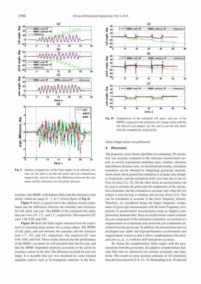
Figure 10 shows the Euler angles obtained from the experi-ment of executing lunge actions for a young subject. The RMSE of roll, pitch, and yaw between the estimates and the reference were 1.7°, 3.6°, and 4.8°, respectively. The respective CC were 0.94, 0.88, and 0.84. These results showed that the performance of the MIMU was better for roll and pitch than that for yaw, and that the MIMU responded relatively accurately to the action by wearing a sensor on the shin. The difference in result for yaw was larger. It is possible that yaw was interfered by some external magnetic sources such as ferromagnetic materials in the �oor,
when a lunge action was performed.
4. Discussion
The proposed sensor fusion algorithm for estimating 3D orienta-tion was accurate compared to the reference measurement sys-tem, in several experiments including static, rotation, vibration, and arbitrary dynamic tests. As mentioned previously, orientation estimation can be obtained by integrating gyroscope measure-ments alone, but in general the estimation is accurate only at high-er frequencies, and the estimation drifts over time due to the ef-fects of noise [12, 13]. On the other hand, an accelerometer can be used to estimate the pitch and roll components of the orienta-tion estimation, but the estimation is accurate only when the test subject is non-moving or rotating and moving slowly [12]. This can be considered as accurate in the lower frequency domain. Therefore, we considered fusing the higher frequency compo-nents of gyroscope measurements with the lower frequency com-ponents of accelerometer measurements using an adaptive com-plementary Kalman �lter. Since an accelerometer cannot estimate the yaw component of the orientation estimation, we resorted to a magnetometer to compensate and correct the yaw component cal-culated from the gyroscope. In addition, the measurement unit we developed uses stable and high-performance accelerometer and magnetometer sensors so that it offers complementary roll, pitch, and yaw (αc, βc, γc) with less drift and greater accuracy.
By fusing the complementary Euler angles with the mea-surements from the gyroscopes, the adaptive complementary Kal-man �lter that we optimized can estimate accurately and adap-tively. This results in more accurate estimates of 3D orientation than previous research [5, 8, 12, 14]. Roetenberg et al. [5] showed
Fig. 10 Comparisons of the estimated roll, pitch, and yaw of the MIMU compared to the references for a lunge action with the left shin of a test subject. (a), (b), and (c) are the roll, pitch, and yaw comparisons, respectively.
Fig. 9 Intuitive comparisons of the Euler angles in an arbitrary mo-tion. (a), (b), and (c) are the roll, pitch, and yaw comparisons, respectively, and (d) shows the differences between the esti-mates and the references for roll, pitch, and yaw.
Advanced Biomedical Engineering. Vol. 4, 2015.(140)

that the orientation error for the bench tests including slow move-ment and rotations along all axes was 3.0°. Roetenberg et al. [14] also claimed that under static and dynamic state conditions, the accuracy of their sensor was 1.4° and 2.6°, respectively. However, the accuracy of the sensor we developed was 0.6° in static states and 2.1° in dynamic states. Clearly, the performance of our sensor is superior. Madgwick et al. [19] proposed a sensor fusion algo-rithm using a gradient descent method and achieved orientation accuracy of less than 0.8° in static states and less than 1.7° in dy-namic states. Sabatini [12] claimed that the accuracy of the MIMU used in their study was less than 1° in static states and less than 3° in dynamic states. Our results are comparable to those results. Note that in the rotation experiment, only results for angu-lar velocities less than 90°/s were available because of the limita-tion of the simulation device. The gimbal used in the periodic rotation experiment generates mechanical disturbances when ro-tating at angular velocities faster than 90°/s, resulting in serious interference to the results of the sensor unit. On the other hand, the adaptive complementary Kalman �lter used assumes white Gaussian noise in the sensor data and a linear model of the sys-tem. As real-world practical issues, the noise may not really be white, the model of the system may tend to be non-linear in cer-tain states, and the �lter equations may be of a higher order. Thus, there are many possibilities to improve the performance of the proposed system.
For the vibration test, we expected to obtain near-zero out-puts at the three axes of the gyroscope. However, from the sensor data shown in Fig. 8, it can be seen that the gyroscope has slight non-zero outputs with time at the three axes, because it is dif�cult for the gyroscope to maintain almost zero outputs during vibra-tion due to the high sensitivity and internal noise. Despite the small outputs at the three axes of the gyroscope, the sensor did not detect rotation at all. The outputs of the magnetometer also con-�rmed this. These results also demonstrate that the outputs of the sensor and the estimates of 3D orientation are stable, and are not disturbed by the external force of the vibration.
Several studies have reported the effects of surrounding con-ductive and ferromagnetic materials on the accuracy of 3D mea-surements using magnetic sensors [8, 14]. In this study, the mea-surement unit was tested without ferromagnetic materials in the vicinity. If magnetic materials are close to the test sensor, the ef-fect on yaw results will be serious, similar to the result of yaw shown in Fig. 10, because the current sensor fusion algorithm does not consider compensation for interference with the magnet-ic �elds. This issue will be addressed in future work.
Compared to a similar-level product, the ‘MTx’ of Xsens Technologies, which was claimed to have a dynamic accuracy 1 of <2° depending on the type of motion [20], our MIMU appears to have a level of performance similar to the MTx.
5. Conclusions
In this paper, we present the complete implementation of a system for the measurement and estimation of 3D orientation based on a magnetic and inertial measurement unit (MIMU). We propose to
use a Kalman �lter-based sensor fusion algorithm to estimate 3D orientation. The accuracy of the 3D orientation estimates ob-tained from the sensor was assessed by comparing with the results obtained from an optical motion capture system. We evaluated the performance of the sensor in a series of experiments. The results showed that the averaged RMSE of roll, pitch, and yaw were ≤0.6° under static state conditions. Under dynamic conditions at angular velocities of 40°/s, 60°/s, and 90°/s, the averaged RMSE at the three angles were ≤2.1°, regardless of periodic rotations and arbitrary motions.
Con�ict of Interest
We have no con�icts of interest relationship with any companies or commercial organizations based on the de�nition of Japanese Society of Medical and Biological Engineering.
Acknowledgements
This work was supported in part by grants-in-aid from the Re-gional Innovation Strategy Support Program 2011–2015 and the grant-in-Aid for Scienti�c Research (C) 26350855, Ministry of Education, Culture, Sports, Science and Technology, Japan and by grants-in-aid from Strategic Information and Communications R&D Promotion Programme (SCOPE) 2014–2016, Ministry of Internal Affairs and Communication, Japan.
References
1. Giansanti D, Maccioni G, Macellari V: The development and test of a device for the reconstruction of 3-dposition and orientation by means of a kinematic sensor assembly with rate gyroscopes and accelerometers. IEEE Trans Biomed Eng. 52(7), pp. 1271–1277, 2005.
2. Fong DT, Chan YY: The use of wearable inertial motion sensors in human lower limb biomechanics studies: a systematic review. Sensors. 10(12), pp. 11556–11565, 2010.
3. Luinge HJ, Veltink PH: Measuring orientation of human body segments using miniature gyroscopes and accelerometers. Med Biol Eng Comput. 43(2), pp. 273–282, 2005.
4. Cooper G, Sheret I, McMillian L, Siliverdis K, Sha N, Hodgins D, Kenney L, Howard D: Inertial sensor based knee �exion/ex-tension angle estimation. J Biomech. 42(16), pp. 2678–2685, 2009.
5. Roetenberg D, Slycke P, Veltink P: Ambulatory position and ori-entation tracking fusing magnetic and inertial sensing. IEEE Trans Biomed Eng. 54(5), pp. 883–890, 2007.
6. Higgins W: A comparison of complementary and Kalman �lter-ing. IEEE Trans Aero Elec Sys. AES-11(3), pp. 321–325, 1975.
7. Euston M, Coote P, Mahony R, Kim J, Hamel T: A complemen-tary �lter for attitude estimation of a �xed-wing UAV. Proc of 2008 IEEE/RSJ International Conference on Intelligent Robots and Systems, pp. 340–345, 2008.
8. Roetenberg D, Baten CT, Veltink PH: Estimating body segment orientation by applying inertial and magnetic sensing near ferro-magnetic materials. IEEE Trans Neural Syst Rehabil Eng. 15(3), pp. 469–471, 2007.
9. Saito H, Watanabe T: Kalman-�ltering-based joint angle mea-surement with wireless wearable sensor system for simpli�ed gait analysis. IEICE T Inf and Syst. 94(8), pp. 1716–1720, 2011.
10. Shin EH, El-Sheimy N: An unscented Kalman �lter for in-mo-tion alignment of low-cost IMUs. Proc of 2004 IEEE Position Location and Navigation Symposium, pp. 273–279, 2004,
11. Won SH, Melek WW, Golnaraghi F: A Kalman/particle �l-
1 Dynamic accuracy is the measurement accuracy of the sensor sys-tem when it is being in dynamic condition or state and not exceed-ing the measurement range of the individual on-board sensors. It is generally measured with RMSE.
Zunyi TANG, et al: Measurement and Estimation of 3D Orientation (141)

ter-based position and orientation estimation method using a po-sition sensor/inertial measurement unit hybrid system. IEEE Trans Ind Electro. 57(5), pp. 1787–1798, 2010.
12. Sabatini AM: Quaternion-based extended Kalman �lter for deter-mining orientation by inertial and magnetic sensing. IEEE Trans Biomed Eng. 53(7), pp. 1346–1356, 2006.
13. Yun X, Bachmann ER: Design, implementation, and experimen-tal results of a quaternion-based Kalman �lter for human body motion tracking. IEEE Trans Robotic. 22(6), pp. 1216–1227, 2006.
14. Roetenberg D, Luinge HJ, Baten CT, Veltink PH: Compensation of magnetic disturbances improves inertial and magnetic sensing of human body segment orientation. IEEE Trans on Neural Syst Rehabil Eng. 13(3), pp. 395–405, 2005.
15. Welch G, Bishop G: An introduction to the Kalman �lter. 1995. 16. Faragher R: Understanding the basis of the Kalman �lter via a
simple and intuitive derivation. IEEE Signal Proc Mag. 29(5), pp. 128–132, 2012.
17. Caruso M: Applications of magnetic sensors for low cost com-pass systems. Proc of 2000 IEEE in Position Location and Navi-gation Symposium, pp. 177–184, 2000.
18. Merayo JM, Brauer P, Primdahl F, Petersen JR, Nielsen OV: Sca-lar calibration of vector magnetometers. Meas Sci Technol. 11(2), pp. 120–132, 2000.
19. Madgwick SOH, Harrison AJL, Vaidyanathan R: Estimation of IMU and MARG orientation using a gradient descent algorithm. Proc of 2011 IEEE International Conference on Rehabilitation Robotics, pp. 1–7, 2011.
20. MTi and MTx user manual and technical documentation. Xsens Technologies B.V., Oct. 2010.
Zunyi TANG
He received the M.S. and Ph.D. degrees in Com-
puter and Information Systems from the University
of Aizu, Japan, in 2009 and 2013, respectively.
Since 2013, he has been a Postdoctoral Fellow at
the Faculty of Biomedical Engineering, Osaka
Electro-Communication University, Japan. His re-
search interests include biosignal processing, blind signal processing,
sparse representation, machine learning and optimization.
Masaki SEKINE
He received Ph.D. degrees from Tokyo Denki Uni-
versity, Japan, in 1996, 1998 and 2001, respective-
ly. He was a postdoctoral fellow at the National
Institute for Longevity Sciences, Japan, in 2001.
From 2001 to 2003, he worked as a research asso-
ciate at Thayer School of Engineering, Dartmouth
College. From 2004 to 2011, he was an assistant professor at the De-
partment of Medical System Engineering, Chiba University, Japan. He
is currently a research associate professor at the Faculty of Biomedical
Engineering, Osaka Electro-Communication University and is in-
volved with Keihanna Development Region as an invitation researcher.
Toshiyo TAMURA
He received Ph.D. from Tokyo Medical and Dental
University in 1980. He is currently a Distinguished
Professor, School of Biomedical Engineering,
Osaka Electro-Communication University, Japan.
He also holds several adjunct positions in universi-
ties in Japan and Singapore. His research interests
include biomedical instrumentation, biosignal processing, telemedi-
cine telecare, home care technology and rehabilitation engineering. His
research has resulted in over 100 English reviewed articles. He has
served as a chair of IEEE/EMBS Tokyo Chapter in 1996–2000, and the
Asian Paci�c representative for the EMBS from 2000 to 2004. He was
a-president of Japanese Society of Medical Electronics and Biological
Engineering in 2010–2012 and a-president of Japanese Society of Life
Support Technology in 2009–2011.
Noriko TANAKA
She received Ph.D. degree from Nara Institute of
Science and Technology, Japan, in 2010. She is
currently the professor at the Department of Phys-
ical Therapy, in Faculty of Biomedical Engineer-
ing, Osaka Electro-Communication University.
Masaki YOSHIDA
He is professor of Faculty of Biomedical Engineer-
ing, Osaka Electro-communication University. He
received a B.S. in 1976, an M.S. in 1978 and Ph.D.
in 1995 all in Electrical Engineering from Osaka
University. Following a stint as Lecturer at School
of Allied Medical Sciences, Kobe University in
1984, he was appointed Associate Professor at the Faculty of Engineer-
ing, Kobe University. In 1998, he was appointed Professor at the Facul-
ty of Engineering, Osaka Electro-Communication University. He re-
ceived Japanese Society for Medical and Biological Engineering
Award in 1983. His current research interests are signal processing,
analyses of EMG signals and analysis of foot function. He is a member
of the Japan Society for Medical and Biological Engineering, the Soci-
ety of Instrument and Control Engineers and IEEE.
Advanced Biomedical Engineering. Vol. 4, 2015.(142)

Wenxi CHEN
He received Bachelor and Master degrees in Bio-
medical Engineering from Zhejiang University,
China in 1983 and 1986, respectively. He received
Ph.D. degree in biomedical instrumentation from
Institute of Biomaterials and Bioengineering, To-
kyo Medical and Dental University, Japan in 2001.
He is currently a professor in Biomedical Information Technology Lab
in the University of Aizu. He has participated more than 10 major R&D
projects funded by Japanese government ministries, Fukushima prefec-
ture and industries since 1998. These activities produced more than 30
patents (20 registered) and more than 160 papers. Some academic out-
comes have been commercialized or are in progress. His current re-
search interests focus on developing diversi�ed modalities to detect
physiological signal under daily life environment, and on performing
comprehensive interpretation of multifarious long-term data to reveal
statistical links and causalities among diseases as well as how they in-
teract with various factors in temporal/spatial domains.
Zunyi TANG, et al: Measurement and Estimation of 3D Orientation (143)