Embed Size (px)
Citation preview

Measure Guideline: Deep Energy Enclosure Retrofit for Interior Insulation of Masonry Walls S. Musunuru and B. Pettit Building Science Corporation April 2015

NOTICE
This report was prepared as an account of work sponsored by an agency of the United States government. Neither the United States government nor any agency thereof, nor any of their employees, subcontractors, or affiliated partners makes any warranty, express or implied, or assumes any legal liability or responsibility for the accuracy, completeness, or usefulness of any information, apparatus, product, or process disclosed, or represents that its use would not infringe privately owned rights. Reference herein to any specific commercial product, process, or service by trade name, trademark, manufacturer, or otherwise does not necessarily constitute or imply its endorsement, recommendation, or favoring by the United States government or any agency thereof. The views and opinions of authors expressed herein do not necessarily state or reflect those of the United States government or any agency thereof.
Available electronically at http://www.osti.gov/scitech
Available for a processing fee to U.S. Department of Energy and its contractors, in paper, from:
U.S. Department of Energy Office of Scientific and Technical Information P.O. Box 62 Oak Ridge, TN 37831-0062 phone: 865.576.8401 fax: 865.576.5728 email: mailto:[email protected]
Available for sale to the public, in paper, from: U.S. Department of Commerce National Technical Information Service 5285 Port Royal Road Springfield, VA 22161 phone: 800.553.6847 fax: 703.605.6900 email: [email protected] online ordering: http://www.ntis.gov/help/ordermethods.aspx
Measure Guideline: Deep Energy Enclosure Retrofit for Interior Insulation of Masonry Walls
Prepared for:
The National Renewable Energy Laboratory
On behalf of the U.S. Department of Energy’s Building America Program
Office of Energy Efficiency and Renewable Energy
15013 Denver West Parkway
Golden, CO 80401
NREL Contract No. DE-AC36-08GO28308
Prepared by:
S. Musunuru and B. Pettit
Building Science Corporation
3 Lan Drive, Suite 102
Westford, MA 01886
NREL Technical Monitor: Stacey Rothgeb
Prepared under Subcontract No. KNDJ-0-40337-05
April 2015
iii

The work presented in this report does not represent performance of any product relative to regulated minimum efficiency requirements. The laboratory and/or field sites used for this work are not certified rating test facilities. The conditions and methods under which products were characterized for this work differ from standard rating conditions, as described. Because the methods and conditions differ, the reported results are not comparable to rated product performance and should only be used to estimate performance under the measured conditions.
iv
Contents List of Figures ............................................................................................................................................ vi List of Tables .............................................................................................................................................. vi Definitions .................................................................................................................................................. vii Executive Summary ................................................................................................................................. viii Progression Summary: Masonry Wall Interior Insulation Retrofit ........................................................ ix 1 Introduction ........................................................................................................................................... 1 2 Decision-Making Criteria ..................................................................................................................... 3
2.1 Cost and Performance ..........................................................................................................3 2.2 Durability .............................................................................................................................4 2.3 Constructability ....................................................................................................................5 2.4 Freeze-Thaw Degradation Risk ...........................................................................................5 2.5 Air Leakage Performance ....................................................................................................6 2.6 Thermal Performance...........................................................................................................6
3 Technical Description .......................................................................................................................... 7 3.1 Masonry Wall Interior Insulation Retrofit Assembly ..........................................................7 3.2 System Interaction ...............................................................................................................9
3.2.1 Water Control...........................................................................................................9 3.2.3 Air Control .............................................................................................................10 3.2.4 Vapor Control ........................................................................................................16 3.2.5 Thermal Control .....................................................................................................17
3.3 Climate Zones and Building Environments .......................................................................17 4 Measure Implementation ................................................................................................................... 21
4.1 Scope of Work ...................................................................................................................21 4.2 Climate-Specific Factors ....................................................................................................21 4.3 Field Inspection ..................................................................................................................21 4.4 Implementation Risks ........................................................................................................22 4.5 Installation Procedure ........................................................................................................22
4.5.1. Remove Any Interior Furring, Lath, and Plaster ...................................................22 4.5.2 Remove Windows and Doors as Needed To Allow Flashing of Openings and Air
Control Transitions Into Openings.........................................................................23 4.5.3. Install Rigid Foam Board With Staggered Joints by Applying Adhesive Bead, and
Tape the Seams ......................................................................................................23 4.5.4. Reinstall Windows and Doors or Install New Windows and Doors in Properly
Flashed Openings ...................................................................................................24 4.5.5. Install Fire Separation Gypsum Board and Caulk the Interior Layer of Rigid
Insulation to the Face of the Strip ..........................................................................24 4.5.6. Seal All Transitions Including Wall-to-Window, Wall-to-Roof, Wall-to-Floor and
Joist Ends Using Spray Foam for Air Barrier Continuity and To Avoid Thermal Bridging .................................................................................................................25
4.5.7. Install Framing Inboard of the Insulation ..............................................................26 4.5.8. Install Interior Gypsum Board ...............................................................................27
References ................................................................................................................................................. 28
v

List of Figures Figure 1. Historic mass masonry buildings ............................................................................................. 1 Figure 2. Bearing masonry interior insulation retrofit approach ........................................................... 8 Figure 3. The “down” and “out” approach to flashing ........................................................................... 9 Figure 4. Examples of mass masonry walls and rain control .............................................................. 10 Figure 5. Exterior wall conditions at solid brick (left) and hollow clay block infill (right) ................. 11 Figure 6. Wall section at solid brick (left) and at hollow clay block infill (right) conditions ............. 11 Figure 7. Window jamb retrofit detail, showing spray foam “fillet” ..................................................... 12 Figure 8. Flat roof retrofit detail at parapet ............................................................................................ 13 Figure 9. Above- to below-grade wall transition .................................................................................... 14 Figure 10. Unit-to-unit floor-to-ceiling assembly at exterior wall......................................................... 15 Figure 11. Rated partition intersection with exterior wall ..................................................................... 16 Figure 12. U.S. Department of Energy/ICC climate zones .................................................................... 18 Figure 13. Hygrothermal map .................................................................................................................. 19 Figure 14. Rainfall map ............................................................................................................................. 20 Figure 15. Interior furring, lath, and plaster removed ........................................................................... 22 Figure 16. Removal of window (left) and window removed (right) ...................................................... 23 Figure 17. Mockup (left); use of polyurethane adhesive (right) ........................................................... 23 Figure 18. Installation of foam on masonry (left); multiple layers of insulation (right) ..................... 24 Figure 19. Openings properly flashed (left); window reinstalled (right) ............................................. 24 Figure 20. Floor-to-ceiling fire separation gypsum board (left); conditions after interior framing
(right) ................................................................................................................................................... 25 Figure 21. Rigid wall insulation around window (left); infill with spray foam (right) ......................... 25 Figure 22. Rigid wall insulation left clear of roof (left); infill with spray foam (right) ........................ 26 Figure 23. Rim joist foam blocks (left); air seal between rigid foam and floor (right) ....................... 26 Figure 24. Framing installed inboard of insulation ............................................................................... 27 Figure 25. Gypsum board installed ......................................................................................................... 27 Unless otherwise noted, all figures were created by BSC. List of Tables Table 1. Cost Values for Wall Retrofit Options ........................................................................................ 3 Table 2. Thermal Resistance Values To Control Condensation Using Exterior Insulating Sheathing,
for Climate Zones 5, 6, 7, 8, and Marine 4 ........................................................................................ 17 Table 3. Recommended Minimum R-Value for Wall Enclosures .......................................................... 17 Unless otherwise noted, all tables were created by BSC.
vi
Definitions
ccSPF Closed-Cell Spray-Applied Polyurethane Foam
DEER Deep Energy Enclosure Retrofit
ft2 Square Foot Area
IECC International Energy Conservation Code
IRC International Residential Code for One- and Two-Family Dwellings
Scrit Critical Degree of Saturation
XPS Extruded Polystyrene
vii
Executive Summary
This Measure Guideline describes a deep energy enclosure retrofit solution for insulating mass masonry buildings from the interior. It describes the retrofit assembly, technical details, and installation sequence for retrofitting masonry walls. Interior insulation of masonry retrofits might adversely affect the durability of the wall. This guideline includes a review of decision criteria pertinent to retrofitting masonry walls from the interior and the possible risk of freeze-thaw damage.
This Measure Guideline is intended to support contractors who are implementing an interior insulation-based high-performance enclosure retrofit for masonry buildings and designers who are looking to design such retrofits. It may also be helpful to building owners who wish to learn more about strategies that are available for deep energy enclosure retrofit of masonry residential buildings on the interior.
This Measure Guideline is important to the high-performance retrofit industry because the solution described here provides an opportunity to retrofit masonry buildings with ambitious energy performance goals by insulating them from the interior without disturbing their exterior appearance.
viii
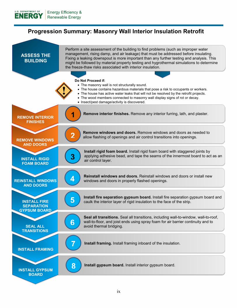
Progression Summary: Masonry Wall Interior Insulation Retrofit
INSTALL RIGID FOAM BOARD
Install rigid foam board. Install rigid foam board with staggered joints by applying adhesive bead, and tape the seams of the innermost board to act as an air control layer.
3
REINSTALL WINDOWS AND DOORS
Reinstall windows and doors. Reinstall windows and doors or install new windows and doors in properly flashed openings. 4
ASSESS THE BUILDING
Perform a site assessment of the building to find problems (such as improper water management, rising damp, and air leakage) that must be addressed before insulating. Fixing a leaking downspout is more important than any further testing and analysis. This might be followed by material property testing and hygrothermal simulations to determine the freeze-thaw risks associated with interior insulation.
!
INSTALL FIRE
SEPARATION GYPSUM BOARD
Install fire separation gypsum board. Install fire separation gypsum board and caulk the interior layer of rigid insulation to the face of the strip.
REMOVE INTERIOR FINISHES
Remove interior finishes. Remove any interior furring, lath, and plaster. 1
5
SEAL ALL TRANSITIONS
Seal all transitions. Seal all transitions, including wall-to-window, wall-to-roof, wall-to-floor, and joist ends using spray foam for air barrier continuity and to avoid thermal bridging.
Do Not Proceed if: • The masonry wall is not structurally sound. • The house contains hazardous materials that pose a risk to occupants or workers. • The house has active water leaks that will not be resolved by the retrofit projects. • The wood members connected to masonry wall display signs of rot or decay. • Insect/pest damage/activity is discovered.
REMOVE WINDOWS AND DOORS
Remove windows and doors. Remove windows and doors as needed to allow flashing of openings and air control transitions into openings.
2
6
INSTALL FRAMING Install framing. Install framing inboard of the insulation.
7
INSTALL GYPSUM BOARD
Install gypsum board. Install interior gypsum board.
8
ix
1 Introduction
This Measure Guideline provides design and construction information about a deep energy enclosure retrofit (DEER) solution for insulating mass masonry buildings on the interior. It describes the retrofit assembly and the strategies and procedures for an interior retrofit of masonry wall with rigid insulation.
An exterior retrofit is generally more favorable than an interior retrofit because it improves building durability by reducing the likelihood of cold weather condensation within the structure (Straube et al. 2012). Exterior retrofits are also less disruptive to the living space and typically allow a structure to remain occupied during the project.
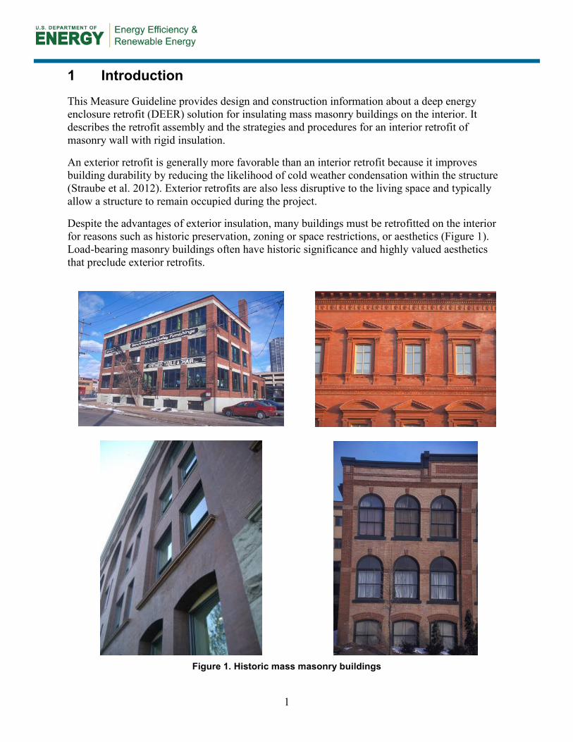
Despite the advantages of exterior insulation, many buildings must be retrofitted on the interior for reasons such as historic preservation, zoning or space restrictions, or aesthetics (Figure 1). Load-bearing masonry buildings often have historic significance and highly valued aesthetics that preclude exterior retrofits.
Figure 1. Historic mass masonry buildings
1
Interior retrofits of load-bearing masonry are often desired to preserve a building’s exterior appearance. Many possible interior insulation approaches are, by and large, reasonably well understood. Adding insulation, increasing airtightness, replacing windows, and improving rain control constitute a normal retrofit package. Adding insulation to the walls of such masonry buildings in cold (and particularly cold and wet) climates may cause performance and durability problems, particularly rot and freeze-thaw damage. Specific moisture control principles must be followed for a successful interior insulation retrofit of a solid load-bearing masonry wall (Straube et al. 2012). A retrofit that increases the building airtightness with interior insulation can cause indoor air quality problems; mechanical ventilation, pollution source control, and combustion safety measures must be implemented to manage the risk.
Numerous obstacles to wider scale deployment of interior retrofits include concerns about freeze-thaw damage caused by reduced outward heat flow and reduced inward drying, and the potential for decay of wood structural framing members (typically floor joists) that are embedded in mass assemblies. The problems and some case studies of interior retrofits are outlined by practitioners such as Gonçalves (2003), Maurenbrecher et al. (1998), Straube and Schumacher (2002, 2004), and Straube et al. (2012).
This Measure Guideline includes a review of decision criteria pertinent to retrofitting masonry walls from the interior and the possible risk of freeze-thaw damage. These criteria include cost and performance, durability, constructability, freeze-thaw degradation risk, air leakage performance, and thermal performance. This guideline also discusses fundamental building science and design principles for using interior insulation in masonry buildings, and construction detailing and procedures developed to provide understanding of how the various elements of the design are implemented.
This Measure Guideline is intended to support contractors who are implementing an interior insulation-based high-performance enclosure retrofit for masonry buildings and to support designers who are looking to design such retrofits. It may also be helpful to building owners who wish to learn more about strategies available for DEER of masonry residential buildings on the interior. Owners could also use the guideline to implement the retrofit strategy because this strategy is a low-tech application and involves few safety measures.
2
2 Decision-Making Criteria
This section discusses the major decision-making criteria once an interior retrofit has been decided on, after considering issues such as aesthetics, historic significance, improved comfort, and the lifespan of the project.
2.1 Cost and Performance Cost and performance are intricately linked and must be studied in combination to determine the best choice per the decision maker’s goals and objectives. Installation costs for the retrofit solution described in this Measure Guideline can vary widely from estimates in the referred sources, depending on such factors as contractor experience, prevalent region practices, material costs, and the particular circumstances of the project. The cost range sometimes varies by a factor of 5 to 10.
Suitable interior insulation options for the masonry building include XPS (extruded polystyrene) rigid insulation, closed cell spray polyurethane foam (ccSPF) at a weight of 2 lb/ft3, or a hybrid approach of ccSPF or XPS with fiberglass batt or cellulose insulation. These options can be compared in terms of the cost of materials and labor, constructability of the system, and the performance aspects of each option, to determine the best retrofit option. In many cases of insulation retrofits of load-bearing masonry buildings, the energy savings are less important to the owner than increased thermal comfort, controlled rain penetration, and good indoor air quality.
The cost and performance of the following options were considered and evaluated for the wall retrofit; R-values are summarized in Table 1. Similar analysis could be done for equivalent options such as expanded polystyrene or polyisocyanurate rigid insulation.
• Three layers of 2-in. XPS rigid insulation (2 × 4 stud wall inboard of insulation)
• Two layers of 2-in. XPS rigid insulation (2 × 4 stud wall inboard of insulation)
• 5-in. ccSPF (2 × 4 stud wall inboard of insulation)
• 2-in. ccSPF with 5-½-in. fiberglass batt (fiberglass in 2 × 6 stud wall inboard of ccSPF). Table 1. Cost Values for Wall Retrofit Options
Point Wall Retrofit Options R-Value RSMeans Cost Values*
1 6-in. XPS with 2 × 4 stud wall 31.5 $9.46/ft2 2 4-in. XPS with 2 × 4 stud wall 22.6 $7.47/ft2 5 5-in. ccSPF with 2 × 4 stud wall 31.1 $7.53/ft2 6 2-in. ccSPF+5-½-in. fiberglass batt with 2 × 6 stud wall 30.4 $5.92/ft2
*RSMeans Reed Construction Data 2012 (Reed 2012)
Each wall system has advantages and disadvantages. The disadvantage of using rigid sheet goods (such as XPS) compared to a monolithic material (such as spray foam) includes the challenges of establishing a continuous air barrier, because it requires ensuring that the board is firmly in contact with the masonry without any gaps, and the implementation of the drawn details. The
3
advantage of using rigid sheets, however, is that a homeowner can save significant costs by performing the installation.
Spraying 5-in. ccSPF onto the masonry walls contributes to the airtightness of the assembly and results in excellent condensation and vapor diffusion control. An industry professional must complete the work so it can be completed in a shorter time. The drawback, however, is the cost of material and labor (Ueno et al. 2013). Also, ccSPF installations beyond 2- to 3-in. thicknesses must be done in layers, which further increases the installation time and labor cost.
The option of spraying 2-in. ccSPF and installing batt insulation in the wall cavities creates a “hybrid” assembly that uses each material to its best advantage. The spray foam creates a robust air barrier and controls interstitial condensation risks while the batt insulation raises the R-value of the assembly. The fiberglass batt insulation is a more affordable product and can be installed by a homeowner; however, the ccSPF has a higher cost and the installation must be carried out by a professional.
Table 1 lists R-values and costs for the four compared exterior wall insulation options: 6-in. XPS rigid insulation, 4-in. XPS rigid insulation, 5-in. ccSPF, and 2-in. ccSPF with fiberglass batt insulation. The cost values were obtained from RSMeans Reed Construction Data 2012 (Reed 2012), a cost-estimating tool that provides the costs of materials and installation, and overhead and profit. The R-values listed in Table 1 were derived from earlier BEopt models (Christensen et al. 2006).
The cost-optimized wall system based on market rates for labor and materials is 2-in. ccSPF to the interior face of the masonry wall with 5-½-in. fiberglass batt insulation in a 2 × 6 framed wall. The 6-in. XPS with a 2 × 4 stud wall has the best thermal performance (by a small margin); it also involves low-tech construction techniques (making it relatively easy to implement), and was thus chosen for discussion in this Measure Guideline.
2.2 Durability Solid load-bearing masonry assemblies are durable. However, the manner in which they manage moisture is quite different than modern, framed, multilayer assemblies. The difference in behavior must be understood to support decision-making during retrofits.
The primary concerns with insulating older load-bearing masonry buildings in cold climates are (1) the possibility of causing freeze-thaw damage of the brickwork and (2) decay in any embedded wood structure. Both problems are caused by excess moisture. Other durability concerns about interior insulation retrofits are that the assembly will reduce drying to the interior and that the amount of energy flow through the wall (and thus the drying potential) will be minimized. An additional durability risk is that bulk water entry will not be as evident from interior inspection in the post-retrofit building.
BEopt Economic Analysis BEopt is the Building America performance analysis tool that features options for retrofit projects. It is used to analyze the energy use and the cost-effectiveness of the wall retrofit measures considered. BEopt could be used to provide an economic analysis that is representative of a typical construction market. See https://beopt.nrel.gov for more information.
4

Yet another concern is the rot and corrosion of embedded elements (e.g., wood joists and reinforcing steel). The most significant issues with embedded joist durability are related to bulk water problems, such as excess deposition on the wall, cracks in the façade (allowing leakage), and proximity to grade (or worse, below-grade conditions). If any of these issues are found in the site inspection, they must be addressed before an interior insulation retrofit is considered.
A counteracting aspect of this issue with interior insulation retrofits is that although the assembly may have higher moisture content, it is also much colder during winter months, which slows the rate of corrosion (chemical reactions) and rot (biological reactions) (Straube et al. 2012).
2.3 Constructability The ease of construction might be a consideration, depending on the specific requirement of the decision maker. For larger projects with higher budgets, trained professionals can be hired to perform complicated jobs. But for smaller projects in which the building owners wish to perform the retrofit, options that involve low-tech construction techniques and that are easier to implement should be considered. Among the options listed in Table 1, the interior retrofit options consisting of XPS with stud wall are relatively easy to implement and do not require trained professionals.
2.4 Freeze-Thaw Degradation Risk
For existing mass masonry walls, a site assessment must be performed to examine the building’s water management features and look for evidence of damage and water penetration. Problems will be exacerbated by interior insulation. The brick material properties may then be tested to ensure that the wall can be retrofitted without durability problems (Straube et al. 2012). This involves material property testing (laboratory testing of sample bricks), and hygrothermal computer simulations to diagnose the cause of current issues and predict the effect of an interior insulation retrofit. Straube et al. (2012) provide further information about the testing procedures.
The brick analysis ensures that high levels of interior insulation do not present a risk of freeze-thaw damage to the mass masonry walls. The freeze-thaw degradation risk is assessed by predicting the masonry moisture content during incidents when the material temperature drops below 23°F (–5°C) (Ueno et al. 2013). Individual sample bricks are collected from the interior and exterior of the original building, followed by material property testing to assess freeze-thaw risk. Testing includes that for dry density, water absorption coefficient (A-value), free water
WUFI Hygrothermal Analysis The WUFI hygrothermal computer simulation model can be used to simulate the effects of insulating the walls on the moisture and temperature conditions of the masonry walls. WUFI is one of the most advanced commercially available hygrothermal moisture programs in use today. Its accuracy has been verified (by the Fraunhofer Institut für Bauphysik in Holzkirchen, Germany) against numerous full-scale field studies of enclosure performance (roofs, walls, foundations, parking garage decks, etc.) over a number of years. Much of the field verification work supporting the model has been on solid masonry wall systems. WUFI is one of the few models in the public domain that can properly account for rain absorption and water absorption/redistribution for arbitrary material data and boundary conditions. Given the appropriate material data, WUFI calculates heat and moisture flow every hour under the influence of sun, rain, temperature, and humidity. The analysis is, however, only as accurate as the assembly data, the material properties, and the interior and exterior conditions input.
5
saturation, and vacuum saturation. Testers also determine the critical degree of saturation (Scrit), which reflects a brick’s resistance to freeze-thaw damage; relatively high Scrit values (~0.75–0.80) indicate good resistance to damage. The measured values are then used in WUFI simulations to predict the brick moisture content during freezing conditions for the existing and proposed retrofit wall assemblies under varying rain exposures.
2.5 Air Leakage Performance Designing a retrofit assembly that allows significant air leakage is very risky; therefore, the air leakage performance of the retrofit strategies must be evaluated before a decision is made. However, experience has shown that air barrier systems formed by careful taping, caulking, spray polyurethane products, and fully adhered membranes are quite likely to achieve airtightness when properly installed using standard quality control measures. In general, air leakage across the enclosure is assumed to have been essentially controlled by appropriate air sealing materials and techniques, such as taping the joints of the rigid insulation’s innermost and outermost layers and using interior spray foam insulation.
2.6 Thermal Performance The decision about the thermal performance depends on the specific requirements of the project. For projects that need to meet stringent energy performance goals, a higher level of insulation must be provided.
Thermal insulation follows the law of diminishing returns; return on investment decreases with increasing insulation thickness. Given that the wall assemblies are changed from uninsulated to insulated assemblies, the initial 1–2 in. of insulation should be highly cost-effective. Optimization is a function of insulation cost, climate zone, and energy costs.
6

3 Technical Description
3.1 Masonry Wall Interior Insulation Retrofit Assembly The retrofit assembly consists of three 2-in. layers of rigid foam insulation (with staggered seams), adhered to the masonry and between layers with a single-component polyurethane adhesive. The innermost layer of rigid insulation (closest to the interior) has joints taped to create an air barrier. Wood 2 × 4 framing is installed inboard of these layers with no insulation in the stud bay cavities to allow installation of the interior finishes and to provide space for running services (Figure 2).
7

Figure 2. Bearing masonry interior insulation retrofit approach
8

3.2 System Interaction If an interior retrofit improves the insulation value and airtightness, numerous risks must be assessed. Both improvements may reduce the durability of the masonry, which will be colder for longer periods of time than before and will have less drying capacity, both because it is colder and because the interior layers added by the retrofit will restrict vapor diffusion. The colder post-retrofit masonry will also make air leakage condensation much more likely in cold weather. The retrofit solution outlined in this Measure Guideline includes robust air control measures in addition to high R-value thermal performance. The performance of the bearing masonry interior insulation retrofit solution relative to critical control functions is described in the following sections.
3.2.1 Water Control Controlling bulk water entry into the wall when executing interior retrofits is crucial, especially because water leakage will no longer be visible from the inside until the interior finishes are damaged. If rain control cannot be addressed and upgraded, interior insulation should not be implemented (Straube et al. 2012).
In most walls, a water control layer protects the structure. Water control layers are water-repellent materials (building paper, housewrap, sheet membranes, liquid-applied coatings, or taped and sealed rigid insulation boards) that are located behind the cladding and are designed and constructed to drain water that passes through the cladding. They are interconnected with flashings, window and door openings, and other penetrations of the building enclosure to provide drainage to the exterior. The materials that form the water control layer—in this case the innermost rigid insulation board behind the masonry wall—overlap shingle fashion or are sealed so that water drains down and out of the wall (see Figure 3). The water control layer is often referred to as the drainage plane or water-resistant barrier or water control layer.
Figure 3. The “down” and “out” approach to flashing
The manner in which load-bearing masonry walls manage water is quite different from how modern, framed, multilayer assemblies manage water. Mass masonry walls absorb and safely store water during precipitation, and later dry during more advantageous conditions. Solid masonry walls may contain many hollow spaces or voids (Figure 4), which act as capillary breaks, and may allow water to accumulate or concentrate, because they are invariably not intentionally drained. Guidance for key details and conditions to address are covered by Straube et al. (2012).
9
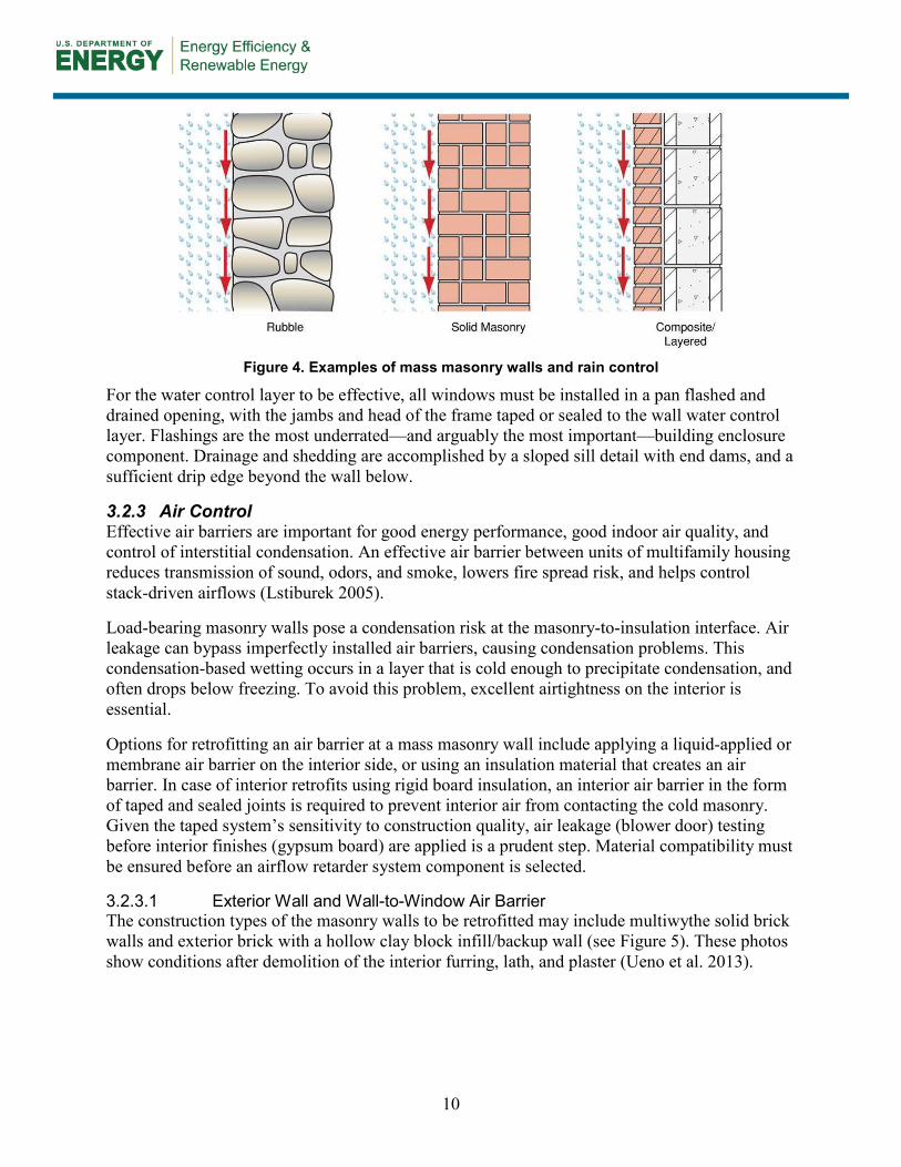
Figure 4. Examples of mass masonry walls and rain control
For the water control layer to be effective, all windows must be installed in a pan flashed and drained opening, with the jambs and head of the frame taped or sealed to the wall water control layer. Flashings are the most underrated—and arguably the most important—building enclosure component. Drainage and shedding are accomplished by a sloped sill detail with end dams, and a sufficient drip edge beyond the wall below.
3.2.3 Air Control Effective air barriers are important for good energy performance, good indoor air quality, and control of interstitial condensation. An effective air barrier between units of multifamily housing reduces transmission of sound, odors, and smoke, lowers fire spread risk, and helps control stack-driven airflows (Lstiburek 2005).
Load-bearing masonry walls pose a condensation risk at the masonry-to-insulation interface. Air leakage can bypass imperfectly installed air barriers, causing condensation problems. This condensation-based wetting occurs in a layer that is cold enough to precipitate condensation, and often drops below freezing. To avoid this problem, excellent airtightness on the interior is essential.
Options for retrofitting an air barrier at a mass masonry wall include applying a liquid-applied or membrane air barrier on the interior side, or using an insulation material that creates an air barrier. In case of interior retrofits using rigid board insulation, an interior air barrier in the form of taped and sealed joints is required to prevent interior air from contacting the cold masonry. Given the taped system’s sensitivity to construction quality, air leakage (blower door) testing before interior finishes (gypsum board) are applied is a prudent step. Material compatibility must be ensured before an airflow retarder system component is selected.
3.2.3.1 Exterior Wall and Wall-to-Window Air Barrier The construction types of the masonry walls to be retrofitted may include multiwythe solid brick walls and exterior brick with a hollow clay block infill/backup wall (see Figure 5). These photos show conditions after demolition of the interior furring, lath, and plaster (Ueno et al. 2013).
10
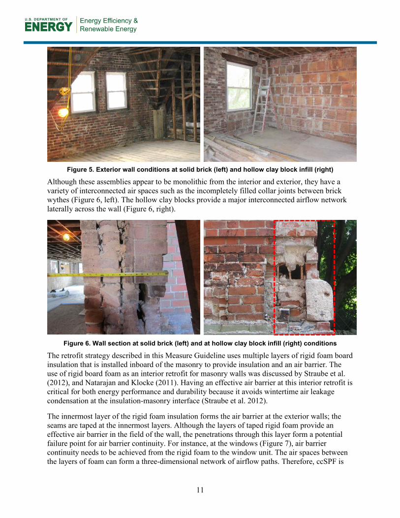
Figure 5. Exterior wall conditions at solid brick (left) and hollow clay block infill (right)
Although these assemblies appear to be monolithic from the interior and exterior, they have a variety of interconnected air spaces such as the incompletely filled collar joints between brick wythes (Figure 6, left). The hollow clay blocks provide a major interconnected airflow network laterally across the wall (Figure 6, right).
Figure 6. Wall section at solid brick (left) and at hollow clay block infill (right) conditions
The retrofit strategy described in this Measure Guideline uses multiple layers of rigid foam board insulation that is installed inboard of the masonry to provide insulation and an air barrier. The use of rigid board foam as an interior retrofit for masonry walls was discussed by Straube et al. (2012), and Natarajan and Klocke (2011). Having an effective air barrier at this interior retrofit is critical for both energy performance and durability because it avoids wintertime air leakage condensation at the insulation-masonry interface (Straube et al. 2012).
The innermost layer of the rigid foam insulation forms the air barrier at the exterior walls; the seams are taped at the innermost layers. Although the layers of taped rigid foam provide an effective air barrier in the field of the wall, the penetrations through this layer form a potential failure point for air barrier continuity. For instance, at the windows (Figure 7), air barrier continuity needs to be achieved from the rigid foam to the window unit. The air spaces between the layers of foam can form a three-dimensional network of airflow paths. Therefore, ccSPF is
11
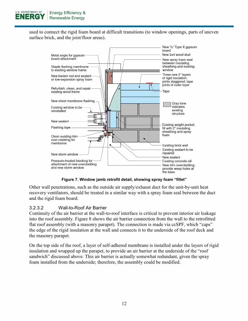
used to connect the rigid foam board at difficult transitions (to window openings, parts of uneven surface brick, and the joist/floor areas).
Figure 7. Window jamb retrofit detail, showing spray foam “fillet”
Other wall penetrations, such as the outside air supply/exhaust duct for the unit-by-unit heat recovery ventilators, should be treated in a similar way with a spray foam seal between the duct and the rigid foam board.
3.2.3.2 Wall-to-Roof Air Barrier Continuity of the air barrier at the wall-to-roof interface is critical to prevent interior air leakage into the roof assembly. Figure 8 shows the air barrier connection from the wall to the retrofitted flat roof assembly (with a masonry parapet). The connection is made via ccSPF, which “caps” the edge of the rigid insulation at the wall and connects it to the underside of the roof deck and the masonry parapet.
On the top side of the roof, a layer of self-adhered membrane is installed under the layers of rigid insulation and wrapped up the parapet, to provide an air barrier at the underside of the “roof sandwich” discussed above. This air barrier is actually somewhat redundant, given the spray foam installed from the underside; therefore, the assembly could be modified.
12
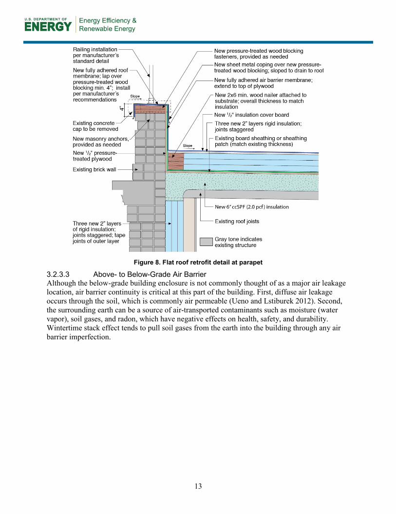
Figure 8. Flat roof retrofit detail at parapet
3.2.3.3 Above- to Below-Grade Air Barrier Although the below-grade building enclosure is not commonly thought of as a major air leakage location, air barrier continuity is critical at this part of the building. First, diffuse air leakage occurs through the soil, which is commonly air permeable (Ueno and Lstiburek 2012). Second, the surrounding earth can be a source of air-transported contaminants such as moisture (water vapor), soil gases, and radon, which have negative effects on health, safety, and durability. Wintertime stack effect tends to pull soil gases from the earth into the building through any air barrier imperfection.
13
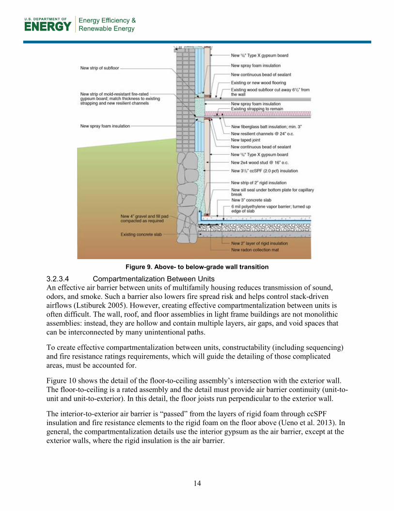
Figure 9. Above- to below-grade wall transition
3.2.3.4 Compartmentalization Between Units An effective air barrier between units of multifamily housing reduces transmission of sound, odors, and smoke. Such a barrier also lowers fire spread risk and helps control stack-driven airflows (Lstiburek 2005). However, creating effective compartmentalization between units is often difficult. The wall, roof, and floor assemblies in light frame buildings are not monolithic assemblies: instead, they are hollow and contain multiple layers, air gaps, and void spaces that can be interconnected by many unintentional paths.
To create effective compartmentalization between units, constructability (including sequencing) and fire resistance ratings requirements, which will guide the detailing of those complicated areas, must be accounted for.
Figure 10 shows the detail of the floor-to-ceiling assembly’s intersection with the exterior wall. The floor-to-ceiling is a rated assembly and the detail must provide air barrier continuity (unit-to-unit and unit-to-exterior). In this detail, the floor joists run perpendicular to the exterior wall.
The interior-to-exterior air barrier is “passed” from the layers of rigid foam through ccSPF insulation and fire resistance elements to the rigid foam on the floor above (Ueno et al. 2013). In general, the compartmentalization details use the interior gypsum as the air barrier, except at the exterior walls, where the rigid insulation is the air barrier.
14
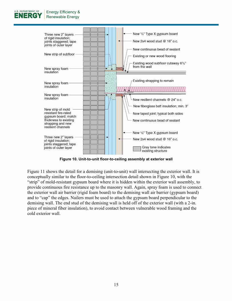
Figure 10. Unit-to-unit floor-to-ceiling assembly at exterior wall
Figure 11 shows the detail for a demising (unit-to-unit) wall intersecting the exterior wall. It is conceptually similar to the floor-to-ceiling intersection detail shown in Figure 10, with the “strip” of mold-resistant gypsum board where it is hidden within the exterior wall assembly, to provide continuous fire resistance up to the masonry wall. Again, spray foam is used to connect the exterior wall air barrier (rigid foam board) to the demising wall air barrier (gypsum board) and to “cap” the edges. Nailers must be used to attach the gypsum board perpendicular to the demising wall. The end stud of the demising wall is held off of the exterior wall (with a 2-in. piece of mineral fiber insulation), to avoid contact between vulnerable wood framing and the cold exterior wall.
15
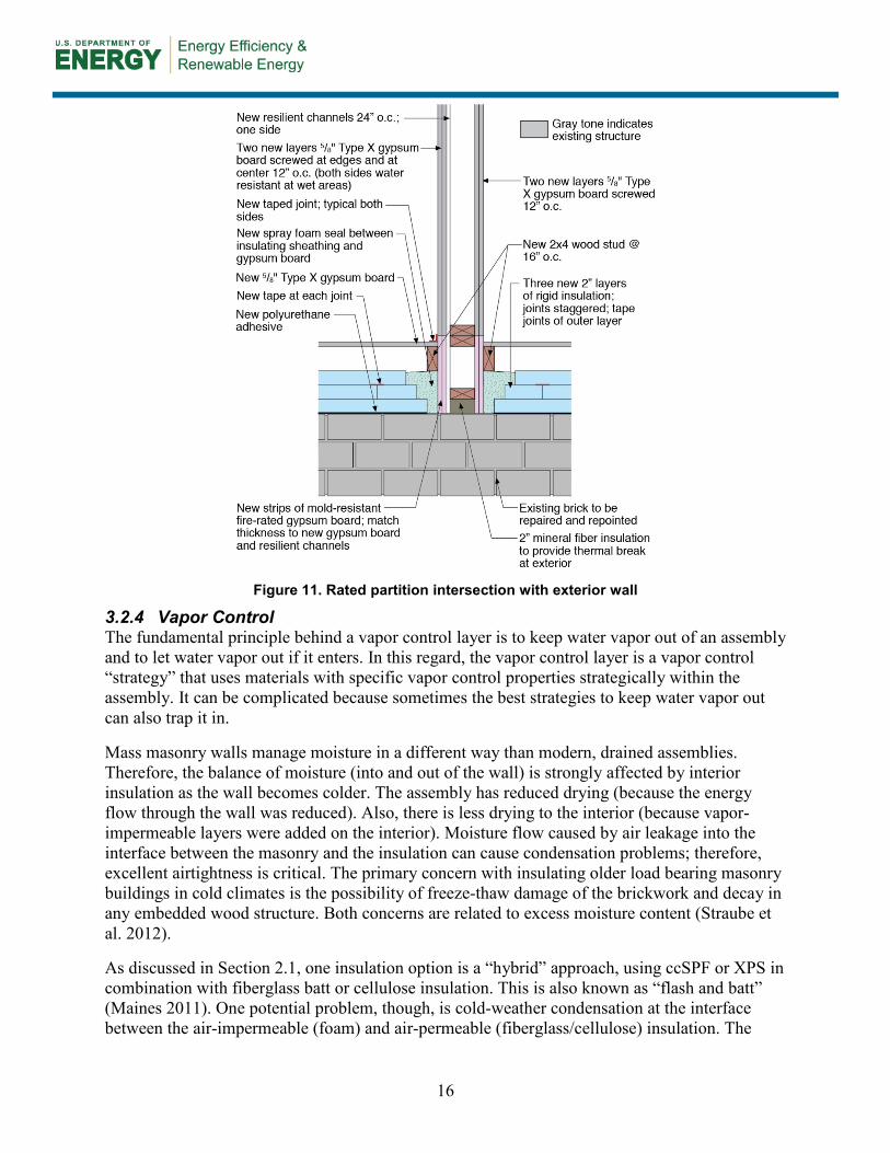
Figure 11. Rated partition intersection with exterior wall
3.2.4 Vapor Control The fundamental principle behind a vapor control layer is to keep water vapor out of an assembly and to let water vapor out if it enters. In this regard, the vapor control layer is a vapor control “strategy” that uses materials with specific vapor control properties strategically within the assembly. It can be complicated because sometimes the best strategies to keep water vapor out can also trap it in.
Mass masonry walls manage moisture in a different way than modern, drained assemblies. Therefore, the balance of moisture (into and out of the wall) is strongly affected by interior insulation as the wall becomes colder. The assembly has reduced drying (because the energy flow through the wall was reduced). Also, there is less drying to the interior (because vapor-impermeable layers were added on the interior). Moisture flow caused by air leakage into the interface between the masonry and the insulation can cause condensation problems; therefore, excellent airtightness is critical. The primary concern with insulating older load bearing masonry buildings in cold climates is the possibility of freeze-thaw damage of the brickwork and decay in any embedded wood structure. Both concerns are related to excess moisture content (Straube et al. 2012).
As discussed in Section 2.1, one insulation option is a “hybrid” approach, using ccSPF or XPS in combination with fiberglass batt or cellulose insulation. This is also known as “flash and batt” (Maines 2011). One potential problem, though, is cold-weather condensation at the interface between the air-impermeable (foam) and air-permeable (fiberglass/cellulose) insulation. The
16
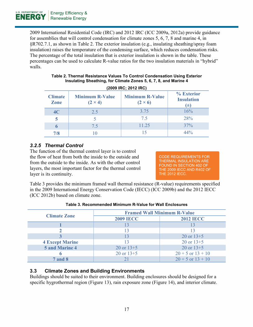
2009 International Residential Code (IRC) and 2012 IRC (ICC 2009a, 2012a) provide guidance for assemblies that will control condensation for climate zones 5, 6, 7, 8 and marine 4, in §R702.7.1, as shown in Table 2. The exterior insulation (e.g., insulating sheathing/spray foam insulation) raises the temperature of the condensing surface, which reduces condensation risks. The percentage of the total insulation that is exterior insulation is shown in the table. These percentages can be used to calculate R-value ratios for the two insulation materials in “hybrid” walls.
Table 2. Thermal Resistance Values To Control Condensation Using Exterior Insulating Sheathing, for Climate Zones 5, 6, 7, 8, and Marine 4
(2009 IRC; 2012 IRC)
Climate Zone
Minimum R-Value (2 × 4)
Minimum R-Value (2 × 6)
% Exterior Insulation
(±) 4C 2.5 3.75 16% 5 5 7.5 28% 6 7.5 11.25 37%
7/8 10 15 44% 3.2.5 Thermal Control The function of the thermal control layer is to control the flow of heat from both the inside to the outside and from the outside to the inside. As with the other control layers, the most important factor for the thermal control layer is its continuity.
Table 3 provides the minimum framed wall thermal resistance (R-value) requirements specified in the 2009 International Energy Conservation Code (IECC) (ICC 2009b) and the 2012 IECC (ICC 2012b) based on climate zone.
Table 3. Recommended Minimum R-Value for Wall Enclosures
Climate Zone Framed Wall Minimum R-Value 2009 IECC 2012 IECC
1 13 13 2 13 13 3 13 20 or 13+5
4 Except Marine 13 20 or 13+5 5 and Marine 4 20 or 13+5 20 or 13+5
6 20 or 13+5 20 + 5 or 13 + 10 7 and 8 21 20 + 5 or 13 + 10
3.3 Climate Zones and Building Environments Buildings should be suited to their environment. Building enclosures should be designed for a specific hygrothermal region (Figure 13), rain exposure zone (Figure 14), and interior climate.
CODE REQUIREMENTS FOR THERMAL INSULATION ARE FOUND IN SECTION 402 OF THE 2009 IECC AND R402 OF THE 2012 IECC.
17
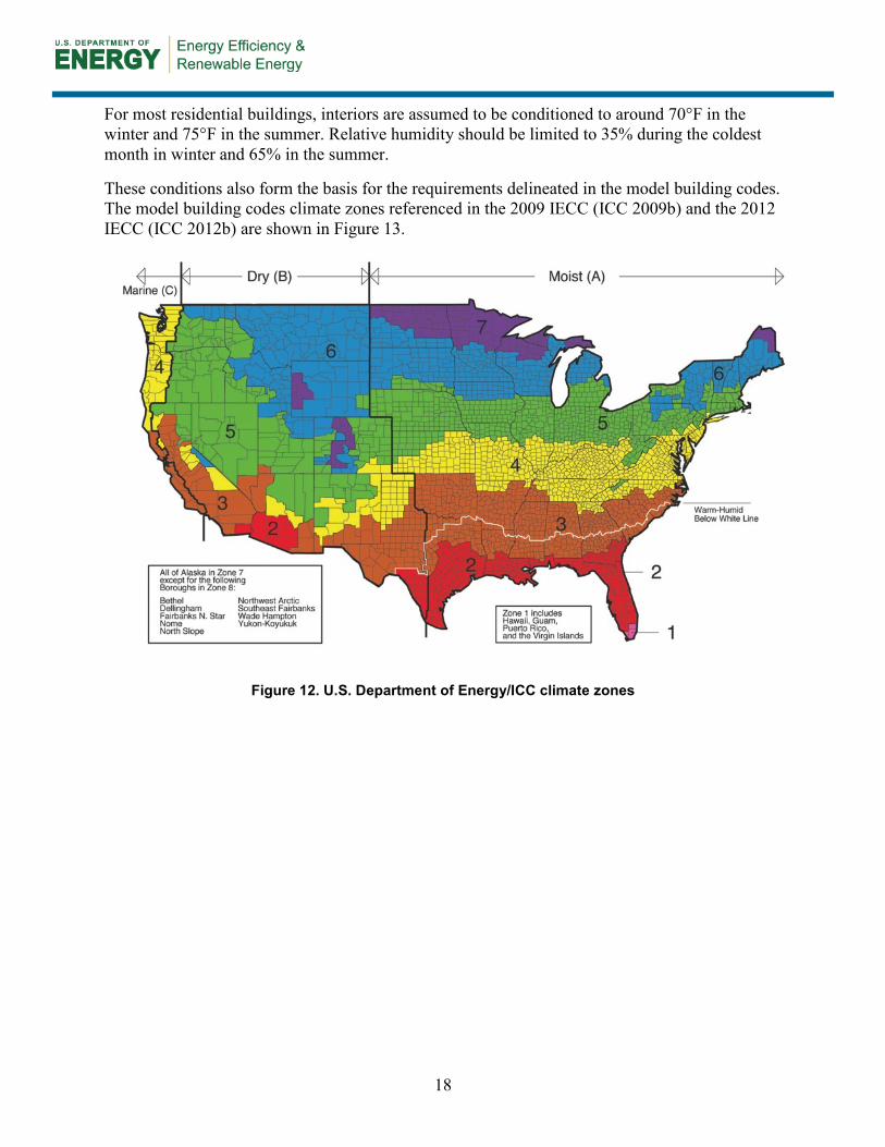
For most residential buildings, interiors are assumed to be conditioned to around 70°F in the winter and 75°F in the summer. Relative humidity should be limited to 35% during the coldest month in winter and 65% in the summer.
These conditions also form the basis for the requirements delineated in the model building codes. The model building codes climate zones referenced in the 2009 IECC (ICC 2009b) and the 2012 IECC (ICC 2012b) are shown in Figure 13.
Figure 12. U.S. Department of Energy/ICC climate zones
18

Figure 13. Hygrothermal map
(Lstiburek 2006a)
19
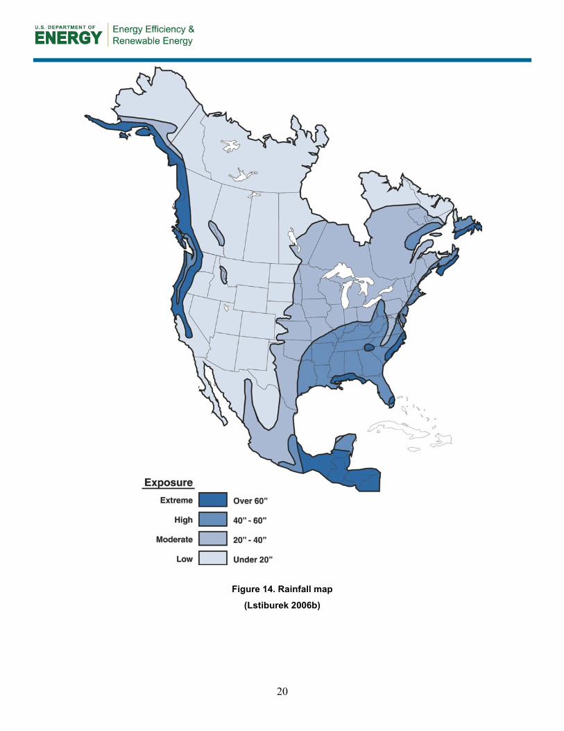
Figure 14. Rainfall map
(Lstiburek 2006b)
20
4 Measure Implementation
4.1 Scope of Work
4.2 Climate-Specific Factors The building enclosures should be designed for a specific hygrothermal region and depend on the project’s design goals. The assemblies should follow the minimum requirements based on the current adopted building code and energy code, respectively, for the project.
4.3 Field Inspection A field inspection consists of the following steps:
1. Identify and address risks to occupants or the building that could be aggravated by thework.
2. Verify safe working conditions.
3. Determine whether the building has more urgent problems that must be addressed.
4. Determine the feasibility of the retrofit solution and of options.
5. Inspect and assess the building for:
A. Structural integrity of masonry wall
B. Hazardous materials (e.g., lead, radon, asbestos)
C. Rainwater, groundwater, or plumbing water leaks
D. Rot or decay in wood members connected to masonry wall
E. Insect and pest damage and activity.
6. Remediate any deficiencies or hazards before the project begins, or incorporate this stepinto the scope of the project.
7. Identify any atmospherically vented (or naturally aspirated) combustion appliances in thehome. With the exception of gas stoves and cooktops, combustion appliances—includingfireplaces—should be direct-vented or direct exhaust-vented equipment. Atmospherically
21
A. Remove any interior furring, lath, and plaster. B. Remove windows and doors as needed to allow flashing of openings and air control
transitions into openings. C. Install rigid foam board with staggered joints by applying adhesive bead and tape the seams
of the innermost board to act as an air control layer. D. Reinstall windows and doors or install new windows and doors in properly flashed openings. E. In multifamily construction, install fire separation gypsum board and caulk the interior layer of
rigid insulation to the face of the strip. F. Seal all transitions, including wall-to-window, wall-to-roof, wall-to-floor, and joist ends using
spray foam for air barrier continuity and to avoid thermal bridging. G. Install framing inboard of the insulation. H. Install interior gypsum board.
vented appliances must be replaced or reconfigured to direct-vented or direct exhaust-vented operation before the project begins, or as part of the project scope.
8. Verify that all kitchen and bathroom exhausts are vented to the exterior. Correct any source control ventilation deficiencies either before or as part of the project.
9. If the home’s ventilation system does not meet the requirements of the 2012 IRC (2012 IRC, ICC 2012a), Section M1507.3, install a ventilation system that meets this requirement either before or as part of the project.
4.4 Implementation Risks Construction and renovation work entails inherent risks to workers. All applicable safety procedures must be followed. Although the low-tech retrofit solution described in this Measure Guideline does not involve high risks, it does involve the use of adhesives and cutting foam. Therefore, the authors recommend that all workers handling or cutting material:
• Wear protective clothing and avoid exposed skin.
• Wear goggles or similar enclosed eye protection.
• Wear gloves.
• Avoid spraying foam on areas not intended to be spray foamed.
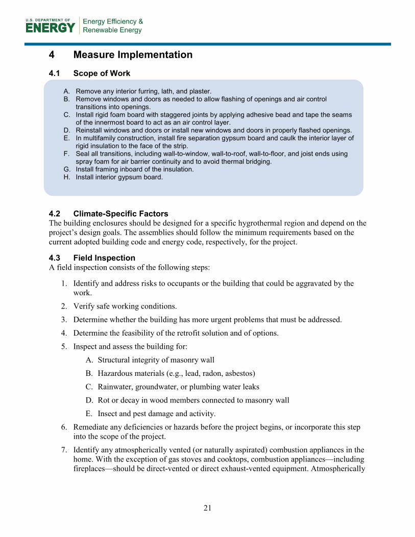
4.5 Installation Procedure 4.5.1. Remove Any Interior Furring, Lath, and Plaster The interior of masonry walls may be finished with plaster, which is often gypsum or lime-cement based. Sometimes it is installed over furring strips or lath, or both. In some cases, a layer of bitumen is applied between the interior finish and the masonry. Remove any interior furring, lath, and plaster to expose the brick structure from the interior for retrofit because they could be moisture sensitive (such as gypsum) or form a void that can create unintentional air leakage (such as furring and lath). Clean the brick to allow for reasonable adhesion of insulation (spray foam or rigid board). Conduct a site assessment to ensure that the building is suitable for retrofit; consider collecting brick samples for laboratory assessment of freeze-thaw degradation risk.
Figure 15. Interior furring, lath, and plaster removed
22
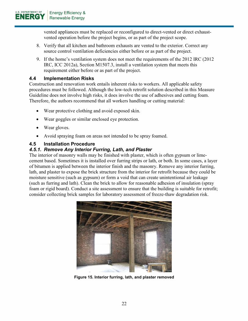
4.5.2 Remove Windows and Doors as Needed To Allow Flashing of Openings and Air Control Transitions Into Openings
Remove all windows and doors to allow flashing of openings and air control transitions into openings.
Figure 16. Removal of window (left) and window removed (right)
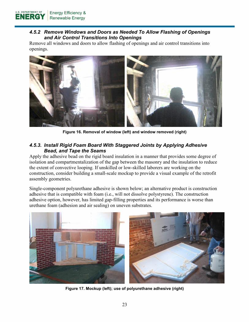
4.5.3. Install Rigid Foam Board With Staggered Joints by Applying Adhesive
Bead, and Tape the Seams Apply the adhesive bead on the rigid board insulation in a manner that provides some degree of isolation and compartmentalization of the gap between the masonry and the insulation to reduce the extent of convective looping. If unskilled or low-skilled laborers are working on the construction, consider building a small-scale mockup to provide a visual example of the retrofit assembly geometries.
Single-component polyurethane adhesive is shown below; an alternative product is construction adhesive that is compatible with foam (i.e., will not dissolve polystyrene). The construction adhesive option, however, has limited gap-filling properties and its performance is worse than urethane foam (adhesion and air sealing) on uneven substrates.
Figure 17. Mockup (left); use of polyurethane adhesive (right)
23
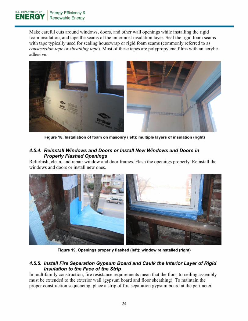
Make careful cuts around windows, doors, and other wall openings while installing the rigid foam insulation, and tape the seams of the innermost insulation layer. Seal the rigid foam seams with tape typically used for sealing housewrap or rigid foam seams (commonly referred to as construction tape or sheathing tape). Most of these tapes are polypropylene films with an acrylic adhesive.
Figure 18. Installation of foam on masonry (left); multiple layers of insulation (right)
4.5.4. Reinstall Windows and Doors or Install New Windows and Doors in
Properly Flashed Openings Refurbish, clean, and repair window and door frames. Flash the openings properly. Reinstall the windows and doors or install new ones.
Figure 19. Openings properly flashed (left); window reinstalled (right)
4.5.5. Install Fire Separation Gypsum Board and Caulk the Interior Layer of Rigid
Insulation to the Face of the Strip In multifamily construction, fire resistance requirements mean that the floor-to-ceiling assembly must be extended to the exterior wall (gypsum board and floor sheathing). To maintain the proper construction sequencing, place a strip of fire separation gypsum board at the perimeter
24
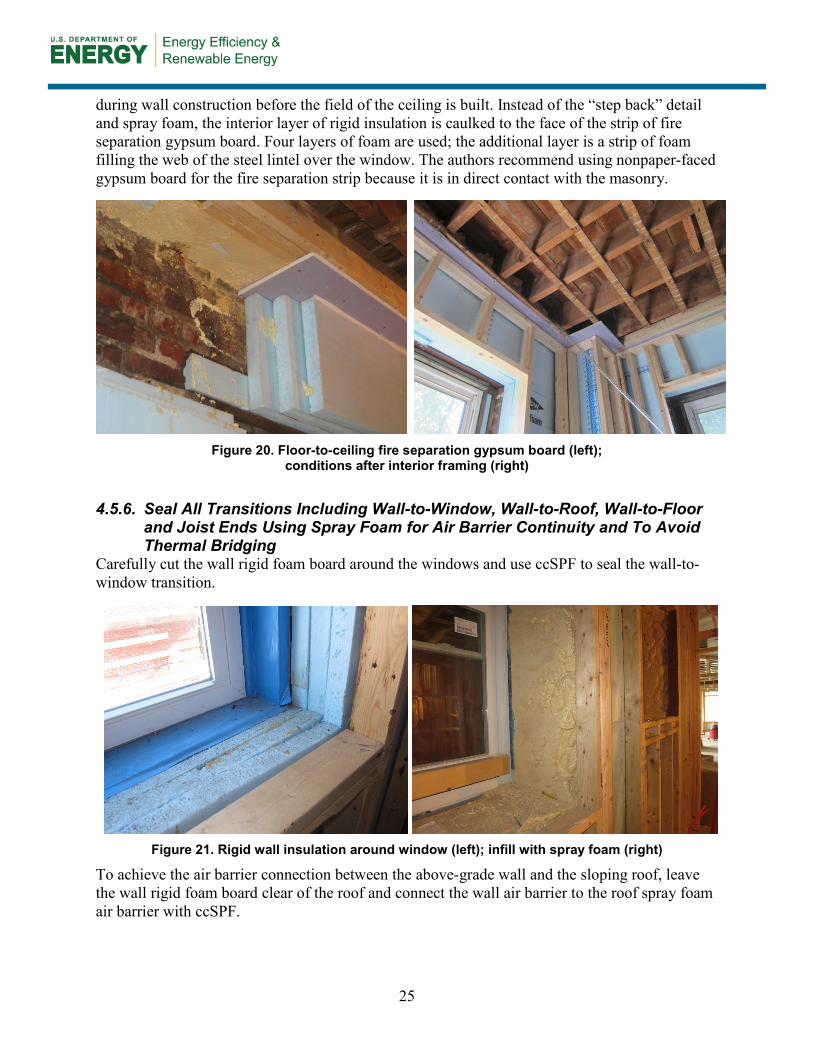
during wall construction before the field of the ceiling is built. Instead of the “step back” detail and spray foam, the interior layer of rigid insulation is caulked to the face of the strip of fire separation gypsum board. Four layers of foam are used; the additional layer is a strip of foam filling the web of the steel lintel over the window. The authors recommend using nonpaper-faced gypsum board for the fire separation strip because it is in direct contact with the masonry.
Figure 20. Floor-to-ceiling fire separation gypsum board (left);
conditions after interior framing (right)
4.5.6. Seal All Transitions Including Wall-to-Window, Wall-to-Roof, Wall-to-Floor
and Joist Ends Using Spray Foam for Air Barrier Continuity and To Avoid Thermal Bridging
Carefully cut the wall rigid foam board around the windows and use ccSPF to seal the wall-to-window transition.
Figure 21. Rigid wall insulation around window (left); infill with spray foam (right)
To achieve the air barrier connection between the above-grade wall and the sloping roof, leave the wall rigid foam board clear of the roof and connect the wall air barrier to the roof spray foam air barrier with ccSPF.
25
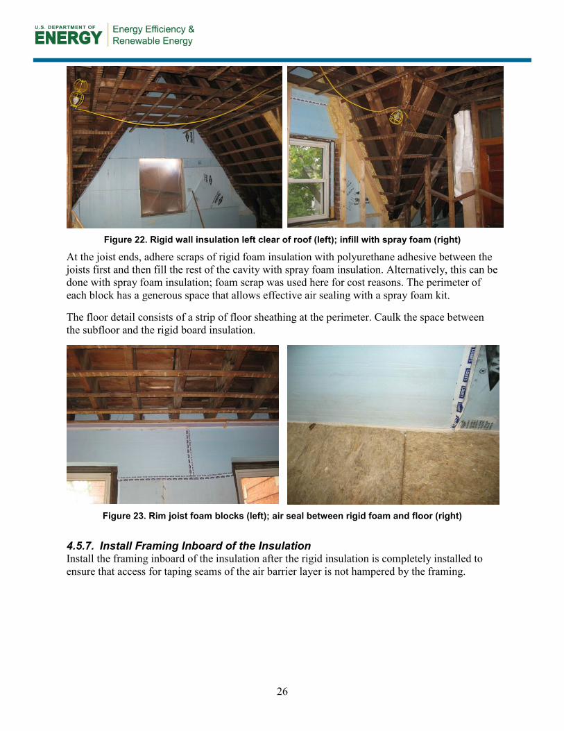
Figure 22. Rigid wall insulation left clear of roof (left); infill with spray foam (right)
At the joist ends, adhere scraps of rigid foam insulation with polyurethane adhesive between the joists first and then fill the rest of the cavity with spray foam insulation. Alternatively, this can be done with spray foam insulation; foam scrap was used here for cost reasons. The perimeter of each block has a generous space that allows effective air sealing with a spray foam kit.
The floor detail consists of a strip of floor sheathing at the perimeter. Caulk the space between the subfloor and the rigid board insulation.
Figure 23. Rim joist foam blocks (left); air seal between rigid foam and floor (right)
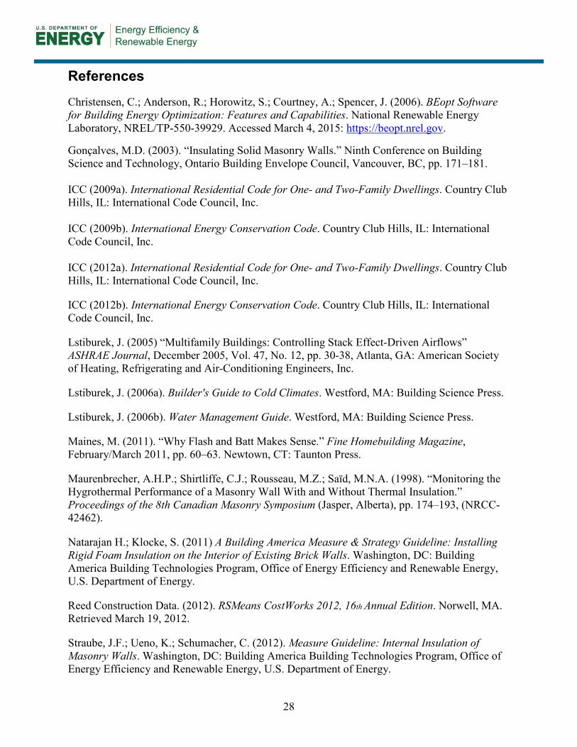
4.5.7. Install Framing Inboard of the Insulation Install the framing inboard of the insulation after the rigid insulation is completely installed to ensure that access for taping seams of the air barrier layer is not hampered by the framing.
26
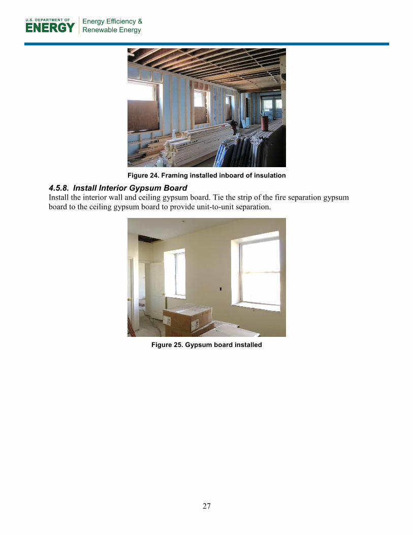
Figure 24. Framing installed inboard of insulation
4.5.8. Install Interior Gypsum Board Install the interior wall and ceiling gypsum board. Tie the strip of the fire separation gypsum board to the ceiling gypsum board to provide unit-to-unit separation.
Figure 25. Gypsum board installed
27
References
Christensen, C.; Anderson, R.; Horowitz, S.; Courtney, A.; Spencer, J. (2006). BEopt Software for Building Energy Optimization: Features and Capabilities. National Renewable Energy Laboratory, NREL/TP-550-39929. Accessed March 4, 2015: https://beopt.nrel.gov.
Gonçalves, M.D. (2003). “Insulating Solid Masonry Walls.” Ninth Conference on Building Science and Technology, Ontario Building Envelope Council, Vancouver, BC, pp. 171–181. ICC (2009a). International Residential Code for One- and Two-Family Dwellings. Country Club Hills, IL: International Code Council, Inc. ICC (2009b). International Energy Conservation Code. Country Club Hills, IL: International Code Council, Inc. ICC (2012a). International Residential Code for One- and Two-Family Dwellings. Country Club Hills, IL: International Code Council, Inc.
ICC (2012b). International Energy Conservation Code. Country Club Hills, IL: International Code Council, Inc.
Lstiburek, J. (2005) “Multifamily Buildings: Controlling Stack Effect-Driven Airflows” ASHRAE Journal, December 2005, Vol. 47, No. 12, pp. 30-38, Atlanta, GA: American Society of Heating, Refrigerating and Air-Conditioning Engineers, Inc.
Lstiburek, J. (2006a). Builder's Guide to Cold Climates. Westford, MA: Building Science Press.
Lstiburek, J. (2006b). Water Management Guide. Westford, MA: Building Science Press.
Maines, M. (2011). “Why Flash and Batt Makes Sense.” Fine Homebuilding Magazine, February/March 2011, pp. 60–63. Newtown, CT: Taunton Press.
Maurenbrecher, A.H.P.; Shirtliffe, C.J.; Rousseau, M.Z.; Saïd, M.N.A. (1998). “Monitoring the Hygrothermal Performance of a Masonry Wall With and Without Thermal Insulation.” Proceedings of the 8th Canadian Masonry Symposium (Jasper, Alberta), pp. 174–193, (NRCC-42462).
Natarajan H.; Klocke, S. (2011) A Building America Measure & Strategy Guideline: Installing Rigid Foam Insulation on the Interior of Existing Brick Walls. Washington, DC: Building America Building Technologies Program, Office of Energy Efficiency and Renewable Energy, U.S. Department of Energy.
Reed Construction Data. (2012). RSMeans CostWorks 2012, 16th Annual Edition. Norwell, MA. Retrieved March 19, 2012.
Straube, J.F.; Ueno, K.; Schumacher, C. (2012). Measure Guideline: Internal Insulation of Masonry Walls. Washington, DC: Building America Building Technologies Program, Office of Energy Efficiency and Renewable Energy, U.S. Department of Energy.
28

Straube, J.F.; Schumacher, C.J. (2002). Comparison of Monitored and Modeled Envelope Performance for a Solid Masonry Building. CMHC Report, Ottawa.
Straube, J.F.; Schumacher, C.J. (2004). Hygrothermal Modeling of Building Envelopes Retrofits. CMHC Report, Ottawa.
Ueno, K.; Kerrigan, P.; Wytrykowska, H.; Van Straaten, R. (2013). Retrofit of a Multifamily Mass Masonry Building in New England. Golden, CO: National Renewable Energy Laboratory, DOE/GO-102013-3919.
Ueno, K.; Lstiburek, J. (2012). A Building America Measure & Strategy Guideline: Hybrid Foundation Insulation Retrofits. Washington, DC: Building America Building Technologies Program, Office of Energy Efficiency and Renewable Energy, U.S. Department of Energy.
29

www.buildingamerica.gov
DOE/GO-100215-4631 ▪ April 2015