Embed Size (px)
Citation preview

Measure Guideline: Basement Insulation Basics R. Aldrich, P. Mantha, and S. Puttagunta Consortium for Advanced Residential Buildings
October 2012

NOTICE
This report was prepared as an account of work sponsored by an agency of the United States government. Neither the United States government nor any agency thereof, nor any of their employees, subcontractors, or affiliated partners makes any warranty, express or implied, or assumes any legal liability or responsibility for the accuracy, completeness, or usefulness of any information, apparatus, product, or process disclosed, or represents that its use would not infringe privately owned rights. Reference herein to any specific commercial product, process, or service by trade name, trademark, manufacturer, or otherwise does not necessarily constitute or imply its endorsement, recommendation, or favoring by the United States government or any agency thereof. The views and opinions of authors expressed herein do not necessarily state or reflect those of the United States government or any agency thereof.
Available electronically at http://www.osti.gov/bridge
Available for a processing fee to U.S. Department of Energy and its contractors, in paper, from:
U.S. Department of Energy Office of Scientific and Technical Information
P.O. Box 62 Oak Ridge, TN 37831-0062
phone: 865.576.8401 fax: 865.576.5728
email: mailto:[email protected]
Available for sale to the public, in paper, from: U.S. Department of Commerce
National Technical Information Service 5285 Port Royal Road Springfield, VA 22161 phone: 800.553.6847
fax: 703.605.6900 email: [email protected]
online ordering: http://www.ntis.gov/ordering.htm
Printed on paper containing at least 50% wastepaper, including 20% postconsumer waste

i
Measure Guideline: Basement Insulation Basics
Prepared for:
Building America
Building Technologies Program
Office of Energy Efficiency and Renewable Energy
U.S. Department of Energy
NREL Task Order No. KNDJ-0-40342-01
Prepared by:
Steven Winter Associates, Inc.
of the
Consortium for Advanced Residential Buildings (CARB)
61 Washington Street
Norwalk, CT 06854
NREL Technical Monitor: Cheryn Metzger
Prepared under Subcontract No. KNDJ-0-40342-00
October 2012

ii
[This page left blank]

iii
Contents List of Figures ............................................................................................................................................. v List of Tables .............................................................................................................................................. vi Acronyms and Abbreviations .................................................................................................................. vii Foreword ................................................................................................................................................... viii Acknowledgements ................................................................................................................................. viii Progression Summary ............................................................................................................................... ix
New Construction .................................................................................................................... ix Existing Homes ..........................................................................................................................x
1 Introduction ........................................................................................................................................... 1 2 Building Codes ..................................................................................................................................... 1 3 Cost and Performance ......................................................................................................................... 2
3.1 Energy Savings ....................................................................................................................2 3.2 Costs ..................................................................................................................................3 3.3 Non-Energy Benefits ...........................................................................................................4
3.3.1 Comfort ....................................................................................................................4 3.3.2 Moisture ...................................................................................................................4 3.3.3 Usable Space ............................................................................................................4
4 Insulation Types ................................................................................................................................... 4 4.1 Mineral Fiber .......................................................................................................................4
4.1.1 Fiberglass .................................................................................................................4 4.1.2 Mineral Wool ...........................................................................................................5
4.2 Foam Boards ........................................................................................................................5 4.2.1 Expanded Polystyrene (EPS) ...................................................................................5 4.2.2 Extruded Polystyrene (XPS) ....................................................................................6 4.2.3 Polyisocyanurate (Polyiso) ......................................................................................6
4.3 Polyurethane Spray Foam ....................................................................................................7 4.4 Cellulose ..............................................................................................................................7
5 Assessing Basement and Foundation Conditions ........................................................................... 8 5.1 Structural Integrity ...............................................................................................................8 5.2 Insect and Pest Management ................................................................................................8 5.3 Combustion Safety .............................................................................................................10
6 Where to Insulate? ............................................................................................................................. 10 6.1 Foundation Walls or First Floor? .......................................................................................10 6.2 Inside or Outside Foundation Walls? .................................................................................11 6.3 Full Wall or Top Portion? ..................................................................................................11 6.4 Beneath Basement Slab? ....................................................................................................12
7 Insulation Strategies and Details ...................................................................................................... 12 7.1 Insulation on Interior of Foundation Walls ........................................................................12
7.1.1 Exposed, Foil-Faced, Polyisocyanurate Board ......................................................13 7.1.2 Polystyrene Board with Drywall ............................................................................16 7.1.3 Spray Foam with Framing and Drywall .................................................................20 7.1.4 Added Challenges with Masonry Block Walls ......................................................23
7.2 Insulation Outside of Block or Poured Concrete Walls .....................................................23 7.3 Other Foundation Wall Insulation Systems .......................................................................28
7.3.1 Insulated Concrete Forms (ICFs) ...........................................................................28 7.3.2 Pre-Cast Foundations .............................................................................................30
7.4 First Floor Insulation..........................................................................................................31

iv
8 Summary and Additional Information .............................................................................................. 33 References ................................................................................................................................................. 35 Appendix A: Measure Implementation Checklist................................................................................... 39 Appendix B: Material Specification ......................................................................................................... 41

v
List of Figures Figure 1. A basement without ceiling or wall insulation in a home built in 2001 near Chicago. Until
recently, basement insulation was not required by many local codes, even in cold climates. ... 2 Figure 2. EPS insulation on a basement wall. Insulation will eventually be covered with drywall. ... 6 Figure 3. Foil-faced polyisocyanurate installed inside a basement wall .............................................. 7 Figure 4. Termite shield detail for interior foundation insulation .......................................................... 9 Figure 5. Termite shield detail for exterior foundation insulation (e.g. XPS, fiberglass board) where
above-grade frame walls also have exterior rigid insulation. Approximate scale: 1-½ in. = 1 ft. .......................................................................................................................................... 9
Figure 6. CARB tested several insulation systems side-by-side in a basement near Chicago, IL ... 13 Figure 7. Foil-faced polyisocyanurate foam boards tightly adhered to the inside of foundation wall.
Approximate scale: ¾ in. = 1 ft. ......................................................................................................... 15 Figure 8. Foil-faced polyisocyanurate boards mechanically attached to basement wall through
furring strips. Board seams were sealed with foil tape, and all edges (top, bottom, window) were sealed with caulk or foam. ........................................................................................................ 17
Figure 9. XPS installed inside basement walls. Drywall will be installed to provide the required thermal barrier. ................................................................................................................................... 17
Figure 10. XPS foam insulation adhered to the inside of the foundation wall. Drywall – required as a thermal barrier - is attached to 1x4 in. furring strips. Approximate scale: ¾ in.=1 ft. ............. 18
Figure 11. XPS attached to the inside of the basement wall. The drywall thermal barrier is attached to a 2x4 frame wall installed inside the foam insulation. Frame cavities can be filled with batts or loose fill insulation to improve R-value of the assembly. Approximate scale: ¾ in.=1 ft. .... 19
Figure 12. Closed-cell spray foam on the inside of a foundation wall. Drywall is attached to a 2x4 frame wall; cavities may be filled with additional insulation as desired. Approximate scale: ¾ in.=1 ft. ............................................................................................................................................. 21
Figure 13. Spray foam and a framed wall installed inside an older foundation. Addressing water management is key for all systems. The interior, perimeter drain shown here may be appropriate in some cases. Approximate scale: ¾ in.=1 ft. .......................................................... 22
Figure 14. Exterior fiberglass insulation on this new home was cut to terminate below-grade after backfill. The inside of the wall showed significant condensation—and even ice—during cold winter conditions. ............................................................................................................................... 24
Figure 15. Exterior XPS basement insulation installed completely to above-grade walls ................ 24 Figure 16. Rolled, fiberglass sheets are installed to protect exterior XPS at and above grade ....... 25 Figure 17. Exterior foundation insulation (e.g. XPS, fiberglass board) where above-grade frame
walls also have exterior rigid insulation. Approximate scale: ¾ in.=1 ft. ..................................... 26 Figure 18. Rigid, exterior foundation insulation (e.g. XPS, fiberglass board) where above-grade
frame walls do not include exterior, rigid insulation. Approximate scale: ¾ in.=1 ft. ................. 27 Figure 19. Insulated concrete forms before pour .................................................................................. 28 Figure 20. ICF walls ................................................................................................................................... 29 Figure 21. Insulation in the middle of poured concrete walls .............................................................. 29 Figure 22. A completed, pre-cast, insulated foundation ....................................................................... 30 Figure 23. These pre-cast foundation panels have wood nailing strips over concrete ribs for
attaching drywall. While the panels include insulation, additional spray foam has been added to these walls. ..................................................................................................................................... 31
Figure 24. After air sealing, cellulose was blown into the cavities between the first-floor joists .... 33
Unless otherwise noted, all figures were created by the CARB team

vi
List of Tables Table 1. Basement Wall Insulation Requirements from 2009 IECC (Tables 402.1.1, 402.1.3) and
2009 IRC (Tables N1102.1, N1102.1.2). . ............................................................................................. 1 Table 2. Modeling Results for Adding Basement Insulation to Reference Home in Chicago. Gas
Costs Used Here are $1.02 per therm (EIA 2005). ............................................................................. 3 Table 3. Modeling Results for Adding Basement Insulation to Reference Home in Baltimore. Gas
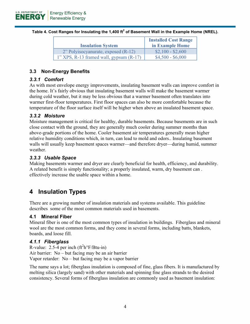
Costs Used Here are $1.02 per therm. ............................................................................................... 3 Table 4. Cost Ranges for Insulating the 1,400 ft2 of Basement Wall in the Example Home (NREL). . 4 Table 5. Overview of Floor Insulation Required by Current Codes (2009 IECC Table 402.1.1) ........ 32
Unless otherwise noted, all tables were created by the CARB team

vii
Acronyms and Abbreviations
AHJ Authority Having Jurisdiction
AFUE Annual Fuel Utilization Efficiency
ASHRAE American Society of Heating, Refrigeration, and Air Conditioning Engineers
CARB Consortium for Advanced Residential Buildings
CAZ Combustion Appliance Zone
CMU Concrete Masonry Unit
DOE U.S. Department of Energy
EIA Energy Information Administration
EPS Expanded polystyrene
HVAC Heating, Ventilation, and Air Conditioning
ICC International Code Council
ICF Insulated Concrete Form(s)
IECC International Energy Conservation Code
IRC International Residential Code
NREL National Renewable Energy Laboratory
Polyiso Polyisocyanurate
R-value Resistance to thermal transfer [ft2hr°F/Btu]
SPF Spray Polyurethane Foam
U-value Thermal conductance [Btu/ft2hr°F]
XPS Extruded polystyrene

viii
Foreword
This guideline is intended to describe good practices for insulating basements in new and existing homes, and to be a practical resource for building contractors, designers, and homeowners. There is limited discussion here about heat transfer principles, moisture transfer, and related research in basement assemblies. Several references are provided for readers looking for more detailed or technical information on related topics. Several insulation systems are described in this guideline. This is not an exhaustive list; rather it is a short list of systems that work well, comply with current codes, and can be practically implemented by builders and contractors. The insulation systems described here meet—but may not exceed—many current code requirements (2009 IECC, 2009 IRC). Builders of high-performance homes are encouraged to modify these systems to achieve higher thermal performance, as desired.
Acknowledgements
This Guide is the product of a collaborative effort. The authors would like to acknowledge the funding and support of the U.S. Department of Energy’s (DOE) Building America program and related work from several Building America teams. Special thanks to David Lee of the U.S. Department of Energy and Ren Anderson and Cheryn Engebrecht of the National Renewable Energy Laboratory.

ix
Progression Summary
These flowcharts are provided as a very high-level overview of the planning and selection process for basement insulation systems. Note that these guidelines—and certainly these charts—are not exhaustive. Many references are provided that discuss several viable basement systems as well as achieving thermal performance well above code minimums.
New Construction
Address site drainage and plan for water/moisture management.
Assess risks posed by insects and other pests.
Design and install safe combustion systems in the home. • Sealed combustion equipment is strongly recommended. • Include carbon monoxide detectors.
Determine code requirements. See Section 2 for a brief discussion of national codes; refer to local codes and/or AHJ.
Consider exterior rigid insulation (Section 7.2), insulated concrete forms (Section 7.3.1), or prefabricated panels (Section 7.3.2).
Install systems per code requirements and manufacturer specifications.
Select Insulation system: Do site and pest control limitations allow for exterior insulation or panelized systems?
If not, consider interior insulation systems (Section 7.1).
Verify systems are installed properly and other systems (such as drainage systems, combustion appliances, etc.) are operating safely.

x
Existing Homes
If not, work with qualified engineers and/or contractors to repair foundation as necessary.
Assess foundation integrity: Is the foundation structurally sound?
If not, address venting and/or replace combustion appliances. Sealed combustion appliances and carbon monoxide detectors are strongly recommended for all homes.
Assess combustion safety: Are combustion appliances operating safely?
If so, address these problems before proceeding. Consider pest management when selecting an insulation system.
Assess pest problem: Are there termites or other pest problems in the home? Is there a risk of such problems in the region?
If not, consider sealing and insulating at the basement ceiling. See Section 7.4 If so, implement moisture management measures before proceeding.
Evaluate moisture management at the site: If moisture problems exist, can measures be installed to prevent ground water and storm water intrusion into the basement and foundation wall system?
Install insulation system: Select an appropriate foundation wall insulation system. Reference Sections 7.1 - 7.3
Verify systems are installed properly and ensure that combustion appliances are operating safely after improvements have been made.

1
1 Introduction
Because basements are largely below grade, and because winter ground temperatures are often warmer than winter air temperatures, the potential for heat loss from a basement is smaller than from above-grade portions of a home’s envelope. As late as the early 2000’s, it was common to see regional codes in northern U.S. climates that required no basement insulation at all (Figure 1). Codes have changed for good reasons. While insulation levels below grade need not be as high as those of above-grade walls, insulating basements is critical to achieve energy and comfort goals of high-performance homes. This document is intended to describe good practices for insulating basements in new and existing homes. Some background information is given on assessing moisture issues, moisture management, insects, heat transfer principles, and costs and benefits of basement insulation. Most of the document, however, focuses on several viable basement insulation systems. This is by no means an exhaustive list; rather it is a short list of systems that can work well, comply with current codes, and can be practically implemented by builders and contractors. References are provided for more information on critical topics such as moisture management and insect/pest control. References are also provided for those willing to achieve thermal performance much higher than minimum code requirements.
2 Building Codes
In current building codes (2009 IECC and 2009 IRC), the warmest climate zones (1 and 2) do not require basement wall insulation. These areas are dominated by cooling loads, not heating loads, and ground-coupling of basements (without insulation) can reduce cooling loads in some situations. Table 1 shows two values for minimum insulation R-values in climate zones 3 and higher: the first is R-value of continuous insulation (such as foam boards) and the second is cavity insulation R-value (e.g. fiberglass batts in a framed wall). The last column in Table 1 shows the equivalent U-value for a basement assembly; this is typically used when non-conventional insulation systems are employed.
Table 1. Basement Wall Insulation Requirements from 2009 IECC (Tables 402.1.1, 402.1.3) and 2009 IRC (Tables N1102.1, N1102.1.2).
Minimum Basement Wall Insulation Climate
Zone Insul. R-value [ft2-hr-°F/Btu]
Wall U-value [Btu/ft2-hr-°F]
1-2 0 0.360 3 5/13 * 0.091
4-5 10/13 * 0.059 6-8 15/19 * 0.050
* The value before the slash represents continuous insulation; the value after the slash represents cavity insulation in a framed wall.
Minnesota has implemented some significant alterations to the foundation insulation section of the IRC (Minnesota 2009). The additional language does not alter the required R-values

2
substantially, but building scientists worked with regulators to attempt two key changes to basement insulation requirements:
• In new construction, require exterior foundation insulation
• When foam must be installed on the interior (in existing homes), provide clear moisture control strategies.
As is often the case with development of regulations, compromises were made, and exterior foundation insulation is not mandated in new construction. The code does, however, recognize that simply specifying an R-value is not sufficient guidance for below-grade insulation. Because of moisture and thermal dynamics below grade, selecting a durable system that manages moisture as well as heat transfer requires some thought and care.
Figure 1. A basement without ceiling or wall insulation in a home built in 2001 near Chicago. Until
recently, basement insulation was not required by many local codes, even in cold climates.
3 Cost and Performance
3.1 Energy Savings While the energy savings of basement wall insulation are less than that of above-grade wall insulation (for the same R-values), the effects of insulating an uninsulated foundation wall can be dramatic. To demonstrate the energy savings, the authors referred to modeling used to develop the “Retrofitting Home Analysis Dashboard” (CARB 2010). This demonstration showed the effects of various retrofit measures on a typical 1970’s home in various climates.

3
To demonstrate basement insulation savings in a cold climate, a 3-bedroom, 1,647-sq.ft. home was modeled in Chicago. The modeled home had relatively poor insulation—typical of the 1970’s—and old HVAC equipment with an AFUE of 76%. In the base case model, the full basement had no insulation (quite common in the Chicago area until recently). For details on the homes, see CARB’s Retrofitting America: A 1970s Home Energy Efficiency Analysis. Table 2 shows the substantial energy savings that can be achieved by adding continuous insulation to R-10 and R-15 levels.
Table 2. Modeling Results for Adding Basement Insulation to Reference Home in Chicago. Gas Costs Used Here are $1.02 per therm (EIA 2005).
Table 3. Modeling Results for Adding Basement Insulation to Reference Home in Baltimore. Gas Costs Used Here are $1.02 per therm.
3.2 Costs As with all building systems, costs can vary tremendously by region and even within regions. The costs also vary dramatically with the type of insulation system used. Reasonable cost ranges for several basement insulation systems have been compiled by the National Renewable Energy Laboratory (NREL 2011). Table 4 shows cost examples for two insulation systems. More information on these and other systems is presented in section 7 below; example costs are presented here to demonstrate relative benefits of costs and savings.
Basement Annual GasInsulation Use [therms] [therms] Cost
None 1753 0 $0First floor: R-13 batts
1636 117 $120
Foundation Wall: R-10 Continuous
1487 266 $272
Foundation Wall: R-15 Continuous
1452 301 $308
Annual Savings
Basement Annual GasInsulation Use [therms] [therms] Cost
None 1373 0 $0First floor: R-13 batts
1287 86 $88
Foundation Wall: R-10 Continuous
1172 201 $206
Foundation Wall: R-15 Continuous
1146 227 $232
Annual Savings
4
Table 4. Cost Ranges for Insulating the 1,400 ft2 of Basement Wall in the Example Home (NREL).
Insulation System Installed Cost Range
in Example Home 2” Polyisocyanurate, exposed (R-12) $2,100 - $2,600
1” XPS, R-13 framed wall, gypsum (R-17) $4,500 - $6,000
3.3 Non-Energy Benefits 3.3.1 Comfort As with most envelope energy improvements, insulating basement walls can improve comfort in the home. It’s fairly obvious that insulating basement walls will make the basement warmer during cold weather, but it may be less obvious that a warmer basement often translates into warmer first-floor temperatures. First floor spaces can also be more comfortable because the temperature of the floor surface itself will be higher when above an insulated basement space.
3.3.2 Moisture Moisture management is critical for healthy, durable basements. Because basements are in such close contact with the ground, they are generally much cooler during summer months than above-grade portions of the home. Cooler basement air temperatures generally mean higher relative humidity conditions which, in turn, can lead to mold and odors.. Insulating basement walls will usually keep basement spaces warmer—and therefore dryer—during humid, summer weather.
3.3.3 Usable Space Making basements warmer and dryer are clearly beneficial for health, efficiency, and durability. A related benefit is simply functionality; a properly insulated, warm, dry basement can . effectively increase the usable space within a home.
4 Insulation Types
There are a growing number of insulation materials and systems available. This guideline describes some of the most common materials used in basements.
4.1 Mineral Fiber Mineral fiber is one of the most common types of insulation in buildings. Fiberglass and mineral wool are the most common forms, and they come in several forms, including batts, blankets, boards, and loose fill.
4.1.1 Fiberglass R-value: 2.5-4 per inch (ft2h°F/Btu-in) Air barrier: No – but facing may be an air barrier Vapor retarder: No – but facing may be a vapor barrier
The name says a lot; fiberglass insulation is composed of fine, glass fibers. It is manufactured by melting silica (largely sand) with other materials and spinning fine glass strands to the desired consistency. Several forms of fiberglass insulation are commonly used as basement insulation:

5
• Batts are strips of fiberglass sized to fit within framing cavities, typically at 16 or 24 in. on center (i.e. batts are approximately 15 or 23 in. wide). Batt thicknesses are typically in line with framing depth (e.g. R-19 fiberglass batts fit in 2x6 wall cavities with little compression). Batts are available with a variety of facings, including kraft paper, polymer vapor barriers, and “unfaced”.
• Blankets refer to wider sheets of fiberglass (typically 4 ft wide) with typical thicknesses of 3-6 in. (R-11 to R-19). Blankets are nearly always faced with either polypropylene or foil—often perforated—and are attached directly to the foundation walls.
• Rigid boards of fiberglass are available from some manufacturers for use primarily on the outside of foundation walls. The intended function of these boards is twofold: insulation and improved drainage near the basement wall. These boards are typically 1-2 in. thick and are not faced.
• Blown or sprayed fiberglass comes in several forms. Loose, blown fiberglass is commonly used in attics; in basements, insulation can be sprayed against foundation walls (typically within a frame). Some spray fiberglass contains binders that hold the material in place, while other fiberglass systems are sprayed within netting (sometimes called “blown-in batt” or “blown-in blanket”).
4.1.2 Mineral Wool R-value: 3-4 per inch (ft2h°F/Btu-in) Air barrier: No – depends on facing Vapor retarder: No – depends on facing
Mineral wool is similar to fiberglass in many respects. Mineral wool is manufactured from basalt or other minerals often in combination with slag, a byproduct from several industrial processes. Like fiberglass, mineral wool is available in batts and rigid (and semi-rigid) boards; unlike fiberglass, mineral wool is rarely manufactured with a facing.
4.2 Foam Boards There are three primary types of rigid foam boards used for building insulation; the use and properties are different enough to consider them separately. All products are typically available in 2x8 ft or 4x8 ft sheets with thicknesses of 0.5 – 2 in.
4.2.1 Expanded Polystyrene (EPS) R-value: 3.8-4.4 per inch (ft2h°F/Btu-in) Air barrier: Yes Vapor retarder: Typically Class III (2-6 Perm-inch, ASHRAE 1997)
Expanded polystyrene (EPS) is a white foam board sometimes called “bead board” because of its composition; it appears to be made up of many small, compacted beads. Of the three rigid foam products, EPS has the lowest R-value (per inch) and the highest moisture vapor permeability. EPS can be used outside or inside foundation walls. When used inside, the higher permeability can be valuable in some applications. EPS is also used in several insulated concrete form systems (ICFs).

6
EPS is generally provided without a facing, though polymer or foil facings are sometimes available. As with most foams, EPS cannot be left exposed indoors. Most codes call for a thermal barrier (e.g. 2009 IRC Section R316.4).
4.2.2 Extruded Polystyrene (XPS) R-value: 5 per inch (ft2h°F/Btu-in) Air barrier: Yes Vapor retarder: Typically Class II (1.2 Perm-inch, ASHRAE 1997)
While chemically similar to EPS, extruded polystyrene (XPS) results in slightly higher thermal resistance and lower moisture vapor permeability. While EPS is nearly always white, XPS is usually colored; blue, pink, and green XPS boards are available from different manufacturers. XPS is commonly used outside of foundation walls, inside foundation walls, and in some ICF systems. As with EPS, typically XPS cannot be left exposed indoors.
4.2.3 Polyisocyanurate (Polyiso) R-value: 6-7 per inch (ft2h°F/Btu-in) Air barrier: Yes Vapor retarder: Depends on facing; typically Class I
Unlike EPS and XPS, polyisocyanurate foam boards are always faced on both sides with polymer and/or foil. This facing makes polyiso boards impervious to moisture vapor diffusion—a consideration when deciding on an insulation strategy. When installed on the inside of a foundation wall, some foil-faced polyiso insulations can be left exposed (testing has found them to be a Class 1, Class A interior finish system ICC 2006, NER-681).
Figure 2. EPS insulation on a basement wall. Insulation will eventually be covered with drywall.

7
4.3 Polyurethane Spray Foam R-value: 3-4 (low-density), 6-7 (high-density) per inch (ft2h°F/Btu-in.) Air barrier: Yes Vapor retarder: Typically Class III for low-density (15-40 perm-inch) and Class II for high-
density (1 perm-in.)
As with rigid foam boards, it’s useful to consider spray foam in two fairly distinct categories: high-density (or closed-cell) and low-density (or open-cell). As the numbers above suggest, low-density foam is relatively permeable to water vapor. While the vapor permeability may be appropriate for basement wall assemblies, the open cells make the foam somewhat like a sponge. Open-cell foam can absorb and hold water within the insulation, so this product is not appropriate where it may be exposed to bulk water. High-density spray foam is much less permeable to vapor, and the closed cells in the insulation prevent liquid water from passing through as well.
Some “medium-density” spray foams are also available; as one might expect, physical properties of medium-density spray foams are between those of the high- and low- density foams discussed here.
As with rigid foam boards, spray foam can typically not be left exposed. A thermal barrier (such as ½” gypsum board) is usually required.
Figure 3. Foil-faced polyisocyanurate installed inside a basement wall
4.4 Cellulose R-value: 3-4 per inch (ft2h°F/Btu-in) Air barrier: No Vapor retarder: No

8
Cellulose insulation—often made from recycled newspapers—is appealing to some because of its recycled content and low embodied energy. While additives to cellulose limit risks from pests and fire, the insulation loses its effectiveness if it becomes wet (as does fiberglass and open-cell spray polyurethane foam). As basement wall systems must be more moisture resistant than above-grade assemblies, cellulose is generally not recommended to insulate basement walls if it is going to be in direct contact with the concrete.
In some instances, blown cellulose can be used effectively in first floor framing. Appropriate netting is installed beneath the floor joists, and cellulose is blown to fill the joist cavities.
5 Assessing Basement and Foundation Conditions
For an insulation system to provide proper thermal resistance while not impacting health, safety, or building durability, it’s critical that several factors be assessed quite carefully. In new construction, these factors are much more straightforward to assess and plan for; in existing homes, assessment (and management) can be more difficult. Four key factors are:
• Structural integrity
• Water and moisture management
• Insect and pest management
• Combustion safety.
5.1 Structural Integrity A discussion of structural performance of foundations is beyond the scope of this document. However, adding insulation to an existing foundation that has structural issues can mask the problem or, in some cases, even exacerbate a problem. See these resources for assessing the condition of older basement foundations (TX ASCE 2002, CMHC 2011d).
Basements are essentially holes in the ground; as such, they are susceptible to filling with water. Water management is critical in providing for overall durability and healthy basement conditions. Water issues can be related to rain or stormwater run-off, ground water intrusion, movement of moist air, water vapor movement, or bulk water leaks from inside the basement (e.g. plumbing leaks). Insulating basement walls without adequately addressing moisture management can simply mask problems down the road; in some cases, insulation can trap water in assemblies and cause more severe problems.
Moisture management MUST be addressed before insulating a basement. At the time of this writing, a separate Building America guideline document is in development focusing on foundation moisture management. These resources may also provide useful information in assessing and addressing basement moisture issues (Lstiburek 2002, King 1999, CMHC 2011c, CMHC 2011a).
5.2 Insect and Pest Management Insect problems vary tremendously from region to region and even locally within regions. Termites eat wood, and precautions should be taken for any wood assemblies located near grade.

9
Termites do not eat most insulation products (such as foams and fiberglass), but they can often tunnel through these materials to reach food sources in the building.
When termites tunnel through insulation they are generally not visible. Some foundation insulation strategies rely on “vision strips”, basically, gaps in insulation that force pests to come out into the open. Vision strips do not stop insects, but they make them noticeable. If termites are present, a regular inspection of vision strips will discover mud tunnels. When pests are identified, other pest control measures must be taken.
Figure 4. Termite shield detail for interior foundation insulation
Figure 5. Termite shield detail for exterior foundation insulation (e.g. XPS, fiberglass board) where
above-grade frame walls also have exterior rigid insulation. Approximate scale: 1-½ in. = 1 ft.
Vision strips have a significant drawback: they require gaps in the insulation. These gaps are generally near grade where insulation is most important thermally (because of the larger temperature differentials). Where possible, the authors recommend termite shields rather than

10
gaps in insulation. Termite shields also do not necessarily prevent infestation, but they force insects to leave the insulation assembly. As with vision strips, tunnels around the shields can be noticed and proper control steps taken. Examples of termite shield details are shown in Figure 4 and 5 above.
There are also insulation products available (including some XPS foam boards) with pesticides incorporated into them. Manufacturers of these products often recommend termite shields or similar barriers be used as well.
Termites can represent a substantial durability risk in some areas. Where risks are present, the details presented in section 7 should be altered to include termite shields or other measures. If effective pest management cannot be incorporated effectively into foundation insulation systems, other strategies should be considered (such as insulating beneath the first floor). Some more rigorous resources for pest management in these resources (Caromdy 1991, NC State 2007, Mallis 1997, MSU 2000, CMHC 2011b, USGBC 2008).
5.3 Combustion Safety Finally, basements are often home to combustion appliances (boilers, furnaces, water heaters, etc.). Atmospherically-vented appliances—where exhaust gases are drawn up a flue by natural convection—require substantial amounts of outdoor air to be drawn into the basement (or into the home overall). This outdoor air represents a significant energy liability, and air sealing of a building envelope is as important—if not more important—than installing additional insulation, but could potentially cause problems with proper combustion in atmospherically vented appliances.
The insulation details discussed below emphasize air sealing. While poured concrete walls do not leak air, the sills and rim joists are notorious air leakage areas. Before and after sealing and insulating a basement, ensure that combustion appliances are operating appropriately and safely. The best way to avoid combustion problems is to install sealed-combustion equipment (these appliances have their own, dedicated outside air inlets). If equipment other than sealed-combustion equipment is present in a home, have a qualified contractor assess combustion safety. These resources may be helpful (BPI 2005, ACCA 2011).
6 Where to Insulate?
6.1 Foundation Walls or First Floor? One of the first questions to answer when determining a basement insulation strategy is: Will insulation be on the basement walls or beneath the first floor?
Most often, insulating the basement walls—and possibly the slab—results in better performance. Bringing the basement within the conditioned space will obviously keep the basement warmer during the winter. In the summer, a conditioned basement will usually be dryer than the alternative. A warmer, dryer basement can have much more value as a functional, usable space.
In extremely cold climates, insulating the basement walls may be critical to keep temperatures in the basement above freezing (if there are any mechanicals or plumbing in the basement). Similarly, if heating equipment is located in the basement (e.g. boiler, water heater, ducts, etc.), the heat losses from this equipment provides some space conditioning to the cold basement. It is

11
true that with efficient HVAC systems these losses should be small, but the “losses” may still provide most of a basement’s heating requirements.
During summer months, because the ground is generally cooler than the air within the home, connecting the basement to the conditioned space will reduce the cooling load. It’s true that good basement wall insulation will limit this cooling effect, but even a home with a well-insulated basement will generally require less air conditioning energy than the same home with insulation beneath the first floor.
While insulating beneath the first floor may result in lower performance overall, there are some scenarios where this strategy is still chosen. Reasons for this include:
• Water management. If moisture management strategies do not keep the basement consistently dry (e.g. if the area is prone to seasonal flooding), insulating at the first floor may be the most viable option.
• Combustion safety. If upgrading natural-draft equipment in the basement (to sealed combustion equipment) is not in the project scope, it may be more practical to insulate and seal at the first floor. In this way, air sealing strategies and providing combustion air are not potentially at odds.
• Cost. While insulating the basement walls generally results in better performance, this strategy is often more expensive. Some choose to insulate at the floor purely for cost reasons.
6.2 Inside or Outside Foundation Walls? Insulating on the outside of a foundation wall is usually only a practical option in new construction. Most retrofit strategies involve insulation on the inside of the foundation walls unless major excavation is necessary for foundation repair or site water management..
In most cases, insulating on the outside can result in better moisture management of the foundation assembly (Yost 2002, Goldberg and Huelman 2001), but there are challenges with protecting the insulation at and above grade. These challenges lead many designers and builders of new homes to choose interior basement insulation. Examples of both strategies—as well as challenges and limitations of each—are discussed in section 7 below.
6.3 Full Wall or Top Portion? As described above, less insulation is required for basement walls because the ground temperature is less severe than outdoor winter air temperatures. However, the top portions of basement walls are in contact with outdoor air. During winter conditions, the first few feet of earth below grade also become much colder than earth at the bottom of a typical basement (6-8 feet below grade).
These higher temperature differentials near the tops of basement walls lead some to insulate only the upper portions of walls. In some cases, this may be appropriate; insulating the top four feet of a foundation wall can cut insulation costs in half. As discussed more in section 7.1, leaving the lower half of the wall exposed may allow moisture to move in and out of the wall assembly, which typically leads to drier, more durable conditions.
However, insulating only the top half of a wall is not always appropriate. Certainly in walk-out basements, the entire foundation wall will be exposed to winter air temperatures. In hollow, concrete masonry unit (CMU) walls (as opposed to monolithic concrete), convective air currents

12
within the CMU cavities may negate insulation benefits unless the whole wall is insulated. Especially in cold climates, winter ground temperatures will be substantially colder than interior temperatures; even for monolithic walls, insulating the entire wall will reduce heat loss. In some cases, exposed foundation walls can lead to condensation during humid weather. Finally, full-height insulation may be required by codes (2009 IECC, 2009 IRC) if the prescriptive compliance path is followed.
6.4 Beneath Basement Slab? For slabs of insulated basements below grade level, codes generally do not require sub-slab insulation. In most regions, ground temperatures several feet below grade stay near the average annual air temperature of the region. With these lower temperature differentials, potential for heat loss is much lower than in other parts of the envelope. In some cases, such as in walk-out basements, slabs will be subject to much colder temperatures and good slab insulation becomes very important. Regardless of the basement depth, basement slabs that incorporate radiant heating require more rigorous sub-slab insulation.
In addition to reducing heat loss from basement slabs, sub-slab insulation may also improve comfort by raising the basement floor temperature during winter months. During the summer, a warmer basement floor may reduce risk of condensation and moisture problems.
The most common, effective sub-slab insulation material is rigid XPS foam. One or two inches of XPS (R-5 to R-10) may be used in colder climates when striving for higher-performance envelopes. If the slab is near grade or incorporates radiant heating, twice this amount of insulation is recommended. In the next section, some of the details show XPS insulation incorporated beneath the basement slab.
7 Insulation Strategies and Details
This section describes several basic, recommended insulation systems – including advantages, drawbacks, and limitations. This is certainly not an exhaustive list. Designers or contractors reaching for higher levels of energy efficiency may want to explore altering these systems (or chose different systems) to improve thermal performance. 7.1 Insulation on Interior of Foundation Walls In existing homes, interior basement insulation is often the only practical option. Even in new construction, challenges with protecting insulation at grade and above—as well as integrating the extra dimensions of exterior insulation—lead some builders to install interior insulation. Building America researchers have found that the best interior basement wall insulation strategies have several key features:
• Insulation is directly in contact with the basement wall; i.e., there is no channel for air movement between the insulation and the concrete.
• The assembly is air sealed so that basement air (and the moisture in it) cannot move into the insulation assembly.
• No moisture-sensitive materials are in contact with the concrete walls or floor (this is often addressed by building codes).

13
• The insulation system is somewhat permeable to water vapor.
In 2002-2003, CARB performed side-by-side tests of several insulation systems in the basement of a new home in northern Illinois (Figure 6, Aldrich et al. 2006, Zuluaga et al. 2004). Researchers at BSC performed similar evaluations (Ueno 2006, Ueno 2007). Not surprisingly, studies found that systems where insulation was directly against the wall (e.g. rigid foam glued or fastened directly to concrete) had much better thermal performance than systems where air can move between the insulation and concrete (such as framed walls where, by necessity, framing stands out from the concrete).
Studies also found that insulation systems were dryer when water vapor was allowed to move between the basement and the concrete wall. Sseveral systems with continuous Class I vapor barriers were more likely to experience higher moisture levels (even liquid water) against the concrete.
Figure 6. CARB tested several insulation systems side-by-side in a basement near Chicago, IL
Based on these studies—and on more practical factors such as cost—the systems below are commonly recommended where insulation is located inside of walls.
7.1.1 Exposed, Foil-Faced, Polyisocyanurate Board Most residential building codes require foam insulation to be covered with a thermal barrier (2009 IRC, Section R316.4). The most common type of barrier is drywall. However, attaching drywall over foam is costly, especially when finishing the basement is not part of the project scope. At least one manufacturer of foil-faced, polyisocyanurate board insulation has a product that is allowed to remain exposed per an International Code Council Evaluation Services report

14
(ICC 2006, NER-681). In many jurisdictions, this product can be left exposed against basement walls without drywall or additional thermal barrier.
Figure 7 shows a section of this system, and an example of a completed installation is shown in Figure 8. Insulation may either be fastened with construction adhesive or with mechanical fasteners into the concrete. Polyisocyanurate has an R-value of 6-7 per inch (ft2hr°F/Btu-in). Typically one inch is installed to meet R-5 requirements; 1.5-2 inches are installed to reach R-10, and 2.5-3 inches are installed to reach R-15.
For best performance, the polyiso boards should be completely sealed to each other and to the concrete wall; there should be no avenue for air movement between the basement and the space between the foam and the foundation wall. Insulation seams can be sealed with foil or polypropylene tape; caulk or foam should be used at the top and bottom edges of insulation.
One potential drawback of this system is that foil-faced polyisocyanurate is a class I vapor retarder. The research discussed above showed that allowing some moisture vapor to move between the foundation wall and the basement generally leads to dryer systems. Research has found that leaving a small gap (approximately six inches) of exposed foundation wall between the insulation and basement floor can result in dryer conditions in the foundation wall (Aldrich and Zuluaga 2006).
If such a gap cannot be maintained, it is even more important to seal the foam to the wall as the space between the foam and foundation wall may often be saturated with moisture. For CMU foundation walls, insulation extending to the floor may be necessary to prevent convective currents within the blocks from compromising the system’s thermal integrity.
As with most systems described here, spray foam is an excellent option to seal and insulate the sill and band joists area. Many codes allow for this small area of foam to be left exposed in these locations (2009 IRC, Section R316.5.11).

15
Figure 7. Foil-faced polyisocyanurate foam boards tightly adhered to the inside of foundation wall. Approximate scale: ¾ in. = 1 ft.

16
7.1.2 Polystyrene Board with Drywall Unfaced polystyrene foam—both expanded (EPS) and extruded (XPS)—are more permeable to water vapor than foil-faced polyisocyanurate. They cannot, however, be left exposed without a thermal barrier (2009 IRC Section R316.4); the most common such barrier is ½-in. drywall.
Of these two foams (EPS and XPS), XPS is more commonly used, simply because it has a higher R-value (R-5 per in. rather than R-4). To meet R-5, R-10, and R-15 code requirements, one, two, and three inches of foam are required respectively.
As with the polyisocyanurate foam insulation systems, XPS foam can be attached to the wall with construction adhesive or with mechanical fasteners. Seams in the foam should be taped, and the top and bottom edges should be sealed to the concrete with caulk or foam. In one method of mechanical attachment (shown in Figure 10), fasteners are attached through 1x furring strips. This furring then serves as a base for attaching drywall with screws.
Using these furring strips against irregular walls can be more challenging, as concrete surfaces are not always smooth. The drywall may follow any irregularities in furring or wall shape. While wires can be run in the gap between the drywall and the foam, electrical boxes (when installed) must be recessed and cut into the foam. To overcome these challenges, some chose to install a more conventional frame wall inside of the rigid foam (detail shown in Figure 11). Framing cavities can be filled with batts or other appropriate cavity insulation. With the addition of frame cavity insulation, less rigid foam may be required to meet target R-values. For example, one inch of XPS in conjunction with a 2x4 wood-framed wall (20% framing factor) and R-13 fiberglass batts results in an effective R-value of approximately 15 ft2hr°F/Btu (U-value of 0.065 Btu/ft2hr°F).
In very cold climates, however, care should be taken to limit condensation risks on the surface of the foam. A frame cavity R-value much higher than the foam R-value could lead to foam surface temperatures below dew point temperatures under extreme conditions. Designers may chose foam R-values higher than fiberglass R-values, or simply forego framing cavity insulation entirely.

17
Figure 8. Foil-faced polyisocyanurate boards mechanically attached to basement wall through
furring strips. Board seams were sealed with foil tape, and all edges (top, bottom, window) were sealed with caulk or foam.
Figure 9. XPS installed inside basement walls. Drywall will be installed to provide the required
thermal barrier.

18
Figure 10. XPS foam insulation adhered to the inside of the foundation wall. Drywall – required as
a thermal barrier - is attached to 1x4 in. furring strips. Approximate scale: ¾ in.=1 ft.

19
Figure 11. XPS attached to the inside of the basement wall. The drywall thermal barrier is attached to a 2x4 frame wall installed inside the foam insulation. Frame cavities can be filled with batts or
loose fill insulation to improve R-value of the assembly. Approximate scale: ¾ in.=1 ft.

20
7.1.3 Spray Foam with Framing and Drywall Sprayed polyurethane foam can provide excellent air sealing and thermal resistance in many envelope systems. The chief drawback to the product is often cost; it is usually more expensive to install than rigid foam boards. Like unfaced foam boards, spray foam cannot be left exposed; it must be covered with a thermal barrier. While spray foam can be effective in many types of foundation walls, with very irregular walls (such as stone foundations), spray foam is one of the only options for excellent thermal and moisture performance.
Research discussed previously has shown that wall systems that allow some water vapor transmission between the foundation wall and the interior of the basement can result in more durable, drier basement wall systems. Of the two basic types of spray foam available (high-density, closed-cell and low-density, open-cell), only the open-cell foam allows significant vapor transmission. Open-cell spray foam, however, can also absorb and retain water (up to 40% by volume). This characteristic makes it rather unforgiving in the event of bulk water intrusion or severe condensation events. For this reason, closed-cell foam is recommended for most foundation wall applications.
A recommended spray-foam system for a poured-concrete or block wall is shown in Figure 12. Framing is installed at least one or two inches within the foundation wall to allow for a continuous layer of foam. Drywall (which provides the required thermal barrier) is attached to 2x4 framing in this detail. As with the XPS system discussed above, it’s possible to use a hybrid system with spray foam directly against the foundation wall and cavity insulation within the framing. It may also be practical to use 2x3 framing or steel framing in some applications.
A spray-foam system for use with a more irregular wall is shown in Figure 13. The concept of this system is very much the same: closed-cell spray foam is applied directly to the foundation wall, and the frame wall supports the drywall (required as a thermal barrier); however, Figure 13 shows some different moisture management features. In many existing homes, it is not practical to excavate around foundation walls to install proper footing drainage and water proofing. In such cases, it is sometimes possible to install drains around the inner perimeter of the foundation wall to help manage water. These drains should run to daylight or to a pumped sump. It is still important to manage rain water (proper gutters, grade sloped away from house, etc.), and a vapor barrier on the floor of the basement is still necessary. For more information on this type of system see (Lstiburek 2010).
In some situations where a significant water is expected through or near a basement wall, a separate drainage layer is installed between the spray foam and foundation wall (Goldberg). With irregular walls, sometimes this is simply a sheet of polyethylene. In other cases, especially where moisture needs to be drained along a block or poured concrete wall, a ribbed or “dimple” drainage mat is used to create a discrete drainage channel. While closed-cell spray foam is quite impermeable to moisture, in some cases this dedicated layer provides more rigorous drainage.
It bears repeating that proper moisture management is critical for basements. These sections show examples of moisture control strategies that may or may not be appropriate for a specific home. Proper water management should be assessed on a case-by-case basis.

21
Figure 12. Closed-cell spray foam on the inside of a foundation wall. Drywall is attached to a 2x4
frame wall; cavities may be filled with additional insulation as desired. Approximate scale: ¾ in.=1 ft.

22
Figure 13. Spray foam and a framed wall installed inside an older foundation. Addressing water management is key for all systems. The interior, perimeter drain shown here may be appropriate
in some cases. Approximate scale: ¾ in.=1 ft.

23
7.1.4 Added Challenges with Masonry Block Walls While the systems above can often work for both poured and masonry block walls, masonry walls have features that allow less room for error with respect to moisture management. Most of these issues are related to the hollow cores of masonry walls; these cores allow for air convection (and therefore moisture movement) vertically through the wall system.
In cold climates, surface temperatures at the upper portion of the wall can stay below dew point temperatures for extended periods of time. This can cause a build-up of moisture in the block cavities, and with hollow cores, it’s possible for liquid water to collect and pool within the foundation walls. Exterior insulation (discussed below) largely addresses these concerns, but with interior insulation, drainage of the wall system (such as systems similar to those in Figure 13) can be even more critical for long-term viability of the system (Goldberg 2006).
7.2 Insulation Outside of Block or Poured Concrete Walls XPS foam, rigid fiberglass, and mineral wool boards are the most common materials for insulating the exterior of foundation walls. Fiberglass and mineral wool boards are also marketed as drainage devices—routing water directly to the footing drain. None of these materials retains water, so long-term thermal properties will not be significantly affected by moisture.
Rigid fiberglass and mineral wool boards have thermal resistance of approximately R-4 per inch (ft2hr°F/Btu-in). To achieve the same R-value, thickness of these insulations must be approximately 25% greater than XPS insulation (R-5 per inch).
In most cases, insulation on the exterior of basement walls can result in drier foundation assemblies and basement conditions (Lstiburek, 2002). The key challenges or caveats for exterior insulation systems are:
• Usually only practical for new construction
• Protecting the insulation at and above grade
• Insect and pest management
• Transitions between foundation insulation and above-grade walls
• Achieving higher R-values can be more difficult than with interior insulation (though a combination of both interior and exterior insulation is possible).
One common—though unacceptable—solution to protecting insulation at grade is simply to insulate below-grade sections of the foundation wall (see Figure 14). In this scenario, the un-insulated portion of the foundation wall (at grade and above) is exposed to the coldest temperatures. Insulating the top portion of the wall is by far the most critical for thermal performance; insulating only below-grade portions of the wall is ineffective in stopping heat transfer.

24
Figure 14. Exterior fiberglass insulation on this new home was cut to terminate below-grade after
backfill. The inside of the wall showed significant condensation—and even ice—during cold winter conditions.
Figure 15. Exterior XPS basement insulation installed completely to above-grade walls

25
Figure 16. Rolled, fiberglass sheets are installed to protect exterior XPS at and above grade
Insulation must be extended to the top of the foundation wall to provide a seamless thermal barrier in conjunction with the above-grade walls, and foundation insulation at and above grade level must be protected with a rigid, durable material. Possible materials include stucco, fiber-cement boards, fiberglass panels, vinyl sheets, aluminum coil stock, or even pressure-treated plywood (Holladay 2003).
Another potentially tricky detail is integrating the extra dimension of the foundation insulation into the above-grade walls. There are many solutions to this; two are presented here. In Figure 17, the above-grade walls also incorporate rigid, exterior insulation. In this case, there is usually not much difference between the two planes. If above-grade walls do not have exterior insulation, there must be a curb, flashing, or transition that protects the insulation, manages drainage well, and is aesthetically acceptable. One solution is presented in Figure 18.
When considering any external foundation insulation strategy, it is critical to consider insects and pest management. While termites and other pests do not eat foam, they can easily tunnel through foam to reach wooden building components. Many insect management strategies incorporate “vision strips” (gaps in insulation exposing concrete) and termite shields that do not necessarily stop termites, but the devices will force bugs out of the building assembly where their presence can be noticed. See section 5.2 above for examples of termite shield details and references to more information..

26
Figure 17. Exterior foundation insulation (e.g. XPS, fiberglass board) where above-grade frame
walls also have exterior rigid insulation. Approximate scale: ¾ in.=1 ft.

27
Figure 18. Rigid, exterior foundation insulation (e.g. XPS, fiberglass board) where above-grade
frame walls do not include exterior, rigid insulation. Approximate scale: ¾ in.=1 ft.

28
7.3 Other Foundation Wall Insulation Systems The insulation systems discussed above present effective ways to insulate conventional foundations. For new construction, there are several systems that incorporate insulation into the structural foundation system. The two systems discussed here are insulated concrete forms (ICFs) and pre-cast foundation systems.
7.3.1 Insulated Concrete Forms (ICFs) While there are many manufacturers and variations of ICFs, the core concept is consistent: instead of using wooden or metal foundation forms, concrete is poured into insulating forms which remain in place after the concrete has cured. The insulation material is most often polystyrene, either EPS or XPS. Many ICF systems consist of hollow, polystyrene blocks that are tied together with polymer spacers. Courses of blocks are stacked together depending on the building plan; as the blocks are stacked, rebar or other structural supports are installed as needed. As the ICF foam generally cannot be left exposed on the inside of basement walls, many ICF systems include ties or strips to which interior and exterior finishing can be attached. Instead of “sandwiching” concrete between foam layers, a related system sandwiches insulation between layers of concrete (Figure 21). This approach can solve many concerns such as thermal barrier, some moisture issues, and possibly pest management.
Figure 19. Insulated concrete forms before pour

29
Figure 20. ICF walls
Figure 21. Insulation in the middle of poured concrete walls

30
7.3.2 Pre-Cast Foundations Precast concrete foundations have a significant presence in several regional markets, in particular in the northeast and in the Midwest. Not surprisingly, both these regions are dominated by full basement foundations in residential construction, and they have robust pre-cast concrete industries. Very simply, pre-cast foundations are factory-produced concrete panels designed for a specific project, shipped to a job site, and set by a crane and set crew. A very simple foundation could consist of as few as four panels; larger, more complicated foundations require more. The simplest panels are monolithic reinforced concrete slabs, while more sophisticated panels can be pre-insulated “sandwich” panels (with a layer of rigid insulation encapsulated between two withes of concrete), or thin (2” thick) panels with monolithically poured top bond-beams, bottom footers, and evenly spaced concrete ribs. Some of these thin-shell rib systems have integrated insulation. Insulation levels vary, but levels can generally be adjusted to whatever functional level is desired by the builder.
Figure 22. A completed, pre-cast, insulated foundation

31
Figure 23. These pre-cast foundation panels have wood nailing strips over concrete ribs for
attaching drywall. While the panels include insulation, additional spray foam has been added to these walls.
Pre-cast panels are typically set on a compacted crushed stone base with no additional footing needed. A recent code change included in the 2009 IRC prescriptively details the requirements for this application. The crushed stone base is placed and compacted uniformly over the entire foundation area (including slab). The first panel is meticulously located to pre-surveyed points, with the remaining panels worked off of it. Joints between panels are typically treated with two large beads of poly-butyl caulk with come-along bolt connections used to draw panels together followed by a variety of damp/moisture proofing techniques over the entire below grade surface. Pre-cast foundations can be set in a single day, and – with no additional footing requirements – multiple days can be eliminated from the process. Panel bracing is critical prior to backfilling, so installing the floor deck needs to be done with limited at-grade access. The time savings is also a labor savings, but material costs are generally higher. Total installed cost-differentials in locations close to panel plants are typically low and are dependent on local market conditions.
7.4 First Floor Insulation For reasons discussed previously, insulating basement walls (rather than the first floor) results in a dryer, warmer, more comfortable and functional basement. However, there may be times when moisture management strategies cannot be implemented effectively (because of site conditions, budget limitations, etc.). For such situations, air-sealing and insulating at the first floor may be most effective.
32
The first floor plane (between the basement and first floor) generally has many penetrations (plumbing, electrical, ducts, flues, stairs, etc.). Air sealing, therefore, can be much more challenging and time consuming. As discussed above, spray foam provides excellent air sealing and insulating capacity in a single system, and it can certainly be effective in basement ceilings. Spray foam generally cannot, however, be left exposed in the basement; it must be covered by a thermal barrier as in other applications. Installing rigid foam is also possible, but cutting foam to conform with framing and other obstructions can be time-consuming. Except for certain foil-faced polyisocyanurate boards, rigid foam must also be covered with a thermal barrier.
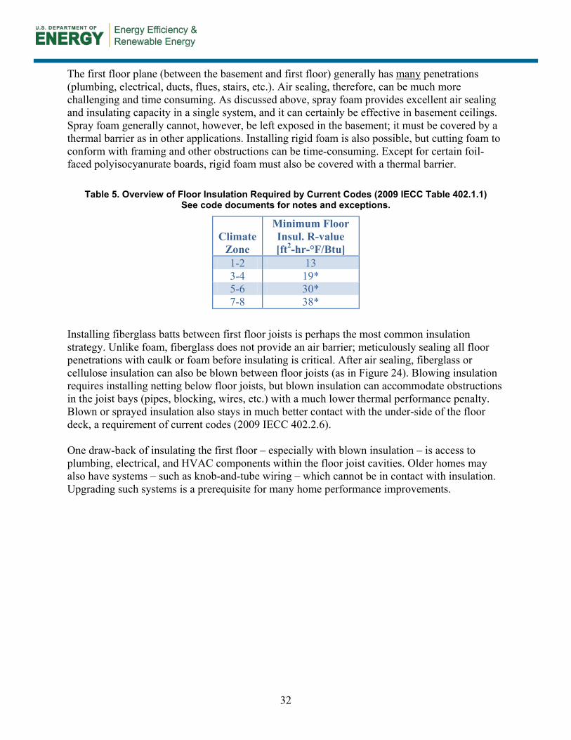
Table 5. Overview of Floor Insulation Required by Current Codes (2009 IECC Table 402.1.1) See code documents for notes and exceptions.
Climate Zone
Minimum Floor Insul. R-value [ft2-hr-°F/Btu]
1-2 13 3-4 19* 5-6 30* 7-8 38*
Installing fiberglass batts between first floor joists is perhaps the most common insulation strategy. Unlike foam, fiberglass does not provide an air barrier; meticulously sealing all floor penetrations with caulk or foam before insulating is critical. After air sealing, fiberglass or cellulose insulation can also be blown between floor joists (as in Figure 24). Blowing insulation requires installing netting below floor joists, but blown insulation can accommodate obstructions in the joist bays (pipes, blocking, wires, etc.) with a much lower thermal performance penalty. Blown or sprayed insulation also stays in much better contact with the under-side of the floor deck, a requirement of current codes (2009 IECC 402.2.6). One draw-back of insulating the first floor – especially with blown insulation – is access to plumbing, electrical, and HVAC components within the floor joist cavities. Older homes may also have systems – such as knob-and-tube wiring – which cannot be in contact with insulation. Upgrading such systems is a prerequisite for many home performance improvements.

33
Figure 24. After air sealing, cellulose was blown into the cavities between the first-floor joists
8 Summary and Additional Information
In the past decade, the building community has become more aware that basement insulation is an important component of a good thermal envelope. Energy codes have reflected this, and research and evaluation efforts have highlighted some of the best systems for long-term thermal and moisture performance. Key guidelines for best-practice basement insulation systems include:
• Always address site moisture concerns, pest issues, structural integrity, and combustion safety first.
• If possible, insulate basement walls rather than the first floor.
• Most basements wall systems are drier when insulation is on the exterior of the foundation wall.
• The top portion of a basement wall has the highest potential for heat loss; insulating only below-grade portions of a wall is not acceptable.
• Insulation should be directly in contact with the foundation wall; there should be no channel for air to move between the insulation and foundation.
• The system should be air-tight so that no air can move through the insulation to the foundation.

34
• Basement wall systems are dryer (overall) when there is some vapor permeability in an interior insulation system. Systems with a Class I vapor retarder can result in very wet conditions at the foundation wall. If vapor-impermeable systems are used, air sealing is even more critical.
• Foam is recommended in many basement insulation systems, but most foam cannot be left exposed. It must be covered with a suitable thermal barrier.
In general, the systems discussed in this document meet requirements of the 2009 IECC and IRC (and likely the requirements in the upcoming 2012 codes). Higher R-value systems are certainly possible and encouraged for high-performance homes. The details presented here can be adjusted to achieve higher R-values. Refer to other Building America publications that are specifically focused on higher R-value assemblies (Smegal and Straube 2010, Straube et al. 2010).

35
References
ACCA. (2011). Existing Residential Building Performance Improvement. Arlington, VA: Air Conditioning Contractors of America. http://www.acca.org/Files/?id=722. Accessed April 25, 2011. Aldrich, R.; Zuluaga, M. (2006). “The Challenges of Basement Insulation.” Home Energy Magazine. ASHRAE. (1997). ASHRAE 1997 Handbook of Fundamentals. Atlanta, GA: American Society of Heating, Refrigeration, and Air Conditioning Engineers. BPI. (2005). Technical Standards for the Building Analyst Professional. Malta, NY: Building Performance Institute. http://www.bpi.org/Web Download/BPI Standards/Building Analyst Professional_2-28-05nNC-newCO.pdf. Accessed April 8, 2011. CARB. (2010). “Retrofitting America: A 1970s Home Energy Efficiency Analysis”. Consortium for Advanced Residential Buildings. http://www.carb-swa.com/articles/homepage/RetrofittingAmerica_1970sHomeAnalysis.pdf. Accessed April 8, 2011. Carmody, J.; Christian, J.; Labs, K.. (1991) “Builder’s Foundation Handbook”. Oak Ridge, TN. Oak Ridge National Laboratory. ORNL/CON-295. http://www.ornl.gov/sci/roofs+walls/foundation/ORNL_CON-295.pdf. Accessed April 16, 2012. CMHC. (2011a). “Avoiding Basement Flooding.” About Your House — General Series. Canada Mortgage and Housing Corporation. http://www.cmhc-schl.gc.ca/en/co/maho/gemare/gemare_002.cfm. Accessed April 25, 2011. CMHC. (2011b). “Dealing with Pests.” About Your House — General Series. Canada Mortgage and Housing Corporation. http://www.cmhc-schl.gc.ca/en/co/reho/reho_008.cfm. Accessed April 25, 2011. CMHC. (2011c). “Renovating your Basement — Moisture Problems.” About Your House — General Series. Canada Mortgage and Housing Corporation. http://www.cmhc-schl.gc.ca/en/co/renoho/refash/refash_012.cfm. Accessed April 25, 2011. CMHC. (2011d). “Renovating your Basement — Structural Issues and Soil Conditions.” About Your House — General Series. Canada Mortgage and Housing Corporation. http://www.cmhc-schl.gc.ca/en/co/renoho/refash/refash_013.cfm. Accessed April 25, 2011. Dow Chemical. (2007). Installation Procedures for Thermax™ Insulations, Exposed Basement Applications. http://msdssearch.dow.com/PublishedLiteratureDOWCOM/dh_0050/0901b80380050a34.pdf?filepath=styrofoam/pdfs/noreg/179-07260.pdf&fromPage=GetDoc. Accessed May 2, 2011.

36
EIA. (2005). “Table US7: Unit Price by Fuels Used.” 2005 Residential Energy Consumption Survey: Energy Consumption and Expenditures Tables. Energy Information Administration. http://www.eia.doe.gov/emeu/recs/recs2005/c&e/summary/pdf/tableus7.pdf. Accessed April 6, 2011. Goldberg, L.F.; Huelman, P. H.. (2001). Cloquet Residential Research Facility: Rim Joist and Foundation Insulation Project Final Report. Minneapolis, MN: University of Minnesota, Building Foundations Research. http://www.buildingfoundation.umn.edu/RimJoist/default.htm. Accessed April 19, 2012. Goldberg, L. (2006). “Proposed Interior Insulation Configuration for Basements with Wet Walls.” Minneapolis, MN: University of Minnesota, Building Foundations Research. http://www.buildingfoundation.umn.edu/WetWallProposal/WetWallProp.htm. Accessed April 19, 2012. Holladay, M. (2003). “Protecting Exterior Foundation Insulation.” Energy Design Update (EDU). vol 23, no. 3. pp. 13-15. ICC. (2006). National Evaluation Services Report NER-681. International Code Council. http://www.icc-es.org/reports/pdf_files/nes/ner681.pdf. Accessed May 2, 2011. IECC. (2009). International Energy Conservation Code. Washington, DC: International Code Council. IRC. (2009). International Residential Code. Washington, DC: International Code Council. King, J.E.; Meyer, G. (1999). “A Builder’s Guide to Residential Foundation Insulation.” Topeka, KS: Energy Programs, Kansas Corporation Commission, 16pp. http://www.engext.ksu.edu/henergy/envelope/builderguide.pdf. Accessed April 25, 2011. Kumaran, M.K.; Lackey, J.C. ; Normandin, N., van Reenen, D.. (2006). “Vapor permeances, air permeances, and water absorption coefficients of building membranes.” Journal of Testing and Evaluation. vol 34. no. 3. http://www.nrc-cnrc.gc.ca/obj/irc/doc/pubs/nrcc46885/nrcc46885.pdf. Accessed May 2, 2011. Lstiburek, J. (2000). Builder’s Guide to Cold Climates. Newtown, CT: Taunton Press. Lstiburek, J. (2002). “Foundations – Moisture Resistant Construction.” BSC RR-0206. Somerville, MA: Building Science Corp., 8pp. http://www.buildingscience.com/documents/reports/rr-0206-foundations-moisture-resistant-construction. Accessed April 25, 2011. Lstiburek, J. (2010). “Rubble Foundations.” ASHRAE Journal. pp. 72-78. Mallis, A. (1997). Handbook of Pest Control: The Behavior, Life History, and Control of Household Pests. Mallis Handbook & Technical Training Co.

37
Minnesota Office of Revisor of Statutes. (2009). Minnesota Administrative Rules Chapter 1322: Residential Energy Code. https://www.revisor.leg.state.mn.us/rules/?id=1322&view=chapter. Accessed April 16, 2012. MSU. (2000). Management of Wood-destroying Pests. Minnesotta State University Pesticide Education Program. MSU Manual E-2047. http://www.pested.msu.edu/Resources/bulletins/E2047.html. Accessed May 17, 2011. NC State. (2007). “Biology and Control of Subterranean Termites.” North Carolina State University Dept. of Entomology. http://www.ces.ncsu.edu/depts/ent/notes/Urban/termites/index.htm. Accessed May 17, 2011. NREL. (2011) “National Residential Efficiency Measures Database: Retrofit Measures for Basement Wall.” National Renewable Energy Laboratory. http://www.nrel.gov/ap/retrofits/measures.cfm?gId=1&ctId=3. Accessed April 29, 2011. Smegal, J.; Straube, J. (2010). Building America Special Research Project: High-R Foundations Case Study Analysis. Building Science Corporation Research Report 1003. http://www.buildingscience.com/documents/reports/rr-1003-building-america-high-r-foundations-case-study-analysis. Accessed May 9, 2011. Straube, J. (2010). High R-value Enclosures for High Performance Residential Buildings in All Climate Zones. Westford, MA.: Building Science Corporation. TX ASCE. (2002). Guidelines for theEvaluation and Repair of Residential Foundations. Austin, TX: Texas Section, American Society for Civil Engineers. http://www.aaronsinspections.com/Foundation%20Repair%20Guidelines%20TXASCE.pdf. Accessed April 25, 2011. Ueno, K.; Townsend, A. (2006). “Field Monitoring of the Hygrothermal Performance of Interior Basement Insulation Systems.” Proceedings of the American Council for an Energy Efficient Economy Summer Study on Energy Efficiency in Buildings. http://www.eceee.org/conference_proceedings/ACEEE_buildings/2006/Panel_1/p1_27/Paper/. Accessed May 9, 2011. Ueno, K.; Schumacher, C.; Straube, J. (2007). “Field Monitoring and Hygrothermal Modeling of Interior Basement Insulation Systems.” Proceedings of Thermal Performance of the Exterior Envelopes of Whole Buildings X International Conference. http://www.ornl.gov/sci/buildings/2010/Session%20PDFs/123_New.pdf. Accessed May 9, 2011. USGBC. (2008). LEED for Homes Reference Guide, First Edition. Washington, DC: U.S. Green Building Council. Yost, N.; Lstiburek, J. (2002). Basement Insulation Systems. Westford, MA: Building Science Corporation. http://www.eere.energy.gov/buildings/building_america/pdfs/db/35017.pdf. Accessed May 2, 2011.

38
Zuluaga, M.; Aldrich, R. ; Griffiths, D. (2004). “Field Performance of Different Basement Insulation Systems.” Proceedings of Performance of the Exterior Envelopes of Whole Buildings IX.

39
Appendix A: Measure Implementation Checklist Based on these guidelines, the checklist below is presented as a potential framework (though not an exhaustive resource) for conducting basement insulating efforts. Stop-Work Form Is the foundation structurally sound?
• Yes – Proceed • No – Work with qualified engineer and/or contractor to repair foundation as needed.
Is electrical properly/safely installed?
• Yes – Proceed • No – Work with qualified electrician to repair as needed.
Are combustion appliances operating safely?
• Yes – Proceed • No – Work with qualified HVAC contractor to obtain proper appliance combustion..
Will air sealing the foundation affect the combustion appliances (depends on whether the combustion air source is from the basement or directly from the outside)?
• Yes – Work with qualified HVAC contractor to provide appropriate combustion make-up air. • No – Proceed
Is there evidence of termites or other pest problems (ants, cockroaches, rodents, etc.) in the home?
• Yes – Work with certified pest control contractor to remediate the problem. • No – Proceed
Are there issues with moisture (bulk or high relative humidity) in the basement?
• Yes – Work with qualified engineer and/or contractor to assess the source(s) of moisture and to take the appropriate corrective action.
• No – Proceed Are there issues with radon in the basement?
• Yes – Work with qualified engineer and/or contractor to implement an appropriate mitigation strategy.
• No – Proceed Foundation Detail Quick Reference The table below provides a quick reference to which foundation detail to consider based upon several building characteristics: foundation material, desired location of insulation, whether or not the basement is being finished or not, and the type of housing construction.

40
Insulation Location Drywall or Thermal Barrier
Required
Construction Type
Interior Exterior Retrofit New Foundation System
x x x Exposed Polyiso on Interior (Figure 7)
x x x x XPS on Interior, Furred out, Drywall (Figure 10)
x x x x XPS on Interior, Framed out, Cavity Insulation, Drywall (Figure 11)
x x x x CCSF on Interior, Framed out, Drywall (Figure 12)
x x x x CCSF on Interior, Framed out, Drywall (Figure 13)
x x Board Insulation on Exterior (Above-and Below-Grade Walls) (Figure 17)
x x Board Insulation on Exterior (no above-grade wall rigid insul) (Figure 18)
x x x x Insulated Concrete Form varies varies x Pre-Cast Foundation Panels

41
Appendix B: Material Specification Air Barrier. Restrict air movement in or out of a material or construction assembly.
Required Code Requirements: ASTM E2178, ASTM E2357 Insulation. Thermal insulating material that can be blown, sprayed, or installed as a batt, blanket, or board.
Relevant Test Methods: ASTM C518, ASTM E84, ASTM E119, ASTM C976 Rigid Foam. Thermal insulating board material.
Required Code Requirements: IRC - foam plastic, complies with NFPA Standards 286 Relevant Test Methods: ASTM C518, ASTM E84, ASTM E119, ASTM C976
Spray Polyurethane Foam. Non-structural thermal insulating material that can be spray applied.
Required Code Requirements: IRC - foam plastic, complies with NFPA Standards 286 Relevant Test Methods: ASTM C518, ASTM E84, ASTM E119, ASTM C976
Vapor Barrier. Restrict movement of moisture through a material or construction assembly.
Required Code Requirements: ASTM E96 (Procedure A): Class I Vapor Retarder: 0.1 perm or less Class II Vapor Retarder: 1.0 perm or less and greater than 0.1 perm Class III Vapor Retarder: 10 perms or less and greater than 1.0 perm

DOE/GO-102012-3716 ▪ October 2012 Printed with a renewable-source ink on paper containing at least 50% wastepaper, including 10% post-consumer waste.