Embed Size (px)
Citation preview

1Ie[uiascOitrtft
tItmmbs
rsporlftif
526 J. Opt. Soc. Am. A/Vol. 25, No. 2 /February 2008 Rodolphe Conan
Mean-square residual error of a wavefront afterpropagation through atmospheric turbulence
and after correction with Zernike polynomials
Rodolphe Conan*
University of Victoria, Engineering Lab Wing B133, P.O. Box 3055 STN CSC, Victoria, British Columbia,Canada V8W 3P6
*Corresponding author: [email protected]
Received October 2, 2007; accepted November 26, 2007;posted December 6, 2007 (Doc. ID 88145); published January 31, 2008
The root-mean-square (rms) of the residual wavefront, after propagation through atmospheric turbulence andcorrected from Zernike polynomials, has been derived for the von Kármán turbulence model. The rms for anylocation in the telescope pupil and the pupil average rms have been calculated. It is shown that the residualrms on the edge of the pupil can be up to 35% larger than the pupil average residual rms. The results areuseful to estimate the required rms stroke of deformable mirror (DM) actuators when they are used as a secondstage of correction either in a tip–tilt, single-DM configuration or in a tip–tilt, two-DM (woofer–tweeter) setup.© 2008 Optical Society of America
OCIS codes: 000.3860, 010.1330, 010.1290, 010.1080.
tttps
2PAIovncmt
sswlt�t
wtpe
Yp
. INTRODUCTIONn the past 25 years, adaptive optics (AO) systems havemerged as a key component of present Large Telescopes1–3], and all future Extremely Large Telescopes [4,5] willse an AO system. The final performance of an AO system
s usually assessed with sophisticated end-to-end models,nd several software packages have been developed foruch a purpose [6,7]. However, one still relies on analyti-al formulas for quickly prototyping an AO system [8].ne of the simplest methods to evaluate AO performance
s to use Zernike polynomials [9] as an ideal representa-ion of the deformable mirror (DM). The statistics of theesidual wavefront phase, the phase after propagationhrough the atmospheric turbulence and from which aew Zernike modes are removed, gives a first estimate ofhe ultimate performance of an AO system.
The use of Zernike polynomials for describing theurbulence-induced phase aberrations is well known [10].n his seminal paper, Noll gives the mean-square error ofhe residual phase derived for the Kolmogorov turbulenceodel. It is also known that the Kolmogorov turbulenceodel is valid for a scale length of a few meters [11,12],
eyond which it becomes inaccurate and other models,uch as the von Kármán model, are preferably used.
In this paper, the statistics of the residual phase is de-ived using the von Kármán model. The mean-square re-idual error is calculated at any location of the telescopeupil and is averaged in the pupil. A thorough comparisonf both quantities is made, showing that the mean-squareesidual error on the rim of the pupil is significantlyarger than the pupil average residual error. This allowsor a more accurate specification of the required stroke ofhe DM actuators. It is also shown that the required DMnteractuator stroke can be deduced from the structureunction of the residual phase.
1084-7529/08/020526-11/$15.00 © 2
In Section 2, the statistics of a plane wave propagatinghrough the atmosphere is reviewed in the framework ofhe von Kármán model. The Zernike polynomials are in-roduced in Section 3, and the statistics of the residualhase are derived in Section 4. The properties of the re-idual phase are discussed in Section 5.
. PHASE STATISTICS OF A PLANE WAVEROPAGATING THROUGH THETMOSPHERE
n atmospheric optics, the turbulence is described basedn the fully developed turbulence model that occurs for aery high Reynolds number �Re�106�. The Reynoldsumber depends on the fluid velocity, typical size, andinematic viscosity. In the framework of this model, Kol-ogorov [13–19] explains the turbulence behavior with
he energy cascade principle.The energy cascade principle states that the energy in-
ide the largest eddies of size L0 is transferred intomaller and smaller eddies up to a minimal size l0, fromhich the energy is flushed by viscous dissipation; L0 and
0 are called the outer and inner turbulence scales, respec-ively. Inside the inertial subrange defined by the domainl0 ,L0�, Kolmogorov shows that the structure function ofhe transverse velocity fluctuations are given by
Dv�r� = Cvr2/3, �1�
here Cv is the structure constant of the velocity fluctua-ions and r is the distance between two measurementoints. Several experiments [20,21] have validated thisquation inside the inertial subrange.
Tatarskii [15,16], based on the works of Obukhov andaglom, has derived the structure function of the tem-erature fluctuations
008 Optical Society of America

wflfb
tmtAt
a
wt
htidr
fF
wtofi
lte
tg
w
S
lttw
w
f
wct
wi
w
Ssst
btsw
Ib
w
T
w
Rodolphe Conan Vol. 25, No. 2 /February 2008 /J. Opt. Soc. Am. A 527
DT�r� = CT2r2/3, l1 � r � L0, �2�
here CT is the structure constant of the temperatureuctuations; l1 and l0 are both length scale related to dif-usion and viscosity, respectively, but in the atmosphereoth have almost the same sizeTatarskii defined another typical distance �z0 at which
he square difference of the temperature mean valueseasured between two positions is equal to the mean of
he square difference of the temperature fluctuations.nd, for the turbulence inside the boundary layer, it es-
ablishes a relation between L0 and �z0,
L0 ��z0
�3/4 , �3�
nd between CT2 and L0,
CT2 = �L0
4/3�dT
dz �2
, �4�
here � is a constant and dT /dz is the vertical tempera-ure gradient.
For large distance r, the condition r�L0 no longerolds. A general law does not exist for the structure func-ion beyond the upper bound of the inertial subrange, butt is expected that after some distance, the average squareifference of the index of refraction fluctuations will satu-ate.
Von Kármán [16] was the first to propose a structureunction that takes into account the saturation regime.or the index of refraction fluctuations, it is given by
Dn�r� =2��7/6�
��Cn
2L02/31 −
22/3
��1/3��2�r
L0�1/3
K1/3�2�r
L0� ,
�5�
here L0 is the parameter representative of the satura-ion and K��r� is the modified Bessel function of the sec-nd kind, or the Macdonald function. When L0 goes to in-nity, then Dn�r�=Cn
2r2/3.There is confusion about the definition of the turbu-
ence outer scale, i.e., between L0 and L0, due to the facthat L0 is very often also called the turbulence outer scaleven though both parameters have different definitions.
The power spectrum of the index of refraction fluctua-ions corresponding to the structure function of Eq. (5) isiven by
Wn�f� =��11/6���7/6�
22/3�8/3��1/3�Cn
2�f2 + f02�−11/6, �6�
here f is the spatial frequency �m−1�, f0=1/L0, and
��11/6���7/6�
22/3�8/3��1/3�= 9.7 � 10−3.
ome authors [22–24] prefer to set f0= �2�L0�−1.For a turbulent atmospheric layer of thickness z
arger than the correlation width of the turbulence fluc-uation and small enough to neglect diffraction propaga-ion effects, the power spectrum of the phase of a planeave crossing the layer is written as [25]
W�f� = k2zWn�f�, �7�
here k=2� /� and � is the wavelength.The covariance of the phase fluctuations is deduced
rom the Wiener–Khintchine theorem
C�r� = F−1�W�f��, �8�
here F−1 is the inverse Fourier transform operator. Be-ause W�f� depends only on the modulus of f, C�r� canhen be rewritten as the Hankel transform of W�f�,
C�r� = 9.7 � 10−3k2zCn22��
0
+�
dff�f2 + f02�−11/6J0�2�rf�,
�9�
here J0�r� is a Bessel function of the first kind. Perform-ng the integration gives
C�r� =��7/6�
�2�5/3��1/3�k2zCn
2f0−5/3�2�rf0�5/6K5/6�2�rf0�,
�10�
here ��7/6� /�2�5/3��1/3�=0.036.The measurements of Cn
2 profiles with instruments likeCIDAR [26–29] or MASS [30–32] show that the atmo-phere is made of the superposition of thin turbulentlabs [33,34]. The covariance of the fluctuations of the in-egrated phase is then
C�r� = 0.036k2� dzCn2�z�f0�z�−5/3�2�rf0�z��5/6
�K5/6�2�rf0�z��. �11�
In Eq. (11), the outer scale depends on the altitude z,ut it is commonly assumed that the covariance of the in-egrated phase, propagated through the whole atmo-phere, can also be represented by the von Kármán modelith a single integrated outer scale:
C�r� = 0.036f0−5/3�2�rf0�5/6K5/6�2�f0r�k2� dzCn
2�z�.
�12�
ntroducing the Fried parameter [35] r0, the covarianceecomes
C�r� =��11/6�
25/6�8/324
5��6/5�5/6
�r0f0�−5/3�2�rf0�5/6K5/6�2�f0r�,
�13�
ith
k2� dzCn2�z� =
5��2/3�
����1/6�24
5��6/5�5/6
r0−5/3. �14�
he power spectrum of the phase is given by
W�f� =��11/6���7/6�
22/3�8/3��1/3��f2 + f0
2�−11/6k2� dzCn2�z�
= 0.0229r0−5/3�f2 + f0
2�−11/6, �15�
ith

at
if
2
T
wKFs
3Tu
w
wdq�
i
w
a
Tfi
a
528 J. Opt. Soc. Am. A/Vol. 25, No. 2 /February 2008 Rodolphe Conan
0.0229 =�2�11/6�
2�11/3 24
5��6
5� .
The phase variance is written
2 = C�0� =
��11/6���5/6�
2�8/3 24
5��6/5�5/6
�r0f0�−5/3,
�16�
nd finally the phase structure function [36–38] is ob-ained:
D�r� = 2� 2 − C�r��
= 2��11/6�
25/6�8/324
5��6/5�5/6
�r0f0�−5/3
� ��5/6�
21/6 − �2�rf0�5/6K5/6�2�rf0� . �17�
One notices that the variance of the phase fluctuationss finite for the von Kármán model, whereas it is infiniteor the Kolmogorov model, as it assumes an infinite L0.
For small distance with respect to the outer scale, i.e.,�rf0�1, the function K5/6�2�rf0� is well approximated by
K5/6�2�rf0� =��− 5/6�
211/6 �2�rf0�5/6 +��5/6�
21/6 �2�rf0�−5/6.
�18�
he structure function then becomes
D�r� = 224
5��6/5�5/6� r
r0�5/3
= 6.88� r
r0�5/3
, �19�
hich corresponds to the phase structure function for theolmogorov model [25], i.e., within the inertial subrange.igure 1 shows both the Kolmogorov and von Kármántructure functions for L0=25 m.
Fig. 1. Phase structure function for L =25 m.
0. ZERNIKE POLYNOMIALShe Zernike polynomials are orthogonal modes on thenit circle. Using Noll [10] notation, they are written
�Zi even� r
R,��=
Zi odd� r
R,��=
Zi� r
R,��=
�n + 1Rnm� r
R�
����2 cos�m��
�2 sin�m��� m � 0
1 m = 0 , �20�
ith
Rnm� r
R� = �s=0
�n−m�/2 �− 1�s�n − s�!
s!��n + m�/2 − s�!��n − m�/2 − s�!� r
R�n−2s
,
�21�
here �r ,�� are the polar coordinates in the pupil of ra-ius R; n and m are the radial degree and azimuthal fre-uency, respectively; and n and m are such that m�n andn−m� is even.
The orthogonality property of the Zernike polynomialss written
� dr �� r
R�Zi� r
R,��Zj� r
R,�� = ij, �22�
here ij is the Kronecker symbol
ij = 1 if i = j
= 0 elsewhere, �23�
nd ��r /R� is the pupil function
�� r
R� =1
�R2 if � r
R� � 1
= 0 elsewhere. �24�
he Fourier transform of the Zernike polynomials is de-ned by
Qi�f,�� =� dr �� r
R�Zi� r
R,��exp�− 2j�f · r�, �25�
nd performing the integration gives
�Qi even�f,��=
Qi odd�f,��=
Qi�f,��= �n + 1
Jn+1�2�fR�
�fR
� ���− 1��n+m�/2jm�2 cos�m��
�− 1��n+m�/2jm�2 sin�m��� m � 0
�− 1�n/2 m = 0 , �26�
wav
4ZTsn
T
AiClt
wEc
d
td
ac
Ad
BTw
wd
f
c
wf
CTtw
Rodolphe Conan Vol. 25, No. 2 /February 2008 /J. Opt. Soc. Am. A 529
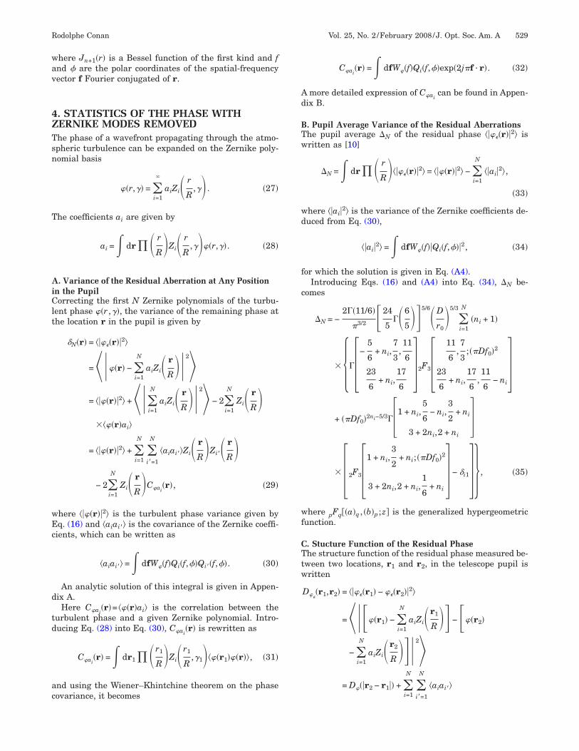
here Jn+1�r� is a Bessel function of the first kind and fnd � are the polar coordinates of the spatial-frequencyector f Fourier conjugated of r.
. STATISTICS OF THE PHASE WITHERNIKE MODES REMOVEDhe phase of a wavefront propagating through the atmo-pheric turbulence can be expanded on the Zernike poly-omial basis
�r,�� = �i=1
�
aiZi� r
R,�� . �27�
he coefficients ai are given by
ai =� dr �� r
R�Zi� r
R,���r,��. �28�
. Variance of the Residual Aberration at Any Positionn the Pupilorrecting the first N Zernike polynomials of the turbu-
ent phase �r ,��, the variance of the remaining phase athe location r in the pupil is given by
N�r� = ����r��2�
=���r� − �i=1
N
aiZi� r
R��2�= ���r��2� +���
i=1
N
aiZi� r
R��2� − 2�i=1
N
Zi� r
R����r�ai�
= ���r��2� + �i=1
N
�i�=1
N
�aiai��Zi� r
R�Zi�� r
R�− 2�
i=1
N
Zi� r
R�Cai�r�, �29�
here ���r��2� is the turbulent phase variance given byq. (16) and �aiai�� is the covariance of the Zernike coeffi-ients, which can be written as
�aiai�� =� dfW�f�Qi�f,��Qi��f,��. �30�
An analytic solution of this integral is given in Appen-ix A.Here Cai
�r�= ��r�ai� is the correlation between theurbulent phase and a given Zernike polynomial. Intro-ucing Eq. (28) into Eq. (30), Cai
�r� is rewritten as
Cai�r� =� dr1 �� r1
R�Zi� r1
R,�1���r1��r��, �31�
nd using the Wiener–Khintchine theorem on the phaseovariance, it becomes
Cai�r� =� dfW�f�Qi�f,��exp�2j�f · r�. �32�
more detailed expression of Caican be found in Appen-
ix B.
. Pupil Average Variance of the Residual Aberrationshe pupil average �N of the residual phase ����r��2� isritten as [10]
�N =� dr �� r
R�����r��2� = ���r��2� − �i=1
N
��ai�2�,
�33�
here ��ai�2� is the variance of the Zernike coefficients de-uced from Eq. (30),
��ai�2� =� dfW�f��Qi�f,���2, �34�
or which the solution is given in Eq. (A4).Introducing Eqs. (16) and (A4) into Eq. (34), �N be-
omes
�N = −2��11/6�
�3/2 24
5��6
5�5/6�D
r0�5/3
�i=1
N
�ni + 1�
� ���−5
6+ ni,
7
3,11
6
23
6+ ni,
17
6�2F3�
11
6,7
3;��Df0�2
23
6+ ni,
17
6,11
6− ni
�+ ��Df0�2ni−5/3��1 + ni,
5
6− ni,
3
2+ ni
3 + 2ni,2 + ni�
� �2F3�1 + ni,3
2+ ni;��Df0�2
3 + 2ni,2 + ni,1
6+ ni
� − i1� , �35�
here pFq��a�q , �b�p ;z� is the generalized hypergeometricunction.
. Stucture Function of the Residual Phasehe structure function of the residual phase measured be-
ween two locations, r1 and r2, in the telescope pupil isritten
D��r1,r2� = ����r1� − ��r2��2�
=���r1� − �i=1
N
aiZi�r1
R � − �r2�
− �i=1
N
aiZi�r2
R ��2�= D��r2 − r1�� + �
i=1
N
�i =1
N
�aiai��
�
TorscZ(
ldo
5T(c
wmFHFpf
trrqaprrt
AIpb
Ft
FmL
530 J. Opt. Soc. Am. A/Vol. 25, No. 2 /February 2008 Rodolphe Conan
�Zi�r1
R � − Zi�r2
R �Zi��r1
R � − Zi��r2
R �− 2�
i=1
N Zi�r1
R � − Zi�r2
R ��Cai�r1� − Cai
�r2��.
�36�
he first term of this expression is the structure functionf the turbulent phase given by Eq. (17). The second termepresents the structure function of the phase recon-tructed with N Zernike polynomials. The third term is aross-coupling term between the turbulent phase and theernike coefficients. The correlation Cai
is given by Eq.32).
Unlike the stationary structure function of the turbu-ent phase, D�
is not a stationary structure function. Itepends on both coordinates r1 and r2 [39,40] and notnly on the modulus of their difference as D��r2−r1��.
. DISCUSSIONhe normalized standard deviation [or root mean square
rms)] of the residual phase at location r in the pupil afterorrection of the first N Zernike polynomials is given by
���,N� = N�r�
�N1/2
= ����r��2�
�dr��r/R�����r��2�1/2
, �37�
here �=r /R, R is the pupil radius, and 2R=D. Pupilaps and the pupil radial cut of ��� ,N� are shown inigs. 2 and 3, respectively, for D=30 m and L0=60 m.ere ��� ,N� does not depend on r0 but varies with D /L0.igure 2 displays the normalized rms when the first eightolynomials, piston to comma, are successively removedrom the turbulent phase. For all the maps, the rms on
ig. 2. (Color online) Map of normalized residual phase rms wheurbulent phase for D=30 m and L =60 m.
0he rim of the pupil is around 1.3 times the pupil averagems. The maps are radially symmetric when, for a givenadial order, all the modes with the same azimuthal fre-uencies have been removed. In Fig. 3, the first 10, 15, 21,nd 28 modes have been removed from the turbulenthase. They correspond to full sets of polynomials withadial orders from 3 to 6 and hence are radially symmet-ic. They all exhibit the same increase of the rms towardhe edge of the pupil.
. Piston and Tip–Tilt Removed Casen closed-loop AO, a DM corrects the turbulence-inducedhase aberrations based on the measurements providedy a wavefront sensor located after the DM. The piston of
rst eight Zernike polynomials are successively removed from the
ig. 3. Radial cuts of residual phase rms for all Zernike polyno-ials from radial order 3 to 6 fully removed and for D=30 m and0=60 m.
n the fi

tiamt
ttDu
t(trricap
daase
BTTtchthm
astml
tfdeh nt n
i(ar
Fc1
Fdd
F(dt
Rodolphe Conan Vol. 25, No. 2 /February 2008 /J. Opt. Soc. Am. A 531
he turbulent phase does not need to be compensated, ast has no effect on the image quality. The tip–tilt is usu-lly not corrected by the DM; instead, a flat mirrorounted on a tip–tilt stage or a gimbal mount supporting
he DM is used.In order to specify the DM stroke required to correct for
he aberrations left after tip–tilt corrections, it is commono use the value of �3
1/2 as the rms stroke needed for theM. This value is correct in average over the pupil butnderestimates the stroke on the pupil edge.Figure 4 shows the residual normalized rms ��1,3� on
he rim of the pupil as a function of D /L0. For D /L0=0infinite outer scale), the residual rms is 1.35 times largerhan the average residual rms. When L0 decreases withespect to the diameter D, the difference between bothms values is reduced, and ��1,3� approaches 1 when Ds smaller than L0. In Fig. 4 the stroke difference, in per-entages, between �N and N�r� for an infinite L0 and for
diameter half of, equal to, and twice L0 is also dis-layed.
ig. 4. Plot of ��1,3� versus D /L0. The percentage of stroke in-rease with respect to �n
1/2 is also superimposed for D /L0=0, 0.5,, and 2.
ig. 5. Radial cuts of ��� ,3� for infinite L0 (solid curve), for aiameter twice the length of L0 (dotted–dashed curve), and for aiameter half the length of L (dashed curve).
0Radial cuts of ��� ,3� for infinite L0 (solid curve), for aiameter twice the length of L0 (dotted–dashed curve),nd for a diameter half the length of L0 (dashed curve)re shown in Fig. 5. When L0 becomes smaller with re-pect to D, the radial profile is smoother from center todge.
. High-Orders Casehe generation of AO systems for the Extremely Largeelescopes will use two DMs in the so-called woofer–weeter scheme [41–43]. One DM, the woofer, will be dedi-ated to the compensation of low-order aberrations. It willave a lot of stroke but a relatively small number of ac-uators. The second DM, the tweeter, will correct theigh-order aberrations. It will need less stroke but manyore actuators.Currently, the DMs with a large number of actuators
re typically based on MEMS (microelectromechanicalystems) and have a notoriously small stroke. Assessinghe right stroke required for these DMs is then of the ut-ost importance to avoid saturating of the actuators and
imiting the performance of the system.Figure 6 shows the variation of the normalized rms on
he edge of pupil ��1,Nn� with Nn= �n+1��n+2� /2 as aunction of the radial order n for infinite L0 (circles), for aiameter twice the length of L0 (diamonds), for a diam-ter equal to the length of L0 (dots), and for a diameteralf the length of L0 (squares). For an infinite outer scale,��1,Nn� does not depend on n and is equal to 1.35 for all. When L0 is finite and decreases with respect to theelescope diameter D, ��1,Nn� decreases. Conversely,��1,Nn� increases with n and converges toward the infi-ite L0 normalized rms.Figure 7 plots �N as a function of the radial order n for
nfinite L0 (circles), for a diameter half the length of L0diamonds), for a diameter equal to the length of L0 (dots),nd for a diameter twice the length of L0 (squares). Theeduction of the pupil average residual variance for the
ig. 6. Plots of ��1,Nn� as a function of n for infinite L0circles), for a diameter twice the length of L0 (diamonds), for aiameter equal to the length of L0 (dots), and for a diameter halfhe length of L (squares).
0
ltsflia
CItta
ebmftaasoi
st
Lw
=ttaisrdsfvwD+
F(at
Fa
532 J. Opt. Soc. Am. A/Vol. 25, No. 2 /February 2008 Rodolphe Conan
ow-order modes is clearly visible. Both Figs. 6 and 7 showhat the outer scale is reducing not only the average re-idual turbulent energy in the telescope pupil but also theuctuations of the residual phase in the pupil. This effect
s exacerbated for the Zernike polynomials of low ordernd for diameters smaller than L0.
. Interactuator Stroken Subsections 5.A and 5.B, we have seen how the map ofhe residual wavefront error can be used to specify the ac-uator stroke of the DMs. Another criterion used to define
DM is the interactuator stroke. It is the stroke differ-
ig. 7. Plots of ��n+1��n+2�/2 as a function of n for infinite L0circles), for a diameter half the length of L0 (diamonds), for a di-meter equal to the length of L0 (dots), and for a diameter twicehe length of L0 (squares).
ig. 8. (Color online) Maps of ���r1 ,r2 ,3� in the case of 61 actuall the actuators and r =r + �d ,0� with d=D /60.
2 1nce between two adjacent actuators, usually measuredy pushing one actuator and pulling the other. An esti-ate of the required interactuator stroke can be deduced
rom the structure function of the residual phase (Subsec-ion 4.C). The evaluation of the structure function with r1nd r2 in Eq. (36) corresponding to the location of the twodjacent actuators gives the variance of the interactuatortroke. Repeating the calculation for all the close couplesf actuators in the pupil allows us to draw a map of thenteractuator stroke variance.
In the following, the normalized rms interactuatortroke ���r1 ,r2 ,N� is used in place of the structure func-ion D�
�r1 ,r2�. It is defined by
���r1,r2,N� = D��r1,r2�
�N1/2
. �38�
ike ��� ,N�, ���r1 ,r2 ,N� does not depend on r0 but variesith D /L0.As an example, Fig. 8 shows ���r1 ,r2 ,N� maps for N
3 and for 61 actuators across the pupil diameter. The in-eractuator rms is computed along the horizontal direc-ion; i.e., r1 is the vector of coordinates of all the actuatorsnd r2=r1+ �d ,0� with d=D /60. The computation of thenteractuator rms along the vertical direction gives theame maps rotated by 90 deg. The four maps (from left toight and top to bottom) correspond to an infinite L0 and aiameter half of, equal to, and twice L0, respectively. It ishown that ���r1 ,r1+ �d ,0� ,3� systematically increasesrom the center to the edge of the pupil, but the peak-to-alley value of the maps decreases when L0 decreasesith respect to the diameter from a 13% difference for/L0=0 to a 0.5% difference for D /L0=2; ���r1 ,r1�d ,0� ,3� also increases when the ratio D /L0 increases,
cross the pupil diameter, where r1 is the vector of coordinates of
tors a
mtts
6Ifsapa
eTce
trddepwtoswo
tD
rtwea
batti1
ACIc
T
Rodolphe Conan Vol. 25, No. 2 /February 2008 /J. Opt. Soc. Am. A 533
eaning that the correlation of the residual phase acrosshe pupil decreases faster when L0 is small with respecto the diameter. This means that the structure functionaturates more rapidly for a larger D /L0 ratio.
. CONCLUSIONn this paper, the statistics of the residual wavefront,rom which Zernike modes have been removed, is de-cribed. In particular, the rms error of the residual phaset any location in the telescope pupil is derived. The com-arison with the rms error averaged over the pupil showssignificant increase on the pupil rim.In the case of the tip–tilt free wavefront, the rms on the
dge is 35% larger than the average rms for an infinite L0.his excess of residual stroke on the pupil edge drops suc-essively to 25%, 16%, and 7% for a pupil diameter half of,qual to, and twice L0, respectively.
For a wavefront corrected from higher Zernike modes,he ratio between the rms on the edge and the averagems is constant (35%) for an infinite L0 whatever the ra-ial order of correction. For a finite L0, the average rmsecreases with the correction order and when the diam-ter increases with respect to L0. The rms ratio betweenupil edge rms and pupil average rms tends toward 1hen the diameter increases with respect to L0. However,
he convergence toward the unit value is slow when therder of correction is large. This shows that the outercale reduces not only the average rms of the residualavefront but also its fluctuations, especially on the rimf the telescope pupil.
This study demonstrates that it is preferable to takehe residual rms on the edge of the pupil as the required
M actuators rms stroke instead of the pupil average h= 0 if �i − i�� is odd,
ms. Considering the pupil average rms only would leado a maximum specification error of 35%. The only casehere the rms on the edge is comparable to the pupil av-rage rms is when the diameter is much smaller than L0nd for the low-order correction.The structure function of the residual wavefront has
een derived too. It can be used to specify the DM inter-ctuator stroke. The computation of the structure func-ion shows that more interactuator stroke is needed onhe rim of the pupil than on the center. The difference ofnteractuator stroke between center and edge ranges from3% for an infinite L0 to 0.5% for a diameter twice L0.
PPENDIX A: ZERNIKE COEFFICIENTSOVARIANCE
ntroducing Eq. (25) into Eq. (30), the Zernike coefficientsovariance becomes
�aiai�� =�2�11/6�
�14/3 24
5��6
5�5/6
r0−5/3f0
−11/3R−2
� ��n + 1��n� + 1��− 1��n+n�−m−m��/2mm�
��0
+� dx
x 1 + � x
�Df0�2−11/6
�Jn+1�x�Jn�+1�x�,
if �i − i�� is even or m = m� = 0
= 0 if �i − i�� is odd. �A1�
he solution to this integral is the sum of two generalized
ypergeometric functions [44]�aiai�� = 1.16�D
r0�5/3
��n + 1��n� + 1��− 1��n+n�−2m�/2mm� � ���3 + n + n�
2,2 +
n + n�
2,1 +
n + n�
2,5
6−
n + n�
2
3 + n + n�,2 + n,2 + n��
� ��Df0�n+n�−5/33F4�
3 + n + n�
2,2 +
n + n�
2,1 +
n + n�
2;��Df0�2
3 + n + n�,2 + n,2 + n�,1
6+
n + n�
2� + ��
n + n�
2−
5
6,7
3,17
6,11
6
n + n�
2+
23
6,n − n�
2+
17
6,n� − n
2+
17
6�
� 3F4�7
3,17
6,11
6;��Df0�2
n + n�
2+
23
6,n − n�
2+
17
6,n� − n
2+
17
6,11
6−
n + n�
2� ,
if �i − i�� is even or m = m� = 0
�A2�
w
a
Wf
l
trii
w
F
ATCIr
w
a
lt
�tti
534 J. Opt. Soc. Am. A/Vol. 25, No. 2 /February 2008 Rodolphe Conan
ith
1.16 =2��11/6�
�3/2 24
5��6
5�5/6
,
nd
�a1, . . . ,ap
b1, . . . ,bq = ��a�
�b� =�n=1
p
��an�
�m=1
q
��bm�
.
ith the above notation, the generalized hypergeometricunctions can be written as
pFq�a�;z
�b� = ��b�
�a��k=0
+�
��a� + k
�b� + k zk
k!. �A3�
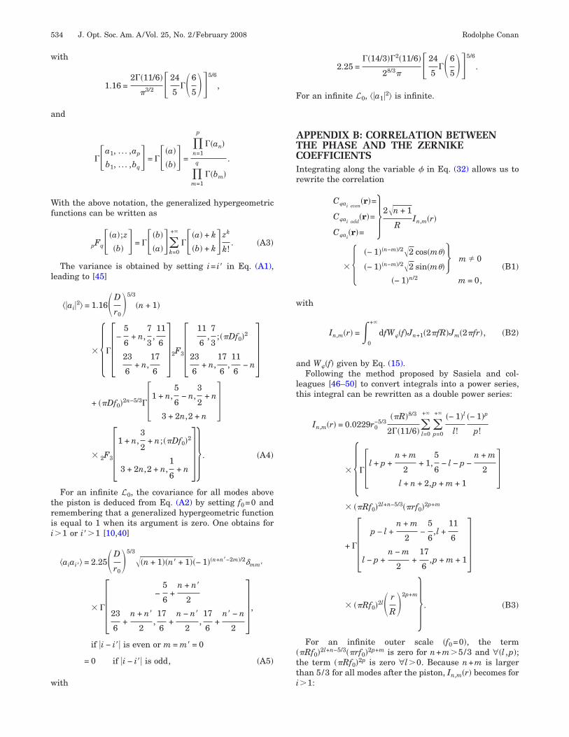
The variance is obtained by setting i= i� in Eq. (A1),eading to [45]
��ai�2� = 1.16�D
r0�5/3
�n + 1�
� ���−5
6+ n,
7
3,11
6
23
6+ n,
17
6�2F3�
11
6,7
3;��Df0�2
23
6+ n,
17
6,11
6− n�
+ ��Df0�2n−5/3��1 + n,5
6− n,
3
2+ n
3 + 2n,2 + n�
� 2F3�1 + n,3
2+ n;��Df0�2
3 + 2n,2 + n,1
6+ n � . �A4�
For an infinite L0, the covariance for all modes abovehe piston is deduced from Eq. (A2) by setting f0=0 andemembering that a generalized hypergeometric functions equal to 1 when its argument is zero. One obtains for�1 or i��1 [10,40]
�aiai�� = 2.25�D
r0�5/3
��n + 1��n� + 1��− 1��n+n�−2m�/2mm�
� �� −5
6+
n + n�
2
23
6+
n + n�
2,17
6+
n − n�
2,17
6+
n� − n
2� ,
if �i − i�� is even or m = m� = 0
= 0 if �i − i�� is odd, �A5�
ith
2.25 =��14/3��2�11/6�
28/3�24
5��6
5�5/6
.
or an infinite L0, ��a1�2� is infinite.
PPENDIX B: CORRELATION BETWEENHE PHASE AND THE ZERNIKEOEFFICIENTS
ntegrating along the variable � in Eq. (32) allows us toewrite the correlation
�Cai even
�r�=
Cai odd�r�=
Cai�r�=
2�n + 1
RIn,m�r�
� ���− 1��n−m�/2�2 cos�m��
�− 1��n−m�/2�2 sin�m��� m � 0
�− 1�n/2 m = 0, �B1�
ith
In,m�r� =�0
+�
dfW�f�Jn+1�2�fR�Jm�2�fr�, �B2�
nd W�f� given by Eq. (15).Following the method proposed by Sasiela and col-
eagues [46–50] to convert integrals into a power series,his integral can be rewritten as a double power series:
In,m�r� = 0.0229r0−5/3
��R�8/3
2��11/6��l=0
+�
�p=0
+� �− 1�l
l!
�− 1�p
p!
� ���l + p +n + m
2+ 1,
5
6− l − p −
n + m
2
l + n + 2,p + m + 1�
� ��Rf0�2l+n−5/3��rf0�2p+m
+ �� p − l +n + m
2−
5
6,l +
11
6
l − p +n − m
2+
17
6,p + m + 1�
� ��Rf0�2l� r
R�2p+m . �B3�
For an infinite outer scale �f0=0�, the term�Rf0�2l+n−5/3��rf0�2p+m is zero for n+m�5/3 and ∀�l ,p�;he term ��Rf0�2p is zero ∀l�0. Because n+m is largerhan 5/3 for all modes after the piston, In,m�r� becomes for�1:

F
KpuFal
w
w
a
H
w
w
w
R
1
Rodolphe Conan Vol. 25, No. 2 /February 2008 /J. Opt. Soc. Am. A 535
In,m�r� = 0.0229r0−5/3
��R�8/3
2 � r
R�m
��n + m
2−
5
6
n − m
2+
17
6,m + 1�
� 2F1�n + m
2−
5
6,m − n
2−
11
6;� r
R�2
m + 1� . �B4�
or f0=0 and i=1, In,m�r� is infinite.Correlation for an infinite outer scale. For the von
ármán model, ����r��2� is easily deduced from the ex-ressions of ����r��2�, �aiai��, and Cai
�r� given for all val-es of i and i� by Eqs. (16), (A2), and (B1), respectively.or the Kolmogorov model, ����r��2�, ��a1�2�, and Ca1
�r�re infinite. It is then necessary to rewrite Eq. (29) as fol-ows:
N�r� = ���r��2�P + �i=1
N
�i�=1+i1
N
�aiai��Zi� r
R�Zi�� r
R�− 2�
i=2
N
Zi� r
R�Cai�r�, �B5�
here ���r��2�P gathered the piston terms with ���r��2�:
���r��2�P = ���r��2� + ��a1�2� − 2Ca1�r� = ��a1
*�2� − 2Ca1
* �r�,
�B6�
ith
��a1*�2� = ��a1�2� − ���r��2�, �B7�
nd
Ca1
* �r� = Ca1�r� − ���r��2�. �B8�
ere ��a1*�2� is given by
��a1*�2� = 2��
0
+�
dffW�f��2J1�2�Rf�
2�Rf 2
− 1�=
4�2�11/6�
�24
5��6
5�5/6�2R
r0�5/3
��0
+� dx
xx−11/3J1
2�x� −x2
4 , �B9�
here x=2�Rf. After the integration step, one obtains
��a1*�2� =
512
2057
�−5
6,7
3�3/2 24
5��6
5�5/6�2R
r0�5/3
= − 1.0324�2R
r0�5/3
, �B10�
here C* �r� is written as
a1Ca1
* �r� = 2��0
+�
dffW�f�2J1�2�Rf�
2�RfJ0�2�rf� − 1
=2
��2�11/6�24
5��6
5�5/6�2R
r0�5/3
��0
+� dx
xx−8/3J1�x�J0� r
Rx� −
x
2 , �B11�
ith x=2�Rf. Performing the integration leads to
Ca1
* �r� =�2�11/6�
28/3�24
5��6
5�5/6�2R
r0�5/3
� �m=0
� �− 1�m
m!�� m −
5
6
17
6− m,1 + m�� r
R�2m
=�2�11/6�
4 24
5��6
5�5/6�2R
r0�5/3
� ��−5
6
17
6�2F1�−
5
6,−
11
6;� r
R�2
1� . �B12�
EFERENCES1. Y. Clenet, M. E. Kasper, N. Ageorges, C. Lidman, T. Fusco,
O. Marco, M. Hartung, D. Mouillet, B. Koehler, G. Rousset,and N. N. Hubin, “NACO performance: status after 2 yearsof operation,” Proc. SPIE 5490, 107–117 (2004).
2. J.-P. Véran, F. Rigaut, J. Stoesz, G. Herriot, and B.Ellerbroek, “Preliminary commissioning results of Altair,”in Science with Adaptive Optics, W. Brandner and M. E.Kasper, eds. (Springer, 2005), pp. 19–25.
3. P. L. Wizinowich, J. Chin, E. Johansson, S. Kellner, R.Lafon, D. Le Mignant, C. Neyman, P. Stomski, D.Summers, R. Sumner, and M. Van Dam, “Adaptive opticsdevelopments at Keck Observatory,” Proc. SPIE 6272,DOI:10.1117/12.672337 (2006).
4. G. Herriot, P. Hickson, B. L. Ellerboek, D. A. Andersen, T.Davidge, D. A. Erickson, I. P. Powell, R. Clare, L. Gilles, C.Boyer, M. Smith, L. Saddlemyer, and J.-P. Véran,“NFIRAOS: TMT narrow field near-infrared facilityadaptive optics,” Proc. SPIE 6272, DOI: 10.1117/12.672337(2006).
5. M. Le Louarn, C. Vérinaud, V. Korkiakoski, N. Hubin, andE. Marchetti, “Adaptive optics simulations for theEuropean Extremely Large Telescope,” Proc. SPIE 6272,DOI: 10.1117/12.670187 (2006).
6. M. C. Britton, “Arroyo,” Proc. SPIE 5497, 290–300 (2004).7. M. Carbillet, C. Vérinaud, B. Femenía, A. Riccardi, and L.
Fini, “Modelling astronomical adaptive optics—I. Thesoftware package CAOS,” Mon. Not. R. Astron. Soc. 356,1263–1275 (2005).
8. L. Jolissaint, J.-P. Véran, and R. Conan, “Analyticalmodeling of adaptive optics: foundations of the phasespatial power spectrum approach,” J. Opt. Soc. Am. A 23,382–394 (2006).
9. M. Born and E. Wolf, Principles of Optics (Pergamon,1980).
0. R. Noll, “Zernike polynomials and atmospheric turbulence,”J. Opt. Soc. Am. 66, 207–211 (1976).

1
1
1
1
1
1
1
1
1
2
2
2
2
2
2
2
2
2
2
3
3
3
3
3
3
3
3
3
3
4
4
4
4
4
4
4
4
4
4
5
536 J. Opt. Soc. Am. A/Vol. 25, No. 2 /February 2008 Rodolphe Conan
1. J. Mariotti and G. D. Benedetto, “Pathlength stability ofsynthetic aperture telescopes: the case of the 25 cmCERGA interferometer,” in Very Large Telescopes, TheirInstrumentation and Programs, M. Ulrich and K. Jear, eds.(International Astronomical Union, 1984), Vol. 79, pp.257–265.
2. F. Martin, R. Conan, A. Tokovinin, A. Ziad, H. Trinquet, J.Borgnino, A. Agabi, and M. Sarazin, “Optical parametersrelevant for high angular resolution at paranal from GSMinstrument and surface layer contribution,” Astron.Astrophys. Suppl. Ser. 144, 39–44 (2000).
3. A. Kolmogorov, “Dissipation of energy in the locallyisotropic turbulence,” Proc. R. Soc. London, Ser. A 434,15–17 (1991).
4. A. Kolmogorov, “The local structure of turbulence inincompressible viscous fluid for very large Reynoldsnumbers,” Proc. R. Soc. London, Ser. A 434, 9–13 (1991).
5. V. Tatarskii, Wave Propagation in a Turbulent Medium(Dover, 1961).
6. V. Tatarskii, The Effects of the Turbulent Atmosphere onWave Propagation (Israel Program for ScientificTranslations, 1971).
7. L. Landau and E. Lifchitz, Mécanique Des Fluides(Editions MIR, 1971).
8. U. Frish, Turbulence: The Legacy of A. N. Kolmogorov(Cambridge U. Press, 1995).
9. M. Lesieur, La Turbulence (Presses Universitaires deGrenoble, 1994).
0. A. Favre, J. Caviglio, and R. Dumas, “Space–timecorrelations and spectra in a turbulent boundary layer,” J.Fluid Mech. 2, 313–342 (1957).
1. A. Favre, J. Caviglio, and R. Dumas, “Further space–timecorrelations of velocity in a turbulent boundary layer,” J.Fluid Mech. 3, 344–356 (1958).
2. R. Lutomirski and H. Yura, “Wave structure function andmutual coherence function of an optical wave in a turbulentatmosphere,” J. Opt. Soc. Am. 61, 482–486 (1971).
3. G. Reinhardt and S. Collins, “Outer-scale effects inturbulence-degraded light-beam spectra,” J. Opt. Soc. Am.62, 1526–1528 (1972).
4. C. Gardner, “Effects of random path fluctuations on theaccuracy of laser ranging systems,” Appl. Opt. 15,2539–2545 (1976).
5. F. Roddier, “The effect of atmospheric turbulence in opticalastronomy,” in Progress in Optics, E. Wolf, ed. (North-Holland, 1981), Vol. XIX, pp. 281–376.
6. G. Ochs, T.-i Wang, R. Lawrence, and S. Clifford,“Refractive-turbulence profiles measured by one-dimensional spatial filtering of scintillations,” Appl. Opt.15, 2504–2510 (1976).
7. R. Avila, J. Vernin, and E. Masciadri, “Whole atmospheric-turbulence profiling with generalized scidar,” Appl. Opt.36, 7898–7905 (1997).
8. R. Avila, J. Vernin, and S. Cuevas, “Turbulence profileswith generalized scidar at San Pedro Màrtir Observatoryand isoplanatism studies,” Publ. Astron. Soc. Pac. 110,1106–1116 (1998).
9. V. Klückers, N. Wooder, T. Nicholls, M. Adcock, I. Munro,and J. Dainty, “Profiling of atmospheric turbulencestrength and velocity using a generalised SCIDARtechnique,” Astron. Astrophys. Suppl. Ser. 130, 141–155(1998).
0. A. Tokovinin and V. Kornilov, “Measuring turbulenceprofile from scintillations of single stars,” in AstronomicalSite Evaluation in the Visible and Radio Range, J. Vernin,
C. Muñóz-Tuñón, and Z. Benkhaldoun, eds. (AstronomicalSociety of the Pacific, 2002), Vol. 266, pp. 104–112.
1. V. Kornilov, A. Tokovinin, O. Voziakova, A. Zaitsev, N.Shatsky, S. Potanin, and M. Sarazin, “MASS: a monitor ofthe vertical turbulence distribution,” Proc. SPIE 4839,837–845 (2003).
2. A. Tokovinin, S. Baumont, and J. Vasquez, “Statistics ofturbulence profile at Cerro Tololo,” Mon. Not. R. Astron.Soc. 340, 52–58 (2003).
3. C. Coulman, J. Vernin, and A. Fuchs, “Optical seeingmechanism of formation of thin turbulent laminae in theatmosphere,” Appl. Opt. 34, 5461–5474 (1995).
4. R. Avila and J. Vernin, “Mechanism of formation ofatmospheric turbulence relevant for optical astronomy,” inInterstellar Turbulence, J. Franco and A. Carramiñna, eds.(Cambridge U. Press, 1998).
5. D. Fried, “Optical resolution through a randomlyinhomogeneous medium for very long and very shortexposures,” J. Opt. Soc. Am. 56, 1372–1379 (1966).
6. A. Consortini and L. Ronchi, “Choice of the model ofatmospheric turbulence,” Appl. Opt. 11, 1205–1211 (1972).
7. R. Fante, “Mutual coherence function and frequencyspectrum of a laser beam propagating through atmosphericturbulence,” J. Opt. Soc. Am. 64, 592–598 (1974).
8. G. Valley, “Long- and short-term Strehl ratios forturbulence with finite inner and outer scales,” Appl. Opt.18, 984–987 (1979).
9. G. Heidbreder, “Image degradation with random wavefronttilt compensation,” IEEE Trans. Antennas Propag. AP-15,90–98 (1967).
0. J. Wang and J. Markey, “Modal compensation ofatmospheric turbulence phase distortion,” J. Opt. Soc. Am.68, 78–87 (1978).
1. P. J. Hampton, R. Conan, C. Bradley, and P. Agathoklis,“Control of a woofer tweeter system of deformable mirrors,”Proc. SPIE 6274, DOI: 10.1117/12.672451 (2006).
2. R. Conan, P. Hampton, C. Bradley, and O. Keskin, “Thewoofer-tweeter experiment,” Proc. SPIE 6272, DOI:10.1117/12.670720 (2006).
3. R. Conan, C. Bradley, P. Hampton, O. Keskin, A. Hilton,and C. Blain, “Distributed modal command for a twodeformable mirror adaptive optics system,” Appl. Opt. 46,4329–4340 (2007).
4. N. Takato and I. Yamaguchi, “Spatial correlation of Zernikephase-expansion coefficients for atmospheric turbulencewith finite outer scale,” J. Opt. Soc. Am. A 12, 958–963(1995).
5. D. Winker, “Effect of a finite outer scale on the Zernikedecomposition of atmospheric optical turbulence,” J. Opt.Soc. Am. A 8, 1568–1573 (1991).
6. R. Sasiela, “Strehl ratios with various types ofanisoplanatism,” J. Opt. Soc. Am. A 9, 1398–1405 (1992).
7. R. Sasiela and J. Shelton, “Transverse spectral filteringand Mellin transform techniques applied to the effect ofouter scale on tilt and tilt anisoplanatism,” J. Opt. Soc. Am.A 10, 646–660 (1993).
8. R. Sasiela and J. Shelton, “Mellin transform methodsapplied to integral evaluation: Taylor series and asymptoticapproximations,” J. Math. Phys. 34, 2572–2617 (1993).
9. R. Sasiela, “Wave-front correction by one or more syntheticbeacons,” J. Opt. Soc. Am. A 11, 379–393 (1994).
0. R. Sasiela, Electromagnetic Wave Propagation inTurbulence: Evaluation and Application of MellinTransforms (Springer-Verlag, 1994).