Embed Size (px)
DESCRIPTION
ME 163 project 2
Citation preview
ME163 Aerodynamics Project 2: Vortex Panel Method Nhan Lac
Abstract
This project shows how to simulate the air flow over the cylinder shape with lift and no lift by using vortex panel method, also, in this project I will use Matlab to calculate the 𝐶! or over the surface. Moreover, I will find the separation points for each case.
Problem Description
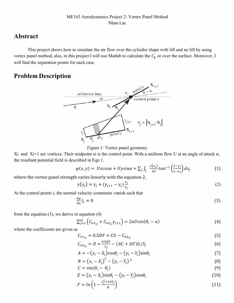
Figure 1: Vortex panel geometry
Xi and Xi+1 are vortices. Their midpoint xi is the control point. With a uniform flow U at an angle of attack 𝛼, the resultant potential field is described in Eqn 1.
𝜑 𝑥,𝑦 = 𝑈𝑥𝑐𝑜𝑠𝛼 + 𝑈𝑦𝑠𝑖𝑛𝛼 + ! !!!!
𝑡𝑎𝑛!! !!!!!!!!
𝑑𝑠!!! (1)
where the vortex panel strength varies linearly with the equation 2, 𝛾 𝑠! = 𝛾! + (𝛾!!! − 𝛾!)
!!!!
(2)
At the control points i, the normal velocity comments vanish such that !"!"|! = 0 (3)
from the equation (3), we derive to equation (4)
𝐶!!!" + 𝐶!!!"𝛾!!! = 2𝜋𝑈𝑠𝑖𝑛 𝜃! − 𝛼 !!!! (4)
where the coefficients are given as 𝐶!!!" = 0.5𝐷𝐹 + 𝐶𝐺 − 𝐶!!!" (5)
𝐶!!!" = 𝐷 + !.!!"!!
− 𝐴𝐶 + 𝐷𝐹 𝐺/𝑆! (6)
𝐴 = − 𝑥! − 𝑋! cos𝜃! − 𝑦! − 𝑌! sin𝜃! (7)
𝐵 = 𝑥! − 𝑋!! − 𝑦! − 𝑌! ! (8)
𝐶 = sin(𝜃! − 𝜃!) (9) 𝐸 = 𝑥! − 𝑋! sin𝜃! − 𝑦! − 𝑌! cos𝜃! (10)
𝐹 = 𝑙𝑛 1−!!!!!!!!!
(11)
𝐺 = 𝑡𝑎𝑛!! !!!!!!!!
(12)
𝑃 = 𝑥! − 𝑋! sin(𝜃! − 2𝜃!) + 𝑦! − 𝑌! cos(𝜃! − 2𝜃!) (13) 𝑄 = 𝑥! − 𝑋! sin(𝜃! − 2𝜃!)− 𝑦! − 𝑌! cos(𝜃! − 2𝜃!) (14)
Kutta condition requires the vortices strength at the trailing edge to be zero: 𝛾!! + 𝛾!!!! = 0 (15)
and 𝑉! is calculated by the following formula 𝑉! = cos 𝜃! − 𝛼 + (𝐶!!!"
!!!! 𝛾!! + 𝐶!!!"𝛾!!!
! ) 𝑖 = 1,2,… ,𝑚 (16) and we come up with the next equation for 𝐶!
𝐶!" = 1− 𝑉!! (17) After I plot the 𝐶! distribution, I am able to figure out the lift and drag acting on the body. The velocities obtained 𝑉! are also used to find separation points according to Twaities' criteria:
𝐾 = !.!"!!!(!!!!") 𝑈!! 𝜉 𝑑𝜉 = −0.09 !
! (18)
where 𝑈! is the external velocity of the ow which is the same as 𝑉!from Eqn (16). The integration starts from stagnation points, which are very close to 0.
To calculate the value of 𝑉! and 𝐶!, the inputs are a set of cylinder array, the number of the vortex panels which are 32, 64 and 128, and the Kutta condition angle 𝜃. Using the vortex panel method, I can get the values of V from the equation (16), and pressure coefficient distribution 𝐶! on the cylinder which are corresponding with set of array x and y. After that, I use those values as inputs to plot 𝐶! and the angle 𝜃 as semiology to find the separation points.
Flow around a cylinder: no-lift
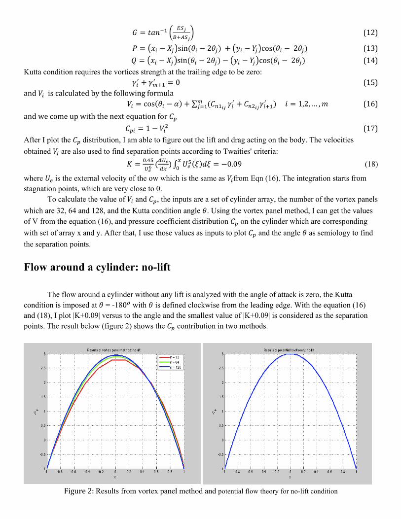
The flow around a cylinder without any lift is analyzed with the angle of attack is zero, the Kutta condition is imposed at 𝜃 = -180! with 𝜃 is defined clockwise from the leading edge. With the equation (16) and (18), I plot |K+0.09| versus to the angle and the smallest value of |K+0.09| is considered as the separation points. The result below (figure 2) shows the 𝐶! contribution in two methods.
Figure 2: Results from vortex panel method and potential flow theory for no-lift condition

And from equation (18) and the data 𝑉! from the previous calculation, we can find the separation points base on the smallest values of |K+0.09| of each partial that easy to see on the figure 3. We can see that the separation points occur at ±102.60, which are very close to ±103.10. Therefore, the separation angles 𝜃!are ±103.10 as upper and lower sides.
Figure 3: Separation points for no-lift condition
Flow around a cylinder: lifting
This is the same with no-lift part above but with 𝜃 = -150! while everything else is the same. The results are showed in the figure 4 and 5.
Figure 4: Results from vortex panel method and potential flow theory for lift condition
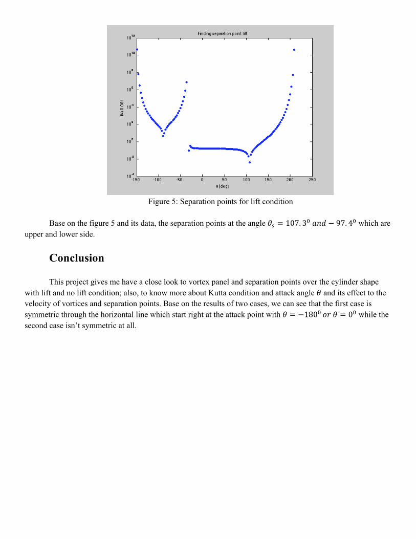
Figure 5: Separation points for lift condition
Base on the figure 5 and its data, the separation points at the angle 𝜃! = 107. 3! 𝑎𝑛𝑑 − 97. 4! which are
upper and lower side.
Conclusion This project gives me have a close look to vortex panel and separation points over the cylinder shape
with lift and no lift condition; also, to know more about Kutta condition and attack angle 𝜃 and its effect to the velocity of vortices and separation points. Base on the results of two cases, we can see that the first case is symmetric through the horizontal line which start right at the attack point with 𝜃 = −180! 𝑜𝑟 𝜃 = 0! while the second case isn’t symmetric at all.