Embed Size (px)
Citation preview

1
ME EN 7960 – Precision Machine Design – Fundamentals of Errors 2-1
Fundamentals of Errors
ME EN 7960 – Precision Machine DesignTopic 2
ME EN 7960 – Precision Machine Design – Fundamentals of Errors 2-2
Accuracy, Repeatability, and Resolution

2
ME EN 7960 – Precision Machine Design – Fundamentals of Errors 2-3
Accuracy
• Accuracy is the ability to tell the truth or:– The maximum translational or rotational error between any two
points in the machine's work volume– Linear, planar, and volumetric accuracy can all be defined for a
machine
• Note: mechanical accuracy is far more costly than repeatability
ME EN 7960 – Precision Machine Design – Fundamentals of Errors 2-4
Repeatability
• Repeatability (precision) is the ability to tell the same story over and over again or:– The error between a number of successive attempts to move the
machine to the same position– Repeatability is often considered to be the most important
parameter of a computer controlled machine (or sensor)– Often the intent is to map the errors and then compensate for
them
• Minimize static friction, backlash, and thermal variants to get better repeatability

3
ME EN 7960 – Precision Machine Design – Fundamentals of Errors 2-5
Resolution
• Resolution is how detailed your story is– Resolution is the larger of the smallest programmable step or:– The smallest mechanical step the machine can make during
point to point motion– Resolution gives a lower bound on the repeatability
• Minimize static friction and use higher resolution feedback to get better resolution
ME EN 7960 – Precision Machine Design – Fundamentals of Errors 2-6
What is the importance of errors?
• The trajectory of the tool relative to the work piece directly determines the dimensions of all features machined
• No machine tool monitors the tool trajectory directly. Instead, the tool trajectory is monitored indirectly by monitoring the position of the moving components (axes)
• Any deviation of any moving component will imprinted onto the work piece, thereby reducing the part accuracy

4
ME EN 7960 – Precision Machine Design – Fundamentals of Errors 2-7
Imprinting Form Errors
Case 1: Perfectly straight z-axis bearings create a perfectly cylindrical part
ME EN 7960 – Precision Machine Design – Fundamentals of Errors 2-8
Imprinting Form Errors (contd.)
Case 2: The straightness errors of the z-axis bearings are transferred onto the part

5
ME EN 7960 – Precision Machine Design – Fundamentals of Errors 2-9
Performance Limiting Criteria
• Accuracy and Repeatability are limited by:– Geometric errors of all components– Kinematic errors– Load induced errors– Thermal errors– Dynamic errors– Calibration errors– Computational errors
• Resolution is limited by– Quality of sensors– Quality of control system– Friction (stick and slip effect)– Backlash
ME EN 7960 – Precision Machine Design – Fundamentals of Errors 2-10
Geometric Errors• Errors in the form of individual machine components:
– Component straightness error due to machining errors– Component straightness error due to gravity loading
• Surface finish effects
• Quasi-static accuracy of surfaces moving relative to each other (e.g., linear or rotary motion axes):– Linear motion axis:
• Pitch• Roll• Yaw• Straightness (2 components)• Linear displacement

6
ME EN 7960 – Precision Machine Design – Fundamentals of Errors 2-11
Geometric Error - Gravity
ME EN 7960 – Precision Machine Design – Fundamentals of Errors 2-12
Geometric Errors - Roll
vertical
lateral

7
ME EN 7960 – Precision Machine Design – Fundamentals of Errors 2-13
Geometric Errors - Pitch
vertical
lateral
ME EN 7960 – Precision Machine Design – Fundamentals of Errors 2-14
Geometric Errors - Yaw
vertical
lateral

8
ME EN 7960 – Precision Machine Design – Fundamentals of Errors 2-15
Other Errors
• Kinematic Errors– Errors in an axis's trajectory that are caused by misaligned or
improperly sized components• Orthogonality between axes• Parallelism between axes• Error motions in a closed kinematic chain
• External load induced errors:– Errors due to deformation of components:
• Gravity load induced errors• Cutting/probing force induced errors• Axis acceleration load induced errors
ME EN 7960 – Precision Machine Design – Fundamentals of Errors 2-16
Kinematic Error - Orthogonality Between Axes
γ⋅=Δ bz

9
ME EN 7960 – Precision Machine Design – Fundamentals of Errors 2-17
Geometric Error – Load Induced
ME EN 7960 – Precision Machine Design – Fundamentals of Errors 2-18
Thermal Errors• Mean temperature other than 68 °F (20 °C)
– Gradients in environment's temperature– Errors caused by thermal expansion of elements:
• External heat sources:– Mean temperature of the room– Sun shining through the window onto the machine– Nearby machine's hot air vent– Overhead lights– Operator's body heat
• Internal heat sources:– Motors– Bearings– Machining process– Pumps– Expansion of compressed fluids– Coolant
10
ME EN 7960 – Precision Machine Design – Fundamentals of Errors 2-19
Dynamic Errors
• Errors caused by vibration or control processes:– Vibration:
• External environment (usually through the ground)• Cutting process• Rotating masses
– Control system:• Algorithm type (e.g., PID, adaptive, etc.)• Stick-slip friction• Varying mass• Varying stiffness
– Switching amplifiers• Servo loop frequency excites a natural mode of the machine
ME EN 7960 – Precision Machine Design – Fundamentals of Errors 2-20
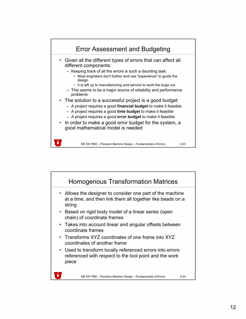
Dynamic Errors

11
ME EN 7960 – Precision Machine Design – Fundamentals of Errors 2-21
Calibration Errors
• Errors associated with sensors:– Intrinsic accuracy– Interpolation– Mounting errors:
• Position• Mounting stress
– Calibration (error associated with the mastering process)
ME EN 7960 – Precision Machine Design – Fundamentals of Errors 2-22
Additional Errors• Computational errors:
– Error introduced in the analysis algorithms– Rounding off errors due to hardware
• Additional sources of error (often very difficult to model):– Humidity– Loose joints– Dirt
• Variations in supply systems:– Electricity– Fluid pressure– Operator inattention– Fluid supply cleanliness
• Operators (“52-2” factor)
12
ME EN 7960 – Precision Machine Design – Fundamentals of Errors 2-23
Error Assessment and Budgeting• Given all the different types of errors that can affect all
different components:– Keeping track of all the errors is such a daunting task:
• Most engineers don't bother and use "experience" to guide the design
• It is left up to manufacturing and service to work the bugs out– This seems to be a major source of reliability and performance
problems• The solution to a successful project is a good budget:
– A project requires a good financial budget to make it feasible– A project requires a good time budget to make it feasible– A project requires a good error budget to make it feasible
• In order to make a good error budget for the system, a good mathematical model is needed
ME EN 7960 – Precision Machine Design – Fundamentals of Errors 2-24
Homogenous Transformation Matrices
• Allows the designer to consider one part of the machine at a time, and then link them all together like beads on a string
• Based on rigid body model of a linear series (open chain) of coordinate frames
• Takes into account linear and angular offsets between coordinate frames
• Transforms XYZ coordinates of one frame into XYZ coordinates of another frame
• Used to transform locally referenced errors into errors referenced with respect to the tool point and the work piece

13
ME EN 7960 – Precision Machine Design – Fundamentals of Errors 2-25
Homogenous Transformation Matrices (contd.)
• Coordinate frames are placed at bearings, joints, and areas where other parameters are lumped
• Closed chains (e.g. a five point bearing mount) need to be modeled with the generation of constraint equations
Source: Alexander Slocum, Precision Machine Design
ME EN 7960 – Precision Machine Design – Fundamentals of Errors 2-26
Structure of HTM’s
⎥⎥⎥⎥
⎦
⎤
⎢⎢⎢⎢
⎣
⎡
=
1000zkzkykx
yjzjyjx
xiziyix
T POOOPOOOPOOO
Rn

14
ME EN 7960 – Precision Machine Design – Fundamentals of Errors 2-27
Structure of HTM’s (contd.)
• The first three columns are the direction cosines (unit vectors i, j, k).– They represent the orientation of the Xn, Yn, and Zn axes with
respect to an adjacent coordinate frame
• The last column is the position of the rigid body's coordinate system's origin with respect to the reference frame
• The pre-superscript represents the reference frame in which you want the result to be represented
• The post-subscript represents the reference frame from which you are transferring:
ME EN 7960 – Precision Machine Design – Fundamentals of Errors 2-28
Structure of HTM’s (contd.)
• The equivalent coordinates of a point in a reference frame n, in a reference frame R are:
Equivalent coordinates of a point in reference frame n,
in reference frame R
⎥⎥⎥⎥
⎦
⎤
⎢⎢⎢⎢
⎣
⎡
=
⎥⎥⎥⎥
⎦
⎤
⎢⎢⎢⎢
⎣
⎡
11n
n
n
TR
R
R
ZYX
RZYX
n
HTM that describes the transformation of reference
frame n into reference frame R
Equivalent coordinates of a point in reference frame n,
in reference frame R

15
ME EN 7960 – Precision Machine Design – Fundamentals of Errors 2-29
Example: Translation in X
• The coordinate system X1Y1Z1 is shifted in X by an amount a:
XR
YR
ZR
X1
Y1
Z1
a
Source: Alexander Slocum, Precision Machine Design
ME EN 7960 – Precision Machine Design – Fundamentals of Errors 2-30
HTM of Translation in x
⎥⎥⎥⎥
⎦
⎤
⎢⎢⎢⎢
⎣
⎡
=
100001000010
001
111
a
XYZZYXT

16
ME EN 7960 – Precision Machine Design – Fundamentals of Errors 2-31
Example: Rotation about X-Axis
• the X1Y1Z1 coordinate system is rotated by an amount θXabout the X axis:
XR = X1
YR
ZR
Y1
Z1
θx
θx
ME EN 7960 – Precision Machine Design – Fundamentals of Errors 2-32
HTM of Rotation about X
⎥⎥⎥⎥
⎦
⎤
⎢⎢⎢⎢
⎣
⎡−
=
10000cossin00sincos00001
111xx
xxT ZYX
XYZθθθθ

17
ME EN 7960 – Precision Machine Design – Fundamentals of Errors 2-33
Sequential Systems
• Transformation from the Nth axis to the reference system will be the sequential product of all the HTMs:
• The error between the tool and the work piece is obtained from:
K32
21
10
1
1 TTTTRN
mm
mTN
==∏=
−
Rtoolz
y
x
Rworkz
y
x
PPP
PPP
zyx
,,⎥⎥⎥
⎦
⎤
⎢⎢⎢
⎣
⎡−
⎥⎥⎥
⎦
⎤
⎢⎢⎢
⎣
⎡=
⎥⎥⎥
⎦
⎤
⎢⎢⎢
⎣
⎡
ΔΔΔ
ME EN 7960 – Precision Machine Design – Fundamentals of Errors 2-34
Rigid body models of machine components
Source: Alexander Slocum, Precision Machine Design

18
ME EN 7960 – Precision Machine Design – Fundamentals of Errors 2-35
HTM of Linear Motion Carriage
⎥⎥⎥⎥
⎦
⎤
⎢⎢⎢⎢
⎣
⎡
+−+−+−
=
10001
11
zxy
yxz
xyz
T cba
Rnerr δεε
δεεδεε
ME EN 7960 – Precision Machine Design – Fundamentals of Errors 2-36
Estimating Position Errors from Catalogs
Source: Alexander Slocum, Precision Machine Design
19
ME EN 7960 – Precision Machine Design – Fundamentals of Errors 2-37
HTM of Modular Bearing System
⎥⎥⎥⎥
⎦
⎤
⎢⎢⎢⎢
⎣
⎡
+−+−+−
10001
11
zxy
yxz
xyz
cba
δεεδεεδεε
ME EN 7960 – Precision Machine Design – Fundamentals of Errors 2-38
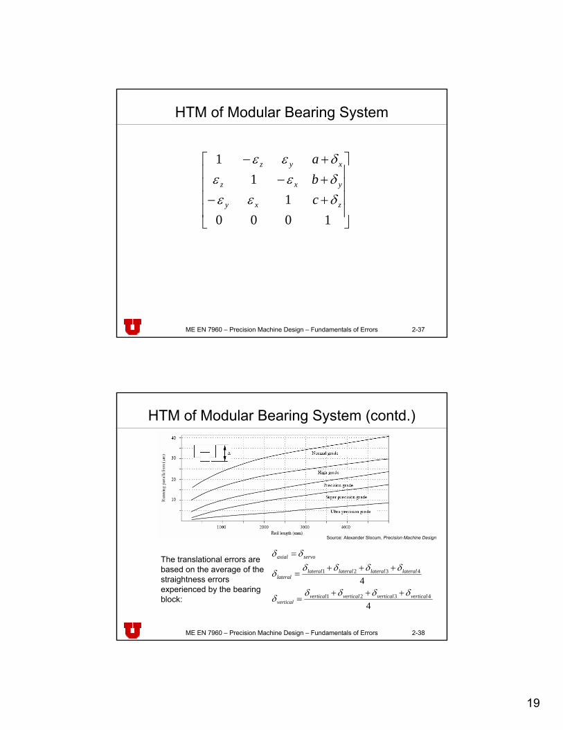
HTM of Modular Bearing System (contd.)
4
44321
4321
verticalverticalverticalverticalvertical
laterallaterallaterallaterallateral
servoaxial
δδδδδ
δδδδδ
δδ
+++=
+++=
=The translational errors are based on the average of the straightness errors experienced by the bearing block:
Source: Alexander Slocum, Precision Machine Design

20
ME EN 7960 – Precision Machine Design – Fundamentals of Errors 2-39
HTM of Modular Bearing System (contd.)
• The angular errors are based on the differences in the average straightness errors experienced by pairs of bearing blocks acting across the carriage:
L
L
W
laterallaterallaterallateral
vertical
verticalverticalverticalvertical
lateral
verticalverticalverticalvertical
axial
22
22
22
2143
4321
4132
δδδδ
ε
δδδδ
ε
δδδδ
ε
+−
+
=
+−
+
=
+−
+
=
ME EN 7960 – Precision Machine Design – Fundamentals of Errors 2-40
HTM of Modular Bearing System (contd.)
• Note we assumed for the straightness we assumed all the errors are acting in the same direction
• Here we assume one set of errors acts up, and the other acts down
• This is very conservative (makes up for other effects we might miss)

21
ME EN 7960 – Precision Machine Design – Fundamentals of Errors 2-41
Linear Error Plot
Straightness error of a kinematically (statically determined) supported linear axis (5 rolling element bearings on a vee and flat)
Source: Alexander Slocum, Precision Machine Design
ME EN 7960 – Precision Machine Design – Fundamentals of Errors 2-42
Fourier Transformation of Linear Error Plot
• The Fourier Transformations when plotted as the error amplitude as a function of wavelength is an invaluable diagnostic tool
• The wavelength of rolling elements is 2πDSource: Alexander Slocum, Precision Machine Design

22
ME EN 7960 – Precision Machine Design – Fundamentals of Errors 2-43
HTM of Rotary Axis
⎥⎥⎥⎥
⎦
⎤
⎢⎢⎢⎢
⎣
⎡
++−−−+
−
=
1000coscossinsincoscossinsinsincossincoscossinsinsinsincoscossincoscossinsin
sinsincoscoscos
zyxzyxzxzxzyx
yyxzyxzxzxzyx
xyzyzy
TnerrR
δεεθεεθεθεθεεδεεθεεθεθεθεεδεθεθε
Source: Alexander Slocum, Precision Machine Design
ME EN 7960 – Precision Machine Design – Fundamentals of Errors 2-44
Rotary Errors
• This general result may also be used for the case of a linear motion carriage if εz is substituted for θz
• Radial error motion is conservatively estimated to be the ABEC bore tolerance
• Tilt error motion is conservatively estimated to be the ABEC axial tolerance divided by the bearing OD

23
ME EN 7960 – Precision Machine Design – Fundamentals of Errors 2-45
Rotary Error Plot
• The average error motion is indicative of the form error that will be imparted to the part when held in a lathe spindle
• The asynchronous error motion is indicative of the surface finish that will be obtained
Source: Alexander Slocum, Precision Machine Design
ME EN 7960 – Precision Machine Design – Fundamentals of Errors 2-46
Fourier Transformation of Radial Error
• Spindle speed: 1680 rpm (28 Hz)• Bearing ID: 75 mm• Bearing OD: 105 mm
• Number of balls: 20• Ball diameter: 10 mm• Contact angle: 15
Source: Alexander Slocum, Precision Machine Design
24
ME EN 7960 – Precision Machine Design – Fundamentals of Errors 2-47
Combinational Ruler for 3 Common Types• Random - under apparently equal conditions at a given
position, errors that do not always have the same value, and can only be expressed statistically
• Systematic - which always have the same value and sign at a given position and under given circumstances– Generally can be correlated with position along an axis and can
be corrected• If the relative accompanying random error is small enough
• Hysteresis - a systematic error which in this instance is separated out for convenience– Usually repeatable, sign depends on the direction of approach,
and magnitude partly dependent on the travel– May be compensated for if the direction of approach is known
and an adequate pre-travel is made