Embed Size (px)
Citation preview

ME 450
Winter 2009
Project 4: Fine Needle Aspiration
Final Report
April 21, 2009
Team 4: Nathan Brown
Mary Kay DuBay
Jeffrey M. Otto
Joel Van Sloten
Sponsor: Professor Robertson Davenport, M.D.
Instructor: Professor Hong G. Im

2
EXECUTIVE SUMMARY
Design Problem
Current fine needle aspiration (FNA) devices have a “pistol grip” style interface, with a trigger to apply
suction to the needle tip. In this configuration, the user‟s entire arm is moved to position the needle.
There is a need for a device that can be operated using the fingertips, where fine motor control can sense
differences in tissue consistencies and control suction levels.
Customer Requirements and Engineering Specifications
The device must perform all the same functions as the existing devices, while allowing for greater fine
motor control and sensitivity during the aspiration process. Fine motor control can be accomplished by
using a smaller device, operable with the fingertips on one hand (either hand), that allows the user to
adjust the amount of suction applied to the needle during aspiration. The device must collect a sufficient
amount of tissue for testing (at least the volume of a needle), and must be able to express the sample with
the same ease as current devices. A disposable device should cost less than $3 per unit, and a reusable
device should cost no more than $100. Lastly, the device must be safe.
From these customer requirements, we defined our engineering specifications. The most important
specification for the new design is a pen-like cylindrical shape that can be manipulated with the fine
motor control of the fingers on one hand. The table below shows the measured engineering specifications
for our design. Additional specifications are incorporating the standard Luer-Lok™ feature that enables
the attachment of various sized needles, and that the pressure vacuum is controlled by a single action.
Specification Diameter Length
Suction
Pressure
Collection
Volume Activation Force Weight
Target ≤ 2.5 cm 11.25-15 cm < 5 kPa ≥ 0.04 cc < 20N < 250 g
Concepts Considered
After generating and evaluating several concepts in the mechanical (valve design, push slider, direct
slider, spring and locking slider, spring loaded, lever arm, live hinge, and rack and pinion), electrical
(linear actuator), and pressure (shoe pump and diaphragm valve) categories, we decided to pursue the
valve design, specifically considering a pinch, gate, and ball valve.
Concept Selection Methodology
Our concept selection methodology involved using Quality of Functional Deployment charts to rank
which concepts met customer requirements most effectively. We also used scoring matrices, evaluated
with the requirements of team members and Professor Davenport.
Engineering Challenges
In developing mock-ups, our main challenge was to create effective seals in our pinch, gate, and ball
valve design concepts. Appropriate materials selection was an important consideration, so that adhesives
would bond and proper shapes could be manufactured.
Rationale for the Final Concepts
Mock-ups and trial and error testing were used to create the final pinch and gate valve design concepts.
Deliverables for Design Expo
For the Design Expo, we re-built our pinch and gate valves into more polished final prototypes by making
slight modifications to the preexisting mockups. We also prepared verbal presentation material, in
addition to a poster and demonstration for Expo attendees.

3
TABLE OF CONTENTS
INTRODUCTION AND INFORMATION SOURCES ....................................................................................... 4
ENGINEERING SPECIFICATIONS .................................................................................................................. 5
CONCEPT GENERATION ................................................................................................................................. 7
CONCEPT SELECTION ..................................................................................................................................... 9
CHOSEN DESIGN DESCRIPTION.................................................................................................................. 11
MOCK-UP DESCRIPTIONS ............................................................................................................................ 13
ENGINEERING DESIGN PARAMETER ANALYSIS .................................................................................... 16
FINAL DESIGN DESCRIPTION ...................................................................................................................... 18
PROTOTYPE FABRICATION ......................................................................................................................... 20
PROTOTYPE DESCRIPTION ......................................................................................................................... 23
VALIDATION .................................................................................................................................................... 25
MASS PRODUCTION MANUFACTURING ................................................................................................... 27
PROJECT TIMELINE ...................................................................................................................................... 28
RECOMMENDATIONS .................................................................................................................................... 29
CONCLUSIONS ................................................................................................................................................ 30
ACKNOWLEDGEMENTS ................................................................................................................................ 31
REFERENCES AND INFORMATION SOURCES .......................................................................................... 32
APPENDIX A: TECHNICAL BENCHMARKS ............................................................................................... 33
APPENDIX B: HAND STRENGTH CHART ................................................................................................... 34
APPENDIX C: CONCEPT SKETCHES ........................................................................................................... 35
APPENDIX D: CONCEPT SELECTION AIDS ............................................................................................... 42
APPENDIX E: GANTT CHART ....................................................................................................................... 44
APPENDIX F: BILL OF MATERIALS ............................................................................................................ 45
APPENDIX G: FINAL PROTOTYPE DRAFTING ........................................................................................ 46
APPENDIX H: PINCH VALVE OPERATION AND PROCEDURAL INSTRUCTIONS .............................. 49
APPENDIX I: GATE VALVE OPERATION AND PROCEDURAL INSTRUCTIONS ................................. 53
APPENDIX J: DESIGN EXPO POSTER.......................................................................................................... 57
APPENDIX K: MATERIALS FUNCTIONAL PERFORMANCE .................................................................. 58
APPENDIX L: ENVIRONMENTAL IMPACT ................................................................................................ 61
APPENDIX M: PROCESS SELECTION ASSIGNMENT ............................................................................... 69
APPENDIX N: SAFETY REPORT ................................................................................................................... 76

4
INTRODUCTION
Our sponsor, Professor Robertson Davenport, performs fine needle aspiration (FNA) biopsies in the
Department of Pathology at the UM Hospital. He has experimented with various devices and methods,
but has yet to find a fine needle aspiration device that meets all of his needs as a cytopathologist.
Professor Davenport currently uses a Cameco® Syringe Pistol to perform his biopsies, although this
device is less than ideal for several reasons (Figure 1). The most frustrating aspect of this design is that
its use of a hand grip to apply suction ultimately requires whole arm movement for needle placement.
When using the whole arm, even slight movements in the arm have significant effects on the sensitive
needle/tissue interface and make needle placement more difficult. The absence of fine motor control also
prevents the user from distinguishing between varying tissue consistencies, which is a crucial step in FNA
procedures. Another shortcoming of this design is that the size of the device can make it very challenging
to maneuver around certain areas of the body without rotating the hand into awkward positions while
performing the procedure. Professor Davenport believes the procedure could be greatly improved by
developing a device that possesses a more pen-like shape that can be manipulated with the fine motor
control of the fingers on either hand. Given the compact nature of this idea, the device would have to
incorporate a convenient method for applying suction to extract the tissue, maintaining a vacuum, and
then emitting the tissue sample.
Figure 1: Cameco Syringe Pistol® [1]
Considering all parts of this design problem, a specific set of customer requirements was defined. The
new fine needle aspiration device must: be operated with fine motor control, be operated with the
fingertips of one (and either) hand, have user-controlled suction, be simple to operate, be sterile, be safe
for the operator, have the ability to break up tissue, be affordable, be able to collect a large sample size in
the needle, have user-controlled suction release, and be able to express the sample easily. Our ultimate
goal is to produce a completed device that could be immediately implemented into use in the medical
community and would outperform existing devices with its ease of use.
INFORMATION SOURCES
Our main source of information regarding FNA procedures and current FNA devices is our sponsor,
Professor Davenport. Also, as mentioned in design review #1, Dr. Stewart Knoepp has assisted our team
by helping us better understand the procedure, describing to us his own experiences with the current
device and explaining his own ideas about changes that could be made to improve the current procedure
[2].
Additionally, since design review #1, our team gained access to the ME 395 Laboratory at the University
of Michigan. In the lab, we used testing equipment to finalize the engineering specifications for our
design problem. Specifically, we used an Instron 4466 force transducer with a testing rate of 1 in/min to
determine the forces required to extract the plunger in a 1cc, 3cc, and 10cc syringe to 2cc (1cc for the 1cc

5
syringe) of displacement. We also used a standard mass scale in the laboratory to take mass
measurements of the syringes.
Technical Benchmarks We would like to recap the three selected FNA devices that are already in existence as a basis for
comparison. The Cameco Syringe Pistol® is known as the industry standard for FNA devices. The
syringe pistol, shown in Figure 1 on page 4, is a reusable device that incorporates a standard disposable
syringe and needle. The syringe pistol is operated by manually squeezing the “trigger,” which pulls the
plunger back, creating the vacuum necessary to capture the tissue samples. The Tao Aspirator®, shown
in Appendix A.1 on page 33 is a commercially available design that is designed to be held like a pencil.
It is another example of a reusable design that uses the standard disposable needle and syringe. It is a
finger-gripped style, which should allow for greater fine motor control. The plunger in this design is
pulled back by a pre-loaded spring that is released by pushing a button on the device. The Cytec®
device, shown in Appendix A.2 on page 33 is similar to our target design, but is not available in the US.
This non-disposable design incorporates the use of a unique disposable vacuum chamber and standard
disposable needle. The basic design has a pen-like shape that is easily manipulated by the fine motor
control of the fingers. The device is “cocked” to a certain suction level before the aspiration takes place.
Once the needle is inserted, a button turns on the suction, while a second button relieves the pressure
when the procedure is complete.
Colleague Information We were also fortunate enough to receive a reference table of maximum hand strengths of the human
hand from our classmate and colleague, Max Bajcz. We used the information in this table as a guideline
for the maximum activation force for our device. In particular, we used the maximum finger gripping
strength, or strength of pinching your thumb and index finger together, for a “weak woman” as a starting
point for a maximum activation force.
ENGINEERING SPECIFICATIONS
Engineering specifications, the major theme of our first design review, are the critical foundation upon
which all of our concept designs are centered. The success of our final product will not be judged on how
cool it looks, but rather on how well it satisfies the desired design specifications. It is important that we
remain continuously aware of the specifications requested by our sponsor and those we have instituted
ourselves. Many of our design specifications were discussed at length in design review #1, but a number
of specifications have undergone further analysis since that time so it seems wise to review all of the
specifications pertaining to our project.
User Requirements
Through meetings and ongoing correspondence with our sponsor, Professor Davenport, we have
determined several of his key specifications. The device must perform all the same functions as the
existing devices, while allowing for greater fine motor control and sensitivity during the aspiration
process. Fine motor control can be accomplished by a device operable with the fingertips on one hand
(and either hand) that allows the user to adjust the amount of suction applied to the needle during
aspiration. In the current devices, the needle tip breaks up tissue in the mass so it can be collected for
testing. The user must be able to release the suction while the needle is still in the patient, preventing the
suction from taking in blood or fat from areas surrounding the mass while the needle is being pulled out
of the skin. The device must collect a sufficient amount of tissue for testing (at least the volume of a
needle), and must be able to express the sample with the same ease as current devices. A disposable
device should cost less than $3 per unit, and a reusable device should cost no more than $100. Lastly, the
device must be safe. For the patient, this means that it must be sterile, and therefore, a reusable device

6
should be autoclave-able (for sterilization). For the doctor, the device must present no more opportunity
for an accidental needle prick than the risk already present with syringes and needles.
Relative Importance of User Requirements
Professor Davenport has led us to understand that fine motor control is his primary requirement for this
device. He has described the aspiration process to us and shared some of his experiences performing the
procedure. His descriptions have indicated that lack of fine motor control is the greatest disappointment
in all of the current devices. As such, creating a device that can be operated by fine motor control is of
utmost importance, and all other potential design features unrelated to this outcome are secondary
concerns. Naturally, it is important that any device we design is capable of performing all the same tasks
as or more effectively than performed by current devices. Designing a disposable device is certainly a
point of interest for Professor Davenport, though he has assured us that this is not a crucial feature for our
design.
Previously, we compared the customer requirements and technical specifications to define a set of
engineering requirements in a Quality of Function Deployment chart (shown in Appendix D.1 on page
42). The results of that chart agreed with Professor Davenport‟s requirements, ranking fine motor control
(including user stability and device weight) as the top priority.
Determining Specifications
Various levels of testing were performed to determine numerical specifications for the final device shown
in Table 1 below. An obvious specification is the size of the design. We assumed a cylindrical shape for
the device and practiced holding and manipulating cylinders of different sizes to determine an acceptable
size for a finger-operated device. Next, we specified the weight of the device by holding objects of
different weights and determining qualitatively the maximum weight that still allows for fine motor
control. The force required to activate the suction in the needle is a driving specification for this design.
We tested how much force is required to retract syringe plungers to displacements of 2cc in the ME 395
lab with the assistance of Tom Bress. The results of our tests, shown in Table 2 on page 7, indicated that
the force required to retract a 10cc syringe is nearly ten times the force required for a 3cc syringe. We
also must insure that the required user input force is within the capability of a human hand. We were
especially interested by the amount of force that can be exerted by a pinching motion between two
fingers. Thanks to some data provided by classmate Max Bajcz, we determined a maximum activation
force of 20N (See Appendix B on page 34). This includes a safety factor of 2 to insure we remain well
below the limit of human capability. Since the existing devices can collect up to several cubic
centimeters of tissue and blood, we decided to specify a minimum volume of tissue the device must be
able to collect. Analysis of the sample requires no more tissue than what can be collected in the needle of
a syringe, so we determined the volume of a standard gauge needle and made it a minimum requirement.
Table 1: Engineering Specifications
Specification Diameter Length
Suction
Pressure
Collection
Volume Activation Force Weight
Target ≤ 2.5 cm 11.25-15 cm < 5 kPa ≥ 0.04 mL < 20N < 250 g

7
Table 2: Force to pull back plungers
Syringe Capacity (cc) 1 3 10
Force to pull plugged plunger to 2cc
displacement (N)
1.74* 5.2 45.95
Force to pull plunger to 2cc
displacement in an apple (N)
2.25* 5.4 ----
Syringe Weight (g) 5.44* 9.98 12.47
* 1cc syringe plunger pulled back all the way to 1cc displacement
Benchmarks
We compared our design to the technical benchmarks (Cameco Syringe Pistol®, Tao Aspirator®, and
Cytec device®), described in detail on page 5. The size and shape of all our concepts were specifically
selected in order to allow for maximum control with the hand and fingers, rather than the arm. Because
many of our concepts are relatively small compared to the benchmarks, they are likely to weigh less. The
suction pressure and collection volume are more dependent on the user than they are on the design of the
device. In our concepts, the user can apply the same amounts of pressure and collect the same volume of
tissue as with the benchmarked devices. The method of creating suction does vary between concepts, and
because some concepts may be operated by finger forces rather than hand forces, it may be more difficult
to apply suction in some. All of the benchmarked designs are reusable devices, but a number of our
concepts are disposable, which is desirable, according to Professor Davenport.
Tradeoffs
The specifications had not undergone much evolution in the project. From the beginning, the importance
of a small device was greatly emphasized and many of our specifications were determined accordingly.
Ultimately we were seeking to design a compact device and often designing small devices can become
rather challenging, particularly when they are technologically complex. Our ideas to create a simply-
operated device allowed us more breathing room where size was concerned. The activation force, or
force required to retract the plunger of the syringe back to 2cc, had been a strong point of interest during
early stages of concept generation. If the user is required to apply this force during the procedure we
want it to require the least amount of effort possible, but until originally we didn‟t know how much force
would actually be necessary. Having gathered this data, we were more aware of our limitations and took
them into consideration as we moved forward in the design process. For example, the possibility of a
design that incorporated a linear actuator had brought to light a number of obvious tradeoffs. While the
linear actuator would allow the device to operate by the simple push of a button, it is somewhat large and
heavy compared to other designs and would also require an external power source. Because “large” and
“heavy” are very much in disagreement with our number one priority to design a small device that is
operable by fine more control, such trade off‟s would not be considered worthwhile at this stage.
CONCEPT GENERATION
Whether we follow standard engineering design methods shown in an IDEO video in our ME 450 design
class, or read over our lecturer Professor Skerlos‟ posted presentation, the first two steps necessary to
generate design concepts are functional decomposition and brainstorming.
Functional Decomposition
In the functional decomposition step of the concept generation process, the desired outcome is broken
down into the operations required to get to the outcome. In the case of designing a fine needle aspiration
device, the device must 1) pierce the skin, 2) break up the tissue, 3) retrieve a tissue sample, and 4)
discharge the tissue sample.

8
Brainstorming
In the brainstorming step of the concept generation process, we compiled a list of various ways to
accomplish each of the functional decomposition steps. We generated several ideas that would work well
for one functional decomposition step, but did not seem to directly fulfill the needs of all the other
functional decomposition steps. Nevertheless, we still listed all of our ideas, some reasonable, and some
outrageous, in hopes that a few unlikely ideas could spur on our creativity into one state-of-the-art idea.
Some of the ways we brainstormed to pierce the skin include using a guitar string, bullet, porcupine
needle, screw, nail, laser, thin straw, needle, pin, tack, briar, nettle, bee stringer, plastic needle, and
capillary tube. Then, to break up the tissue, a screw, reverse auger, ultrasound, chemical reaction,
tweezers, scissors, jackhammer, sandblaster, squiggle pen, sharp needle, sharp plastic needle, or fishook
could be used. The third functional decomposition step, retrieving a tissue sample, could be
accomplished using a straw with suction, conveyor belt, screw, gravity, pressure increase in the tissue,
siphon, pulsed low pressure, or esophogus contraction. Various ways of accomplishing the final function,
discharging the tissue sample, include using reverse pressure, a mechanical push, a siphon, chemical
precipitation, or gravity.
In addition the the exact functional decomposition steps, we also brainstormed different types of energy
sources that could be harnessed to remove the tissue. A mechanical energy source could be the force of a
finger, electrical energy sources could include AC power and a battery, and a chemical energy source
could involve a gas producing or gas consuming reaction. Looking into more abstract energy sources, we
hypothesized that a thermal energy source could include freezing or „melting‟ the tissue, an ultrasonic or
microwave energy source could use sound waves to vibrate tissue cells loose, and a solar energy source
could involve focusing light to potentially burn through the tissue. A magnetic energy source was
considered, but could only work if tissue was polarized.
Concept Generation Results
From the functional decomposition and brainstorming steps, we drew conclusions and created concepts
for our design. Looking at the list of ways to pierce the skin, we concluded that using a needle will be the
best option. Because a needle is currently the standard device used to pierce the skin, we know that it
meets the strength requirements necessary for the fine needle aspiration process. A needle is sterile and
biocompatible. Also, a needle is minimally invasive, creating a minimal amount of pain and scarring for
the patient.
Similarly, looking at the list of ways to break up the tissue, a sharpened needle was concluded to be the
best option. Again, the needle‟s strength, biocompatability, and minimal invasion set it apart from some
of the other ideas for breaking up tissue. Additionally, we concluded that it would be better to use one
device (a needle) to complete two steps in the functional decomposition (pierce the skin and break up the
tissue) than it would be to attach an additional device for breaking up the tissue. We plan to use the Luer-
Lok™ design for our needle attachment because it is a readily-accessible, existing standard (Luer-Lok™
is a trademark of Beckton-Dickson Co).
Although we concluded that a Luer-Lok™ needle will be the best idea for piercing the skin and breaking
up the tissue, we still created many concepts using our various ideas for retrieving and discharging the
tissue sample. All of our concepts, including the obviously infeasible ones, are documented in Appendix
C on pages 35-41. We classified the concepts into three main categories: mechanically actuated,
electrically powered, and pressure driven. Some of the main concepts included in the appendix are the
mechanical valve design and push slider design, the electrical linear actuator design, and the pressure-
driven shoe pump design.

9
Mechanical
The valve design (Appendix C.1 on page 35) is a mechanical design, and also is the only potentially
disposable design. It would be placed between the standard needle attachment and the Luer-Lok™ of the
syringe. The valve could be opened and closed throughout the fine needle aspiration procedure to control
the suction level. The push slider design (Appendix C.3 on pages 35-36) converts a vertical finger force
on the syringe pen to a horizontal force on the syringe plunger, to control suction. Several variations of
this direct finger force, mechanically translated into syringe slider action, were created. Some other
concepts in this category included the direct slider, spring and locking slider, spring loaded, lever arm,
live hinge, and rack and pinion, and are shown in Appendix C.
Electrical
The electrical linear actuator design (Appendix C.2 on page 35) is our only design to involve an electrical
energy source. It would use an electrical power source and linear actuator to move a syringe plunger up
and down, controlling the pressure/suction level.
Pressure
The shoe pump design (Appendix C.10 on page 38) is similar to the push slider design because it converts
a finger force perpendular to the syringe pen axis to a pressure differential to control suction. However,
the force translated in this concept involved pressure rather than a mechanical set-up. Another pressure-
related concept included the diaphragm valve, which is shown in Appendix C.
CONCEPT SELECTION
Following the functional decomposition, brainstorming, and concept generation activities, our team was
faced with choosing between eleven potential designs. In order to evaluate each of the designs in a
qualitative manner, we made use of a scoring matrix, similar to a Quality of Function Deployment
diagram. However, in this case, each of the designs was weighed against the technical requirements of
the design.
Technical Requirement Weights
The first step in setting up a design scoring matrix is to clearly define the technical requirements used in
the scoring matrix. First, the device should be lightweight in order for the user to maintain fine motor
control during the procedure. Secondly, the diameter of the device is a crucial requirement and a big part
of our design problem. A device that can be grasped like a pencil rather than held like a pistol would
greatly benefit the user. We also defined a requirement to help distinguish the user stability, as well as
one that defined the amount of motion required to use the device, user range of motion. Device flexibility
reflects the way the device can conform to the user‟s fingers. Another important requirement to maintain
fine motor control was the characteristic length. The characteristic length is defined by the distance from
the user‟s fingertips during the procedure to the needle tip. We felt that a device that would minimize this
length would give the user better control and a sense of feel during the procedure. The device should also
have a relatively low market price, especially if it would be a feasible solution to our design problem.
Related to this requirement was the manufacturability of the device. If the design were to be mass
produced, a disposable device should cost less than $3 per unit, and a reusable device should cost no more
than $100. Next we considered the pressure activation force which is the force required by the user to
activate the suction pressure during the procedure in order to collect the tissue cells that are removed.
Finally, the aesthetics of the device should always be considered so the device‟s appearance is not
intimidating for a patient.
10
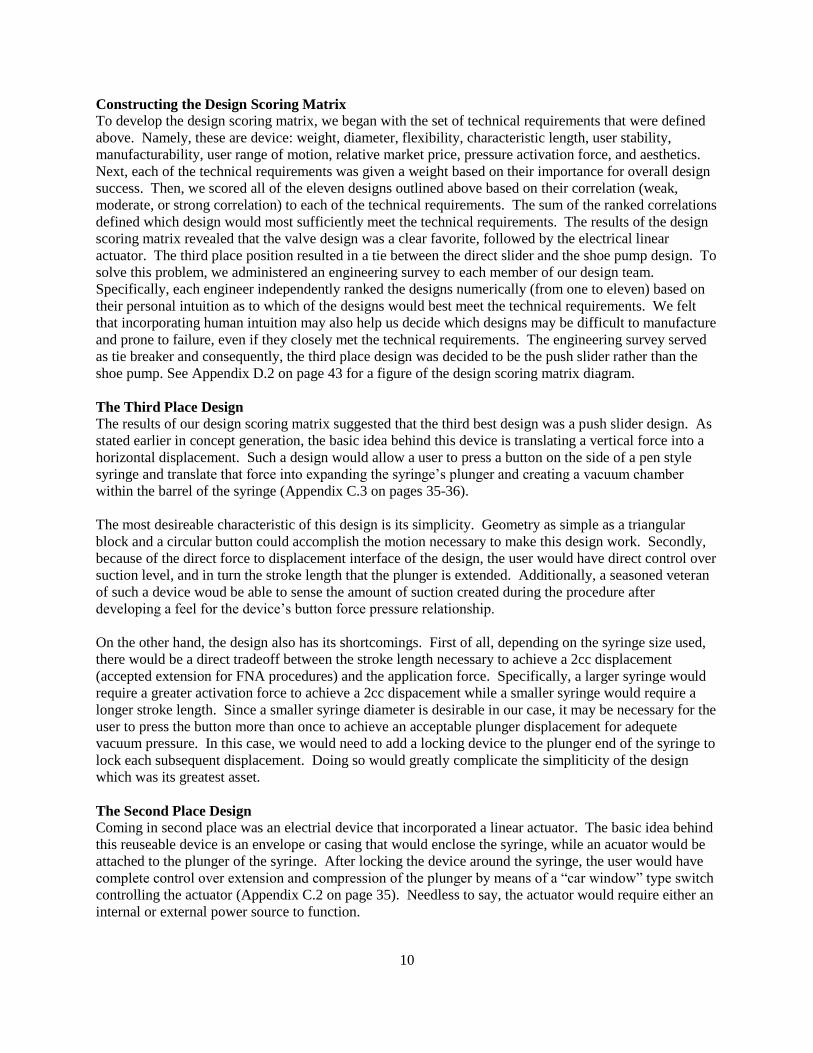
Constructing the Design Scoring Matrix To develop the design scoring matrix, we began with the set of technical requirements that were defined
above. Namely, these are device: weight, diameter, flexibility, characteristic length, user stability,
manufacturability, user range of motion, relative market price, pressure activation force, and aesthetics.
Next, each of the technical requirements was given a weight based on their importance for overall design
success. Then, we scored all of the eleven designs outlined above based on their correlation (weak,
moderate, or strong correlation) to each of the technical requirements. The sum of the ranked correlations
defined which design would most sufficiently meet the technical requirements. The results of the design
scoring matrix revealed that the valve design was a clear favorite, followed by the electrical linear
actuator. The third place position resulted in a tie between the direct slider and the shoe pump design. To
solve this problem, we administered an engineering survey to each member of our design team.
Specifically, each engineer independently ranked the designs numerically (from one to eleven) based on
their personal intuition as to which of the designs would best meet the technical requirements. We felt
that incorporating human intuition may also help us decide which designs may be difficult to manufacture
and prone to failure, even if they closely met the technical requirements. The engineering survey served
as tie breaker and consequently, the third place design was decided to be the push slider rather than the
shoe pump. See Appendix D.2 on page 43 for a figure of the design scoring matrix diagram.
The Third Place Design The results of our design scoring matrix suggested that the third best design was a push slider design. As
stated earlier in concept generation, the basic idea behind this device is translating a vertical force into a
horizontal displacement. Such a design would allow a user to press a button on the side of a pen style
syringe and translate that force into expanding the syringe‟s plunger and creating a vacuum chamber
within the barrel of the syringe (Appendix C.3 on pages 35-36).
The most desireable characteristic of this design is its simplicity. Geometry as simple as a triangular
block and a circular button could accomplish the motion necessary to make this design work. Secondly,
because of the direct force to displacement interface of the design, the user would have direct control over
suction level, and in turn the stroke length that the plunger is extended. Additionally, a seasoned veteran
of such a device woud be able to sense the amount of suction created during the procedure after
developing a feel for the device‟s button force pressure relationship.
On the other hand, the design also has its shortcomings. First of all, depending on the syringe size used,
there would be a direct tradeoff between the stroke length necessary to achieve a 2cc displacement
(accepted extension for FNA procedures) and the application force. Specifically, a larger syringe would
require a greater activation force to achieve a 2cc dispacement while a smaller syringe would require a
longer stroke length. Since a smaller syringe diameter is desirable in our case, it may be necessary for the
user to press the button more than once to achieve an acceptable plunger displacement for adequete
vacuum pressure. In this case, we would need to add a locking device to the plunger end of the syringe to
lock each subsequent displacement. Doing so would greatly complicate the simpliticity of the design
which was its greatest asset.
The Second Place Design Coming in second place was an electrial device that incorporated a linear actuator. The basic idea behind
this reuseable device is an envelope or casing that would enclose the syringe, while an acuator would be
attached to the plunger of the syringe. After locking the device around the syringe, the user would have
complete control over extension and compression of the plunger by means of a “car window” type switch
controlling the actuator (Appendix C.2 on page 35). Needless to say, the actuator would require either an
internal or external power source to function.

11
At first glance, the electrical linear actuator design seems like it may be an unrealistic and infeasable
option for our design challenge. However, it has a few notable characteristics that allowed it to score
exceptionally well in our design scoring matrix. First of all, incorporating a machine (actuator) into the
design would allow for the user of the device to concentrate solely on performing the FNA procedure
rather than worrying about having to squeeze or apply a force to achieve suction. Along the same lines,
since the actuator can be controlled by a switch, the characteristic length (distance from finger tip to
needle tip) could be minimized. Such a feature could increase the sense of feel during the procedure.
Lastly, in this design the user has direct control over the amount of suction used during the procedure and
could modify this as they saw fit.
The downsides of the electrical linear actuator design are quite obvious. First of all, our specification for
a weight limit places major constraints on the size of our actutor, button, and power source. Second,
heavier objects have a tendency to be bulky and uncontrollable, especially when the center of gravity is
not positioned carefully. This could drastically compromise the fine motor control of the device.
Additionally, the need for incorporating a power source, either internal or external, adds extra cost,
maintainance, and replacement issues that the other designs escaped. Furthermore, the speed of the
actuator could compromise the time it takes to apply suction during in the procedure which would be
undesirable.
CHOSEN DESIGN DESCRIPTION
Based on our specifications and the customer requirements, we have decided that the valve design, shown
in Figure 2, is the best design to achieve the desired results. This section will describe the device, its
operation, and how it was selected as the best design.
Figure 2: Valve Design
Device Description
The valve design device will make use of the standard equipment already used in fine needle aspiration
procedures. The needle and 10cc syringe are considered to be the standard for this procedure, and we do
not want to change that.
The device will consist of two main parts. The first part is a valve with Luer-Lok™ connectors on either
side. The valve will be cylindrical, with a diameter roughly equivalent to the diameter of the syringe. On
the exterior of the cylinder, there will be a control to open and close the valve. The second part of the
device is a chock designed to fit between the syringe plunger pull tab and the syringe body tabs, or some
other type of syringe plunger locking mechanism.
Device Operation
To operate the device, the cylindrical valve will first be threaded onto the syringe tip, and the aspiration
needle will be threaded onto the opposite end of the valve. The cylinder will function as an on/off valve
for the syringe, allowing syringe pressure to reach the needle tip when the valve is open.
Once the valve, needle, and syringe are assembled, the syringe plunger will be pulled back to about 0.5cc
displacement, and the valve placed in the closed position. Then, the plunger will be pulled back to the
12
full 10cc displacement. This is where the second part of the device comes into play. While holding the
plunger out at the 10cc position, the chock will be inserted between the syringe body and the plunger tab,
holding/locking the plunger at the 10cc position. The syringe barrel now contains a vacuum, which can
be released with the valve.
The user will then hold the device like a pen or marker, and proceed to insert the needle into the lumped
tissue. Once the needle has been inserted, the user will press the valve button to open the vacuum present
in the syringe barrel to the needle tip. The user will be free to move the needle around in the lump with
the vacuum applied. Once the user has collected enough sample tissue, the button will close the valve,
shutting off the vacuum to the needle tip. The user will remove the needle from the lump without danger
of sucking up blood in the needle tip.
Once the needle has been removed from the lump, the chock/lock will be removed, allowing the plunger
to return to its position of 0.5cc displacement. The valve will then be opened, and the plunger depressed
to express the desired amount of sample onto a slide for testing.
Valve Type
By Design Review #2, a final valve design had not yet been determined; however, we had generated three
valve concepts that we believed could easily be activated and maintain a pressure differential of nearly
100 kPa for several minutes. The three designs are the gate valve, ball valve, and pinch valve. After
completing a valve scoring matrix (Appendix D.3 on page 43), we decided to use the pinch valve as our
target design.
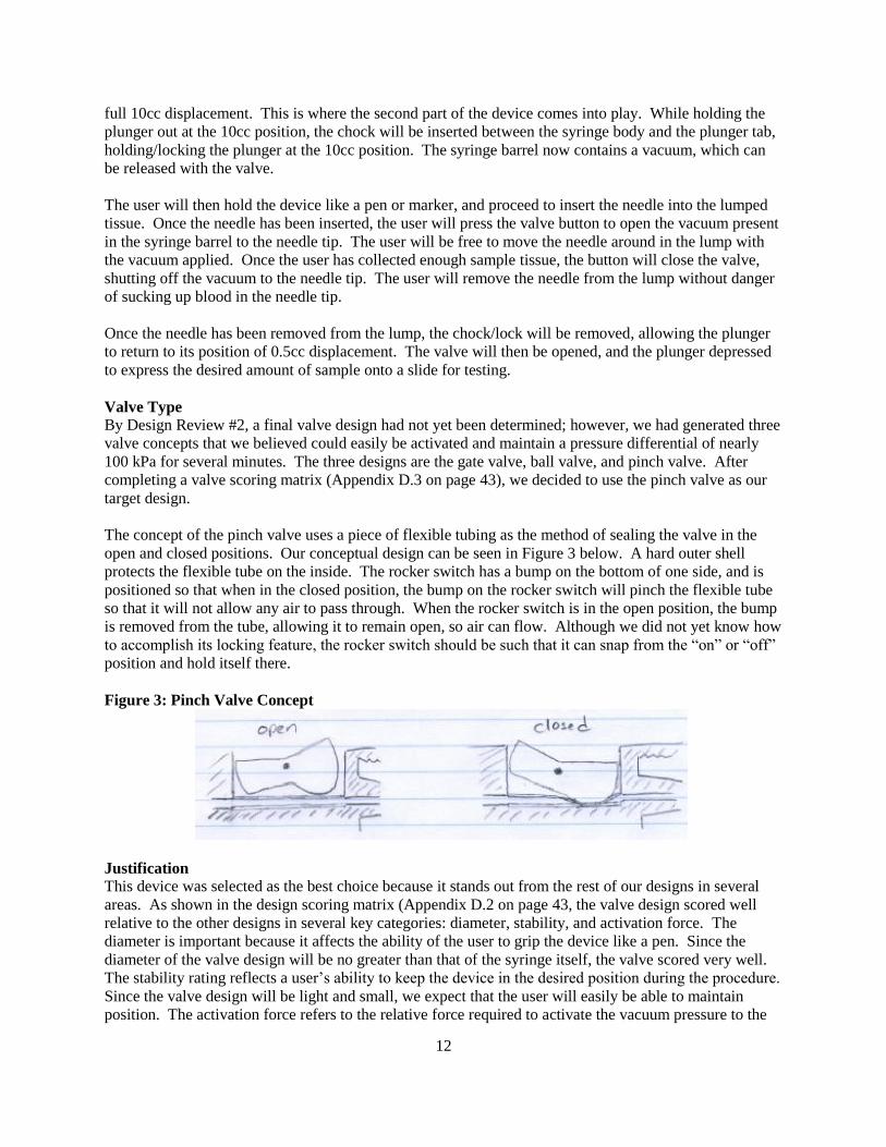
The concept of the pinch valve uses a piece of flexible tubing as the method of sealing the valve in the
open and closed positions. Our conceptual design can be seen in Figure 3 below. A hard outer shell
protects the flexible tube on the inside. The rocker switch has a bump on the bottom of one side, and is
positioned so that when in the closed position, the bump on the rocker switch will pinch the flexible tube
so that it will not allow any air to pass through. When the rocker switch is in the open position, the bump
is removed from the tube, allowing it to remain open, so air can flow. Although we did not yet know how
to accomplish its locking feature, the rocker switch should be such that it can snap from the “on” or “off”
position and hold itself there.
Figure 3: Pinch Valve Concept
Justification
This device was selected as the best choice because it stands out from the rest of our designs in several
areas. As shown in the design scoring matrix (Appendix D.2 on page 43, the valve design scored well
relative to the other designs in several key categories: diameter, stability, and activation force. The
diameter is important because it affects the ability of the user to grip the device like a pen. Since the
diameter of the valve design will be no greater than that of the syringe itself, the valve scored very well.
The stability rating reflects a user‟s ability to keep the device in the desired position during the procedure.
Since the valve design will be light and small, we expect that the user will easily be able to maintain
position. The activation force refers to the relative force required to activate the vacuum pressure to the

13
needle tip during the procedure. Since the valve requires only a minimal force to press the button, the
design scored well in the activation force. The complete scoring can be seen in Appendix D.2 on page 43.
Note that, although the pinch valve was selected as the best choice through the use of a scoring matrix,
the gate valve and pinch valve are still potentially feasible designs. We decided to pursue the
development of all three of these designs unless they proved to be infeasible at some point.
MOCK-UP DESCRIPTIONS
Our mock-ups are full scale, fully developed models of our final design. Each mock-up exhibits the same
functionality as is expected of the final design, so we will not repeat the details of what the mock-up
design is, how it works, and why it works in this section. We will simply discuss the relationship
between our current mock-up and our final design in detail, explaining the larger points of similarity and
difference. We will also state how each mock-up proves the most important elements of our final design.
Pinch Valve
The pinch valve mock-up, shown in Figure 4, proves that we derived a good solution to the fine needle
aspiration device problem presented by Professor Davenport. The pinch valve mock-up proves the most
important elements of the final design. The fine motor control force of a fingertip can control the valve‟s
push button dowel. The push button is able to pinch a pressurized tube, allowing suction to be held and
released throughout the fine needle aspiration procedure. Also, the mock-up has a saw-tooth, locking
syringe plunger, as will be used to hold and release suction in the final design.
Figure 4: Pinch Valve
The pinch valve mock-up validates our final design. It is not a scale up or a scale down of our actual
design, but is scaled appropriately to resemble our final design within engineering specifications. The
mock-up uses the standard Luer-Lok™ fittings, syringe barrels, and needle sizes as will be used in the
actual, final design.
Although the mock-up proves the validity of the most important elements of our design, it was anticipated
that there would be significant differences between the final design and the mock-up. For example, in our
mock-up, we added circular end caps to the valve casing ends to provide more area to attach the Luer-
Lok™ fittings. Next, we attached the latex tubing to the Luer-Lok™ barbs and glued the Luer-Lok™
ends to the end caps, and the end caps to the valve casing. In the final design, it was likely the Luer-
Lok™ fittings would be glued directly to the valve casing, which would be made from solid
polypropylene stock. This would eliminate the need for an end cap. Another area of improvement in the
pinch valve design would be using a solid pinch valve button base, not a cross section, as used in the
mock-up. The last area of improvement in the pinch valve final design would be adding a locking

14
mechanism to the pinch valve button, which is not securely fastened to the current pinch valve mock-up.
In the final design, each saw-tooth of the locking syringe plunger could be manufactured in a repeating
stamp pattern, rather than individually and inconsistently cutting out with a blade. In terms of aesthetics,
our final design may include a smooth outer surface and painted finish, which our mock-up does not
exhibit.
Pinch valve special challenges: Maintaining airtight seals throughout this design was challenging
because of the number of interfaces we had to seal. Upon completing the valve for the first we discovered
we had failed to create the necessary seal and air was leaking from one of the interfaces. We placed the
valve under water to locate the leak. It appeared that the seal between the inner tubing and the Luer-
Lok™ attachment had failed. We removed the Luer-Lok™ tip and added more epoxy to repair the seal.
Because the function of the design is highly dependent on the user‟s ability to pinch off the inner tubing it
was important to find tubing easy to collapse. Initially we used softer vinyl tubing with an unnecessarily
large inner diameter. Not only was the vinyl a little too hard, but the size of the inner diameter meant the
user had to push the dowel further and with a greater force to fully collapse the tube. We relieved this
problem by replacing the vinyl tubing with latex tubing that had a significantly smaller inner diameter.
The softness of the latex tubing makes it easier to pinch, while decreased inner diameter means less
tubing has to collapse and less force is required. After making the corrections to seals and replacing the
tubing, everything appeared stable and our design was ready to move on to further stages of testing.
Gate Valve
The gate valve mock-up, shown in Figure 5, proves that we derived a second promising solution to the
fine needle aspiration device problem presented by Professor Davenport. The pinch valve mock-up
proves the most important elements of the final design. The fine motor control force of a fingertip can
control the valve plunger. The plunger (with a lubricated seal) is able to slide through the gate, allowing
suction to be held and released throughout the fine needle aspiration procedure. Also, the mock-up has a
saw-tooth, locking syringe plunger, as would be used to hold and release suction in the final design.
Figure 5: Gate Valve
The gate valve mock-up validates our final design. It is not a scale up or a scale down of our actual
design, but is scaled appropriately to resemble our final design within engineering specifications. The
mock-up uses the standard Luer-Lok™ fittings, syringe barrels, and needle sizes as will be used in the
actual, final design.

15
Although the mock-up proves the most important elements of our design, it was still expected that there
would be significant differences between the final design and the mock-up. For example, in our mock-up,
we drilled a rough hole for the gate dowel, used a purchased rod of given diameter for the dowel, added
rubber seal rings to the dowel, and lubricated the seals with liquid soap. In the final design, more precise
material selection and manufacturing methods could be used to insure a tight seal between the gate hole
and the valve plunger in the gate valve. Another area for improvement in the gate valve final design
would be manufacturing a solid tube for the gate valve body, rather than filling an annulus with epoxy or
fiberglass resin, as was done for the gate valve mock-up. Lastly, in the final design, each saw-tooth of the
locking syringe plunger could be manufactured in a repeating stamp pattern, rather than individually and
inconsistently cut out with a blade. In terms of aesthetics, our final design would include a smooth outer
surface and painted finish, which our current mock-up does not exhibit.
Gate valve special challenges: Similar to the pinch valve, the greatest challenge of this design was to
maintain air tight seals between interfaces. Adding sufficient amounts of sealant and epoxy allowed us to
successfully seal each interface on the main valve component. The next challenge however was to insure
an airtight seal between the valve interfaces with the dowel pin that regulates air flow through the valve.
Smooth surfaces are critical for the airtight seal, and so are tolerances. We pulled a piece of latex tubing
over the dowel in hopes of creating a better seal at the interface.
Ball Valve
Figure 6 shows our attempt at manufacturing a ball valve mock-up. We were not able to create a ball
valve mock-up that solves the fine needle aspiration device problem provided by Professor Davenport.
Because rubber is not an easily-manufactured material, we were not able to create a rubber stop of the
correct sealing shape for the ball valve. Also, because a flexible adhesive for a polypropylene-PVC-
rubber interface does not exist, we were not able to create an effective seal in this valve. At this point, we
decided not to continue developing a final design for the ball valve.
Figure 6: Ball Valve
Ball valve special challenges: The most critical element of the ball valve was the surface interface
between the ball bearing the conical interior shape that provides the airtight seal. Because the seal is
broken by squeezing the cone and dislodging the ball bearing, it was important that the material used for
the cone be soft enough to deform. We found that the first rubber component we used was too soft to be
machined. As a result, we couldn‟t accomplish a perfectly symmetrical cone and the airtight seal could
not be established. Our second attempt was to use a harder plastic component that already possessed the
conical shape we required. This presented a new challenge when we attempted to create a seal between
the plastic component and the vinyl tubing surrounding it. Initially we used a marine-grade sealant;
however after drying we noticed that upon squeezing the vinyl tubing to deform the cone, the sealant
simply broke apart from the surface. In other words there sealant wasn‟t actually having any bonding
effect. Next we used a hot glue gun only to experience the same outcome; no bonding was taking place.
We decided the only way to create a bond might be to melt the tubing and plastic cone together. First we
attempted to melt a small stretch of plastic on the perimeter of the cone component with a soldering gun.

16
While the vinyl tubing melted rather successfully, we found that the plastic was very difficult to melt and
it was impossible to create a large enough melt surface for the two pieces to adhere to one another. Our
final attempt to bond the two surfaces consisted of taking a lit match and holding it up to the surface of
the plastic. As before, the plastic melted very slowly, and rather than transforming to molten plastic it
began to burn off. Given our inability to create an airtight seal between the cone and vinyl tubing which
is a mandatory feature of the design, we have decided the ball valve design is not worth pursuing any
further at this time.
ENGINEERING DESIGN PARAMETER ANALYSIS
The majority of the designs for both the gate valve and the ball valve had been determined through the
process of building mock-ups. We knew ahead of time that many of the parameters that were needed to
determine the performance of the devices would not be available, and we would need materials and
properties testing to determine the parameters. One major concern for any valve is sealing, which is
difficult to quantify for moving parts. The original concept for the gate valve involved a rigid-to-rigid
surface that would seal and slide at the same time. We quickly realized that this would require very low
surface roughnesses which are probably unattainable on machined plastic parts. In the ball valve concept,
the seal was dependent on the interface between the ball bearing and the rubber cone. Whether or not this
interface would seal was dependent on the roughness of the ball, rubber, and the amount of compression
on the rubber. We had no way of quantifying the roughnesses, and in reality, slight imperfections in
either surface would lead to a faulty seal, and therefore device failure.
Knowing that so many of the parameters would be difficult to determine, we decided to begin
experimenting with different ideas and see what worked well. In the following paragraphs, we will
describe the design evolution based on our experimentation for the ball valve, gate valve, and pinch valve.
Ball Valve
The original concept for the ball valve required a rubber cylinder with a conical indentation to cradle the
ball bearing. We bought a rubber stopper and immediately found that rubber is not easily machinable.
We attempted to use a drill bit with a point tip to tap-drill the top of the cylinder to cut a conical
indentation. In order to secure the stopper in the drill press, it had to be compressed in a vise, which
distorted its shape. After the top was drilled and removed, there were two issues. First, the surface of the
cut was rough, since rubber does not form chips, like rigid materials, but instead stretches and tears.
Second, the conical indentation was not perfectly round, as it had been distorted by the vise. These two
problems led us to search for another method of creating a seal with the rubber.
We purchased a rubber gasket that had a preexisting conical indentation of the right size to fit the valve.
Some basic testing showed that this combination of gasket and ball could create a seal if the ball was
pressed into the cone. The next step was to attach a flexible tube to the gasket, to serve as the chamber
that could be deformed to break the seal. We immediately found that the issue of sealing rubber to any
other material would be very difficult. We tried to use silicon sealant, but the sealant would not hold to
the flexible joint. The issue was that the joints in the ball valve would require a rigid material to be
bonded to a flexible material that would deform in use. To bond the rubber to the tube (PVC), we tried
epoxy, silicon, hot glue and melting, of which none worked.
The combination of the two issues noted above led us to abandon the concept of the ball valve. We
determined that creating an airtight seal between a flexible part and a rigid part would be too difficult for
a small, cheap, easily manufacturable device, so we gave up and pursued the other designs.

17
Gate Valve
The gate valve concept called for a solid cylinder with a small through-hole along the axis of the cylinder,
with a slot cut in the cylinder perpendicular to the axis (see Appendix G.1 and G.2 on pages 46-47). A
plastic plate would slide in the slot, closing off the through-hole, and sealing the valve. After some
consideration, we decided that a cylindrical hole, rather than a slot, would be significantly easier to
machine. To create the cylinder with through-hole, we glued a piece of 1cc syringe barrel concentrically
inside a piece of 10cc syringe barrel, and filled the annulus with fiberglass resin. When we drilled a
perpendicular hole through the cylinder, we found that the resin tended to splinter and chip. This
prevented a seal from forming between the cylinder and the rod which would function as the gate. After
repeating the process with epoxy resin and getting the same results, we decided that drilling through
epoxy or fiberglass will never give the smooth surface necessary for a seal.
We decided to instead use a preexisting smooth cylinder (another syringe barrel) as the surface to be
sealed (see Figure 7). We also decided to take a trick from the syringe designer‟s book, and use a
rubberized plunger to create the seal between the hole and the gate. We know that this is the technique
for syringe plungers, and they seal fairly well so we assumed this method would create a good seal for our
valve as well. After some simple tests, we found that the rubber in the tube does seal, and we decided to
move forward with that course of action. The dimensions of the hole, rod, and rubber will remain the
same from the mock-ups to the final prototype, so those parameters are already determined.
Figure 7: Gate valve mock-up
Pinch Valve
The pinch valve gave us the least trouble as we built a mock-up. We first knew that a flexible tube would
be needed, but we did not know how to quantify the softness or flexibility of a tube, so we bought the first
thing we found at the hardware store -- a piece of small diameter vinyl tubing. The vinyl tubing proved to
be too difficult to squeeze closed by finger force, so we searched McMaster-Carr and bought the softest
tube we could find, which was latex rubber. This was essentially the only design parameter specific to the
pinch valve that we needed to redefine from the initial concept.
General Notes
Both of the chosen valve designs require a Luer-Lok™ connector on either end. Originally, we planned
to use the Luer-Loks™ on the ends of the provided syringes, and glue them onto the valves. However,
they proved to be weak, and broke off easily after being glued. We then found that Luer-Lok™ fittings
are readily available on the internet, and we purchased fittings with hose barbs, which attach easily to the
latex tube. The first Luer-Loks™ we purchased were nylon. After several failed attempts at gluing many
Inserted another syringe barrel Gate Rubber seals

18
of our parts with epoxy, we did some research and found that polypropylene is a low surface energy
plastic, and will not bond without special adhesives. These special adhesives do not bond to nylon, so we
are purchasing a new batch of Luer-Loks™ that are polypropylene as well.
All of the mock-ups have proven to have more than enough strength to withstand the loads they will
experience, so we have determined that the solid mechanics of the situation are a non-issue. In terms of
the pressures achieved in the syringe, we have an engineering specification target of less than 5 kPa when
the plunger is in the full-back position. This means that the ratio of the initial volume to the full-open
volume has to be less than 5 kPa / 101 kPa, or approximately 1/20. The pinch valve, which has the larger
of the two internal volumes, has a ratio of less than 1/100, so we can be sure that the pressure achieved in
the syringe will be sufficient.
FINAL DESIGN DESCRIPTION
This section describes our two solutions to the fine needle aspiration device design problem. The final
design descriptions include what they are, how they work, and why they work. Details such as final
design dimensions, materials, and operation are included. Appendix F on page 45 shows a Bill of
Materials list of all off-the-shelf parts (along with manufacturer, part number, and cost) and all parts made
in-house that were used to make our prototypes and were used in our final designs.
Locking Syringe Plunger
Figure 8: Locking Syringe Plunger
The locking syringe plunger is a mechanism developed to lock the plunger in a desired position in order
to maintain a vacuum inside. As shown in Figure 8, the plunger itself has been altered to possess a saw-
tooth shape and a wire has been attached to the flange of the syringe barrel. The mechanism operates by
twisting the plunger so the teeth are parallel to the wire, retracting the plunger to the desired volume and
then twisting the plunger back to the starting position such that the teeth are directed perpendicular to the
wire and catch when the plunger is released to lock it in place. After testing our design hundreds of times
we are convinced it of its robustness and ability to function effectively each time it‟s used.
Pinch Valve
The pinch valve design is a valve situated between the syringe tip and the needle base (see Appendix G.3
and G.4 on pages 47-48). The polypropylene valve connects to the heat-treatable stainless steel needle
and polypropylene syringe tip via a female, polypropylene Luer-Lok™ tip on one side, and a male,
polypropylene Luer-Lok™ tip on the other; this is the traditional method used in today‟s medical settings
for connecting standard needles to syringes. Vinyl tubing runs between both ends of the valve to allow
for air and substance flow between the needle and the syringe. There is a polypropylene passage that runs
from the top surface of the valve down into the chamber containing the vinyl tube. The passage acts as
the casing that houses the polypropylene push button dowel. The dowel possesses a small, J-shaped

19
cutout that will help lock to the dowel in the pinching position by a frictional contact with a secondary
stationary dowel situated perpendicular to the motion of the push button dowel.
To operate the valve, the user will cut off airflow between the needle and syringe by pinching the vinyl
tube with the push button dowel. After locking the dowel in the pinching position the user will then be
free to pull the plunger of the syringe back to the desired capacity to create the vacuum inside. The
syringe plunger will then be locked in the desired position. At this point, the user can insert the needle
into the tissue lump of interest and activate suction by releasing the push button dowel from its locked
position. When the required tissue has been retrieved the pinch can be re-engaged, to hold pressure, and
the needle can be retracted from the skin. To eject the tissue sample, the pinch valve can be removed
from the needle, and a positively-pressurized syringe can be attached to the needle. Additional procedural
information for the pinch valve can be found in Appendix H, pages 49-52.
The successful functionality of the pinch valve is dependent upon its ability to maintain a vacuum and for
the user to have control over the activation of the vacuum. Maintaining the vacuum requires the pinching
act of the push button dowel to sufficiently compress the vinyl tubing and to keep it compressed. After
testing our prototype a significant number of times, we found the pinch action repeatedly provided
sufficient compression of the vinyl tube to prevent the flow of any air and could maintain the compressed
state for the sufficient length of time; this ultimately means that the valve is capable of maintaining the
necessary vacuum. In each test that we disengaged the pinch action, the vacuum was exposed to the
needle tip as desired. This was sufficient evidence to us that the user will have control over the
application of the vacuum.
Gate Valve
The gate valve design will also be situated between the syringe tip and the needle (see Appendix G.1 and
G.2 on pages 46-47). The polypropylene valve connects to the heat-treatable stainless steel needle and
polypropylene syringe tip via a female, polypropylene Luer-Lok™ tip on one side, and a male,
polypropylene Luer-Lok™ tip on the other; this is the traditional method used in today‟s medical settings
for connecting standard needles to syringes. An open passage runs between both ends of the valve to
allow for air, and substance flow between the needle and the syringe. There is an additional passage that
runs from the top surface of the valve all the way through to the bottom surface. This passage acts as the
gate casing that houses the polypropylene dowel plunger. The dowel plunger is slightly longer than the
outer diameter of the valve casing and has two small Viton™ gaskets on it separated by a short distance.
To operate the valve, the user will cut off airflow between the needle and syringe by positioning the
plunger such that one of the Viton™ gaskets is in line with the through-passage of the valve, creating an
airtight seal. After the dowel plunger is placed in the blocking position in the gate, the user will then be
free to pull the syringe plunger back to the desired capacity to create the vacuum inside. The syringe
plunger will then be locked in the desired position. At this point, the user can insert the needle into the
tissue lump in question and activate suction by forcing the dowel plunger into the valve so the gasket is
moved past the through-passage and the airtight seal is broken. When the required tissue has been
retrieved, the blocked position can be re-engaged by forcing the dowel plunger further inward so the
second gasket creates a seal and then the needle can be retracted from the skin. Once the needle is out of
the lump, the dowel plunger can be pressed until it hits the bottom of the stop, releasing the negative
pressure of the syringe by venting it to the atmosphere. Finally, to express the tissue sample, the syringe
can be pulled back to create a positive pressure chamber inside the syringe, and the plunger can be
returned to the position that creates an airtight seal around the through-passage. This can be done by
simply rotating the device 180 degrees and pressing from the bottom part of the plunger dowel.
Additional procedural information of the gate valve can be found in Appendix I, page 53-56.

20
Like the pinch valve, the successful functionality of the gate valve is dependent upon its ability to
maintain a vacuum and for the user to have control over the activation of the vacuum. Maintaining the
vacuum requires the blocking action of the rubber gasket to allow for an airtight seal. After testing our
prototype a significant number of times we found the seal created by the gasket repeatedly provided
sufficient blockage to prevent the flow of any air and could hold the seal for the sufficient length of time;
this ultimately means the valve is capable of maintaining the necessary vacuum. In each test that we
disengaged the blocked position, the vacuum became exposed to the needle tip as desired. This was
sufficient evidence to us that the user will have control over the application of the vacuum.
PROTOTYPE FABRICATION
There are two major differences between the prototypes that our team built as verification mock-ups and
the final prototype designs. First, in each case, the valve casings were made from round solid
polypropylene stock as opposed to cannibalized syringes, tee brackets, and bonding agents. This change
gave each device more rigidity, and minimized the chance of air leaks at bonded interfaces in the device,
which would result in failure. These changes also preserved a more pleasing aesthetic appearance to each
of the devices.
Secondly, there were minor design changes to each prototype that are device specific. For the pinch valve
prototype, two changes were made. First, the pinch button itself was made of solid polypropylene stock
similar to the valve casing, as opposed to cannibalized portions of a syringe plunger. This slight
modification allowed for a better pinch interface between the bottom of the push button and the vinyl
tubing. The bottom of the mock-up pinch button had an “x” shaped cross-section, which needed to be
aligned correctly to create a good pinch and seal. For the prototype, we made this bottom a hemispherical
shape, which ensured that it would always seal the flexible tube against the bottom of the tubular channel.
Secondly, the pinch button now incorporates a retaining and locking mechanism. This feature ensures
that the pinch button does not separate from the valve casing, and also gives the operator the option to
lock the valve in the closed position.
There were three design modifications between the gate valve mock-up and the prototype. First, we
drilled a through hole into the gate valve casing, rather than inserting a 3cc syringe to serve as the interior
surface for the gate seal. Second, the gate plunger for the gate valve design was turned on the lathe to put
grooves in the rod, in which the sealing gaskets sit. Incorporating these notches guaranteed that the
gaskets would not slide on the plunger during operation of the device. We also added an end button on
the top of the plunger rod to give the user a larger surface on which to push. We also incorporated a lip
around the bottom of the through hole in the valve casing. These design alterations help with user
operation of the device by defining stops to mark the full extension of the plunger in each direction.
Fabrication
To begin the fabrication process, we first organized all of the materials we would be using into a bill of
materials (see Appendix F on page 45). To simplify this section, each valve device was considered
separately. The bill of materials includes components for each design; they are labeled accordingly.
Note: the following sections include tool sizes in English units because that is what was available in our
machine shop.
Prototype I: Pinch Valve
As a beginning note, the engineering drawing of the pinch valve (Appendix G.3 and G.4 on pages 47-48)
may help visualize the descriptions of the following parts and their manufacturing procedures. The
following is the procedure we followed to construct our pinch valve prototype. We began by
manufacturing the pinch valve casing. We selected 19.05 mm diameter polypropylene stock as the

21
material for this part. The first step was to cut this rod stock down to the correct length. This was a
simple cutting operation and was done on a band saw. Once this piece was cut down to 30.8 mm in
length, we drilled a through hole through the axis of the round stock to house the flexible tubing. This
operation was done on a drill press with a 0.295 inch drill bit. Following the drilling of the through hole,
we drilled a countersink on either end of the body, using a 0.5 inch Forstner bit. This increased the
surface area for the glue bonds to the Luer-Lok™ fittings, ensuring that the Luer-Loks™ would not be
pulled off of the body during use. Next, we drilled a blind hole perpendicular to the axis of the stock,
running halfway through the diameter of the body, until it reached the axial hole, as the shaft for the pinch
button. We used a drill press with 0.315 inch twist drill bit to complete this procedure. Finally, we
drilled a hole through the side of the pinch valve casing perpendicular to both the axial and vertical shafts
to serve as a latch hole for the locking mechanism. We used a drill press with a center drill to first start
the hole, and a 0.0625 inch twist drill bit to finish the hole once it had been started.
Following the completion of the pinch valve casing, fabricated the pinch valve push button. As
mentioned earlier, we created this piece out of polypropylene rod, as opposed to a cannibalized plunger
end, as we had done for the mock-ups. The rod had a diameter of 6.8 mm, and we cut this to a length of
13 mm on the band saw. Next, we cut a J-shaped slot into the side of the push button, perpendicular to
the axis of the stock. We used a 0.0625 inch drill bit in a mill to cut the slot. Although that is not the
appropriate tool for the job, we did not have access to a mill bit that was long enough to reach all the way
through the rod. Next, we cut out an end cap for the top of the push button to increase the button
diameter. We used a laser cutter to cut an 8 mm diameter disc from a sheet of acrylic, 2.36 mm thick.
Our final manufacturing procedure for the pinch valve was to cut a piece of flexible PVC tubing to a
length of 26.8 mm; this was done with an X-acto™ knife.
After fabricating the parts, we began the assembly of the pinch valve. The first step was to test-fit the
parts together and see if the valve works when the parts are not glued together. We slipped one end of the
flexible PVC tube over the barb tip of one Luer-Lok™, and then slid the whole tube into the valve body.
We then pushed the other Luer-Lok™ barb into the other side of the flexible tube. We then inserted the
button into the button hole, and then the locking wire through the button and valve casing. Through
experimenting with the setup and making small adjustments to ensure its proper functionality, we
achieved a valve that consistently closed, locked, and sealed before doing any real assembly. Once we
had test-fitted and dry-run the valve, we bonded the Luer-Loks™ on either end with ScotchWeld DP-
8005 polyolefin bonder. We chose this glue because it bonds well to polypropylene, which is something
that most glues and epoxies cannot do. Prior to gluing, we roughened all the surfaces to be bonded with
low grit sandpaper. We also glued the button top onto the push button, again with the ScotchWeld. To
finalize the device, we used a combination of files and high grit sandpaper to smooth out edges and the
surface finish.
Prototype II: Gate Valve
Once again, viewing of the engineering drafting of the gate valve (Appendix G.1 and G.2 on pages 46-47)
may help visualize the descriptions of the following parts and their manufacturing procedures. The
fabrication of the gate valve began similarly to the pinch valve. We began making the gate valve casing,
with the same 26 mm round polypropylene stock for material. Next we cut it to size with a simple cutting
operation on a band saw. Once this piece was cut down to 30.6 mm in length, we drilled a through hole
through the round stock axially to serve as our valve chamber. This operation was completed on a drill
press with a 0.0625 inch drill bit. Following the drilling of the through hole, we manufactured a counter
bore on each entrance to the through holes. Again, this helped increase the surface area for our
connections to the Luer-Lok™ fittings and came in handy when bonding these joints during assembly.
The same process as used in the pinch valve was used. Next, we proceeded by drilling a stop-hole
perpendicular to the axis of the stock to serve as the shaft for the plunger button. Then, we used a V-

22
block to fasten the round stock and a simple drilling operation on a drill press with a 0.339 inch twist drill
bit to complete this procedure. However, for the gate valve, we drilled almost completely through the
casing, leaving only a small lip on the bottom edge; this will serve as a bottom end cap for the plunger.
Following the completion of the gate valve casing, we began fabrication of the plunger button. Again, we
created this piece from polypropylene rod that has an outer diameter 6.8 mm. Next, we cut this to a
length of 30.7 mm on the band saw. Then, we incorporated an end cap on the top of the push button to
increase the button diameter, as we did with the pinch valve button. We used the laser cutter to cut a 10
mm diameter hole from an acrylic sheet with a width of 2.36 mm to accomplish this. The final
fabrication of this part consisted of cutting slots into the outer edge of the plunger button to hold the
rubber gaskets. We used a lathe to cut these grooves. Our final manufacturing procedure for the gate
valve consisted of cutting the rubber gaskets from the Viton™ tubing (0.125 inch ID and 0.25 inch OD).
One is 2.5 mm in length, and the other is 4.5 mm, (the slots turned in the plunger are the same length).
This was completed with a pair of industrial scissors.
Following these operations, we began the assembly of the gate valve. Our first step consisted of bonding
the end cap to the middle on the top point of the push button, as done with the gate valve. Next, we
attached the male and female Luer-Loks™ to the ends of the gate valve casing, much like we had done
for the pinch valve, minus the need for the vinyl tubing. Then we threaded the rubber gaskets into their
corresponding holes on the plunger button. To complete the prototype, we lubricated the gaskets and
insert the plunger into the hole. Once again, to finalize the device, we used a combination of files and
high grit sandpaper to smooth out the edges and the surface finish. For each of our valve devices, our
greatest concern with assembly was not the level of difficulty, but rather time. The structural plastic
bonding took 24 hours to cure completely, and served as our only major time consumer during the
fabrication of valve design.
Tolerances
A majority of the manufacturing necessary for each of our designs was not dependent upon high
tolerances. However, each of our devices has certain areas in which tolerance needs to be considered.
For our pinch valve, the only area of high tolerance was in the locking mechanism. Without precise
manufacturing in this area, trouble with the geometry of pinch valve operation would occur. Therefore,
when manufacturing the J-shaped locking mechanism, we machined to achieve high tolerances in order to
minimize the possibility of friction, rubbing and misalignment. As stated above, to combat this problem,
we machined this part with a CNC milling machine to maintain high tolerance.
For the gate valve design, the tolerances for the end connections of the valve casing to the Luer-Loks™ as
well as the gate plunger hole were considered. In this design, there is no vinyl tube to serve as a pressure
chamber. Instead, our seals between the barbed ends of the Luer-Loks™ and the ends of the valve casing
need to be matched precisely in order to obtain a seal. Additionally, the inside of the plunger hole needs
to have an exact match with the outer diameter of the rubber gaskets on the plunger. In each case,
precisely manufactured holes were crucial for our seal.
Critical Surfaces
Most of the areas in which small tolerances are an issue are also areas where surface finish was an issue.
For our pinch valve, recall that the trouble area was the interface between the locking mechanism on the
push button and the wire keystone of the casing. Without a smooth surface finish at this interface, we
would have run into heavy friction between these materials, preventing flow and operation of the device.
For the gate valve design, the inside of the plunger hole needed to have a smooth surface finish to
facilitate the seal with the plunger gaskets. During fabrication for our prototype mock-ups, this surface

23
was a concern. Drilling the epoxy and resin fillers used to make our casings resulted in a chipped inner
surface to this interface. Needless to say, anything but a smooth surface on this inner face resulted in
device failure, and caused several early failures for the device.
Two other areas of interest in terms of surface finish are the areas between bonded surfaces, as well as the
overall surface finish of our devices. As mentioned early, we prepared all bonded surfaces by roughening
them with low grit sand paper. A rough surface area in these regions served as a better surface for the
structural plastic ScotchWeld DP-8005 to bond. Finally, we made sure that the finish of our valve was
balanced between a sleek and graspable surface. Aesthetically we wanted to maintain a semi-gloss
appearance to the valves so that they mesh nicely with the syringes that they will be used with. However,
we also needed to account for the fact that handling this device is essential for operational purposes, and
therefore did not want to create an excessively polished outside surface.
PROTOTYPE DESCRIPTION
Our prototypes are full scale, fully developed models of our final designs. Each prototype exhibits the
same functionality as is expected of its final design, so we will not repeat the details of what the prototype
design is, how it works, and why it works in this section. We will simply discuss the relationship
between our current prototypes and our final designs in detail, explaining the larger points of similarity
and difference. We will also state how the prototypes prove the most important elements of our final
designs.
Both prototypes are valves, which attach via Luer-Loks™ to the end of a syringe. A standard Luer-Lok™
needle can be attached to the other end of each valve. When the user wants to perform a fine needle
aspiration, he or she will attach the selected valve and close the valve. The user will then pull back the
plunger of the modified syringe and lock the plunger in the full-back position. The vacuum is now
contained in the syringe barrel. Once the needle is inserted into the tumor or tissue in question, the user
will release the vacuum with a button on the valve, allowing the needle to start applying suction to the
tissue. When a sufficient sample has been collected, the user simply closes the valve, and can safely
remove the needle from the tissue, without danger of spraying blood into the syringe barrel. Once the
sample has been ejected from the needle, the valve can be disposed.
Locking Syringe
The syringe to which the valves attach must be a modified version of the standard Beckton-Dickson
syringe used in hospitals. Figure 9, below, shows the modifications that we made to the syringe to adapt
it to the procedure.
Figure 9: Locking Syringe
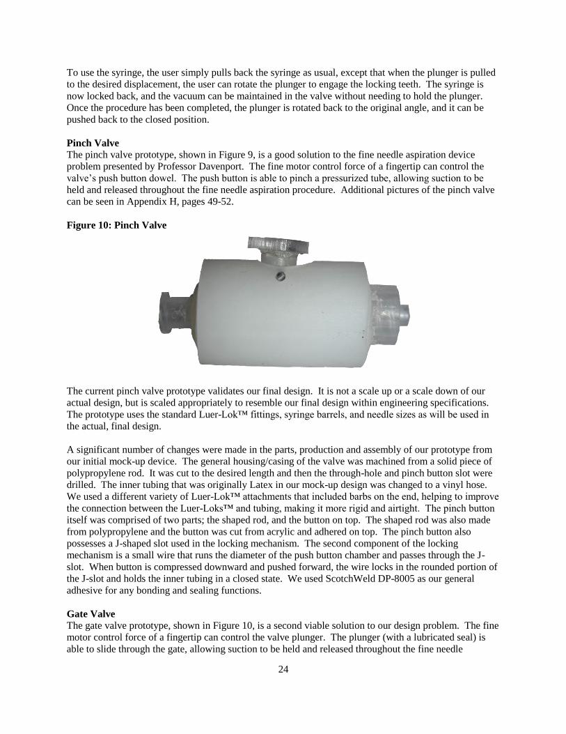
24
To use the syringe, the user simply pulls back the syringe as usual, except that when the plunger is pulled
to the desired displacement, the user can rotate the plunger to engage the locking teeth. The syringe is
now locked back, and the vacuum can be maintained in the valve without needing to hold the plunger.
Once the procedure has been completed, the plunger is rotated back to the original angle, and it can be
pushed back to the closed position.
Pinch Valve
The pinch valve prototype, shown in Figure 9, is a good solution to the fine needle aspiration device
problem presented by Professor Davenport. The fine motor control force of a fingertip can control the
valve‟s push button dowel. The push button is able to pinch a pressurized tube, allowing suction to be
held and released throughout the fine needle aspiration procedure. Additional pictures of the pinch valve
can be seen in Appendix H, pages 49-52.
Figure 10: Pinch Valve
The current pinch valve prototype validates our final design. It is not a scale up or a scale down of our
actual design, but is scaled appropriately to resemble our final design within engineering specifications.
The prototype uses the standard Luer-Lok™ fittings, syringe barrels, and needle sizes as will be used in
the actual, final design.
A significant number of changes were made in the parts, production and assembly of our prototype from
our initial mock-up device. The general housing/casing of the valve was machined from a solid piece of
polypropylene rod. It was cut to the desired length and then the through-hole and pinch button slot were
drilled. The inner tubing that was originally Latex in our mock-up design was changed to a vinyl hose.
We used a different variety of Luer-Lok™ attachments that included barbs on the end, helping to improve
the connection between the Luer-Loks™ and tubing, making it more rigid and airtight. The pinch button
itself was comprised of two parts; the shaped rod, and the button on top. The shaped rod was also made
from polypropylene and the button was cut from acrylic and adhered on top. The pinch button also
possesses a J-shaped slot used in the locking mechanism. The second component of the locking
mechanism is a small wire that runs the diameter of the push button chamber and passes through the J-
slot. When button is compressed downward and pushed forward, the wire locks in the rounded portion of
the J-slot and holds the inner tubing in a closed state. We used ScotchWeld DP-8005 as our general
adhesive for any bonding and sealing functions.
Gate Valve
The gate valve prototype, shown in Figure 10, is a second viable solution to our design problem. The fine
motor control force of a fingertip can control the valve plunger. The plunger (with a lubricated seal) is
able to slide through the gate, allowing suction to be held and released throughout the fine needle

25
aspiration procedure. Also, the current prototype has a saw-tooth, locking syringe plunger, as was used to
hold and release suction in the final design. Additional pictures of the gate valve can be found in
Appendix I, pages 53-56.
Figure 11: Gate Valve
The current gate valve prototype validates our final design. It is not a scale up or a scale down of our
actual design, but is scaled appropriately to resemble our final design within engineering specifications.
The prototype uses the standard Luer-Lok™ fittings, syringe barrels, and needle sizes as will be used in
the actual, final design.
A number of changes were made in the parts, production and assembly of our prototype from our initial
mock-up device. The general housing/casing of the valve was machined from a solid piece of
polypropylene rod. It was cut to the desired length and then the through-hole and gate plunger slot were
drilled. The gate plunger, also made from polypropylene rod, was machined with appropriately sized and
positioned grooves to help grip the seals to the plunger. To eliminate the use of latex in the device, we
replaced the old seals with Viton™ rubber. To keep the gate plunger moving more smoothly, we have
been adding an oil-based lubricant to the seals. We used ScotchWeld DP-8005 as our general adhesive
for any bonding, and sealing functions.
VALIDATION
Engineering Specifications vs. Prototype Parameters
As mentioned earlier in this report, the engineering specifications of our design project were the major
drivers of our design process. They were critical foundations upon which all of our concepts, designs,
and ideas were centered. Satisfying the engineering specifications, especially with our prototype designs,
would allow our team to validate the approach taken to solve our fine needle aspiration device design
problem. Additionally, some of the success of our prototypes will be evaluated on how well they satisfy
the desired design specifications.
Now that the prototyping stage is complete, we have had a chance to verify the engineering specifications
that were set earlier in the design process. Recall from earlier in the report that the pertinent engineering
design specifications were the device diameter, length, suction pressure, collection volume, activation

26
force and weight. The table below lists the engineering specifications as well as the device parameters for
our two possible prototype designs. Verification of the specification is marked in the right column.
Table 3: Validation of Prototypes to Engineering Specifications
Engineering
Specification
Target Prototype A
Pinch Valve
Prototype B
Gate Valve
Target
A
Satisfied?
B
Diameter ≤ 2.5 cm 2.5 cm 2.3 cm YES YES
Length 11.25-15 cm 15 cm 14.7 cm YES YES
Suction Pressure < 5 kPa 4.1 kPa* ≈ 0 kPa* YES YES
Collection Volume ≥ 0.04 cc ≥ 0.04 cc ≥ 0.04 cc YES YES
Activation Force < 20 N 11.6 N 36 N YES NO
Weight < 250 g 21.3 g 28.3 g YES YES
*These values were calculated, not measured.
Experiments Used to Verify Engineering Specifications
Laboratory testing similar to what was used to determine the original engineering specifications was
reused to determine the prototype specifications. In particular, device diameter was assumed as the
maximum outer diameter of the prototype and it was measured using a standard metric caliper. Similarly,
a measurement was taken with a standard metric ruler to determine the prototype length. Recall this
length was defined as the distance from male Luer-Lok™ tip on the front end of the device to the syringe
flange on the butt end of the device. Suction pressure is a specification of the prototypes that was
individually considered because of our difficulty in quantifying it. See the section below for our
procedure and method of calculation. Collection volume is directly related to suction pressure and was
determined each of the devices with a benchmarking test. Although this may not seem like the best way
to measure such a parameter, as long as adequate suction exists (and it does), we do not foresee collection
volume to be an issue. Finally, device weight was determined using a standard mass scale and included
all components of the design (needle, valve and syringe).
Engineering Specifications Discussion The measurement of the suction pressure parameter for each of the prototype designs was more of a
challenge than anticipated. Our team took a numerical and idealized approach to measure the suction
pressure. Specifically, we determined the volume of air that we could displace which each device
(included both the volume within the syringe and the valve), then used an ideal gas law (Boyle‟s law) to
determine the (negative) pressure that could be achieved. This approach assumed perfectly sealed devices
as well as pure air as our fluid medium, which may introduce some error in our pressure calculations, but
we believe the error would be insignificant.
Hinging upon the suction pressure parameter was the collection volume. To briefly recap, in order to
successfully collect tissue samples removed during a fine needle aspiration procedure, a suction pressure
of about five kilopascals is required; this being the upper limit. Based on the trial-and-error of our
prototypes, we anticipated that our general ballpark number for the suction pressure for each device was
more than sufficient to apply enough pressure to collect adequate sample during the procedure. As a
safety precaution, our team worked with a safety factor to make sure that the operator of the prototypes
has the option to increase suction as he or she sees fit. To supplement our calculations on the collection
volume, our team ran a benchmarking test on each of the valves. The benchmarking test consisted of
creating a vacuum of 10 cc volume within the chamber of a syringe with the each valve design, and then
testing the amount of water each syringe could collect. In each case, the collection of water was greater
than 9 cc, which by far exceeds our specified 0.04 cc collection volume.

27
Lastly, the activation force necessary to apply the suction pressure for each prototype was determined.
These measurements were completed using a scale from a University of Michigan Mechanical
Engineering lab. For each of the two valves, we anticipate that the activation force will be substantially
smaller for a device that would be mass produced. The prototypes that we constructed were somewhat
limited by our ability to manufacture precise tolerances within our machine shop. Specifically, for the
gate valve, we feel that an interface similar to the one that exists between the rubber seals on a plunger in
a current syringe could be integrated into our gate hole and plunger design. Such a change would
undoubtedly reduce the activation force substantially, accounting for the fact that our gate valve prototype
did not meet the activation force target at this point.
Why the Design Approach Works
The approach that our team of engineers used to solve our design problem was very systematic, yet
problem solving-oriented. First, by vigorously describing our design problem, our team was able to
largely grasp the design problem in its entirety. Understanding every aspect of a design problem allowed
our team to explore every possible solution to the problem. From this detailed problem description, our
team brainstormed in a non-stress environment, exploring every solution to the problem, even those
outside of the box. These ideas were then organized into categories by their solution type, and design
scoring matrixes were used to choose the best type of solution to our problem as well as the best device to
solve our problem. Stemming from these exercises, our team was left with three valve devices (ball, gate,
and pinch valves) for prototype mock-up verifications. At this stage, we wanted to make sure that the
design itself was indeed feasible to produce. This step proved to be fatal for the ball valve, and it was
dropped from our list. Our team of engineers has tried to consider every possible design in our approach
as well as verify the best resulting design solution. Consequently, we feel that our design approach was
planned, creative, and precautious in order to achieve success in our design problem.
MASS PRODUCTION MANUFACTURING
Our prototypes were built using stock materials that we machined down to their final shapes. We also
glued together a variety of purchased parts to create the final prototypes. If this design were to be
produced in large scale, the fabrication would be very different. In this section, we will discuss what
changes would need to be made to the designs for large scale manufacturing.
Using the CES Manufacturing Selector, we found that injection molding would be the best way to mass
produce the polypropylene valve bodies that we fabricated from rod stock. In our prototypes, we glued
polypropylene Luer-Loks™ to the ends of the valve bodies. In a mass production setting, these Luer-
Loks™ would be incorporated into the valve body, so it would all be molded in one shot. This would
eliminate the need for any adhesive bonding of parts.
The gate valve consists of a main body piece and the plunger piece. The body piece could be injection
molded in one piece. The plunger is essentially a rod with grooves in it. These grooves serve as seats for
the Viton™ tube that acts as a seal against the valve body. The grooved rod could also be injection
molded as a separate piece from the gate valve body. The Viton™ seals could be cut from a continuous
length of tube, and slipped over the plunger rod. This makes a total of two injection molded parts and
two parts cut from a continuous tube. The assembly would be the most labor-intensive part of the process
for the gate valve. The Viton™ seals would need to be slipped over the rod and into their grooves. This
could probably be done as an automated process. Our sponsor gave us a target of less than $3 per unit for
a disposable device. Based on the cost of a comparably sized syringe with a similar number of parts, we
believe that a price under $3 would be easily attainable, were the gate valve to be mass manufactured.

28
The pinch valve body could also be molded as a single piece. However, we do not know what the best
way to incorporate the flexible tube would be. The tube must run through the inside of the body, and be
sealed to the Luer-Lok™ on either end. The solution could be to make the valve body in two halves that
could snap together in the middle. The button, which was very difficult to manufacture in our machine
shop, could again be simply injection molded as a single piece, and could be made much more precisely
than we were able to achieve. The flexible vinyl tube and the wire lock could both be cut from
continuous rolls of material. This brings the part count for the pinch valve up to five, with three injection
molded parts. Again, the assembly would be the issue with mass production of this device.
The syringe lock would be a relatively easy device to build. The design is very similar to existing
syringes, and could be created simply by modifying the existing mold for the syringe plunger to include a
saw tooth pattern on the edge of one fin of the plunger. In our prototype, the wire lock was threaded
through a hole in the syringe body. In mass production, it would probably be more cost-effective to
incorporate the lock into the molded syringe body as a plastic ratchet edge. It would be fairly simple to
produce and would not require any more equipment than what syringe manufacturers already have.
PROJECT TIMELINE
Part of the ongoing planning component of our project included the upkeep of an active Gantt chart, used
to track team progress and keep us aware of upcoming deadlines. The Gantt chart also served as an
accountability tool for individual team members to complete project components for which they were
responsible for.
Mileposts for the Project
At the milepost of Design Review #2, we decided that the valve design was our first-choice (alpha)
concept design. From Design Review #2 until Design Review #3, our team was responsible for
thoroughly exploring the concept design for engineering feasibility and defining rigorous specifications
for it. If, anywhere along this process of verifying the validity of our valve design, we were to discover
that it was not a feasible design, then we would have explored one of our secondary concept designs, the
electrical linear actuator design or the push slider design.
At the milepost of Design Review #3, we had produced mock-ups of the pinch, gate, and ball valve
designs. We had decided that the pinch and gate valves were our first-choice designs. By Design Review
#4, our team had finalized many of the details of the pinch and gate valves, and had created two final
designs for the Design Expo. By the Expo, we had completed the fabrication of our prototypes, and
completed all of the auxiliary assignments to be turned in with the final report, such as the Design Expo
poster layout (Appendix J, page 57), materials selection assignments (Appendix K, pages 58-60),
environmental impact assignment (Appendix L, pages 61-68), process selection assignment (Appendix
M, pages 69-75) and the safety report (Appendix N, pages 76-109).
Summary of Completed Tasks since Concept Selection
In solidifying the feasibility of our alpha valve design after Design Review #2, several tasks were
completed. The first step in exploring this design space was to create mock-ups of our valve design. We
considered that our University of Michigan laboratory resources may not have been sufficient in
producing very small designs and that we may have needed to work with outside vendors to create mock-
ups of the designs. Therefore, we purchased parts from the Home Depot, Ace Hardware, McMaster-Carr,
and Cole-Parmer to create mock-up prototypes of the pinch, gate, and ball valves. These mock-up
prototypes allowed us to physically test our designs‟ quality. We met with Professor Davenport to survey
his opinion of the designs‟ functions and forms. The valve designs did not prove to be insufficient for
any reason, we did not need to make a mock-up of one of our secondary concept designs and repeat this

29
part of the process. Since these pinch valve and gate valve design mock-ups were approved by Professor
Davenport and appeared to meet our engineering specifications, we were able to move ahead in our
process.
After deciding on the appropriate concept designs to produce, based on our mock-ups, our next step was
to finalize all of the engineering specifications, in preparation for making the final design prototypes. We
used UniGraphics NX 5.0 CAD (Computer Aided Design) software to create orthographic and three-
dimensional views of the designs with specific dimensions [3].
In order to prepare our final prototypes, we needed to purchase additional parts that we did not already
have. After the parts were purchased and delivered, we worked in the ME machine shop to replicate our
pinch and gate valve mock-ups as polished, final prototypes for the Design Expo. After creating our final
prototypes and presenting them in Design Review #4, we worked to prepare our alpha prototype
presentations for the Design Expo.
While building our final prototypes, we were also working on key components for the final report. We
completed the documentation for the Safety Report as we bought parts and built mock-ups. Additionally,
we had to continually have our design approved for safety by Professor Im. We completed the Material
Selection Assignment (functional performance and environmental performance) using the CES
(Cambridge Engineering Selector) material selection software to confirm that the materials we used were
the optimal choices for the specifications of our final design. We also completed the Manufacturing
Process Selection Assignment, again using CES. Individually, we all completed an individual ethics
essay.
As has been the case all semester, we worked as a team on all of the tasks above (with the exception of
the individual ethics reports, of course). We collaborated to complete each task in our design process,
working together and exchanging ideas, rather than using a divide and conquer strategy.
Gantt Chart
To organize the milestones of our project into a neat and organized manner, the major and minor
deadlines of our fine needle aspiration project were organized into a Gantt chart. This tool allowed our
team to easily visualize progress, satisfy task deadlines on time, and assign future work to prevent
procrastination. See Appendix E on page 44 for our Gantt chart.
Budget
At the conclusion of our design process, we had spent a total of $174.96, well below the allotted budget
of $400. In addition to the parts we purchased, we used syringes and needles that Professor Davenport
supplied to our team free of cost. We estimated that the total value of these donated syringes was no
more than $10. We have also used force transducers and mass scales from the AutoLab laboratories at
the University of Michigan, provided free of cost, to take measurements for our engineering
specifications. All of the parts that were used in the final prototypes were purchased from McMaster-Carr
Supply Company. For the mock-ups and intermediate devices, we used parts bought from local hardware
stores and Luer-Lok™ connections purchased from Cole-Parmer Instrument Company.\
RECOMMENDATIONS
Although we did produce two working prototypes, the job of fabricating these devices was long and
arduous. We believe that our designs are well conceived and are an improvement over previous devices
for fine needle aspiration. Were someone to attempt to recreate our project, we recommend that they use
our design, although the fabrication process could be improved.

30
When we designed our gate valve, our goal was for the inside of the valve body to mimic the inside of a
syringe, such that the rubber seal effectively creates an airtight seal against the valve body, yet still slides
easily along the length of the tube. Naturally, the best way to recreate this functionality is to use the same
materials as used in a syringe. The syringe body is polypropylene, and the plunger seal is butyl rubber.
We used polypropylene in our valve bodies, but we were unable to obtain butyl rubber of the correct size
and shape to use in our prototypes. Instead, we used Viton™ tubing for our seals, which is firmer and
less elastic than butyl rubber. We recommend that butyl rubber be pursued as the seal to lower friction
and ensure an airtight seal. Also, the size and shape of the seals could be altered slightly to make the
device more compact and more easily held by the fingertips. Additionally, to further reduce friction, the
formula of the polypropylene could be altered. It is common practice to use additives in plastics to
enhance certain properties. It would be simple to incorporate a lubricating additive to the polypropylene
to lower the friction between the gate valve and the seals.
Our chief concern with the pinch valve was the locking mechanism. We struggled to fabricate the hole in
the button with the required level of precision. We recommend that anyone who pursues this device
further looks into better facilities for fabricating plastic parts. We used the equipment available in the ME
machine shop: drills, lathes, and saws. These tools are designed for metalworking and are too large and
lack the precision necessary for the fabrication of plastics. We regret not researching the plastics facilities
available at the University of Michigan, and recommend that they be researched before further work.
The syringe plunger could be improved by incorporating the locking feature into the syringe body. The
plunger itself is easy enough to produce, but our device uses a wire wrapped around the syringe body to
catch the saw teeth. It would be an improvement if some other method of retaining the saw teeth could be
developed and built into the syringe body; that would reduce assembly time and complexity of the part.
One simple solution would be a partial lid that covers a small sector of the circular area of the syringe
body. When a saw tooth is rotated over the lid, it would catch the edge and not be able to proceed
downward.
These are a few changes that could be made to the design and fabrication processes of the devices that
would lead to better quality and repeatability of the designs.
CONCLUSIONS
The current devices for performing fine needle aspirations do not meet doctors‟ needs as they perform this
procedure. The devices typically use a pistol grip that requires movement of the large muscle groups in
the hand and arm to maneuver the needle tip. Our sponsor, Professor Robertson Davenport, M.D., of the
University of Michigan Hospital‟s Department of Pathology, asked us to design a new device to allow
doctors to use the finger tips to position and activate the device. Using the fingertips allows for much
finer control over the positioning of the needle during the procedure, and also increases tactile feedback
from the tissue. That way, the doctor can more accurately direct the needle, and can also feel the
consistency of the tissue through which the needle is passing.
We carried out the steps of the standard design process, researching and defining the problem, then
defining the success criteria for the design and the engineering specifications. Then, through
brainstorming and some broadening of the design concepts, we developed a wide range of concepts to
fulfill our sponsor‟s request. We then went through the process of concept selection, narrowing the field
down to the most feasible concepts. The concept that emerged as the design to be pursued was a valve
design, which decouples the action of creating a vacuum in the syringe and the movement of the needle
tip. The vacuum is created in a syringe with a closed valve before the procedure begins, and the vacuum

31
is activated to the needle tip once it has been inserted into the skin. The device is held like a pen, and the
vacuum is activated with a single button press.
We developed two distinct valves that can be used in this procedure, a gate valve and a pinch valve. The
gate valve‟s design is more likely to be produced in a mass manufacturing setting since it can be injection
molded in two main pieces with two seals. The gate valve also has an advantage in the way it operates.
With the gate valve, the doctor does not need to remove the needle after the procedure to express the
sample. The pinch valve is simpler, but would be more difficult to manufacture, since it requires a
flexible piece inside of a rigid shell. All of the details of these devices can be found in the body of this
report. After developing the designs on paper, we fabricated prototypes using stock materials. The
prototypes serve as proofs of concept that the designs function the way we wanted, and working models
to show interested parties.
Both of our final valve prototypes meet the engineering requirements we set out to achieve at the
beginning of the design process (gate valve activation force aside; explanation in validation section on
page 26). More importantly, they satisfied the goals that Professor Davenport has asked us to achieve.
They can be easily held and manipulated with a single hand, and the vacuum can be activated or
deactivated with one finger. These devices mark a significant improvement over the existing options in
terms of fine motor control, tactile feedback, and needle stability.
ACKNOWLEDGEMENTS
We would like to thank and acknowledge the following individuals for their contributions throughout the
course of our project:
Professor Roberston Davenport, M.D.
Doctor Stewart Knoepp, M.D.
Professor Hong G. Im
Professor Steven Skerlos
Robert Coury
Marv Cressey
Daniel Johnson
Tom Bress
Max Bajcz

32
REFERENCES AND INFORMATION SOURCES
[1] Cameco Syringe Pistol / Gun from Omega. (2009). Medical & Healthcare Products Ltd. Retrieved
January 29, 2009, obtained from http://www.omegahealthcare.co.uk/medical_healthcare_products.htm.
[2] Knoepp, Stewart. Personal Interview. 23 Jan. 2009.
[3] Siemens PLM (2007). NX 5.0 [Computer Software]. Siemens AG, Plano, Texas.
[4] Tao, L. & Smith, J. W. (1999). Fine-Needle Aspiration Biopsy Using a Newly-Developed Pencil-Grip
Syringe Holder. Diagnostic Cytopathology, 20 (2). 99-104.
[5] Hut, P. K. H. Fine Needle Aspiration: Cytological Biopsy Technique. Retrieved January 29, 2009
from http://www.curamedical.nl.
[6] Bardagjy, J., Diffrient, N., & Tilley, A.R. (1991). Humanscale 1-9. London: The MIT Press.
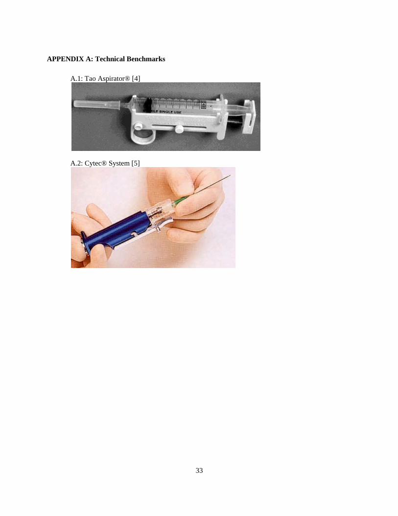
33
APPENDIX A: Technical Benchmarks
A.1: Tao Aspirator® [4]
A.2: Cytec® System [5]

34
APPENDIX B: Hand Strength Chart [6]

35
APPENDIX C: Concept Sketches
C.1 Valve Design
C.2 Electrical Linear Actuator
C.3a Push Slider Sketch 1

36
C.3b Push Slider Sketch 2
C.4 Direct Slider
C.5 Spring and Locking Slider
C.6 Spring Loaded Design

37
C.7 Lever Arm Design
C.8 Live Hinge Design
C.9 Rack and Pinion Design

38
C.10 Shoe Pump Design
C.11 Diaphragm Design

39
C.12 Ball Valve Design

40
C.13 Gate Valve Design

41
C.14 Pinch Valve Design
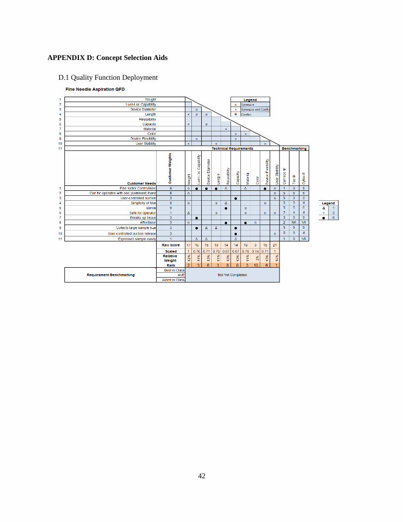
42
APPENDIX D: Concept Selection Aids
D.1 Quality Function Deployment

43
D.2: Design Scoring Matrix
D.3: Valve Scoring Matrix
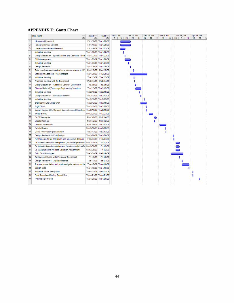
44
APPENDIX E: Gantt Chart

45
APPENDIX F: Bill of Materials Materials List
FINE NEEDLE ASPIRATION 20-Apr-09
Part # Part Name Qty Material Size Manuf. Process Function Cost
PINCH VALVE PROTOTYPE PARTS - Made
TEE, 1/2" BARB 1 NYLON
CUTTING PINCH VALVE MOCKUP HOUSING $1.29
8658K51 ROD 1 POLYPROPYLENE 1/4" x 2" CUTTING BUTTONS $5.92
TUBE, FLEXIBLE 1 VINYL 1/4" x 2" CUTTING BALL VALVE HOUSING $2.14
5234K71 TUBE, FLEXIBLE 1 LATEX 1/4" x 2" CUTTING PINCH VALVE TUBE $9.80
SYRINGE BARREL 1 POLYPROPYLENE 10cc CUTTING PINCH VALVE MOCKUP HOUSING
DISC 2 ACRYLIC 0.65"x0.093" CUTTING PROTOTYPE ENDCAPS $5.58
PINCH VALVE PROTOTYPE PARTS - Off-the-shelf
SEALANT 1 SILICONE
OFF THE SHELF SEALANT $3.98
EPOXY, PLASTIC 1
OFF THE SHELF GLUE $4.99
EW-45505-33 LUER-LOK, MALE, 1/8" HOSE BARB 1 NYLON
OFF THE SHELF NEEDLE CONNECTOR $6.00
EW-45502-04 LUER-LOK, FEMALE, 1/8" HOSE BARB 1 NYLON
OFF THE SHELF SYRINGE CONNECTOR $6.50
PINCH VALVE FINAL DESIGN PARTS - Made
8658K54 ROD 1 POLYPROPYLENE 3/4" x 2" CUTTING, DRILLING PINCH VALVE PROTOTYPE BODY $14.08
5234K71 TUBE, FLEXIBLE 1 LATEX 1/4" x 1" CUTTING PINCH VALVE TUBE $9.80
8658K51 ROD 1 POLYPROPYLENE 1/4" x 1" CUTTING, MILLING PUSH-ROD $5.92
PINCH VALVE FINAL DESIGN PARTS - Off-the-shelf
7467A32 ADHESIVE, SCOTCHWELD DP-8005 1
OFF THE SHELF ADHESIVE $23.59
51525K143 LUER-LOK, MALE, 1/8" HOSE BARB 1 POLYPROPYLENE
OFF THE SHELF NEEDLE CONNECTOR $4.09
51525K293 LUER-LOK, FEMALE, 1/8" HOSE BARB 1 POLYPROPYLENE
OFF THE SHELF SYRINGE CONNECTOR $3.69
GATE VALVE PROTOTYPE PARTS - Made
8658K51 ROD 1 POLYPROPYLENE 1/4" x 8'
PLUNGER ROD $5.92
5234K71 TUBE, FLEXIBLE 1 LATEX 1/4" x 1" CUTTING PLUNGER GASKETS $9.80
SYRINGE BARREL 1 POLYPROPYLENE 10cc CUTTING GATE VALVE MOCKUP HOUSING
SYRINGE BARREL 1 POLYPROPYLENE 3cc CUTTING GATE VALVE PLUNGER TUBE
SYRINGE BARREL 1 POLYPROPYLENE 1cc CUTTING GATE VALVE INNER PASSAGE
DISC 2 ACRYLIC 0.65"x0.093" CUTTING PROTOTYPE ENDCAPS $5.58
GATE VALVE PROTOTYPE PARTS - Off-the-shelf
RESIN, BONDO 1 FIBERGLASS 1 pt OFF THE SHELF GAP FILLER IN GATE PROTOTYPES $9.49
EPOXY, PLASTIC 1
OFF THE SHELF GLUE $4.99
EW-45505-33 LUER-LOK, MALE, 1/8" HOSE BARB 1 NYLON
OFF THE SHELF NEEDLE CONNECTOR $6.00
EW-45502-04 LUER-LOK, FEMALE, 1/8" HOSE BARB 1 NYLON
OFF THE SHELF SYRINGE CONNECTOR $6.50
GATE VALVE FINAL DESIGN PARTS - Made
8658K55 ROD 1 POLYPROPYLENE 3/4" x 2" CUTTING, DRILLING GATE VALVE PROTOTYPE BODY $2.71
8658K51 ROD 1 POLYPROPYLENE 1/4" x 8'
PLUNGER ROD $5.92
5234K71 TUBE, FLEXIBLE 1 LATEX 1/4" x 1" CUTTING PLUNGER GASKETS $9.80
GATE VALVE FINAL DESIGN PARTS - Off-the-shelf
7467A32 ADHESIVE, SCOTCHWELD DP-8005 1
OFF THE SHELF ADHESIVE $23.59
51525K143 LUER-LOK, MALE, 1/8" HOSE BARB 1 POLYPROPYLENE
OFF THE SHELF NEEDLE CONNECTOR $4.09
51525K293 LUER-LOK, FEMALE, 1/8" HOSE BARB 1 POLYPROPYLENE
OFF THE SHELF SYRINGE CONNECTOR $3.69
BALL VALVE PROTOTYPE PARTS - Made
TUBE, FLEXIBLE 1 VINYL 1/4" x 10' CUTTING PINCH VALVE PROTOTYPE TUBE $4.38
WASHER 1 RUBBER
CUTTING BALL VALVE GASKET $2.96
STOPPER 1 RUBBER
DRILLING BALL VALVE GASKET $0.80
BALL VALVE PROTOTYPE PARTS - Off-the-shelf
BALL BEARING 2 STEEL 5/16" OFF THE SHELF BALL VALVE $0.60
BALL BEARING 2 STEEL 1/4" OFF THE SHELF BALL VALVE $0.54
BALL BEARING 2 STEEL 3/16" OFF THE SHELF BALL VALVE $0.34
EPOXY, PLASTIC 1
OFF THE SHELF GLUE $4.99
SEALANT 1 SILICONE
OFF THE SHELF SEALANT $3.98
SYRINGE LOCK PROTOTYPE PARTS - Made
WIRE 1 GALVANIZED STEEL 16GA x 3" CUTTING SYRINGE LOCK SPRING $6.29
SYRINGE # POLYPROPYLENE 10cc CUTTING MODIFIED SYRINGE TO ACCEPT LOCK
MISCELLANEOUS
PIPE 1 PVC 1/2" x 10'
MISCELLANEOUS HOUSING $2.29
PLASTI-DIP 1
SEALANT $5.98

46
APPENDIX G: Final Prototype Drafting [5]
G.1 Gate Valve Design
G.2a Gate Valve Dowel Design

47
G.2b Gate Valve Dowel Design
G.3 Pinch Valve Design
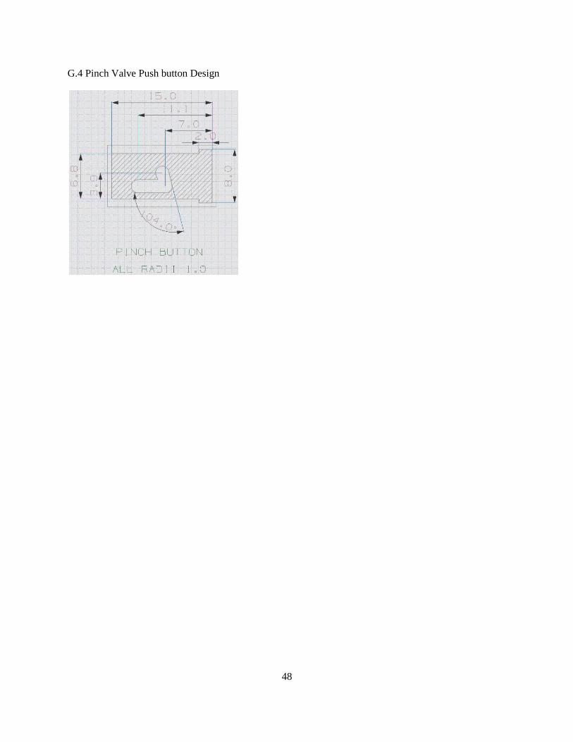
48
G.4 Pinch Valve Push button Design

49
APPENDIX H: Pinch Valve Operation and Procedural Instructions
Step 1: Locate needle and the male
Luer-Lok™ of the pinch valve
casing
Step 2: Attach needle to the male
Luer-Lok™ of the pinch valve
casing by inserting and
turning clockwise
Step 3: Attach syringe to opposite
end of the pinch valve
casing by inserting and
turning clockwise

50
Step 4: Close the valve by pushing down
on the push button and lock the
button by pulling back on the button
in the pushed position
Step 5: Now that the valve is sealed, to create a
vacuum in the sryinge barrel:
1. Twist the syringe plunger
counterclockwise
2. Pull back to the desired suction
level
3. Twist the plunger clockwise to
lock the plunger within a
sawtooth slot.
Step 6: Device is ready for
procedure.
1 2 3
1 2 3

51
Step 7: Insert needle into lump and
release lock to apply vaccum
to the needle tip by pressing
down and pushing forward on
the push button then releasing.
Step 8: After sufficient amount of
tissue cells are collected,
deactivate vaccum (before
removing needle) by pressing
and locking the button as in
step 4.
Step 9: Remove needle from the lump.

52
Step 10: Remove needle containting
tissue sample from valve casing
by twisting counter clockwise.
Step 11: Connect needle to another
syringe to express tissue onto
slide.

53
APPENDIX I: Gate Valve Operation and Procedural Instructions
Step 1: Locate needle and the male
Luer-Lok™ of the gate valve
casing
Step 2: Attach needle to the male
Luer-Lok™ of the gate valve
casing by inserting and
turning clockwise
Step 3: Attach syringe to opposite
end of the gate valve
casing by inserting and
turning clockwise

54
Step 4: Gate valve packaged in sealed
position. To create a vacuum in the
sryinge barrel:
1. Twist the syringe plunger
counterclockwise
2. Pull back to the desired suction
level
3. Twist the plunger clockwise to
lock the plunger within a
sawtooth slot.
Step 5: Device is ready for procedure.
Step 6: Insert needle into lump.
Two lines exposed in
initial (sealed position)
1 2 3

55
Step 7: Activate vacuum to needle tip
by pushing gate plunger to middle
position (second line).
Step 8: After sufficient amount of
tissue cells are collected,
deactivate vaccum (before
removing needle) by pressing
gate valve button entirely down.
Step 9: Remove needle from the lump.
Open position
shown, middle line
aligned with valve
top

56
\
Step 10: Unlock plunger to prepare
for tissue extraction by twisting
plunger clockwise.
Step 11: Flip gate valve 180 degrees
and return gate plunger to
middle position by pushing
the exposed button (uncapped
side of plunger) until it is
flush with the bottom of the
valve casing
Step 12: Express tissue sample onto
a slide for analysis by forcing
plunger down.

57
APPENDIX J: Design Expo Poster

58
APPENDIX K: Materials Functional Performance
Materials Selection Assignment
Functional Performance
Project 4: Fine Needle Aspiration
Flexible tube for pinch valve
Function: This flexible tube, inside of the pinch valve casing, connects between the syringe needle and
the syringe tip. It serves as a flexible passageway for air and tissue samples in the valve. By
pinching/creasing the flexible tube with the user-controlled pinch valve button, the sealed, flexible tube
holds and releases air pressure from the syringe.
Objective: minimize cost (must be below $3 per total design unit)
Constraints: must flex to seal (~35A durometer)
Material Indices:
Since we cannot define the durometer in terms of other parameters, we were not able to define
material indices for the flexible tube for the pinch valve. We decided to simply limit our search to
elastomers in the durometer range of Shore 30A-40A. The proof-of-concept we built used a latex tube of
35A, which worked very well, so we tried to match that (while avoiding latex for allergy issues).
The objective is to minimize cost, so to select our first five options, we looked at the five cheapest
materials in the range of 30A-40A.
CES Top 5 Material Choices: 1: PVC-elastomer
2: Butadiene rubber (nitrile)
Softest readily available grade of nitrile tube is about 60A
3: Ethylene propylene diene (EPDM)
Softest readily available grade of EPDM tube is about 60A
4: SIS (Styrene Isoprene Styrene)
Not readily available
5: Butyl Rubber
Expensive in tube form
Final Choice: PVC
PVC is readily available, low cost, and meets the hardness/durometer requirement. Although CES
rated Butadiene Rubber (nitrile) and Ethylene Propylene Diene (EPDM) within the 30-40 A hardness
range, they were only available for purchase at 60 A hardness in reality. The Styrene Isoprene Styrene
(SIS) is not readily available. The Butyl Rubber highly exceeds our minimal cost objective. According to
CES, PVC is our best option, and it also is available on McMaster in the right size and hardness.

59
Gate Valve Casing
Function: This valve casing/structure connects between the syringe needle and the syringe tip. It serves
as a strong, rigid structure to withstand user forces and internal pressures.
Objective: minimize cost (must be below $3 per total design unit)
Constraints: maximum mass specification =250 g
fixed volume = 0.0000135 m^3
minimum ultimate tensile strength = 450 kPa
Material Indices: ↑Material Index = ↑Performance
Cost = V*c (V = volume, c = unit cost)
m = ρ*V (m = mass, ρ = density)
Eliminated free variables: V
Material Indices: M = ρ/c (to be maximized)
Cost = m*(c/ρ)
We considered materials
between 30A and 40A

60
CES Top 5 Material Choices: 1: Polypropylene
Our first-choice material
2: Polybutylene (PB)
Only bonding adhesives, manifolds, and tube fittings available
3: Polymethylpentene (PMP)
Only film readily available; would have to special order
4: Thermoplastic Polyolefin Elastomer (PP+EP(D)M)
Only plastic welding rod available
5: Ethyl Methyl Acrylate (EMA)
Only available by special order overseas
Final Choice: Polypropylene is our first choice because it meets all of our CES objectives and
constraints, and is readily available to order in the rod form we need. Even if we were to order
Polymethylpentene (PMP) in its available film form, Thermoplastic Polyolefin Elastomer (PP+ER(D)M)
in its available plastic welding rod form, or Polybutylene (PB) in its available bonding
adhesive/manifold/tube fitting form, we couldn‟t machine the material to our desired form. It was
possible for us to special order a Polymethylpentene (PMP) rod or an Ethyl Methyl Acrylate (EMA) rod,
but the added cost and time of shipping these special orders from overseas companies was not worth it.
Polypropylene will do the job.
The best options are to the
upper left in the graph
We would like to minimize density as
a secondary objective, so we look at
the least dense of the viable options

61
APPENDIX L: Environmental Impact
Materials Selection Assignment
Environmental Performance
Project 4: Fine Needle Aspiration
Flexible tube for pinch valve
1. Materials Considered: Polyvinylchloride (PVC) (Shore 35a)
Ethylene Propylene Diene M (EPDM)
2. Determination of Mass in Final Design:
Determine the volume of the tubing necessary using geometry
Determine the density of each material using Cambridge Engineering Selector
Multiply volume by density of selected materials to determine mass
Volume of tubing needed: ∀ = 𝜋 𝐷𝑂
2
2− 𝜋
𝐷𝐼
2
2
× 𝐿
∀ = 𝜋 1
4
2
2
− 𝜋 1
8
2
2
× 1.05314961 𝑖𝑛3
` ∀ = 0.0387723 𝑖𝑛3
Density of Polyvinylchloride (PVC) (Shore 35a) : 𝜌 = 0.03955 𝑙𝑏 𝑖𝑛3
Density of Ethylene Propylene Diene M (EPDM): 𝜌 = 0.03145 𝑙𝑏 𝑖𝑛3
Mass of Polyvinylchloride (PVC) (Shore 35a) tubing:
` 𝑚𝑎𝑠𝑠 = 𝜌 × ∀
𝑚𝑎𝑠𝑠 = 0.03955 𝑙𝑏𝑖𝑛3 × 0.0387723 𝑖𝑛3
𝑚𝑎𝑠𝑠 = 0.001533 𝑙𝑏 ≅ 0.0006954 𝑘𝑔
Mass of Ethylene Propylene Diene M (EPDM):
𝑚𝑎𝑠𝑠 = 𝜌 × ∀
𝑚𝑎𝑠𝑠 = 0.03145 𝑙𝑏 𝑖𝑛3 × 0.0387723 𝑖𝑛3
𝑚𝑎𝑠𝑠 = 0.0012194 𝑙𝑏 ≅ 0.000553 𝑘𝑔
3. Corresponding Materials in SimaPro
Material Polyvinylchloride (PVC)
SimaPro Material: PVC film E
Ethylene Propylene Diene M (EPDM)
SimaPro Material: EPDM rubber ETH S
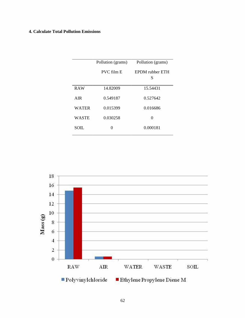
62
4. Calculate Total Pollution Emissions
Pollution (grams)
PVC film E
Pollution (grams)
EPDM rubber ETH
S
RAW 14.82009 15.54431
AIR 0.549187 0.527642
WATER 0.015399 0.016686
WASTE 0.030258 0
SOIL 0 0.000181

63
Carcinogens Resp. Organics
Resp. Inorganics
Ozone Layer Ecotoxicity Acidification Land Use Minerals Climate
Change Radiation
%
Human Health Ecosystem Quality Resources

64
5. Determine which material is more environmentally damaging
The EcoIndicator 99 damage classification reveals that using a Polyvinylchloride film E tubing
results in fewer grams of damaging effects on the environment compared to that of the Ethylene
Propylene Diene M rubber ETH S. Total mass of damage to the environment caused by Polypropylene
totaled 15.4 grams, compared to 16 grams caused by Propylene Diene M rubber ETH S. The damage
cause by Polyvinylchloride film E is focused primarily on raw and air pollutants. For the air, water, and
waste categories, Polyvinylchloride film E was more damaging than the Ethylene Propylene Diene M
rubber ETH S, but the amount of pollution was quite insignificant compared to raw pollution. Ethylene
Propylene Diene M rubber ETH S was more damaging in the raw and soil categories.
Based on the EI99 point values, the Human Health is the most notable and important meta-category,
followed by Resources and then Ecosystem Quality. For both materials, Human Health has point values
approximately two to six times greater that of Resources and ten to twenty times that of Ecosystem
Quality.
6. Since the application of both materials is for a disposable device, each will have the same lifecycle.
Because of this there is no reason to change the current evaluation and EPDM is still considered the most
environmentally unfriendly material.
EPDM rubber ETH S PVC film E
mPt

65
Casing for Gate Valve
1. Materials Considered: Polyvinylchloride (PVC)
Polybutylene
2. Determination of Mass in Final Design:
Computationally determine the volume of the casing using UGS NX 5.0
Determine the density of each material using Cambridge Engineering Selector
Multiply volume by density of selected materials to determine mass
Volume of tubing needed: ∀ = 0.827209 𝑖𝑛3
Density of Polyvinylchloride (PVC): 𝜌 = 0.03252315 𝑙𝑏𝑖𝑛3
Density of Polybutylene: 𝜌 = 0.03235 𝑙𝑏𝑖𝑛3
Mass of Polyvinylchloride (PVC) tubing: 𝑚𝑎𝑠𝑠 = 𝜌 × ∀
𝑚𝑎𝑠𝑠 = 0.03252315 𝑙𝑏𝑖𝑛3 × 0.827209 𝑖𝑛3
𝑚𝑎𝑠𝑠 = 0.026903 𝑙𝑏 ≅ 0.012203 𝑘𝑔
Mass of Polybutylene:
𝑚𝑎𝑠𝑠 = 𝜌 × ∀
𝑚𝑎𝑠𝑠 = 0.03235 𝑙𝑏𝑖𝑛3 × 0.827209 𝑖𝑛3
𝑚𝑎𝑠𝑠 = 0.0267602 𝑙𝑏 ≅ 0.0121382 𝑘𝑔
3. Corresponding Materials in SimaPro
Material: Polyvinylchloride (PVC)
SimaPro Material: PVC I
Material: Polybutylene
SimaPro Material: PB I
4. Calculate Total Pollution Emissions
Pollution (grams)
PVC I
Pollution (grams)
PB I
RAW 698.8253 869.3065
AIR 49.66145 13.94374
WATER 0.024542 0.073343
WASTE 2.053337 408.035
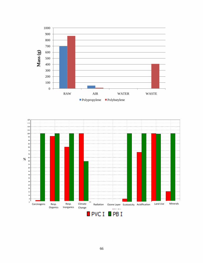
66
0
100
200
300
400
500
600
700
800
900
1000
RAW AIR WATER WASTE
Ma
ss (
g)
Polypropylene Polybutylene
Carcinogens Resp. Organics
Resp. Inorganics
Ozone Layer Ecotoxicity Acidification Land Use Minerals Climate
Change Radiation
%

67
Human Health Ecosystem Quality Resources
PVC 1 PB I
mPt

68
5. The EcoIndicator 99 damage assessment indicates that Polypropylene is less harmful to the
environment by generating less pollution than amount created by the Polybutylene. Specifically the
Polypropylene generates a totally of approximately 750 g of pollution, while the Polybutylene generates
1290 g. The major source of the pollution for both materials comes from raw state pollutants; however
the Polybutylene produces a rather significant quantity of waste pollutants as well. The only category
where Polypropylene generates more waste than the Polybutylene is air pollutants, however these
pollutants account for only a small percentage of the total pollution.
Based on the EI99 point values, it is rather obvious that Human Health is the most notable and important
meta-category. For both materials, Human Health has point values approximately ten times greater than
Eco-system Quality and ten to one hundred times that of Resources.
6. Since the application of both materials is for a disposable device, each will have the same full life
cycle. Because of this there is the initial material assessment remains unchanged and Polybutylene is still
considered the most environmentally unfriendly material.

69
APPENDIX M: Process Selection Assignment
Process Selection Assignment
Project 4: Fine Needle Aspiration
We assumed that a batch size of 10,000 – 100,000 units of our Fine Needle Aspiration device will be
useful to society. The best manufacturing process for the PVC flexible tube for the pinch valve was
polymer extrusion. The best manufacturing process for the polypropylene valve casing for the gate valve
was injection molding. These “best” processes were chosen using the CES Manufacturing Selector,
comparing legitimate values for mass range, section thickness range, tolerance range, and economic batch
size. The graphs below (CES printouts) justify these choices.
Flexible Tube—polymer extrusion
Since this is a piece to be produced, it is a primary shaping process. We defined the tolerance for the tube
radius to be 0.02 – 0.0055 in. This number is somewhat arbitrary, since the tube is flexible, and will
stretch if it is the wrong size, but for the sake of eliminating processes with high or low (and expensive)
tolerances, we chose the above range, shown as a box on the graph below.

70
Next, we defined the range of section thickness, which in this case is the wall thickness of the tube,
0.0625 in. Including a tolerance of 0.02 in, the range of section thickness becomes 0.0425 – 0.0825 in,
shown as a box on the chart below. Also, the part is a circular prismatic, which is reflected on the chart as
being on the right half of the chart.
Next, since the part is a short tube of constant diameter, it makes sense to produce as a continuous process
and cut the continuous tube to the correct length. Therefore, we added a limit stage to the CES selection
template that limited the processes to only continuous processes.
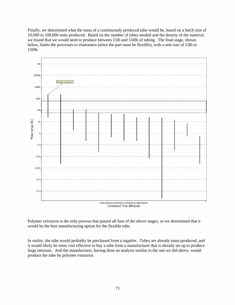
71
Finally, we determined what the mass of a continuously produced tube would be, based on a batch size of
10,000 to 100,000 units produced. Based on the number of tubes needed and the density of the material,
we found that we would need to produce between 15lb and 150lb of tubing. The final stage, shown
below, limits the processes to elastomers (since the part must be flexible), with a unit size of 15lb to
150lb.
Polymer extrusion is the only process that passed all four of the above stages, so we determined that it
would be the best manufacturing option for the flexible tube.
In reality, the tube would probably be purchased from a supplier. Tubes are already mass-produced, and
it would likely be more cost effective to buy a tube from a manufacturer that is already set up to produce
large amounts. And the manufacturer, having done an analysis similar to the one we did above, would
produce the tube by polymer extrusion.

72
Valve Casing – Injection molding
Again, the valve casing needs to be produced from some type of material stock, so it is a primary process.
To determine the tolerance for the part, we looked to the sections of the casing that would need to be most
precise, which are the Luer tips. According to ISO 594-1 (1986) for a 6% Luer-Lok standard conical
fitting, the diameter tolerance for semi-rigid material is given as 0.102mm, which equals 0.004 in. We
used a range of 0.003 – 0.005 in, as shown by the box below.

73
The part is a 3-D hollow part (a tube with a perpendicular hole), and the thickness ranges from
0.25 – 0.5 in. We displayed this range of thicknesses on the chart below as a box.

74
Next, we defined the material as a thermoplastic (x-axis of the chart below) and calculated the mass for
each part, based on its volume and the density of polypropylene, our chosen material. The mass range is
0.03-0.06 lb per unit, accounting for potential variations in the design to optimize mass manufacturing.
This range is boxed on the chart below.
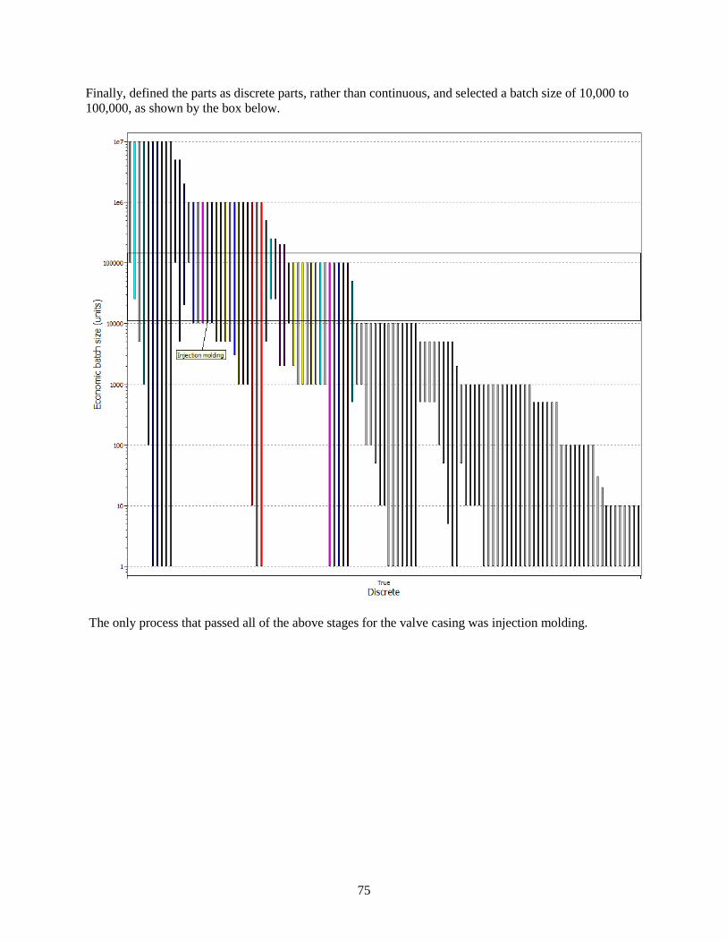
75
Finally, defined the parts as discrete parts, rather than continuous, and selected a batch size of 10,000 to
100,000, as shown by the box below.
The only process that passed all of the above stages for the valve casing was injection molding.

76
APPENDIX N: Safety Report
4 4/21/2009
A
Fine Needle Aspiration Device
Nathan Brown, Mary Kay DuBay, Jeff Otto, Joel Van Sloten
nathanab, mkdubay, jmotto, javs
Hong G. Im

77
1 EXECUTIVE SUMMARY This report covers the safety considerations for the design, manufacturing, and use of the devices designed by ME 450 Team 4. Experimental Plans Prior to Design Completion We will perform some very basic measurements on existing devices and equipment for fine needle aspiration to give us a baseline against which we can compare our final designs. The design process will be mostly completed through experimental testing of proof-of-concept devices and comparing the performance of those mock-ups to the desired outcome. Design Elements This report contains a list of all purchased materials for the project and an FMEA matrix for all of the components used in the final design. A DesignSafe report is included for each of the syringe, gate valve, pinch valve, and the device assembly. The major risks for each component are addressed with what preventative measures we have taken to eliminate those risks, as well as the measures we think will reduce risk in the use of the device. The CAD drawings for each designed component are included as well.
Manufacturing and Assembly Elements The majority of the manufacturing undertaken for the project will be cutting, drilling, and joining. The processes that required each type of machining are described in this report. Since most of the parts are plastics, the machining feeds and speeds are flexible, and the safety concerns are not as great as if the parts had been metal. The assembly issues will be intensified because of the small and precise nature of the parts required for the design.
Design Testing and Validation The design validation will happen step by step as we proceed through different stages and test individual aspects of the valves along the way. Most of these tests will not be quantitative as much as qualitative. To ensure that our engineering specifications are met, we will measure various physical properties of the devices.

78
2 EXPERIMENTATION PLANS PRIOR TO DESIGN COMPLETION The first thing we will test is the current setup used by doctors to perform fine needle aspirations. The current equipment is typically a 10cc syringe with a needle on the tip, held by a pistol-grip type syringe holder. We will begin by testing the force required to pull back on the syringe plunger in a 10cc syringe. We have contacted Tom Bress of the ME 395/495 labs, who has agreed to help us perform these experiments. We also would like to compare those results to the forces required to pull back the plunger on smaller syringes, such as a 3cc and 1cc syringe. These force measurements will show us what our target value is for activation force on our device. Ideally, we could make the activation force less than what already exists in the current setup. Since the device will ultimately be controlled with the fingertips, the activation force will be important. We do not foresee any safety risks in the measurement of the mass, dimensions, and force required to pull back a syringe. 3 PURCHASED COMPONENT AND MATERIAL INVENTORY Appendix A is a list of all the materials purchased for the project. Some will be used in building mock-ups and proof-of-concepts, and some will be used for the final prototypes. The materials are organized by their application, and each includes a description of its final use. None of these materials are inherently dangerous in their handling or use, unless used inappropriately. The only components that could be considered hazardous are the ScotchWeld DP-8005 adhesive and the fiberglass resin, both of which need to be used in a well-ventilated area, as it has fairly volatile fumes. The plastic epoxy and the silicone sealant should be well-ventilated as well, although they do not pose a threat. FMEA Analysis Results We performed an FMEA analysis on each of the purchased components to be used in the final prototypes. The table we used for the FMEA is shown in Appendix B. The FMEA results showed that the components that were most likely to cause a failure or safety hazard are the Viton tube in the gate valve and the PVC tube in the pinch valve. These, not surprisingly, are the only flexible parts in the either of the designs. They are the most likely to cause an issue because the both relate directly to the functional performance of the devices, and they also are the primary defense in ensuring that blood does not leak from the valves. The Viton tube in the gate valve serves as the seal that slides in the valve, allowing pressure to reach the needle or blocking it. If it fails, the valve will not hold pressure, and will not function correctly. To mitigate this issue, we have decided that it would be best to test each valve before shipping in a production setting. This testing could ensure that no valves with bad seals would go out. Since it is easy enough for us to simply look at the seals and determine whether they are damaged, we do not foresee and safety or failure issues for our prototype seal. The PVC tube in the pinch valve is the vessel through which the vacuum flows, allowing the vacuum to reach the needle tip. The tube is pinched by a rounded rod, sealing off the passage and not allowing vacuum to pass. If the rod should tear the tube, the valve would not hold pressure. If the sample of tissue was already collected at the time of tearing, some blood could exit through the failure in the tube, and the operator could be exposed to the blood. We can ensure in our prototype that the tube is intact by inspecting it before installation. However, once the procedure is in progress, an operator would have no indication that the tube had ruptured, which would lead to a test that did not collect any sample.

79
4 CAD DRAWINGS AND DESIGNSAFE ANALYSIS
Pinch Valve

80
Pinch Valve Button Detail

81
Gate Valve

82
Gate Valve Rod Details

83
DesignSafe Analysis Our analysis with DesignSafe shows that the highest safety risks are related to proper use. For the assembly as a whole, the highest risks were from mechanical failure of the device, and the potential for contact with blood-borne disease. Both valve designs should not experience mechanical failure in normal use. Therefore, if they were to actually fail, it would be due to improper use, if the devices were abused or used in another way than their intended use. The best way to ensure that abuse doesn’t happen is to make sure that the users understand the proper way to employ the device. This is standard training, and could be included in the form of an instruction booklet, or even a diagram showing how to correctly operate the devices. The other issue is that of blood-borne disease. This could happen if the seals or the flexible tube failed, depending on the valve type. In both cases, there is a small chance that blood could seep or drip out of the valve after the seal was ruptured. In either case, the user would be protected from any disease by wearing the appropriate equipment. Gloves are standard for doctors anyway, and would prevent their hands from coming in direct contact with patient blood. Also, respiratory masks are readily available in hospitals, so if the doctor wishes to protect himself further, that is always an option. The full DesignSafe reports can be found in Appendix C. 5 MANUFACTURING PROCESSES This section lists the manufacturing procedure for each mock-up and for each final prototype. The process is listed with the part to which it applies. Manufacturing Procedure List—Mock-Ups Pinch Valve 1. Size and cut vinyl tubing (1/2 x 0.170) 2. Cut nylon tee to size 3. Trim off male and female luer lock (with cone) from a syringe 4. Cut two body syringe parts to size a. Trim circular hole for tee top 5. Feed tube through tee 6. Seal tube to luer lock connections with silicon 7. Attach body to luer lok parts with plastic epoxy 8. Attach center body to body interface with plastic epoxy Gate Valve 1. Cut syringe 10cc syringe and 1cc syringe to desired valve length 2. Insert 1cc syringe into 10cc syringe, center and fill void with Fiberglass Resin 3. Cut slot for gate valve 4. Cut out gate from acrylic sheet or dowel 5. Trim hole in sheet or dowel 6. Coat gate valve with Plasti Dip 7. Insert into slot and troubleshoot

84
Ball Valve 1. Cut vinyl tubing (5/8 x 1/2) to desired length 2. Machine rubber cork to correct outer diameter and inner shape 3. Attach rubber cork to inside of vinyl tubing with adhesive 4. Attach tubing to male Luer lock with adhesive 5. Attach spring to ball bearing (solder?) 6. Attach opposite edge of spring to Luer lock 7. Attach other Luer lock to vinyl tubing 8. Troubleshoot We will assemble all components in the ME machine shop, as we do not have appropriate machines and tools to assemble the mock-ups on our own. Manufacturing Procedure List—Final Prototypes Pinch Valve 1. Cut a piece of ¾” polypropylene cylinder, 30.8mm long 2. Drill through length of ¾” polypropylene cylinder, 7.5mm diameter (500 RPM drill) 3. Drill through length of ¾” polypropylene cylinder, 12mm diameter , 2mm deep (500 RPM drill) for luer-loks 4. Drill through diameter of ¾” polypropylene cylinder, 6.0mm diameter, 21mm deep (500 RPM drill) 5. Cut vinyl tubing (½”x 0.170”) 6. Run vinyl tubing through length of ¾” polypropylene cylinder 7. Seal male and female luer-loks to end of vinyl tube with Scotch-Weld DP8005 8. Seal ¾” polypropylene cylinder ends to luer-lok connection with Scotch-Weld DP8005 Pinch Valve Push Button 9. Cut 16 gauge galvanized steel wire, 10mm long 10. Drill hole through ¾” polypropylene cylinder to run steel wire through, 1/16” diameter 11. Cut 6.8mm polypropylene cylinder, 20mm long 12. Drill J-shape out of 6.8mm polypropylene cylinder 13. Run steel wire through one ¾” polypropylene cylinder hole, through the J-shape of 6.8mm polypropylene cylinder, through other ¾” polypropylene cylinder to secure push button 14. Cut 8mm diameter button cap, 2mm deep 15. Adhere 8mm diameter button cap to 6.8mm polypropylene cylinder with Scotch-Weld DP8005 Gate Valve 1. Cut a piece of 1” polypropylene cylinder, 30.6mm long 2. Drill through length of 1” polypropylene cylinder, 1.6mm diameter (500 RPM drill) 3. Drill through length of 1” polypropylene cylinder, 12mm diameter , 2mm deep (500 RPM drill) for luer-loks 4. Drill through diameter of 1” polypropylene cylinder, 6.8mm diameter, (500 RPM drill) 5. Seal 1” polypropylene cylinder ends to luer-lok connection with Scotch-Weld DP8005

85
Gate Valve Button 6. Cut 2 pieces of ¼” OD, 1/8” ID Viton rubber, 2.5mm long and 4.5mm long 7. Cut 6.8mm diameter polypropylene cylinder, 30.7mm long 8. Etch out holders on 6.8mm diameter polypropylene cylinder for Viton rubber seals 9. Slide Viton rubber seals onto 6.8mm diameter polypropylene cylinder 10. Insert gate valve button into through hole of 1” polypropylene cylinder with Banana Boat dark tanning oil lubrication 11. Cut 8mm diameter button cap, 2mm deep 12. Adhere 8mm diameter button cap to 6.8mm polypropylene cylinder with Scotch-Weld DP8005 Syringe Plunger 1. Remove standard syringe plunger from syringe barrel 2. Carve a saw-tooth edge out of one syringe plunger face with an Exact-o knife 3. Drill two 1/16” holes out of syringe barrel flange 4. Run 16 gauge galvanized steel through flange holes 5. Re-insert saw-tooth syringe plunger into syringe barrel We will assemble all components in the ME machine shop, as appropriate machines and tools to assemble the prototypes are not available elsewhere. The cutting processes listed above are either cutting on a bandsaw or using a hobby knife. For the larger plastic parts that need to be cut to length, the pieces will be cut on the bandsaw with a speed of about 300 fpm. The usual concerns with the bandsaw apply. Round parts will need to be put in a vise before they are cut, and all pieces should be pushed with a sacrificial piece of wood. The smaller, flexible pieces will be cut using a handheld knife, to enhance precision. The user will need to take care to hold the knife carefully (cut away from the body, not towards it!) and to safely put it away when not cutting. The drilling processes will be performed on a drill press in the ME shop. Since the Machinist’s Handbook does not specify cutting speeds for plastic, we will set the speed to 500RPM for all cuts. We assume that this would be safely low enough for any size bit. As usual, when drilling, we will need to put all workpieces in a vise, and clamp the vise to the drill press table to ensure that it will not move. 6 ASSEMBLY The assembly of the devices will occur in the ME Machine shop. The CAD drawings in Section 4, above, show the final assembly design, and Section 5 includes details on how the components will be fitted together. The only safety concern in the assembly of the devices will be the use of the ScotchWeld glue. We will need to be mindful not to inhale its fumes, and not to glue ourselves to anything. Most of the assembly for these devices include nothing more than gluing together plastic parts. We do not foresee any dangers in the assembly process. 7 EXPERIMENTAL/VALIDATION PLAN Much of the testing will occur during manufacturing, checking each part of the prototype along the way. For example, the pinch valve rod will be testing by squeezing a PVC tube to see if it will make it seal. Also, all of the components will be tested in a “dry fit” to make sure that all the parts fit together before

86
they are glued or attached. We anticipate that our production process will include lots of on-the-fly tests to check each component and see whether it performs the job it is supposed to do. We do not have access to the appropriate devices to test the pressure that can be sustained with our valves. We have talked to Tom Bress, and he has said that he does not have any pressure transducers, or any other method with which we can ensure that the pressure in the syringe meets the engineering requirements that we set for our devices. The best alternative we can come up with is simple: start with the syringe closed and the attached valve closed. Pull the syringe plunger back to the full displacement, and wait for some amount of time before releasing the plunger. If the plunger returns to its fully-closed position, then we can deduce that the valve is not leaking, and that the vacuum created in the syringe will be constant. By holding the plunger back for longer amounts of time, we can ensure that the valves hold pressure for the longer lengths of time and do not suffer from slow leaks. The activation force is the specification that will be most difficult to test. We plan to take the completed prototypes to Tom Bress again, and possibly use an Instron machine to test the force required to push the buttons on both valve types. This will be a definitive test to see whether our devices meet the design specifications. We do not foresee any safety issues or concerns with any of this testing. The true test will be whether or not our sponsor believes these devices will perform in the real world. Professor Davenport has the experience with the procedure to recognize whether our devices will work or not. And, in his words, the ultimate test will be clinical trials, if the devices make it that far into the development process. At this point, the safety concerns will be all of the concerns for normal use. Training for the doctors would be important for their safety, as well the appropriate personal protective equipment. 8 ADDITIONAL APPENDICES The Materials Data and Safety Sheet (MSDS) for the ScotchWeld DP-8005 can be found in Appendix D.

87
Appendix A: Bill of Materials Materials List
FINE NEEDLE ASPIRATION 15-Apr-09
Part # Part Name Qty Material Size Manuf. Process Function Cost
PINCH VALVE PROTOTYPE PARTS - Made
TEE, 1/2" BARB 1 NYLON
CUTTING PINCH VALVE MOCKUP HOUSING $1.29
8658K51 ROD 1 POLYPROPYLENE 1/4" x 2" CUTTING BUTTONS $5.92
TUBE, FLEXIBLE 1 VINYL 1/4" x 2" CUTTING BALL VALVE HOUSING $2.14
5234K71 TUBE, FLEXIBLE 1 LATEX 1/4" x 2" CUTTING PINCH VALVE TUBE $9.80
SYRINGE BARREL 1 POLYPROPYLENE 10cc CUTTING PINCH VALVE MOCKUP HOUSING
DISC 2 ACRYLIC 0.65"x0.093" CUTTING PROTOTYPE ENDCAPS $5.58
PINCH VALVE PROTOTYPE PARTS - Off-the-shelf
SEALANT 1 SILICONE
OFF THE SHELF SEALANT $3.98
EPOXY, PLASTIC 1
OFF THE SHELF GLUE $4.99
EW-45505-33 LUER-LOK, MALE, 1/8" HOSE BARB 1 NYLON
OFF THE SHELF NEEDLE CONNECTOR $6.00
EW-45502-04 LUER-LOK, FEMALE, 1/8" HOSE BARB 1 NYLON
OFF THE SHELF SYRINGE CONNECTOR $6.50
PINCH VALVE FINAL DESIGN PARTS - Made
8658K54 ROD 1 POLYPROPYLENE 3/4" x 2" CUTTING, DRILLING PINCH VALVE PROTOTYPE BODY $14.08
5234K71 TUBE, FLEXIBLE 1 LATEX 1/4" x 1" CUTTING PINCH VALVE TUBE $9.80
8658K51 ROD 1 POLYPROPYLENE 1/4" x 1" CUTTING, MILLING PUSH-ROD $5.92
PINCH VALVE FINAL DESIGN PARTS - Off-the-shelf
7467A32 ADHESIVE, SCOTCHWELD DP-8005 1
OFF THE SHELF ADHESIVE $23.59
51525K143 LUER-LOK, MALE, 1/8" HOSE BARB 1 POLYPROPYLENE
OFF THE SHELF NEEDLE CONNECTOR $4.09
51525K293 LUER-LOK, FEMALE, 1/8" HOSE BARB 1 POLYPROPYLENE
OFF THE SHELF SYRINGE CONNECTOR $3.69
GATE VALVE PROTOTYPE PARTS - Made
8658K51 ROD 1 POLYPROPYLENE 1/4" x 8'
PLUNGER ROD $5.92
5234K71 TUBE, FLEXIBLE 1 LATEX 1/4" x 1" CUTTING PLUNGER GASKETS $9.80
SYRINGE BARREL 1 POLYPROPYLENE 10cc CUTTING GATE VALVE MOCKUP HOUSING
SYRINGE BARREL 1 POLYPROPYLENE 3cc CUTTING GATE VALVE PLUNGER TUBE
SYRINGE BARREL 1 POLYPROPYLENE 1cc CUTTING GATE VALVE INNER PASSAGE
DISC 2 ACRYLIC 0.65"x0.093" CUTTING PROTOTYPE ENDCAPS $5.58
GATE VALVE PROTOTYPE PARTS - Off-the-shelf
RESIN, BONDO 1 FIBERGLASS 1 pt OFF THE SHELF GAP FILLER IN GATE PROTOTYPES $9.49
EPOXY, PLASTIC 1
OFF THE SHELF GLUE $4.99
EW-45505-33 LUER-LOK, MALE, 1/8" HOSE BARB 1 NYLON
OFF THE SHELF NEEDLE CONNECTOR $6.00
EW-45502-04 LUER-LOK, FEMALE, 1/8" HOSE BARB 1 NYLON
OFF THE SHELF SYRINGE CONNECTOR $6.50
GATE VALVE FINAL DESIGN PARTS - Made
8658K55 ROD 1 POLYPROPYLENE 3/4" x 2" CUTTING, DRILLING GATE VALVE PROTOTYPE BODY $2.71
8658K51 ROD 1 POLYPROPYLENE 1/4" x 8'
PLUNGER ROD $5.92
5234K71 TUBE, FLEXIBLE 1 LATEX 1/4" x 1" CUTTING PLUNGER GASKETS $9.80
GATE VALVE FINAL DESIGN PARTS - Off-the-shelf
7467A32 ADHESIVE, SCOTCHWELD DP-8005 1
OFF THE SHELF ADHESIVE $23.59
51525K143 LUER-LOK, MALE, 1/8" HOSE BARB 1 POLYPROPYLENE
OFF THE SHELF NEEDLE CONNECTOR $4.09
51525K293 LUER-LOK, FEMALE, 1/8" HOSE BARB 1 POLYPROPYLENE
OFF THE SHELF SYRINGE CONNECTOR $3.69
BALL VALVE PROTOTYPE PARTS - Made
TUBE, FLEXIBLE 1 VINYL 1/4" x 10' CUTTING PINCH VALVE PROTOTYPE TUBE $4.38
WASHER 1 RUBBER
CUTTING BALL VALVE GASKET $2.96
STOPPER 1 RUBBER
DRILLING BALL VALVE GASKET $0.80
BALL VALVE PROTOTYPE PARTS - Off-the-shelf
BALL BEARING 2 STEEL 5/16" OFF THE SHELF BALL VALVE $0.60
BALL BEARING 2 STEEL 1/4" OFF THE SHELF BALL VALVE $0.54
BALL BEARING 2 STEEL 3/16" OFF THE SHELF BALL VALVE $0.34
EPOXY, PLASTIC 1
OFF THE SHELF GLUE $4.99
SEALANT 1 SILICONE
OFF THE SHELF SEALANT $3.98
SYRINGE LOCK PROTOTYPE PARTS - Made
WIRE 1 GALVANIZED STEEL 16GA x 3" CUTTING SYRINGE LOCK SPRING $6.29
SYRINGE # POLYPROPYLENE 10cc CUTTING MODIFIED SYRINGE TO ACCEPT LOCK
MISCELLANEOUS
PIPE 1 PVC 1/2" x 10'
MISCELLANEOUS HOUSING $2.29
PLASTI-DIP 1
SEALANT $5.98

88
Appendix B: FMEA Table
Material or Item Functions Potential Failures Causes or Mechanisms of
Failure Modes Effects of Failure
Likelihood of
Occurrence
Potential
Severity
Controls Tests for
detecting Failure
Risk Priority
Number (RPN)
Actions for Failure
Modes
Recalc
RPN
Syringe and Plunger
16 Gauge Galvanized Wire Plunger Lock Shear, Fatigue Bending Locking mechanism
fails 2 7 2 28
Beckton-Dickson 10cc Syringe Create pressure
differential Leak, interface failure
Manufacturing defect, tensile
stress
Does not create
vacuum 1 9 2 18
Gate Valve
Polypropylene Rod Gate Valve Body Shear, bond
delamination
Improper use, improper surface
prep Valve Fails 3 9 1 27
Polypropylene Rod Plunger rod Bending Bending stress Takes more effort to
push valve 1 3 1 3
Polypropylene Luer-Loks
Interface between
valve and
syringe/needle
Bond delamination Improper surface prep Valve does not hold
pressure 3 9 1 27
ScotchWeld DP-8005 Glue Glue Luer-Loks to
valve body Bond delamination
Manufacturing defect, improper
surface prep
Valve does not hold
pressure 3 9 1 27
Viton Tube Gate valve seals Tearing Shear Valve does not hold
pressure 1 9 4 36
Pre-test devices
before sending 27
Acrylic Sheets Button Top Shatter, Chip Shear, Bending Smaller button top 2 4 2 16
Pinch Valve
Polypropylene Rod Pinch Valve Body Shear, bond
delamination
Improper use, improper surface
prep Valve fails 3 9 1 27
Polypropylene Rod Plunger rod Bending Bending stress Takes more effort to
push valve 1 3 1 3
Polypropylene Luer-Loks
Interface between
valve and
syringe/needle
Bond delamination Improper surface prep Valve does not hold
pressure 3 9 1 27
Clear PVC tube Flexible sealing tube Tearing Shear Valve does not hold
pressure 1 9 4 36
Pre-test devices
before sending 27
16 Gauge Galvanized Wire Button Lock Shear, Fatigue Bending Button locking
mechanism fails 2 6 2 24
ScotchWeld DP-8005 Glue Glue Luer-Loks to
valve body Bond delamination
Manufacturing defect, improper
surface prep
Valve does not hold
pressure 3 9 1 27
Acrylic Sheets Button Top Shatter, Chip Shear, Bending Smaller button top 2 4 2 16

89
APPENDIX C: DesignSafe Reports Gate Valve 4/15/2009
designsafe Report
Application: Gate Valve Analyst Name(s): ME 450 Team 4
Description: Company: University of Michigan
Facility Location: Product Identifier: Assessment Type: Detailed Limits: Sources:
Guide sentence: When doing [task], the [user] could be injured by the [hazard] due to the [failure mode].
Responsible Hazard / Task User /
Failure Mode Risk Reduction Methods
Status / Initial Assessment Severity Exposure Probability Risk Level
Final Assessment Severity Exposure Probability Risk Level /Comments /Reference
mechanical : pinch point Finger could get caught between button and valve body
Low
Minimal Remote Unlikely
smaller button
Minimal None Unlikely
Low
All Users All Tasks
mechanical : impact could dislodge gate
Moderate
Catastrophic Remote Negligible
standard procedures
Catastrophic None Negligible
Low
All Users All Tasks
ergonomics / human factors : excessive force / exertion arthritic hands could be stressed
Moderate
Slight Occasional Unlikely
scheduled rest periods
Slight Remote Unlikely
Low
All Users All Tasks
biological / health : blood borne diseases blood could leak from valve
Moderate
Serious Occasional Unlikely
warning label(s), gloves
Slight Occasional Unlikely
Moderate
All Users All Tasks
fluid / pressure : vacuum could ingest exterior fluids/particulate
Low
Serious Remote Negligible
standard procedures
Slight Remote Negligible
Low
All Users All Tasks
fluid / pressure : fluid leakage / ejection blood could leak from valve
Moderate
Serious Occasional Unlikely
warning label(s), gloves
Slight Occasional Unlikely
Moderate
All Users All Tasks
Page 1

90
Pinch Valve 4/15/2009
designsafe Report
Application: Pinch Valve Analyst Name(s): ME 450 Team 4
Description: Company: University of Michigan
Facility Location: Product Identifier: Assessment Type: Detailed Limits: Sources:
Guide sentence: When doing [task], the [user] could be injured by the [hazard] due to the [failure mode].
Responsible Hazard / Task User /
Failure Mode Risk Reduction Methods
Status / Initial Assessment Severity Exposure Probability Risk Level
Final Assessment Severity Exposure Probability Risk Level /Comments /Reference
mechanical : pinch point finger could get caught under button
Low
Minimal Remote Unlikely
small button
Minimal Remote Unlikely
Low
All Users All Tasks
mechanical : break up during operation flexible tube could fail
Moderate
Catastrophic Remote Unlikely
different tube material
Catastrophic None Unlikely
Moderate
All Users All Tasks
mechanical : impact could jar lock loose
Moderate
Catastrophic Remote Unlikely
standard procedures
Catastrophic None Negligible
Low
All Users All Tasks
ergonomics / human factors : excessive force / exertion hand could be too weak to squeeze button
Low
Slight Remote Unlikely
scheduled rest periods
Slight Remote Unlikely
Low
All Users All Tasks
heat / temperature : severe cold could make flexible tube brittle
Low
Serious None Negligible
warning label(s)
Serious None Negligible
Low
All Users All Tasks
fluid / pressure : fluid leakage / ejection could occur if tube fails
Low
Serious Remote Negligible
gloves
Serious Remote Negligible
Low
All Users All Tasks
Page 1

91
Syringe and Plunger 4/15/2009
designsafe Report
Application: Syringe and Plunger Analyst Name(s): ME 450 Team 4
Description: Company: University of Michigan
Facility Location: Product Identifier: Assessment Type: Detailed Limits: Sources:
Guide sentence: When doing [task], the [user] could be injured by the [hazard] due to the [failure mode].
Responsible Hazard / Task User /
Failure Mode Risk Reduction Methods
Status / Initial Assessment Severity Exposure Probability Risk Level
Final Assessment Severity Exposure Probability Risk Level /Comments /Reference
mechanical : crushing Crushing from syringe pulling in
Low
Minimal Occasional Negligible
standard procedures, gloves
Minimal Remote Negligible
Low
All Users All Tasks
mechanical : cutting / severing Moving sawtooth edge could cut
Moderate
Serious Occasional Unlikely
gloves, soften edges
Slight Remote Unlikely
Low
All Users All Tasks
mechanical : pinch point Moving sawtooth edge and lock could catch a finger
Moderate
Slight Remote Possible
standard procedures, gloves
Minimal Remote Possible
Low
All Users All Tasks
mechanical : break up during operation The sawtooth could fail
Moderate
Catastrophic None Possible
strengthen lock wire
Catastrophic None Unlikely
Moderate
All Users All Tasks
mechanical : impact Could fail under impact
Low
Catastrophic None Negligible
standard procedures
Catastrophic None Negligible
Low
All Users All Tasks
ergonomics / human factors : excessive force / exertion User could potentially not be strong enough to retract plunger
Low
Minimal Remote Negligible
scheduled rest periods
Minimal Remote Negligible
Low
All Users All Tasks
ergonomics / human factors : human errors / behaviors Improper use could lead to injury
Low
Slight Remote Negligible
standard procedures
Slight Remote Negligible
Low
All Users All Tasks
fluid / pressure : vacuum Vacuum is contained in syringe barrel: could create unexpected movement
Low
Minimal Occasional Negligible
slow down energy release (smaller syringe size)
Minimal Remote Negligible
Low
All Users All Tasks
Page 1

92
Syringe and Plunger 4/15/2009
Responsible Hazard / Task User /
Failure Mode Risk Reduction Methods
Status / Initial Assessment Severity Exposure Probability Risk Level
Final Assessment Severity Exposure Probability Risk Level /Comments /Reference
fluid / pressure : fluid leakage / ejection If the syringe seal leaks, it could possibly allow blood or tissue to escape
Moderate
Serious Remote Unlikely
none
Serious Remote Unlikely
Moderate
All Users All Tasks
Page 2

93
Fine Needle Aspiration Device Assembly 4/15/2009
designsafe Report
Application: Fine Needle Aspiration Device Assembly Analyst Name(s): ME 450 Team 4
Description: Company: University of Michigan
Facility Location: Product Identifier: Assessment Type: Detailed Limits: Sources:
Guide sentence: When doing [task], the [user] could be injured by the [hazard] due to the [failure mode].
Responsible Hazard / Task User /
Failure Mode Risk Reduction Methods
Status / Initial Assessment Severity Exposure Probability Risk Level
Final Assessment Severity Exposure Probability Risk Level /Comments /Reference
mechanical : crushing syringe plunger
Low
Slight Remote Unlikely
smaller syringe
Minimal Remote Unlikely
Low
All Users All Tasks
mechanical : cutting / severing plunger sawtooth and needle
Moderate
Serious Remote Unlikely
rounded sawtooth edge, needle guard
Slight Remote Unlikely
Low
All Users All Tasks
mechanical : pinch point valve buttons and sawtooth
Low
Minimal Occasional Unlikely
rounded sawtooth edge, small buttons
Minimal Remote Negligible
Low
All Users All Tasks
mechanical : stabbing / puncture needle
Moderate
Serious Occasional Unlikely
needle guard
Serious Remote Negligible
Low
All Users All Tasks
mechanical : break up during operation luer-loks
Moderate
Catastrophic Remote Unlikely
one-piece valve
Catastrophic None Unlikely
Moderate
All Users All Tasks
mechanical : impact whole device
Moderate
Catastrophic Remote Unlikely
standard procedures
Catastrophic None Negligible
Low
All Users All Tasks
ergonomics / human factors : excessive force / exertion valve, plunger
Moderate
Slight Occasional Unlikely
scheduled rest periods
Slight Remote Unlikely
Low
All Users All Tasks
biological / health : blood borne diseases valve, luer-loks
Moderate
Serious Remote Unlikely
one-piece valves, gloves
Serious Remote Unlikely
Moderate
All Users All Tasks
fluid / pressure : vacuum syringe, valve
Low
Slight Remote Unlikely
smaller syringe
Minimal Remote Unlikely
Low
All Users All Tasks
fluid / pressure : fluid leakage / ejection syringe, valve, luer-loks
Moderate
Serious Remote Unlikely
one-piece valves, gloves
Serious Remote Unlikely
Moderate
All Users All Tasks
Page 1

94
APPENDIX D: ScotchWeld DP-8005 MSDS

MATERIAL SAFETY DATA SHEET 3M(TM) Scotch-Weld(TM) Structural Plastic Adhesive DP-8005 (Part A) 05/20/2008
_________________________________________________________________________________________________Page 1 of 8
Material Safety Data Sheet
Copyright, 2008, 3M Company. All rights reserved. Copying and/or downloading of this information for the purpose of properly utilizing 3M products is allowed provided that: (1) the information is copied in full with no changes unless prior written agreement is obtained from 3M, and (2) neither the copy nor the original is resold or otherwise distributed with the intention of earning a profit thereon.
SECTION 1: PRODUCT AND COMPANY IDENTIFICATION
PRODUCT NAME: 3M(TM) Scotch-Weld(TM) Structural Plastic Adhesive DP-8005 (Part A) MANUFACTURER: 3M
DIVISION: Industrial Adhesives and Tapes Division
ADDRESS: 3M CenterSt. Paul, MN 55144-1000
EMERGENCY PHONE: 1-800-364-3577 or (651) 737-6501 (24 hours)
Issue Date: 05/20/2008Supercedes Date: 10/15/2007
Document Group: 08-8284-5
Product Use:Specific Use: part A of two part adhesiveIntended Use: Structural adhesive
SECTION 2: INGREDIENTS
Ingredient C.A.S. No. % by WtPolyester Adipate - N.J.T.S. Reg No. 800928-5001 Trade Secret 40 - 70Amine Borane Complex 223674-50-8 10 - 30Polyfunctional Aziridine 64265-57-2 10 - 30Amorphous Silica 67762-90-7 0.5 - 1.5
SECTION 3: HAZARDS IDENTIFICATION
3.1 EMERGENCY OVERVIEW
Specific Physical Form: PasteOdor, Color, Grade: mild odor, whiteGeneral Physical Form: Liquid Immediate health, physical, and environmental hazards: Combustible liquid and vapor. Closed containers exposed to heat from fire may build pressure and explode. Vapors may travel long distances along the ground or floor to an ignition source and flash back. May cause chemical eye burns. May cause allergic skin reaction. May cause severe skin irritation. May cause allergic respiratory reaction.

MATERIAL SAFETY DATA SHEET 3M(TM) Scotch-Weld(TM) Structural Plastic Adhesive DP-8005 (Part A) 05/20/2008
_________________________________________________________________________________________________Page 2 of 8
3.2 POTENTIAL HEALTH EFFECTS
Eye Contact:Corrosive (Eye Burns): Signs/symptoms may include cloudy appearance of the cornea, chemical burns, severe pain, tearing, ulcerations, significantly impaired vision or complete loss of vision.
Vapors released during curing may cause eye irritation. Signs/symptoms may include redness, swelling, pain, tearing, and blurred or hazy vision.
Dust created by cutting, grinding, sanding, or machining may cause eye irritation. Signs/symptoms may include redness, swelling, pain, tearing, and blurred or hazy vision.
Skin Contact:Severe Skin Irritation: Signs/symptoms may include localized redness, swelling, itching, dryness, cracking, blistering, and pain.
Prolonged or repeated exposure may cause: Allergic Skin Reaction (non-photo induced): Signs/symptoms may include redness, swelling, blistering, and itching.
Inhalation:Respiratory Tract Irritation: Signs/symptoms may include cough, sneezing, nasal discharge, headache, hoarseness, and nose and throat pain.
Dust from cutting, grinding, sanding or machining may cause irritation of the respiratory system. Signs/symptoms may include cough, sneezing, nasal discharge, headache, hoarseness, and nose and throat pain.
Prolonged or repeated exposure may cause: Allergic Respiratory Reaction: Signs/symptoms may include difficulty breathing, wheezing, cough, and tightness of chest.
Ingestion:Gastrointestinal Irritation: Signs/symptoms may include abdominal pain, stomach upset, nausea, vomiting and diarrhea.
SECTION 4: FIRST AID MEASURES
4.1 FIRST AID PROCEDURES
The following first aid recommendations are based on an assumption that appropriate personal and industrial hygiene practices are followed.
Eye Contact: Immediately flush eyes with large amounts of water for at least 15 minutes. Get immediate medical attention.
Skin Contact: Remove contaminated clothing and shoes. Immediately flush skin with large amounts of water. Get medical attention. Wash contaminated clothing and clean shoes before reuse.

MATERIAL SAFETY DATA SHEET 3M(TM) Scotch-Weld(TM) Structural Plastic Adhesive DP-8005 (Part A) 05/20/2008
_________________________________________________________________________________________________Page 3 of 8
Inhalation: Remove person to fresh air. If signs/symptoms develop, get medical attention.
If Swallowed: Do not induce vomiting unless instructed to do so by medical personnel. Give victim two glasses of water. Never give anything by mouth to an unconscious person. Get medical attention.
SECTION 5: FIRE FIGHTING MEASURES
5.1 FLAMMABLE PROPERTIES
Autoignition temperature No Data AvailableFlash Point 180 ºF [Test Method: Closed Cup]Flammable Limits - LEL No Data AvailableFlammable Limits - UEL No Data AvailableOSHA Flammability Classification: Class IIIA Combustible Liquid
5.2 EXTINGUISHING MEDIAUse fire extinguishers with class B extinguishing agents (e.g., dry chemical, carbon dioxide).
5.3 PROTECTION OF FIRE FIGHTERS
Special Fire Fighting Procedures: Water may not effectively extinguish fire; however, it should be used to keep fire-exposed containers and surfaces cool and prevent explosive rupture. Wear full protective equipment (Bunker Gear) and a self-contained breathing apparatus (SCBA).
Unusual Fire and Explosion Hazards: Combustible liquid and vapor. Closed containers exposed to heat from fire may build pressure and explode. Vapors may travel long distances along the ground or floor to an ignition source and flash back.
Note: See STABILITY AND REACTIVITY (SECTION 10) for hazardous combustion and thermal decomposition information.
SECTION 6: ACCIDENTAL RELEASE MEASURES
Accidental Release Measures: Observe precautions from other sections. Call 3M- HELPS line (1-800-364-3577) for more information on handling and managing the spill. Evacuate unprotected and untrained personnel from hazard area. The spill should be cleaned up by qualified personnel. Ventilate the area with fresh air. For large spill, or spills in confined spaces, provide mechanical ventilation to disperse or exhaust vapors, in accordance with good industrial hygiene practice. Warning! A motor could be an ignition source and could cause flammable gases or vapors in the spill area to burn or explode. Contain spill. For larger spills, cover drains and build dikes to prevent entry into sewer systems or bodies of water. Working from around the edges of the spill inward, cover with bentonite, vermiculite, or commercially available inorganic absorbent material. Mix in sufficient absorbent until it appears dry. Collect as much of the spilled material as possible. Clean up residue with an appropriate solvent selected by a qualified and authorized person. Ventilate the area with fresh air. Read and follow safety precautions on the solvent label and MSDS. Collect the resulting residue containing solution. Place in a closed container approved for transportation by appropriate authorities. Dispose of collected material as soon as possible.
In the event of a release of this material, the user should determine if the release qualifies as reportable according to local, state, and federal regulations.
SECTION 7: HANDLING AND STORAGE
7.1 HANDLING

MATERIAL SAFETY DATA SHEET 3M(TM) Scotch-Weld(TM) Structural Plastic Adhesive DP-8005 (Part A) 05/20/2008
_________________________________________________________________________________________________Page 4 of 8
Do not eat, drink or smoke when using this product. Wash exposed areas thoroughly with soap and water. Keep away from heat, sparks, open flame, pilot lights and other sources of ignition. Avoid skin contact. Avoid breathing of vapors. Avoid eye contact with vapors, mists, or spray. Keep out of the reach of children. Keep container closed when not in use. Avoid breathing of dust created by cutting, sanding, grinding or machining. For industrial or professional use only. Avoid contact with oxidizing agents. Use general dilution ventilation and/or local exhaust ventilation to control airborne exposures to below Occupational Exposure Limits. If ventilation is not adequate, use respiratory protection equipment.
7.2 STORAGEStore away from acids. Store away from heat. Store out of direct sunlight. Keep container in well-ventilated area. Keep container tightly closed. Store away from oxidizing agents.
SECTION 8: EXPOSURE CONTROLS/PERSONAL PROTECTION
8.1 ENGINEERING CONTROLSProvide appropriate local exhaust for cutting, grinding, sanding or machining. Use general dilution ventilation and/or local exhaust ventilation to control airborne exposures to below Occupational Exposure Limits and/or control dust, fume, or airborne particles. If ventilation is not adequate, use respiratory protection equipment.
8.2 PERSONAL PROTECTIVE EQUIPMENT (PPE)
8.2.1 Eye/Face ProtectionAvoid eye contact.The following eye protection(s) are recommended: Safety Glasses with side shields, Indirect Vented Goggles.
8.2.2 Skin ProtectionAvoid skin contact.
Select and use gloves and/or protective clothing to prevent skin contact based on the results of an exposure assessment. Consult with your glove and/or protective clothing manufacturer for selection of appropriate compatible materials. Gloves made from the following material(s) are recommended: Butyl Rubber, Nitrile Rubber, Polyethylene, Polyvinyl Alcohol (PVA).
8.2.3 Respiratory ProtectionAvoid breathing of vapors. Avoid breathing of dust created by cutting, sanding, grinding or machining.Select one of the following NIOSH approved respirators based on airborne concentration of contaminants and in accordance with OSHA regulations: Half facepiece or fullface air-purifying respirator with formaldehyde cartridges and N95 particulate prefilters, Half facepiece or fullface air-purifying respirator with formaldehyde cartridges and P100 particulate prefilters, Half facepiece or fullface air-purifying respirator with formaldehyde cartridges and P95 particulate prefilters. Consult the current 3M Respiratory Selection Guide for additional information or call 1-800-243-4630 for 3M technical assistance.
8.2.4 Prevention of SwallowingDo not eat, drink or smoke when using this product. Wash exposed areas thoroughly with soap and water.
8.3 EXPOSURE GUIDELINES
Ingredient Authority Type Limit Additional InformationAmorphous Silica CMRG CEIL 5 mg/m3
SOURCE OF EXPOSURE LIMIT DATA:ACGIH: American Conference of Governmental Industrial HygienistsCMRG: Chemical Manufacturer Recommended GuidelineOSHA: Occupational Safety and Health Administration

MATERIAL SAFETY DATA SHEET 3M(TM) Scotch-Weld(TM) Structural Plastic Adhesive DP-8005 (Part A) 05/20/2008
_________________________________________________________________________________________________Page 5 of 8
AIHA: American Industrial Hygiene Association Workplace Environmental Exposure Level (WEEL)
SECTION 9: PHYSICAL AND CHEMICAL PROPERTIES
Specific Physical Form: PasteOdor, Color, Grade: mild odor, whiteGeneral Physical Form: Liquid Autoignition temperature No Data AvailableFlash Point 180 ºF [Test Method: Closed Cup]Flammable Limits - LEL No Data AvailableFlammable Limits - UEL No Data AvailableBoiling point >=95 ºF
Vapor Density No Data Available
Vapor Pressure <=0.1 mmHg
Specific Gravity 1.063 Specific Gravity 0.991 [Details: when mixed 10 parts B to 1 part A]pH Not ApplicableMelting point Not Applicable
Solubility in Water Slight (less than 10%)Evaporation rate No Data AvailableVolatile Organic Compounds 6.15 % weight [Test Method: tested per EPA method 24A]Volatile Organic Compounds 4.81 [Test Method: tested per EPA method 24A] [Details: when
mixed 10 parts B to 1 part A]VOC Less H2O & Exempt Solvents 65 g/l [Test Method: tested per EPA method 24A]VOC Less H2O & Exempt Solvents 48 g/l [Test Method: tested per EPA method 24A] [Details: when
mixed 10 parts B to 1 part A]Viscosity 49000 centipoise [@ 73.4 ºF]
SECTION 10: STABILITY AND REACTIVITY
Stability: Stable.
Materials and Conditions to Avoid: Strong acids; Heat; Sparks and/or flames; Strong oxidizing agents
Hazardous Polymerization: Hazardous polymerization will not occur.
Hazardous Decomposition or By-Products
Substance ConditionAldehydes During CombustionCarbon monoxide During CombustionCarbon dioxide During CombustionIrritant Vapors or Gases During CombustionOxides of Nitrogen During Combustion
SECTION 11: TOXICOLOGICAL INFORMATION

MATERIAL SAFETY DATA SHEET 3M(TM) Scotch-Weld(TM) Structural Plastic Adhesive DP-8005 (Part A) 05/20/2008
_________________________________________________________________________________________________Page 6 of 8
Please contact the address listed on the first page of the MSDS for Toxicological Information on this material and/or its components.
SECTION 12: ECOLOGICAL INFORMATION
ECOTOXICOLOGICAL INFORMATION
Not determined.
CHEMICAL FATE INFORMATION
Not determined.
SECTION 13: DISPOSAL CONSIDERATIONS
Waste Disposal Method: Cure (harden, set, or react) the product according to product instructions.Dispose of completely cured (or polymerized) wastes in a sanitary landfill.As a disposal alternative, incinerate uncured product in an industrial or commercial incinerator.
EPA Hazardous Waste Number (RCRA): Not regulated
Since regulations vary, consult applicable regulations or authorities before disposal.
SECTION 14:TRANSPORT INFORMATION
ID Number(s):62-2886-7530-9, 62-2886-8530-8
Not regulated per U.S. DOT, IATA or IMO.
These transportation classifications are provided as a customer service. As the shipper YOU remain responsible for complying with all applicable laws and regulations, including proper transportation classification and packaging. 3M's transportation classifications are based on product formulation, packaging, 3M policies and 3M's understanding of applicable current regulations. 3M does not guarantee the accuracy of this classification information. This information applies only to transportation classification and not the packaging, labeling, or marking requirements. The original 3M package is certified for U.S. ground shipment only. If you are shipping by air or ocean, the package may not meet applicable regulatory requirements.
SECTION 15: REGULATORY INFORMATION
US FEDERAL REGULATIONSContact 3M for more information.
311/312 Hazard Categories:Fire Hazard - Yes Pressure Hazard - No Reactivity Hazard - No Immediate Hazard - Yes Delayed Hazard - No

MATERIAL SAFETY DATA SHEET 3M(TM) Scotch-Weld(TM) Structural Plastic Adhesive DP-8005 (Part A) 05/20/2008
_________________________________________________________________________________________________Page 7 of 8
STATE REGULATIONSContact 3M for more information.
CHEMICAL INVENTORIESOne or more of the components in this material is not listed on the TSCA inventory, but is approved for specific commercial use(s) under a US EPA low volume exemption (up to 10,000 kg/yr). Research and development production quantities are not included in the 10,000 kg/yr limit.
Contact 3M for more information.
INTERNATIONAL REGULATIONSContact 3M for more information.
This MSDS has been prepared to meet the U.S. OSHA Hazard Communication Standard, 29 CFR 1910.1200.
SECTION 16: OTHER INFORMATION
NFPA Hazard ClassificationHealth: 3 Flammability: 2 Reactivity: 0 Special Hazards: None
National Fire Protection Association (NFPA) hazard ratings are designed for use by emergency response personnel to address the hazards that are presented by short-term, acute exposure to a material under conditions of fire, spill, or similar emergencies. Hazard ratings are primarily based on the inherent physical and toxic properties of the material but also include the toxic properties of combustion or decomposition products that are known to be generated in significant quantities.
Revision Changes:Copyright was modified.Section 9: Property description for optional properties was modified.
DISCLAIMER: The information in this Material Safety Data Sheet (MSDS) is believed to be correct as of the date issued. 3M MAKES NO WARRANTIES, EXPRESSED OR IMPLIED, INCLUDING, BUT NOT LIMITED TO, ANY IMPLIED WARRANTY OF MERCHANTABILITY OR FITNESS FOR A PARTICULAR PURPOSE OR COURSE OF PERFORMANCE OR USAGE OF TRADE. User is responsible for determining whether the 3M product is fit for a particular purpose and suitable for user's method of use or application. Given the variety of factors that can affect the use and application of a 3M product, some of which are uniquely within the user's knowledge and control, it is essential that the user evaluate the 3M product to determine whether it is fit for a particular purpose and suitable for user's method of use or application.
3M provides information in electronic form as a service to its customers. Due to the remote possibility that electronic transfer may

MATERIAL SAFETY DATA SHEET 3M(TM) Scotch-Weld(TM) Structural Plastic Adhesive DP-8005 (Part A) 05/20/2008
_________________________________________________________________________________________________Page 8 of 8
have resulted in errors, omissions or alterations in this information, 3M makes no representations as to its completeness or accuracy. In addition, information obtained from a database may not be as current as the information in the MSDS available directly from 3M.
3M MSDSs are available at www.3M.com

MATERIAL SAFETY DATA SHEET Scotch-Weld(TM) Structural Plastic Adhesive DP-8005 (Part B) 05/20/2008
_________________________________________________________________________________________________ Page 1 of 7
Material Safety Data Sheet
Copyright, 2008, 3M Company. All rights reserved. Copying and/or downloading of this information for the purpose of properly utilizing 3M products is allowed provided that: (1) the information is copied in full with no changes unless prior written agreement is obtained from 3M, and (2) neither the copy nor the original is resold or otherwise distributed with the intention of earning a profit thereon.
SECTION 1: PRODUCT AND COMPANY IDENTIFICATION
PRODUCT NAME: Scotch-Weld(TM) Structural Plastic Adhesive DP-8005 (Part B) MANUFACTURER: 3M
DIVISION: Industrial Adhesives and Tapes Division
ADDRESS: 3M CenterSt. Paul, MN 55144-1000
EMERGENCY PHONE: 1-800-364-3577 or (651) 737-6501 (24 hours)
Issue Date: 05/20/2008Supercedes Date: 11/09/2007
Document Group: 08-8286-0
Product Use:Specific Use: part B of 2 part adhesiveIntended Use: Industrial use
SECTION 2: INGREDIENTS
Ingredient C.A.S. No. % by WtMethacrylate 2455-24-5 40 - 602-Ethylhexyl Methacrylate 688-84-6 10 - 30Acrylonitrile-Butadiene-Styrene Terpolymer 9003-56-9 10 - 30Glass Spheres 68131-74-8 1 - 10Impact Modifier 20882-04-6 1 - 3
SECTION 3: HAZARDS IDENTIFICATION
3.1 EMERGENCY OVERVIEW
Specific Physical Form: PasteOdor, Color, Grade: Translucent, mild acrylic odorGeneral Physical Form: Liquid Immediate health, physical, and environmental hazards:
3.2 POTENTIAL HEALTH EFFECTS

MATERIAL SAFETY DATA SHEET Scotch-Weld(TM) Structural Plastic Adhesive DP-8005 (Part B) 05/20/2008
_________________________________________________________________________________________________ Page 2 of 7
Eye Contact:Moderate Eye Irritation: Signs/symptoms may include redness, swelling, pain, tearing, and blurred or hazy vision.
Vapors released during curing may cause eye irritation. Signs/symptoms may include redness, swelling, pain, tearing, and blurred or hazy vision.
Dust created by cutting, grinding, sanding, or machining may cause eye irritation. Signs/symptoms may include redness, swelling, pain, tearing, and blurred or hazy vision.
Skin Contact:Moderate Skin Irritation: Signs/symptoms may include localized redness, swelling, itching, and dryness.
Inhalation:Respiratory Tract Irritation: Signs/symptoms may include cough, sneezing, nasal discharge, headache, hoarseness, and nose and throat pain.
Dust from cutting, grinding, sanding or machining may cause irritation of the respiratory system. Signs/symptoms may include cough, sneezing, nasal discharge, headache, hoarseness, and nose and throat pain.
Ingestion:Gastrointestinal Irritation: Signs/symptoms may include abdominal pain, stomach upset, nausea, vomiting and diarrhea.
SECTION 4: FIRST AID MEASURES
4.1 FIRST AID PROCEDURES
The following first aid recommendations are based on an assumption that appropriate personal and industrial hygiene practices are followed.
Eye Contact: Flush eyes with large amounts of water. If signs/symptoms persist, get medical attention.
Skin Contact: Remove contaminated clothing and shoes. Immediately flush skin with large amounts of water. Get medical attention. Wash contaminated clothing and clean shoes before reuse.
Inhalation: Remove person to fresh air. If signs/symptoms develop, get medical attention.
If Swallowed: Do not induce vomiting unless instructed to do so by medical personnel. Give victim two glasses of water. Never give anything by mouth to an unconscious person. Get medical attention.
SECTION 5: FIRE FIGHTING MEASURES
5.1 FLAMMABLE PROPERTIES
Autoignition temperature No Data AvailableFlash Point 218 ºF [Test Method: SETAFLASH] [Details: SPECIFIC
METHOD: ASTM D-3278-96]Flammable Limits - LEL No Data Available

MATERIAL SAFETY DATA SHEET Scotch-Weld(TM) Structural Plastic Adhesive DP-8005 (Part B) 05/20/2008
_________________________________________________________________________________________________ Page 3 of 7
Flammable Limits - UEL No Data AvailableOSHA Flammability Classification: Not Applicable
5.2 EXTINGUISHING MEDIAOrdinary combustible material. Use fire extinguishers with class A extinguishing agents (e.g., water, foam).
5.3 PROTECTION OF FIRE FIGHTERS
Special Fire Fighting Procedures: Wear full protective equipment (Bunker Gear) and a self-contained breathing apparatus (SCBA).
Unusual Fire and Explosion Hazards: Not applicable.
Note: See STABILITY AND REACTIVITY (SECTION 10) for hazardous combustion and thermal decomposition information.
SECTION 6: ACCIDENTAL RELEASE MEASURES
Accidental Release Measures: Observe precautions from other sections. Call 3M- HELPS line (1-800-364-3577) for more information on handling and managing the spill. Evacuate unprotected and untrained personnel from hazard area. The spill should be cleaned up by qualified personnel. Ventilate the area with fresh air. For large spill, or spills in confined spaces, provide mechanical ventilation to disperse or exhaust vapors, in accordance with good industrial hygiene practice. Warning! A motor could be an ignition source and could cause flammable gases or vapors in the spill area to burn or explode. Contain spill. For larger spills, cover drains and build dikes to prevent entry into sewer systems or bodies of water. Working from around the edges of the spill inward, cover with bentonite, vermiculite, or commercially available inorganic absorbent material. Mix in sufficient absorbent until it appears dry. Collect as much of the spilled material as possible. Clean up residue with an appropriate solvent selected by a qualified and authorized person. Ventilate the area with fresh air. Read and follow safety precautions on the solvent label and MSDS. Collect the resulting residue containing solution. Place in a closed container approved for transportation by appropriate authorities. Dispose of collected material as soon as possible. Cloth or paper contaminated with adhesive should be disposed of in a metal container, covered with water and container sealed.
In the event of a release of this material, the user should determine if the release qualifies as reportable according to local, state, and federal regulations.
SECTION 7: HANDLING AND STORAGE
7.1 HANDLINGDo not eat, drink or smoke when using this product. Wash exposed areas thoroughly with soap and water. Avoid breathing of vapors, mists or spray. Avoid skin contact. Avoid eye contact with vapors, mists, or spray. Keep out of the reach of children. Keep container closed when not in use. Avoid breathing of dust created by cutting, sanding, grinding or machining. For industrial or professional use only.
7.2 STORAGEStore away from acids. Store away from heat. Store out of direct sunlight.
SECTION 8: EXPOSURE CONTROLS/PERSONAL PROTECTION
8.1 ENGINEERING CONTROLSProvide appropriate local exhaust for cutting, grinding, sanding or machining. Use general dilution ventilation and/or local exhaust ventilation to control airborne exposures to below Occupational Exposure Limits and/or control dust, fume, or airborne particles. If

MATERIAL SAFETY DATA SHEET Scotch-Weld(TM) Structural Plastic Adhesive DP-8005 (Part B) 05/20/2008
_________________________________________________________________________________________________ Page 4 of 7
ventilation is not adequate, use respiratory protection equipment.
8.2 PERSONAL PROTECTIVE EQUIPMENT (PPE)
8.2.1 Eye/Face ProtectionAvoid eye contact with vapors, mists, or spray.The following eye protection(s) are recommended: Safety Glasses with side shields, Indirect Vented Goggles.
8.2.2 Skin ProtectionAvoid skin contact.
Select and use gloves and/or protective clothing to prevent skin contact based on the results of an exposure assessment. Consult with your glove and/or protective clothing manufacturer for selection of appropriate compatible materials. Gloves made from the following material(s) are recommended: Butyl Rubber, Nitrile Rubber, Polyethylene, Polyvinyl Alcohol (PVA).
8.2.3 Respiratory ProtectionAvoid breathing of vapors, mists or spray. Avoid breathing of vapors created during cure cycle. Avoid breathing of dust created by cutting, sanding, grinding or machining.Select one of the following NIOSH approved respirators based on airborne concentration of contaminants and in accordance with OSHA regulations: Half facepiece or fullface air-purifying respirator with formaldehyde cartridges and N95 particulate prefilters, Half facepiece or fullface air-purifying respirator with formaldehyde cartridges and P100 particulate prefilters, Half facepiece or fullface air-purifying respirator with formaldehyde cartridges and P95 particulate prefilters. Consult the current 3M Respiratory Selection Guide for additional information or call 1-800-243-4630 for 3M technical assistance.
8.2.4 Prevention of SwallowingDo not eat, drink or smoke when using this product. Wash exposed areas thoroughly with soap and water.
8.3 EXPOSURE GUIDELINES
None Established
SECTION 9: PHYSICAL AND CHEMICAL PROPERTIES
Specific Physical Form: PasteOdor, Color, Grade: Translucent, mild acrylic odorGeneral Physical Form: Liquid Autoignition temperature No Data AvailableFlash Point 218 ºF [Test Method: SETAFLASH] [Details: SPECIFIC
METHOD: ASTM D-3278-96]Flammable Limits - LEL No Data AvailableFlammable Limits - UEL No Data AvailableBoiling point >=95 ºF
Vapor Density No Data Available
Vapor Pressure <=0.1 mmHg [@ 20 ºC]
Specific Gravity 0.984 [Ref Std: WATER=1]pH Not ApplicableMelting point Not Applicable
Solubility in Water Slight (less than 10%)Evaporation rate No Data Available

MATERIAL SAFETY DATA SHEET Scotch-Weld(TM) Structural Plastic Adhesive DP-8005 (Part B) 05/20/2008
_________________________________________________________________________________________________ Page 5 of 7
Hazardous Air Pollutants 0 % weightVolatile Organic Compounds 39.86 % weight [Test Method: tested per EPA method 24A]Volatile Organic Compounds 4.81 % weight [Test Method: tested per EPA method 24A] [Details:
when mixed 10 parts B to 1 part A]VOC Less H2O & Exempt Solvents 392 g/l [Test Method: tested per EPA method 24A]VOC Less H2O & Exempt Solvents 48 g/l [Test Method: tested per EPA method 24A] [Details: when
mixed 10 parts B to 1 part A]Viscosity 25000 centipoise
SECTION 10: STABILITY AND REACTIVITY
Stability: Stable.
Materials and Conditions to Avoid: Strong acids; Heat
Hazardous Polymerization: Hazardous polymerization will not occur.
Hazardous Decomposition or By-Products
Substance ConditionAldehydes During CombustionCarbon monoxide During CombustionCarbon dioxide During CombustionIrritant Vapors or Gases During CombustionOxides of Nitrogen During Combustion
SECTION 11: TOXICOLOGICAL INFORMATION
Please contact the address listed on the first page of the MSDS for Toxicological Information on this material and/or its components.
SECTION 12: ECOLOGICAL INFORMATION
ECOTOXICOLOGICAL INFORMATION
Not determined.
CHEMICAL FATE INFORMATION
Not determined.
SECTION 13: DISPOSAL CONSIDERATIONS
Waste Disposal Method: Cure (harden, set, or react) the product according to product instructions.Dispose of completely cured (or polymerized) wastes in a sanitary landfill.As a disposal alternative, incinerate uncured product in an industrial or commercial incinerator.

MATERIAL SAFETY DATA SHEET Scotch-Weld(TM) Structural Plastic Adhesive DP-8005 (Part B) 05/20/2008
_________________________________________________________________________________________________ Page 6 of 7
EPA Hazardous Waste Number (RCRA): Not regulated
Since regulations vary, consult applicable regulations or authorities before disposal.
SECTION 14:TRANSPORT INFORMATION
ID Number(s):62-2786-8530-0, 62-2786-8535-9, 62-2786-9530-9
Not regulated per U.S. DOT, IATA or IMO.
These transportation classifications are provided as a customer service. As the shipper YOU remain responsible for complying with all applicable laws and regulations, including proper transportation classification and packaging. 3M's transportation classifications are based on product formulation, packaging, 3M policies and 3M's understanding of applicable current regulations. 3M does not guarantee the accuracy of this classification information. This information applies only to transportation classification and not the packaging, labeling, or marking requirements. The original 3M package is certified for U.S. ground shipment only. If you are shipping by air or ocean, the package may not meet applicable regulatory requirements.
SECTION 15: REGULATORY INFORMATION
US FEDERAL REGULATIONSContact 3M for more information.
311/312 Hazard Categories:Fire Hazard - Yes Pressure Hazard - No Reactivity Hazard - No Immediate Hazard - Yes Delayed Hazard - No
Section 313 Toxic Chemicals subject to the reporting requirements of that section and 40 CFR part 372 (EPCRA):
Ingredient C.A.S. No % by WtGlass Spheres (VANADIUM COMPOUNDS) 68131-74-8 1 - 10
STATE REGULATIONSContact 3M for more information.
CHEMICAL INVENTORIESThe components of this product are in compliance with the chemical notification requirements of TSCA.
Contact 3M for more information.

MATERIAL SAFETY DATA SHEET Scotch-Weld(TM) Structural Plastic Adhesive DP-8005 (Part B) 05/20/2008
_________________________________________________________________________________________________ Page 7 of 7
INTERNATIONAL REGULATIONSContact 3M for more information.
This MSDS has been prepared to meet the U.S. OSHA Hazard Communication Standard, 29 CFR 1910.1200.
SECTION 16: OTHER INFORMATION
NFPA Hazard ClassificationHealth: 2 Flammability: 1 Reactivity: 0 Special Hazards: None
National Fire Protection Association (NFPA) hazard ratings are designed for use by emergency response personnel to address the hazards that are presented by short-term, acute exposure to a material under conditions of fire, spill, or similar emergencies. Hazard ratings are primarily based on the inherent physical and toxic properties of the material but also include the toxic properties of combustion or decomposition products that are known to be generated in significant quantities.
HMIS Hazard ClassificationHealth: 2 Flammability: 1 Reactivity: 0 Protection: B
Hazardous Material Identification System (HMIS(r)) hazard ratings are designed to inform employees of chemical hazards in the workplace. These ratings are based on the inherent properties of the material under expected conditions of normal use and are not intended for use in emergency situations. HMIS(r) ratings are to be used with a fully implemented HMIS(r) program. HMIS(r) is a registered mark of the National Paint and Coatings Association (NPCA).
Revision Changes:Copyright was modified.Section 9: Property description for optional properties was modified.Section 2: Ingredient table was modified.
DISCLAIMER: The information in this Material Safety Data Sheet (MSDS) is believed to be correct as of the date issued. 3M MAKES NO WARRANTIES, EXPRESSED OR IMPLIED, INCLUDING, BUT NOT LIMITED TO, ANY IMPLIED WARRANTY OF MERCHANTABILITY OR FITNESS FOR A PARTICULAR PURPOSE OR COURSE OF PERFORMANCE OR USAGE OF TRADE. User is responsible for determining whether the 3M product is fit for a particular purpose and suitable for user's method of use or application. Given the variety of factors that can affect the use and application of a 3M product, some of which are uniquely within the user's knowledge and control, it is essential that the user evaluate the 3M product to determine whether it is fit for a particular purpose and suitable for user's method of use or application.
3M provides information in electronic form as a service to its customers. Due to the remote possibility that electronic transfer may have resulted in errors, omissions or alterations in this information, 3M makes no representations as to its completeness or accuracy. In addition, information obtained from a database may not be as current as the information in the MSDS available directly from 3M.
3M MSDSs are available at www.3M.com


![JUDITH L'ESPOIR DE BÉTHULIE - Authentificationextranet.editis.com/.../4/42e6576ffc313334383634353837383934383235.pdf · Nathan 2009 […] »](https://img.dokumen.tips/doc/110x75/5c6783c309d3f2bf4a8c089f/judith-lespoir-de-bethulie-auth-nathan-2009-.jpg)


![[XLS] · Web viewNatasha Staley Nathan Alexander Nathan King Nathan Lau Dushan Boroyevich Nathan Liles Navid Ghaffarzadegan Nicholas Polys Nino Ripepi Orlando Florez Pablo Tarazaga](https://img.dokumen.tips/doc/110x75/5ac811eb7f8b9acb688c28aa/xls-viewnatasha-staley-nathan-alexander-nathan-king-nathan-lau-dushan-boroyevich.jpg)


![[XLS] · Web view450. 90. 450. 900. 900. 225. 450. 450. 900. 450. 225. 270. 4.5. 450. 450. 450. 450. 450. 450. 450. 450. 450. 900. 450. 450. 450. 112.5. 900. 900. 450. 112.5. 450](https://img.dokumen.tips/doc/110x75/5b3c17127f8b9a213f8d0b42/xls-web-view450-90-450-900-900-225-450-450-900-450-225-270-45.jpg)