Embed Size (px)
Citation preview
ME 24-688 – Week 3
Project 3 - Plastic Part Thicken Method
ME 24-688 – Introduction to CAD/CAE Tools Page 1 of 19
Plastic Part Commands The following section will give a further overview of the Autodesk Inventor plastic part commands.
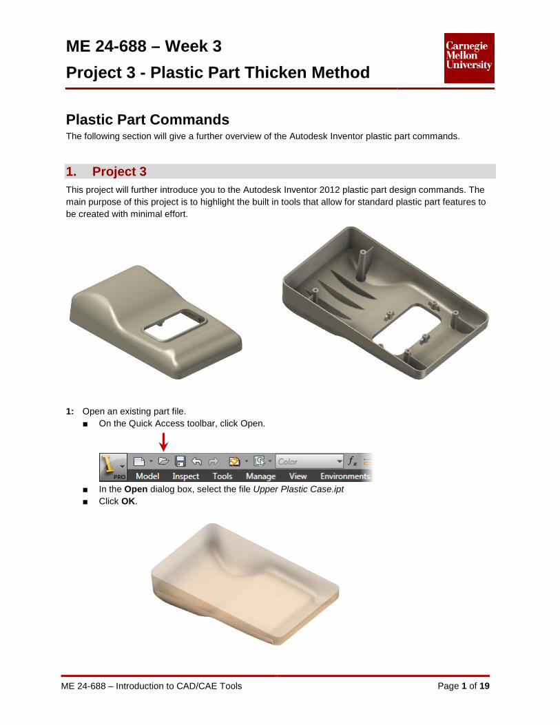
1. Project 3 This project will further introduce you to the Autodesk Inventor 2012 plastic part design commands. The main purpose of this project is to highlight the built in tools that allow for standard plastic part features to be created with minimal effort.
1: Open an existing part file.
■ On the Quick Access toolbar, click Open.
■ In the Open dialog box, select the file Upper Plastic Case.ipt ■ Click OK.
ME 24-688 – Week 3
Project 3 - Plastic Part Thicken Method
ME 24-688 – Introduction to CAD/CAE Tools Page 2 of 19
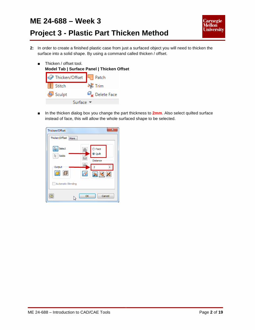
2: In order to create a finished plastic case from just a surfaced object you will need to thicken the surface into a solid shape. By using a command called thicken / offset.
■ Thicken / offset tool.
Model Tab | Surface Panel | Thicken Offset
■ In the thicken dialog box you change the part thickness to 2mm. Also select quilted surface instead of face, this will allow the whole surfaced shape to be selected.
ME 24-688 – Week 3
Project 3 - Plastic Part Thicken Method
ME 24-688 – Introduction to CAD/CAE Tools Page 3 of 19
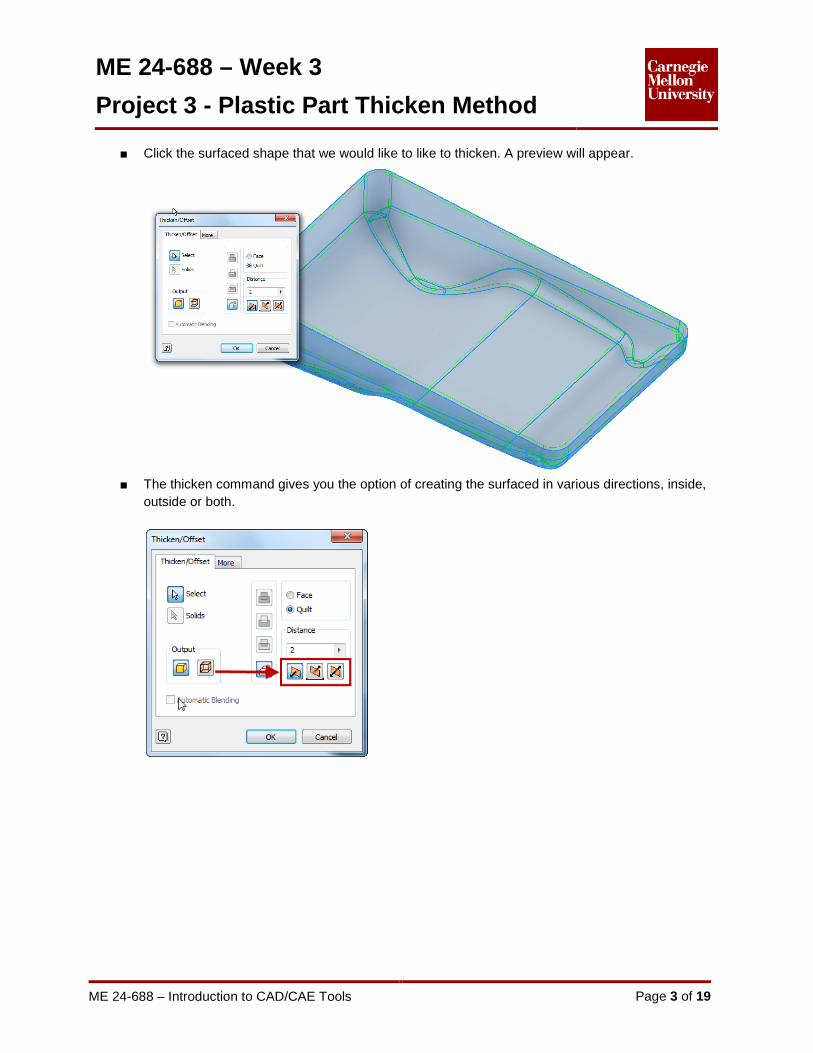
■ Click the surfaced shape that we would like to like to thicken. A preview will appear.
■ The thicken command gives you the option of creating the surfaced in various directions, inside,
outside or both.
ME 24-688 – Week 3
Project 3 - Plastic Part Thicken Method
ME 24-688 – Introduction to CAD/CAE Tools Page 4 of 19
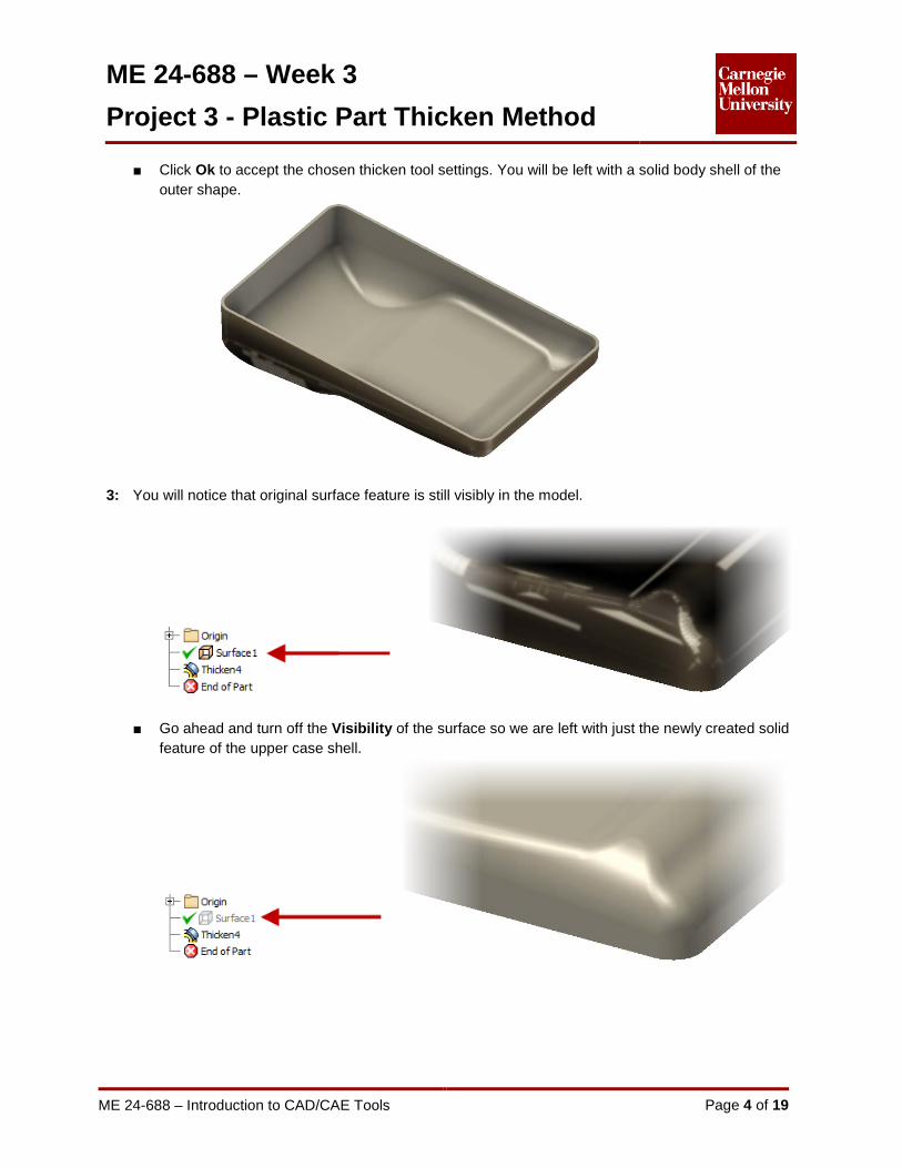
■ Click Ok to accept the chosen thicken tool settings. You will be left with a solid body shell of the outer shape.
3: You will notice that original surface feature is still visibly in the model.
■ Go ahead and turn off the Visibility of the surface so we are left with just the newly created solid feature of the upper case shell.

ME 24-688 – Week 3
Project 3 - Plastic Part Thicken Method
ME 24-688 – Introduction to CAD/CAE Tools Page 5 of 19
4: Using the Extrude command create a cut out lets go ahead and create a cut out for display screen that will be mounted to the upper shell case.

ME 24-688 – Week 3
Project 3 - Plastic Part Thicken Method
ME 24-688 – Introduction to CAD/CAE Tools Page 6 of 19
■ Using the standard Fillet and Extrude command, create raised bead around the opening for the display screen.
5: In order for plastic parts to be molded it is necessary for plastic parts to have surfaces that are slightly angles. These angles surfaces are commonly called Draft angles and allow for a plastic part to be removed from its mold. Let’s create a draft angle on the display opening. ■ Draft Tool
Model Tab | Modify Panel | Draft

ME 24-688 – Week 3
Project 3 - Plastic Part Thicken Method
ME 24-688 – Introduction to CAD/CAE Tools Page 7 of 19
■ Select the surface that is considered the pull surface. The direction in which the part will be pulled from the mold.
■ We can now select the faces that we would like to add the draft angle too. Click on the opening for the display screen. The program will automatically select all the faces that are connected to the opening.

ME 24-688 – Week 3
Project 3 - Plastic Part Thicken Method
ME 24-688 – Introduction to CAD/CAE Tools Page 8 of 19
■ The default draft angle is set at 2.5 degrees. Adjust this value as required.
■ Click Ok to accept the draft tool settings.
6: In order to connect the upper plastic case to the lower case we will need to add a few main mounting Bosses to the case shell. ■ Place a sketch on the plastic case to specify the location of the mounting bosses.
ME 24-688 – Week 3
Project 3 - Plastic Part Thicken Method
ME 24-688 – Introduction to CAD/CAE Tools Page 9 of 19
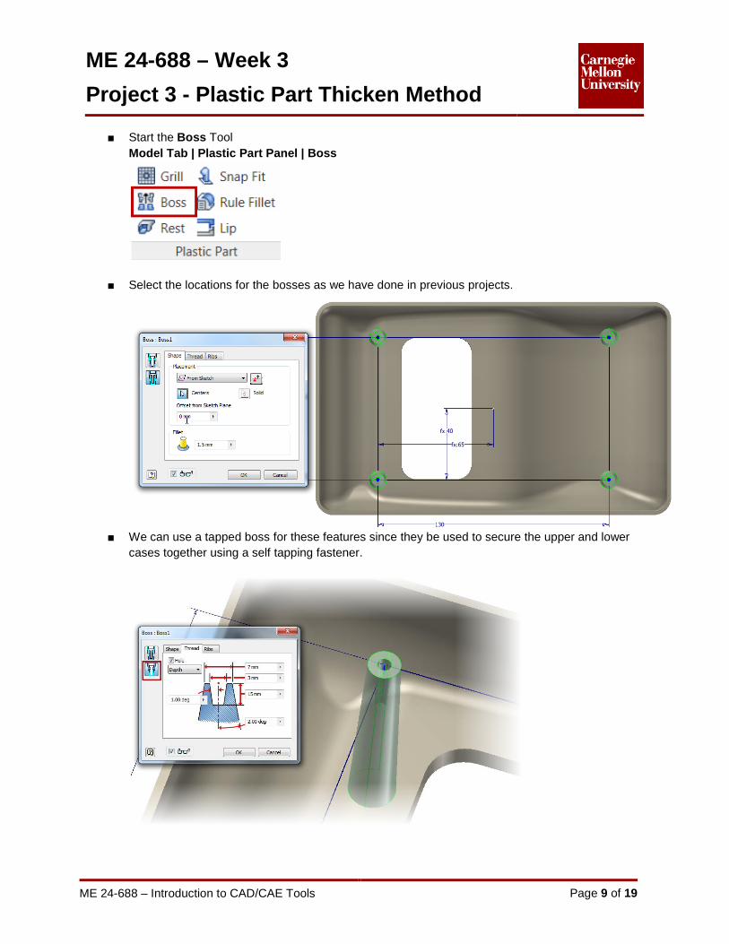
■ Start the Boss Tool Model Tab | Plastic Part Panel | Boss
■ Select the locations for the bosses as we have done in previous projects.
■ We can use a tapped boss for these features since they be used to secure the upper and lower
cases together using a self tapping fastener.

ME 24-688 – Week 3
Project 3 - Plastic Part Thicken Method
ME 24-688 – Introduction to CAD/CAE Tools Page 10 of 19
■ Click Ok to place the bosses to the upper case shell.
7: As described in the previous projects a standard feature on plastic parts is seam where two cases meet. Let’s use the lip tool again to create a lip feature around the upper case.
■ Lip tool
Model Tab | Plastic Part Panel | Lip
■ Place a lip around the outer case shell, as we have done in the previous project

ME 24-688 – Week 3
Project 3 - Plastic Part Thicken Method
ME 24-688 – Introduction to CAD/CAE Tools Page 11 of 19
■ Click Ok to create the lip on the case.
8: In order to mount the display screen into the upper case will need to create some sturdy small mounting bosses. ■ Create a work plane that is offset from the inner case surface the desired height of the bosses.
ME 24-688 – Week 3
Project 3 - Plastic Part Thicken Method
ME 24-688 – Introduction to CAD/CAE Tools Page 12 of 19
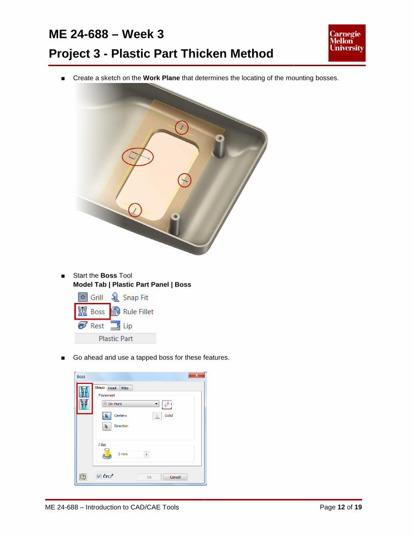
■ Create a sketch on the Work Plane that determines the locating of the mounting bosses.
■ Start the Boss Tool Model Tab | Plastic Part Panel | Boss
■ Go ahead and use a tapped boss for these features.
ME 24-688 – Week 3
Project 3 - Plastic Part Thicken Method
ME 24-688 – Introduction to CAD/CAE Tools Page 13 of 19
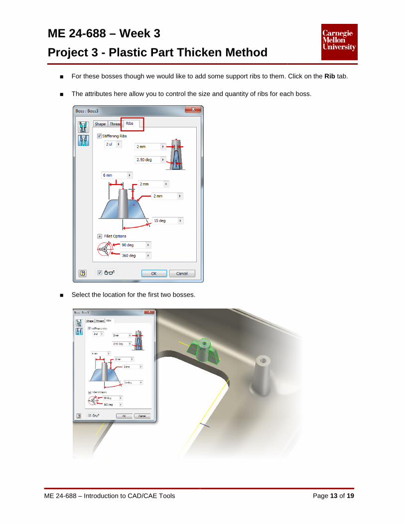
■ For these bosses though we would like to add some support ribs to them. Click on the Rib tab.
■ The attributes here allow you to control the size and quantity of ribs for each boss.
■ Select the location for the first two bosses.
ME 24-688 – Week 3
Project 3 - Plastic Part Thicken Method
ME 24-688 – Introduction to CAD/CAE Tools Page 14 of 19
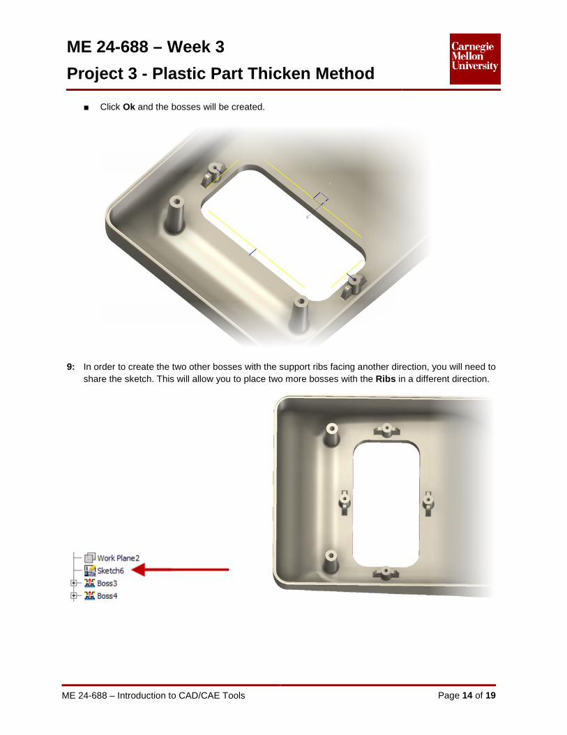
■ Click Ok and the bosses will be created.
9: In order to create the two other bosses with the support ribs facing another direction, you will need to share the sketch. This will allow you to place two more bosses with the Ribs in a different direction.
ME 24-688 – Week 3
Project 3 - Plastic Part Thicken Method
ME 24-688 – Introduction to CAD/CAE Tools Page 15 of 19
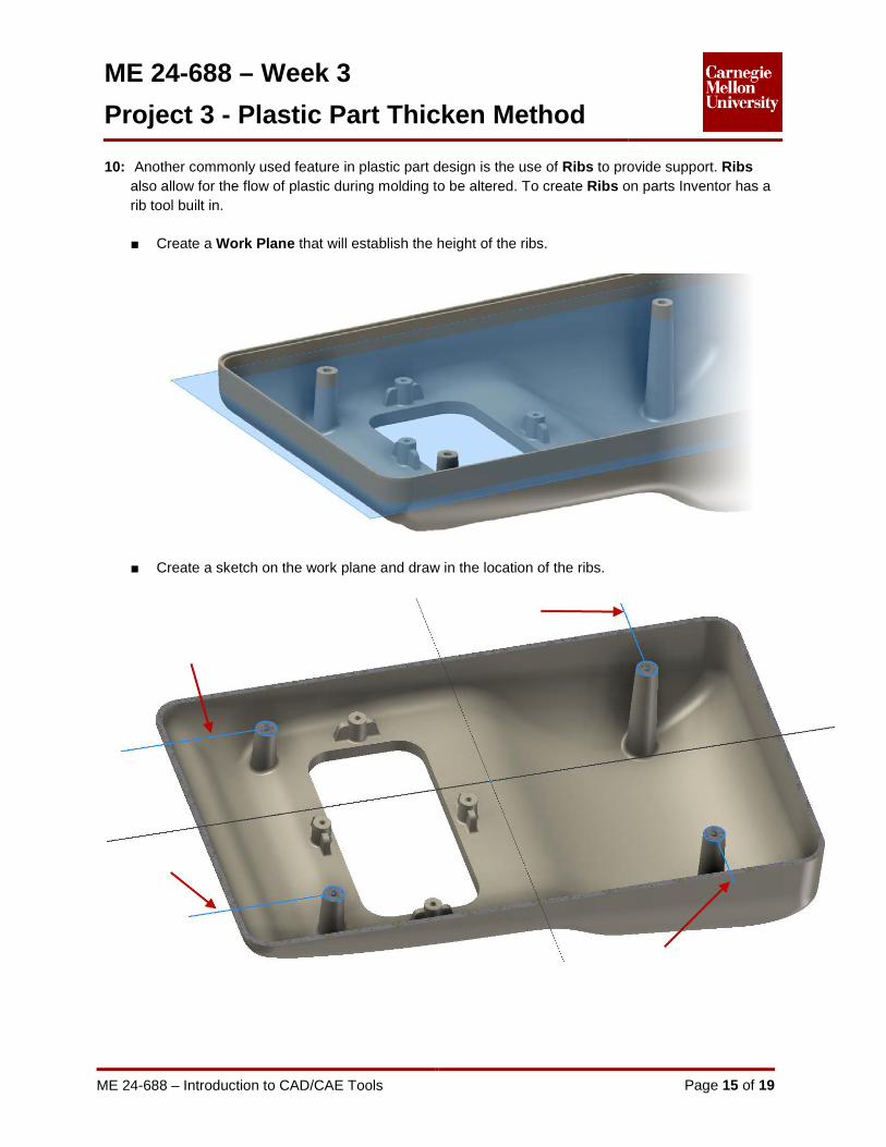
10: Another commonly used feature in plastic part design is the use of Ribs to provide support. Ribs also allow for the flow of plastic during molding to be altered. To create Ribs on parts Inventor has a rib tool built in. ■ Create a Work Plane that will establish the height of the ribs.
■ Create a sketch on the work plane and draw in the location of the ribs.

ME 24-688 – Week 3
Project 3 - Plastic Part Thicken Method
ME 24-688 – Introduction to CAD/CAE Tools Page 16 of 19
■ Rib tool Model Tab | Create Panel | Rib
■ Select the lines of the sketch you would like to turn into Ribs.
■ You can control to the direction the Rib will extruded in along with the position of the rib thickness.
ME 24-688 – Week 3
Project 3 - Plastic Part Thicken Method
ME 24-688 – Introduction to CAD/CAE Tools Page 17 of 19
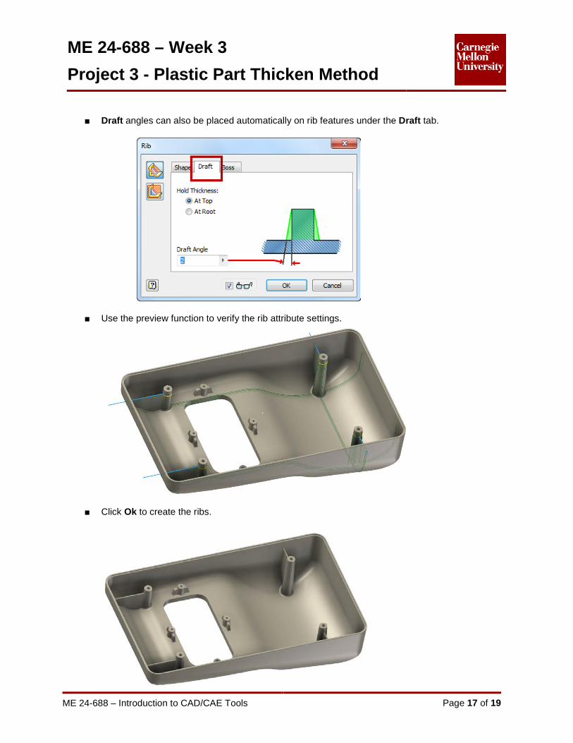
■ Draft angles can also be placed automatically on rib features under the Draft tab.
■ Use the preview function to verify the rib attribute settings.
■ Click Ok to create the ribs.
ME 24-688 – Week 3
Project 3 - Plastic Part Thicken Method
ME 24-688 – Introduction to CAD/CAE Tools Page 18 of 19
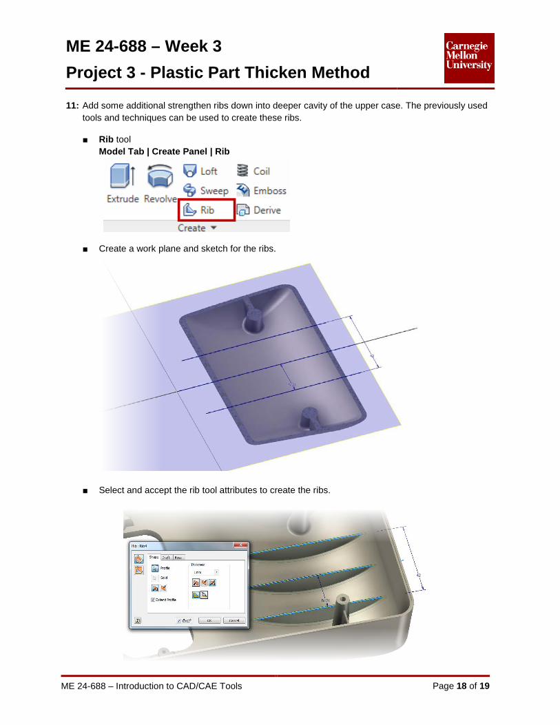
11: Add some additional strengthen ribs down into deeper cavity of the upper case. The previously used tools and techniques can be used to create these ribs. ■ Rib tool
Model Tab | Create Panel | Rib
■ Create a work plane and sketch for the ribs.
■ Select and accept the rib tool attributes to create the ribs.

ME 24-688 – Week 3
Project 3 - Plastic Part Thicken Method
ME 24-688 – Introduction to CAD/CAE Tools Page 19 of 19
12: We have complete creating a plastic case from a surfaced feature.