Embed Size (px)
Citation preview

1 of 1
CURRENT DATE OF REVISION MT 400 SECTION
MISCELLANEOUS MATERIALS AND TEST METHODS Test Date of Method Publication No. Title Pages or Revision MT 401 Sampling and Inspecting Corrugated Aluminum Pipe .................................. 2 pp May 2007
MT 402 Sampling and Testing Corrugated Steel Pipe ............................................... 2 pp Jun 2004
MT 403 Sampling and Inspection of Seeding and Landscaping Materials ................ 3 pp Jun 2004
MT 404 Inspecting Wood Products ............................................................................ 1 pp Jun 2004
MT 405 Wire Cloth Sieves for Testing Purposes ....................................................... 4 pp Jun 2004
MT 406 Sampling and Inspection of Signing Material and Signs ............................... 5 pp Jun 2004
MT 407 Method of Test for High Strength Bolts ......................................................... 4 pp Sep 2005
MT 408 Method of Sampling and Field Testing Brine Deicing Material ..................... 3 pp Feb 2010
MT 409 Welded Stud Shear Connectors.................................................................... Under Development
MT 410 Inspection, Sampling, Testing and Acceptance of Paint ............................... 3 pp Jun 2004
MT 411 Vacant
MT 412 Topsoil Sampling, Sample Preparation and Testing ..................................... 2 pp Sep 2018
MT 413 Inspection of Fencing Materials .................................................................... 2 pp Sep 2005
MT 414 Method of Acceptance for Reinforcing Steel ................................................. 5 pp Jun 2009
MT 415 Structural Steel .............................................................................................. Under Development
MT 416 Vacant
MT 417 Vacant
MT 418 Method of Acceptance for Miscellaneous Welded Items .............................. 1 pp Jun 2004
MT 419 Vacant
MT 420 Procedure to Check for Leaks Under Hydrostatic Pressure ......................... 3 pp Jun 2004
MT 421 Sampling Construction Fabrics ..................................................................... 2 pp Jun 2009
MT 422 Method of Test for Surface Smoothness and Profile .................................... 5 pp Apr 2012


MT 401-07 (05/15/07)
1 of 2
METHODS OF SAMPLING AND TESTING MT 401-07
METHOD OF SAMPLING AND INSPECTING CORRUGATED ALUMINUM PIPE (AASHTO M196, M197)
1 Scope: 1.1 This specification covers the testing and inspection guidelines for aluminum clad alloy culverts
and underdrains.
2 Referenced Documents: 2.1 AASHTO: M196 Corrugated Aluminum Pipe for Sewers and Drains M 197 Aluminum Alloy Sheet for Corrugated Aluminum Pipe ASTM: B 209 Specification for Aluminum and Aluminum-Alloy Sheet and Plate 3 Sampling: 3.1 Sampling shall be performed or witnessed by the testing agency at the point of fabrication. 3.2 Random sampling shall consist of at least one set of three 1” x 12” samples per gauge, alloy and
temper, lot number and type of corrugation. Samples shall be obtained a minimum of 3” from any edge.
3.3 Previously tested material that is properly marked and accepted need not be re-sampled but must be listed in the test report.
3.4 In the event that the samples fail to comply, two additional sets of three samples will be taken from the same gauge, alloy and temper, lot number and type of corrugation. Both sets must comply with the requirements or the entire lot number will be rejected.
3.5 Each corrugated sheet used in annular corrugated pipe, and each 2 ft. (0.6m) to 5 ft. (1.5m) of coiled sheet used in helically corrugated pipe, shall be identified by the fabricator showing the following:
3.5.1 Name of sheet manufacturer. 3.5.2 Identification of the pipe fabricator, if different than the sheet manufacturer. 3.5.3 Alloy and temper. 3.5.4 Specified thickness. 3.5.5 Fabricator’s date of corrugating or forming into pipe by a six (6) digit number indicating in order
the year, month and day of the month. 3.6 The marking shall be applied to the sheet by a permanent method such as coining into the metal.
This identification shall appear on the outside of the pipe.
3.7 Sheet Manufacturer’s Analysis: The manufacturer of each brand shall furnish a certificate setting forth the name or brand of aluminum alloy to be furnished, and a statement that the material conforms to the specified chemical composition limits. The certificate shall be sworn to for the manufacturer by a person having legal authority to bind the company.

MT 401-07 (05/15/07)
2 of 2
3 Fabrication: (continued) 3.8 Sheet Manufacturer’s Guarantee:
The manufacturer of the sheets shall submit, with the analysis, a guarantee providing that all aluminum alloy furnished shall conform to the applicable requirements of the latest revision of ASTM B209 for Alclad alloy 3004-H34 unless otherwise specified and shall bear a suitable identification brand or mark, and shall be replaced without cost to the purchaser when not in conformity with the specified analysis, sheet thickness, or cladding thickness, and the guarantee shall be so worded as to remain in effect so long as the manufacturer continues to furnish material.
3.9 Fabrication of the corrugated aluminum pipe shall conform to the requirements of AASHTO M
196, the Standard Specifications, and the plans for the specific project, and the Special Provisions.
4 Certification: 4.1 The testing agency shall submit appropriate manufacturer’s mill test reports and chemical
analysis representing each lot number used. The certification shall be submitted with the samples, and under separate cover. The reports shall include the following:
4.1.1 Lot number. 4.1.2 Gauge. 4.1.3 Corrugation size. 4.1.4 Diameter and quantity of pipe. 4.1.5 Type of seam. 4.1.6 Name of supplier. 4.1.7 Montana highway project for which the material is designated. 5 Approval for Shipments of Culverts 5.1 Culverts and/or related material shall not be approved for shipment until they have been found to
comply with our specifications. 5.2 Evidence of approval shall be by means of the inspecting agency’s ID stamp or tag placed on a
noticeable location on each section of the inspected material. 5.3 In the event of any questions pertaining to the approval for shipment of culverts and/or related
material, contact the Materials Bureau. 6 Field Inspection and Acceptance 6.1 The field inspection shall be made by the Project Manager who shall be furnished by the seller
with an itemized statement of the sizes and lengths of culvert pipe in each shipment. This inspection shall include an examination of the culvert pipe for deficiency in length of finished pipe, and any evidence of damage during shipment. Along with the proper approval stamp or tag from the inspecting agency.

MT 402-04 (06/01/04)
1 of 2
METHODS OF SAMPLING AND TESTING MT 402-04
METHOD OF SAMPLING AND TESTING CORRUGATED STEEL PIPE (AASHTO M 36)
1 Scope:
1.1 The specification covers corrugated steel pipe intended for use for storm water drainage, under-
drains, the construction of culverts, and similar uses. The steel sheet used in fabrication of the pipe has a protective metallic coating of zinc (galvanizing), aluminum, or aluminum-zinc alloy.
2 Referenced Documents: 2.1 AASHTO: M 36 Corrugated Steel Pipe, Metallic-Coated, for Sewers and Drains 3 Sampling Procedure: 3.1 Sampling shall be performed or witnessed by MDT or an approved inspecting agency at the point
of manufacture. 3.2 Random sampling shall consist of at least one set of three 3” x 3” samples per gauge, heat
number, lot number and type of corrugation. Samples shall be obtained a minimum of 3” from any edge.
3.3 Previously tested material that is properly marked and accepted need not be re-sampled, but must
be listed in the test report. 3.4 In the event that the samples fail to comply, two additional sets of three samples will be taken from
the same gauge, heat number, lot number and type of corrugation. Both additional sets must comply with the requirements or the entire lot number will be rejected.
4 Fabrication: 4.1 Fabrication of the corrugated steel pipe shall conform to the requirements of AASHTO M 36, the
Special Provisions, the Standard Specifications, and the plans for the specific project.
5 Certification: 5.1 The inspecting agency shall verify that all materials are in compliance with the “Buy America”
provision in the Montana Standard Specifications for Road and Bridge Construction. Upon receipt of the materials, the Contractor will submit the appropriate test reports and chemical analysis representing each lot number on the Contractors Certificate of Compliance, Form 406. The reports shall include the following:
5.1.1 Lot number 5.1.2 Heat number. 5.1.3 Gauge. 5.1.4 Corrugation size. 5.1.5 Diameter and quantity of pipe.

MT 402-04 (06/01/04)
2 of 2
5 Certification: (continued) 5.1.6 Type of seam. 5.1.7 Weight of coating in oz/ft² or g/m². 5.1.8 Name of supplier. 5.1.9 Montana Department of Transportation project for which the material is designated. 5.1.10 Two copies of the report are to be forwarded to the District Laboratory.
6 Approval for Shipment of Culverts: 6.1 Culverts and/or related material shall not be approved for shipment until they have been found to
comply with our specifications. 6.2 Evidence of approval shall be by means of the inspecting agencies ID stamp or tag placed on a
noticeable location on each section of the inspected material. 6.3 In the event of any questions pertaining to the approval for the shipment of culverts and/or related
material, contact the Materials Bureau. 7 Field Inspection and Acceptance: 7.1 Field inspection shall be made by the Engineering Project Manager who shall be furnished by the
seller with an itemized statement of the sizes and lengths of culvert pipe in each shipment. This inspection shall include an examination of the culvert pipe for deficiency in length and any evidence of damage during shipment along with the proper approval stamp or tag from the inspecting agency and be submitted on a Form 46.

MT 403-04 (06/01/04)
1 of 3
METHODS OF SAMPLING AND TESTING MT 403-04
SAMPLING AND INSPECTION OF SEEDING AND LANDSCAPING MATERIALS 1 Scope 1.1 Sampling, sample preparation and submittal, supervision of seed blending. 2 Referenced Documents
MT Materials Manual MT 412 Topsoil Sampling, Sample Preparation and Testing
3 Sampling Procedure 3.1 All proposed seed, other than Montana certified "blue tag" seed, will be sampled under MDT
supervision. Resampling will not be required if the proposed seed has been pretested at the grain and seed laboratory at Montana State University within a period of twelve (12) months. A miscellaneous sample sheet listing the supplier's name and all the information given on the purity and germination tag must be submitted to the Materials Bureau. List the name and approximate number of each kind or specie of restricted noxious weed seeds occurring per pound on the purity and germination tag. Acceptance of seed is based on compliance with the Standard Specifications for Road and Bridge Construction.
3.2 When sampling seeds in bags, a trier long enough to reach all areas in the bag will be used. The
trier must be designed so that it will remove an equal volume of seed from each part of the bag through which the trier travels. Unless the trier has partitions in the seed chamber, it must be inserted into the bags horizontally. Sample non-free-flowing seeds difficult to sample with a trier by thrusting the hand into the seed and removing representative portions. When a sample is taken with the hand, insert the hand flat and with the fingers together. Keep the fingers together as the hand is closed and withdrawn. Because of possible segregation, hand samples should be taken from various locations in the bags.
3.2.1 Seed in bags. 3.2.1.1 For lots of one to six bags, sample each bag. 3.2.1.2 For lots of more than six bags, sample five bags plus at least 10% of the number of bags in the
lot. Round numbers with decimals to the nearest whole number. Regardless of the lot size, it is not necessary to sample more than 30 bags.
3.2.1.3 Closed and open bags should be sampled with a long trier, probe, or bag sampler extending the
full length of the bag. In sampling open bags it must be recognized that the sample may not represent the original shipment.
3.2.1.4 A trier or probe is available from the Materials Bureau on request and must be returned
immediately upon completion of sampling. 3.2.1.5 Seed which has been pretested under Materials Bureau supervision need not be resampled by
project personnel. If there is a reason to believe that the material received on the project has not been pre-tested, the sampling procedure described above shall be adhered to.
3.3 Submit a one quart (one liter) container for each lot of seed sampled. Should the total quantity of
seed sampled be in excess of one quart (one liter), reduce the sample by means of quartering or splitting.

MT 403-04 (06/01/04)
2 of 3
3.4 Submit the seed sample along with the purity and germination tag directly to the Seed Lab at Montana State University. Submit a miscellaneous sample sheet with the following information to the Materials Bureau: all pertinent project information, supplier's name and address, kind of seed, all of the information given on the purity and germination tag and the amount of seed the sample represents.
3.5 Blending supervision – Seed blending performed in the field will be supervised on the job site by
project personnel. Arrangements will be made for the supervision of blending when performed by a dealer or supplier. A blending report will be submitted to the Materials Bureau.
3.6 On each seeding project, retain a one quart container of each blend until such time as the project
has been completed and accepted. The same will apply to seed not incorporated in a blend, but applied directly. This will constitute a referee sample should a question arise relative to the purity and germination of the original sample.
4 Fertilizer 4.1 Sampling will be performed by field personnel at the project site. In the case of blended fertilizer,
a sample of the blended material will be sampled for analysis. Obtain sufficient material to fill a one quart (one liter) container from the top, center, and bottom of each fertilizer container to be sampled. Only one sample will be required from each lot, except that sampling is not required for projects under 500 pounds.
4.2 Each sample submitted to the Materials Bureau will be accompanied by the certified chemical
analysis tag, a miscellaneous field sheet listing the supplier's name, the kind of fertilizer, the lot number, all of the information given on the certified chemical analysis tag, and the total pounds the sample represents.
5 Mulch 5.1 Vegetative mulch – The project inspection of mulch for conformance with the Standard
Specifications will be arranged by field personnel. In connection with this inspection, the Materials Bureau will be furnished with a report which will include the following information: Source, type, condition, purity, and moisture content of the mulch.
5.2 Wood cellulose fiber mulch – The project inspection of mulch for conformance with the Standard
Specifications will be arranged by field personnel. In connection with this inspection, the Materials Bureau will be furnished with a report, which will include the following information: Source, type, and moisture content of the mulch.
5.3 Peat moss – A one pound representative sample will be submitted to the Materials Bureau for pH
analysis. 5.4 Bark chip mulch – Bark chips derived from the bark of Douglas Fir, Pine, or Hemlock will be
acceptable. All material must be reasonably free from weed seeds and other foreign material such as grasses, chaff, and substances toxic to plant growth. Individual bark chips will have a maximum dimension of 3 inches and not more than 10% of the chips can pass through a 3/4 inch sieve. A 25-pound sample will be submitted to the Materials Bureau for testing.
5.5 Manure – The term "Manure" will apply to stockpiled, well-rotted cattle, sheep, or horse manure
or combinations of such, more than one year old, reasonably free of debris and foreign matter. Before being used in any planting operation, the manure must be shredded to break up large chunks and to assure proper mixing with other materials. Before any manure is hauled to the project site it must be approved by the landscape architect or engineer.
5.6 Fabricated netting – The project inspection of netting for conformance with the Standard
Specifications will be arranged by field personnel. In connection with this inspection, the Materials Bureau shall be furnished with a report which shall include the source, type, and condition of the material.

MT 403-04 (06/01/04)
3 of 3
6 Emulsified Binder 6.1 When the quantity of emulsified binder is in excess of 10,000 gallons, a one-quart representative
sample of the emulsified asphalt proposed for use on the project shall be submitted to the Materials Bureau. Ship emulsified binder in plastic containers.
7 Topsoil 7.1 With the exception of topsoil which has been stripped and is stockpiled for later replacement, a
two pound sample of each kind or type will be sampled and tested in accordance with MT-412. 8 Sod 8.1 The material will be inspected on-site, a miscellaneous field sample sheet (Form 46) will list
source, grass specie, and thickness of sod, and also the total quantity of material represented by the sample, and forwarded to the Materials Bureau.
9 Nursery Stock 9.1 The project inspection of nursery stock will be performed by the Manager, Field Project Unit for
conformance with the specifications contained in the project proposal. In connection with this inspection, the Materials Bureau is to be furnished with a report which will include the following information: supplier, stock name, quantity, condition, minimum and maximum size or spread of trees and shrubs, whether of nursery or collected stock, whether stock is bare-root, balled and burlapped or plotted and number of trees and shrubs accepted.
9.2 The following is an example of a nursery stock inspection report:
COMMON NAME BOTANICAL NAME QUANTITY SIZE
Ponderosa Pine Pinus ponderosa 6 1'6" - 1'0"
All of the specified size, all potted nursery stock, all in good condition and all accepted.
Common Lilac Syringa Vulgaris 140 25" - 35"
All of the specified size, all nursery stock, all in good condition and all accepted.


MT 404-04 (06/01/04)
1 of 1
METHODS OF SAMPLING AND TESTING
MT 404-04 METHOD FOR INSPECTING WOOD PRODUCTS (Montana Method) 1 Scope: 1.1 This method includes the inspection of all wood products at the mills, the treating plant and after
shipment to the job-site. 1.2 A detailed procedure for inspecting wood products is not included in this method because the
primary responsibility for such inspections is charged to the Inspector at the Materials Bureau. In the event division or other personnel are required to make inspections of wood products, attention is directed to paragraph 5.1, below.
2 Mill Inspection: 2.1 Plant inspection of all wood products will consist of checking grade, dimensions, etc., in accordance
with the applicable section in the Standard Specifications. 3 Treating Plant Inspection: 3.1 (Wood products to be treated may be inspected in the white to determine its suitability for
treatment.) After treating is completed, the wood products must be inspected again for: 3.1.1 Adequacy of the treatment. 3.1.2 Damage which may have been caused by or during the treating cycle, or in subsequent handling. 3.2 It is essential that the treating plants call the Materials Bureau at least 48 hours in advance of the
time requested for an inspection. 4 Final Inspection: 4.1 At the time of final inspection, all acceptable large timbers (guardrail posts, pilings, sign posts, etc.)
are individually stamped with the Circle (M) stamping hammer which denotes acceptance prior to shipment.
4.2 The acceptance of small items (fence posts, etc.) prior to shipment is indicated by inspection seals
attached to each bundle. 5 Job-Site Inspection: 5.1 In the event that the inspector from the Materials Bureau is unable to perform the inspection at the
plant, Division personnel may be called upon to perform the inspection in the field. Division personnel are directed to contact the Materials Bureau for specific instructions.
5.2 All wood products are subject to final field approval after delivery to the project.


MT 405-04 (06/01/04)
1 of 4
METHODS OF SAMPLING AND TESTING MT 405-04 WIRE CLOTH SIEVES FOR TESTING PURPOSES (Modified AASHTO M 92) 1 Scope: 1.1 This specification covers the requirements for the design and construction of sieves using a
medium of woven-wire cloth mounted in a frame for use in testing for the classification of materials according to designated nominal particle size and wire cloth, meeting the specifications of Table 1, to be designated test grade wire cloth. All subsequent references to wire cloth shall mean test grade wire cloth.
2 Referenced Documents: 2.1 AASHTO: M 92 Wire Cloth and Sieves for Testing Purposes 3 Sieve Cloth Requirements: 3.1 Wire cloth used in U.S.A. standard testing sieves meeting the specifications shown in Table 1
shall be designated “test grade”. Test grade cloth shall be woven from stainless steel, brass, bronze, or other suitable wire with a plain weave, except that cloth with openings of 63 µm (No. 230) and finer may be woven with a twill weave. The wire shall not be coated or plated.
3.2 The openings of the sieve cloth of successive sieves from a base of 1 mm in the ration of
approximately 4√2 :1. 3.3 All measurements of openings and wire diameters shall be made along the midpoints of the
opening. 3.4 Sieve cloth shall conform to the dimensional requirements of Table 1. The average opening
(distance between parallel wires measured at the center of the opening), in the horizontal and vertical directions measured separately, shall conform to the values in Column 1, within the permissible variation in average opening size shown in column 4. Not more than 5% of the openings shall exceed the value shown in Column 5. The maximum individual opening size shall not exceed the value shown in Column 6.
3.4.1 The average diameter of the horizontal and vertical wires, measured separately, shall conform to
the diameter in Column 7 within the tolerances in Footnote A of Table 1. 3.5 Wires shall be crimped in such a manner that they will be rigid when in use. 3.6 There shall be no punctures or obvious defects in the wire cloth. 4 Test Sieve Frames: 4.1 General Requirements - Frames for wire cloth sieves shall be constructed in such a manner as to
be rigid. The wire cloth shall be mounted on the frame without distortion, looseness or waviness. To prevent the material being sieved from catching in the joint between the wire cloth and the frame, the joint shall be filled smoothly or constructed so the material will not be trapped.
4.2 Standard Frames--The standard sieve frame shall be circular with nominal diameters of 3, 6, 8,
10 or 12 inches (76, 512, 203, 254, or 305 mm) as may be specified. The dimensions shall conform to the requirements of Table 2. Frames shall be made from noncorrosive material such as brass or stainless steel and be of seamless construction.

MT 405-04 (06/01/04)
2 of 4
4 Test Sieve Frames: (continued) 4.2.1 The bottom of the frame shall be constructed so as to provide an easy sliding fit with any sieve
frame of the same nominal diameter conforming to the specified dimensions. 4.2.2 The joint or fillet at the connection of the sieve cloth to the frame will provide a minimum clear
sieving surface with a diameter equal to the nominal diameter less 0.5 in. (13 mm). 4.3 Nonstandard Frames – Other sieve frames may be square, rectangular, or circular. The frame
may have the sieve cloth permanently installed, or be designed to permit replacement. The provisions of 5.1 apply.
Note 1 – While there are no requirements for nesting of nonstandard frames, care should be applied in
the use to prevent loss of material during analysis. 4.4 Pans and Covers – Pans and covers for use with sieves shall be made so as to nest with the
sieves. Pans with extended rims (“stacking skirts”) shall be furnished when specified. The pans and covers shall conform to the dimensions of Table 2.
5 Product Marking: 4.1 Each sieve shall bear a label marked with the following information: 4.1.1 U.S.A. Standard Testing Sieve, 4.1.2 ASTM designation E 11, 4.1.3 Standard sieve designation (from Table 1, Column 1), 4.1.4 Name of manufacturer or distributor, and 4.1.5 Alternative sieve designation (from Table 1, Column 2) Optional. 4.1.6 Each test sieve shall bear a unique serial number permanently engraved or etched onto the sieve
frame, skirt or nameplate.

MT 405-04 (06/01/04)
3 of 4
TABLE 1 Nominal Dimensions, Permissible Variations for Wire Cloth of Standard Test Sieves (U.S.A. Standard Series) Permissible Variation Maximum of Average Opening Nominal Opening from Size for Sieve the Standard Not More Maximum Nominal Sieve Designation Opening, Sieve than 5% of Individual Wire Standardb Alternative in.c Designation Openings Opening Diameter, mm mm mm mm mma (1) (2) (3) (4) (5) (6) (7) 125 5 in. 5 ±3.7 130.0 130.9 8.0 106 4.24 in. 4.24 ±3.2 110.2 111.1 6.40 100d 4 in.d 4 ±3.0 104.0 104.8 6.30 90 3½ in. 3.5 ±2.7 93.6 94.4 6.08 75 3 in. 3 ±2.2 78.1 78.7 5.80 63 2½ in. 2.5 ±1.9 65.6 66.2 5.50 53 2.12 in. 2.12 ±1.6 55.2 55.7 5.15 50d 2 in.d 2 ±1.5 52.1 52.6 5.05 45 1¾ in. 1.75 ±1.4 46.9 47.4 4.85 37.5 1½ in. 1.5 ±1.1 39.1 39.5 4.59 31.5 1¼ in. 1.25 ±1.0 32.9 33.2 4.23 26.5 1.06 in. 1.06 ±0.8 27.7 28.0 3.90 25.0d 1 in.d 1 ±0.8 26.1 26.4 3.80 22.4 7/8 in. 0.875 ±0.7 23.4 23.7 3.50 19.0 3/4 in. 0.750 ±0.6 19.9 20.1 3.30 16.0 5/8 in. 0.625 ±0.5 16.7 17.0 3.00 13.2 0.530 in. 0.530 ±0.41 13.83 14.05 2.75 12.5 1/2 in.d 0.500 ±0.39 13.10 13.31 2.67 11.2 7/16 in. 0.438 ±0.35 11.75 11.94 2.45 9.5 3/8 in. 0.375 ±0.30 9.97 10.16 2.27 8.0 5/16 in. 0.312 ±0.25 8.41 8.58 2.07 6.7 0.265 in. 0.265 ±0.21 7.05 7.20 1.87 6.3d 1/4 in.a 0.250 ±0.20 6.64 6.78 1.82 5.6 No. 3½ 0.223 ±0.18 5.90 6.04 1.68 4.75 No. 4 0.187 ±0.15 5.02 5.14 1.54 4.00 No. 5 0.157 ±0.13 4.23 4.35 1.37 3.35 No. 6 0.132 ±0.11 3.55 3.66 1.23 2.80 No. 7 0.111 ±0.095 2.975 3.070 1.10 2.36 No. 8 0.0937 ±0.080 2.515 2.600 1.00 2.00 No. 10 0.0787 ±0.070 2.135 2.215 0.900 1.70 No. 12c 0.0661 ±0.060 1.820 1.890 0.810 1.40 No. 14 0.0555 ±0.050 1.505 1.565 0.725 1.18 No. 16 0.0469 ±0.045 1.270 1.330 0.650 1.00 No. 18 0.0394 ±0.040 1.080 1.135 0.580 0.850 No. 20 0.0331 ±0.035 0.925 0.970 0.510 0.710 No. 25 0.0278 ±0.030 0.775 0.815 0.450 0.600 No. 30 0.0234 ±0.025 0.660 0.695 0.390 0.500 No. 35 0.0197 ±0.020 0.550 0.585 0.340 0.425 No. 40 0.0165 ±0.019 0.471 0.502 0.290 0.355 No. 45 0.0139 ±0.016 0.396 0.425 0.247 0.300 No. 50 0.0117 ±0.014 0.337 0.363 0.215 0.250 No. 60 0.0098 ±0.012 0.283 0.306 0.180 0.212 No. 70 0.0083 ±0.010 0.242 0.263 0.152 0.180 No. 80 0.0070 ±0.009 0.207 0.227 0.131 0.150 No. 100 0.0059 ±0.008 0.174 0.192 0.110

MT 405-04 (06/01/04)
4 of 4
TABLE 1 Nominal Dimensions, Permissible Variations for Wire Cloth of Standard Test Sieves (U.S.A. Standard Series) Permissible Variation Maximum of Average Opening Nominal Opening from Size for Sieve the Standard Not More Maximum Nominal Sieve Designation Opening, Sieve than 5% of Individual Wire Standardb Alternative in.c Designation Openings Opening Diameter, mm mm mm mm mma (1) (2) (3) (4) (5) (6) (7) 0.125 No. 120 0.0049 ±0.007 0.147 0.163 0.091 0.106 No. 140 0.0041 ±0.006 0.126 0.141 0.076 0.0090 No. 170 0.0035 ±0.005 0.108 0.122 0.064 0.075 No. 200 0.0029 ±0.005 0.091 0.103 0.053 0.063 No. 230 0.0025 ±0.004 0.077 0.089 0.044 0.053 No. 270 0.0021 ±0.004 0.066 0.076 0.037 0.045 No. 325 0.0017 ±0.003 0.057 0.066 0.030 0.038 No. 400 0.0015 ±0.003 0.048 0.057 0.025 0.032d No. 450d 0.0012 ±0.003 0.042 0.050 0.028 0.025d No. 500d 0.0010 ±0.003 0.034 0.041 0.025 0.020d No. 635d 0.0008 ±0.003 0.029 0.035 0.020
TABLE 2 Dimensions of Standard Frames Nominal Typical FrameA
Diameter Mean Diameter, in. (mm) In. Inside at TopB Outside of Skirt Nominal HeightC in. (mm) 3 3.000 + 0.030/-0.000 3.000 + 0.000/-0.030 1 1/4 (32) FHD
(76 + 0.76/ -0.00) (76 + 0.00/ -0.76) 5/8 (16) HH 6 6.000 + 0.030/-0.000 6.000 + 0.000/-0.030 1 3/4 (45) FH (152 + 0.76/ -0.00) (152 + 0.00/ -0.76) 1 (25) HH 8 8.000 + 0.030/-0.000 8.000 + 0.000/-0.030 2 (50) FH (203 + 0.76/ -0.00) (203 + 0.76/ -0.76) 1 (25) HH 10 10.000 + 0.030/-0.000 10.000 + 0.000/-0.030 3 (76) FH (254 + 0.76/ -0.00) (254 + 0.00/ -0.76) 1 1/2 (38) HH 12 12.000 + 0.030/-0.000 12.000 + 0.000/-0.030 3 1/4 (83) FH (305 + 0.76/ -0.00) (305 + 0.00/ -0.76) 2 (50) IH 1 5/8 (41) HH A Other frame heights are not precluded. B Measured 0.2 in. (5 mm) below the top of the frame. C Distance from the top of the frame to the sieve cloth surface. D FH = full height, HH = half height, IH = intermediate height.

MT 406-04 (06/01/04)
1 of 5
METHODS OF SAMPLING AND TESTING MT 406-04
METHOD OF SAMPLING AND INSPECTION OF SIGNING MATERIAL AND SIGNS (Montana Method)
1 Scope 1.1 Following the determination of a successful bidder, and upon the letting of a project to contract, a
letter is sent to the prime contractor by the Materials Bureau requesting the source of bid items in the contract. These items include signing material and signs. Upon receipt of the information, the Certification Inspection Supervisor in the Materials Bureau will arrange for inspection. The following procedures and requirements shall be observed whenever signs are included in a project.
2 Referenced Documents 2.1 Montana Department of Transportation Detailed Drawings 3 Reporting 3.1 A copy of all correspondence, test results, certificates and other pertinent documents shall be
submitted to the Materials Bureau, attention Certification Inspection Supervisor. 4 Signing Material 4.1 Inspection of signing material will be performed by either another state, by a commercial
inspection and testing agency, or if the material was not pre-inspected by field personnel. 5 Sign Fabrication Inspection 5.1 Sign fabrication inspection involves visual observation of sign materials, fabrication procedures,
and the manufactured product to ensure that it will serve the intended purpose for its expected performance life.
5.2 Material specifications are outlined in the Standard Specifications for Road and Bridge
Construction and in the contract special provisions. Materials used in the fabrication of highways signs are inspected by an inspection agency for each construction contract.
5.3 In-Plant sign inspection and approval does not constitute mandatory acceptance by the Project
Manager of the delivered product. It is possible that signs may be damaged in transit because of inadequate packaging or poor handling and will be rejected at the project site. Approval of a sign at the point of fabrication means that the inspector has assured himself that all materials used meet the plan specifications and that finished signs are satisfactory in appearance and workmanship.
6 Materials 6.1 Inspection & Sampling: Following is a listing of the materials used in the fabrication of signs and
the required sampling procedures before the subject material may be approved for use. 6.2 6061 T6 or 5052 H38 Aluminum Sheeting can be accepted on certification of conformance and
certified mill test reports. No sample is required unless deemed necessary by the Inspector. If samples are required, they shall be sampled as follows: Two samples of size 3/4 inch x 9 inch of each gauge will be taken from each consignment of aluminum received for signing. Samples will be oriented with the longer dimension parallel to the direction of rolling. The Materials Bureau will machine these samples to comply with ASTM E8-80A. A Certificate of Compliance including Certified Mill Test Reports of each gauge is required.
6.3 Aluminum Sign Blanks: Each consignment of aluminum sign blanks is spot checked with a
micrometer for gauge thickness conformance. Certificates of Compliance and a Certified Mill Test Report of each gauge are required.

MT 406-04 (06/01/04)
2 of 5
6.4 6063 T6 Extruded Aluminum T-Sections (Wind Beam): Certificates of Compliance, Certified Mill
Test Reports, and Chemical Analysis are required for each order. No sample is required unless deemed necessary by the Inspector.
6.5 HD (High Density) Plywood: The minimum allowable plywood grade shall be B-B high density
overlay 60/60 with amber overlay on both sides, and a minimum thickness of 3/4" or as shown on plans. A spot check on thickness requirements, grade-trademark for Grade and Type of plywood, and a letter attesting to the standard of the plywood received is required. No sample is required unless deemed necessary by the Inspector.
6.6 Reflective Sheeting: A portion of each roll will be visually inspected for imperfections. A
Certificate of Compliance including the type, grade, color, and purchase order number is required for each roll used in the signing fabrication.
Note 1 –Reflective sheeting from each manufacturer will be sent to the Materials Bureau for reflectivity
testing on an annual basis. 6.7 Sign Faces: No sampling is required for reflective or non-reflective sign faces. A visual inspection
for conformance and imperfections will be performed on each order of sign faces received. A Certificate of Compliance is required for each shipment. The certificate will include type of material and purchase order number.
6.8 Applied or Demountable Copy A Certificate of Compliance is required for each order prior to
usage. The reflective sheeting for all sign copies shall be Silver-White No. 2 (Parkway - if a 3M product). Encapsulated lens, wide angle reflective sheeting may be used when specified in the plans.
7 Fabrication: Items to be observed by the Inspector During Sign Fabrication 7.1 Approved materials. 7.2 Visual check of material color and color match with a 150 watt flood light held at eye level at a
distance of 50 feet from material being observed. 7.3 Visual check of uniform legend color tone and uniform reflectivity with a 150 watt flood light held
at eye level at a distance of 50 feet from legend being observed. 7.4 Visual check of splices. 7.5 Fabrication 7.5.1 Correct thickness of aluminum or plywood. 7.5.2 Correct material for reflectorized and non-reflectorized signs, (sheeting and copy). 7.5.3 Correct "T" sections (wind beam) and proper spacing of "T" sections, (Standard Drawing No. 619-
04 and 619-06). 7.5.4 Correct spacing of rivets with heads painted to match signs, (Standard Drawing No. 619-04).
MT 406-04 (06/01/04)
3 of 5
7.5.5 Correct spacing of aluminum clips on "T" sections on plywood, (Standard Drawing No. 619-06). 7.5.6 Correct sign size, color, and whether copy and background sheeting are reflectorized or non-
reflectorized. 7.5.7 Corners of control signs rounded. 7.5.8 Corners of guide signs rounded when so noted on plans. 7.6 Non-Standard Items: 7.6.1 Conformance to contract special provisions. Conformance to special mounting details shown on
the plans. 8 Application of Materials 8.1 Use of approved equipment and qualified personnel. 8.2 Sheeting properly applied. 8.3 Absence of foreign particles under applied sheeting. 8.4 Absence of air bubbles under applied sheeting. 8.5 Absence of loose edges. 9 Workmanship 9.1 Correct sign layout and size. 9.2 Sharp clear screened sign messages. 9.3 Proper horizontal and vertical spacing. 9.4 Correctly spelled words. 9.5 Symbols correctly depicted. 9.6 Back of sign clean and free of corrosion. 9.7 Sign number on back of guide signs. 10 Design Conformance 10.1 Completed Signs: 10.1.1 All completed signs will conform to the Manual on Uniform Traffic Control Devices, and Standard
Highway Signs as specified in the MUTCD, 1978 with addendums; except as may be provided for in the Montana Standard Drawings, Montana Sign Index, or contract plans and approved shop drawings.
10.1.2 All completed signs that are in conformance will be stamped on the back of the sign, by the
inspector, with the inspecting agency's stamp of approval.

MT 406-04 (06/01/04)
4 of 5
10.1.3 Test reports for signing material, inspected and sampled by a commercial agency, will be sent to the inspecting agency by the Materials Bureau upon completion of the tests.
10.1.4 Test reports for material sampled by field personnel will be issued upon completion of the tests. 10.1.5 The supplier for all major signing material must provide the manufacturer’s Certificates of
Compliance. Copies of all certificates will be kept in the Materials Bureau project files. 10.1.6 Acceptance reports for material used on pre-inspected signs that were supplied from out-of-state
will be submitted to the field in the final report. 10.1.7 The field shall provide the Materials Bureau with inspection and acceptance reports whenever un-
inspected signing material that has been supplied from out-of-state is delivered to the project. (Section 10.2.4).
10.2 Signs Supplied Locally or from Out-of-State: 10.2.1 Signs that have been supplied locally or out-of-state are inspected at the source as designated by
the Materials Bureau. Following inspection, a report listing the number and kind of signs will be submitted to the field and to the Materials Bureau.
10.2.2 In the event that the signs have not been pre-inspected, the Materials Bureau shall require a Field
Inspection and Acceptance Report in addition to the manufacturer's Certificates of Compliance (Section 10.1.5).
10.2.3 Signs are inspected for conformance with the Montana Department of Transportation
specification requirements. Locally inspected signs will bear evidence of having been inspected by the presence of the inspecting agency's stamp of approval. Unpackaged signs will bear a stamp on the back of the sign, while packaged signs will bear a stamp on the package face.
10.2.4 Locally supplied signs that have not been inspected may be delivered to a project only in the case
of extreme urgency for installation. For such cases, the suppliers have been directed to immediately forward a letter to the Materials Bureau and to the Project Manager describing the circumstances under which the signs (not inspected) were shipped. This letter must designate the project and location to which the signs were delivered and list the kind and quantity of signs. Signs that have been shipped without inspection shall not be accepted until the manufacturer has submitted this letter.
10.2.5 It is imperative that the Materials Bureau, attention Certification Inspection Supervisor, be
informed of the field inspection and acceptance of all signs that do not show evidence of inspection at the source. The following information will be included in this inspection report:
10.2.5.1Appearance and workmanship 10.2.5.2Conformance to specifications 10.2.5.3Type, size, and quantity 10.2.5.4Gauge of aluminum 10.2.5.5Thickness or ply of plywood

MT 406-04 (06/01/04)
5 of 5
10.3 Final Signing Material and Sign Acceptance Reports: 10.3.1 Signing material and signs which have been inspected by a commercial agency will be accepted
upon receipt of all required Certificates of Compliance. 10.3.2 Signing material and signs which have been supplied from out-of-state but which have not been
inspected will be accepted upon receipt of required certificates from the supplier, a field inspection, and an acceptance report.
10.3.3 Signing material and signs which have been supplied from out-of-state and have been inspected
by a commercial agency will be accepted on the reports issued by the agency. 10.3.4 Signing material and signs which have been supplied locally and have been inspected by the
District will be accepted on the reports issued by the District. 10.3.5 All signing material and signs, regardless of source and inspection procedure, are subject to final
field approval.


MT 407-05 (09/01/05)
1 of 4
METHODS OF SAMPLING AND TESTING MT 407-05
METHOD OF TEST FOR HIGH-STRENGTH BOLTS
1 Scope: 1.1 The method covers rotational capacity testing of high strength bolts used in bridge construction.
2 Referenced Documents: 2.1 AASHTO: M 164 (M 164M), High-Strength Bolts for Structural Joints M 291 (M 291M), Carbon and Alloy Steel Nuts M 292 (M 292M), Carbon and Alloy Steel Nuts for Bolts for High-Pressure or High-Temperature
Service or Both Procedure A: (Long Bolts in Tension Calibrator) 3 Apparatus: 3.1 A Skidmore-Wilhelm calibrator for measuring bolt tension, of sufficient capacity for the bolts to be
tested. 3.2 Calibrated torque wrench. 3.3 Spacers and/or washers with a maximum hole size 1/16 in. (2mm) larger than the bolt to be tested. 3.4 A steel section on which to mount the bolt calibrator. The flange of a girder or a cross-frame
accessible from the ground is acceptable. 4 Procedure:
4.1 Use black fasteners oily to the touch at testing. Clean all weathered or rusty fasteners of all rust
and re-lubricate prior to testing. Lubricate all galvanized fasteners with a visible dye, so a visual check verifies the lubricant’s presence.
4.2 Measure the bolt length, not including the head. 4.3 Thread a nut onto the bolt with sufficient spacers or washers to bring the bolt end to at least flush
with the tightened nut to a maximum bolt stick-out of three threads. Provide 3 to 5 threads between the inside faces of the nut and the bolt head. Always use a hardened washer under the nut.
4.4 Tighten the nut with a wrench to produce the appropriate snug tension from Table 1, with an
allowable error range from 0 kips to +2 kips (0 to + 9 kn). The snug condition should be the normal effort applied with a 12-inch wrench.
Table 1
Bolt Dia. (in.) ½ 5/8 ¾ 7/8 1 1 1/8 1 ¼ 1 3/8 1 1/2 Snug Tension (kips) 1 2 3 4 5 6 7 9 10
Bolt Dia. (mm) 20 22 24
Snug Tension (kN) 13 18 23

MT 407-05 (09/01/05)
2 of 4
4 Procedure: (continued) 4.5 Match-mark the bolt, nut and face plate of the calibrator. 4.6 Using the torque wrench, tighten the nut to at least the tension in Table 2. Record the bolt tension
and the torque that produced the tension. (Measure the torque with the nut in motion). Calculate the following value for maximum allowable torque given by: T = 0.25 PD, where P=
tension in lbs. (N) and D = diameter of bolt in feet (m). The fastener assembly fails the test at this point if the recorded torque exceeds the value, T, as
calculated above.
Table 2 Bolt Dia. (in.) ½ 5/8 ¾ 7/8 1 1 1/8 1 ¼ 1 3/8 1 1/2 Tension (kips) 12 19 28 39 51 56 71 85 103
Bolt Dia. (mm) 20 22 24 Tension (kN) 125 173 227
4.7 Tighten the nut further by the number of turns shown in Table 3, using the radial lines on the
calibrator faceplate for reference. The rotation is measured from the initial marking in step 4.5. Record the bolt tension. Bolt and nut assemblies which strip or fracture before achieving the full rotation have failed the test.
Table 3
Bolt Length
4 x bolt dia. or less
Greater than 4 but no more than 8 x dia.
Greater than 8 x dia.
Required Rotation 2/3 1 1 1/6 4.8 Compare the bolt tension recorded from Section 4.7 with the appropriate value from Table 4.
Fastener assemblies that do not provide the minimum required tension shown in Table 4 at the rotation shown in Table 3 have failed the test.
Table 4
Bolt Dia. (in.) ½ 5/8 ¾ 7/8 1 1 1/8 1 ¼ 1 3/8 1 1/2 Tension (kips) 14 22 32 45 59 64 82 98 118
Bolt Dia. (mm) 20 22 24 Tension (kN) 142 200 262
4.9 Remove the nut and bolt from the calibrator and examine them. The fastener assembly has failed
the test if threads show signs of stripping, shear or torsion failure or the nut fails to turn freely, by hand, on those threads occupied by the nut in the test position. (The nut does not have to freely turn the entire length of the thread to pass this test.)
Procedure B (Bolts too short for tension calibrator) 5 Apparatus: 5.1 Calibrated torque wrench and hand wrenches. 5.2 Spacers and/or washers with a maximum hole size 1/16 in. (2mm) larger than the bolt. 5.3 A steel section with holes sized 1/16 in. (2mm) larger then the bolt diameter, with a plate thickness
that will accommodate section 6.3.

MT 407-05 (09/01/05)
3 of 4
6 Procedure:
6.1 Use black fasteners oily to the touch at testing. Clean all weathered or rusty fasteners of all rust and re-lubricate prior to testing. Lubricate all galvanized fasteners with a visible dye, so a visual check verifies the lubricant’s presence.
6.2 Measure the bolt length, not including the head. 6.3 Install the fastener assembly in the steel plate with sufficient spacers or washers to bring the bolt
end out at least flush with the tightened nut, to a maximum bolt stick-out of three threads. Provide three to five threads in the length of bolt between the inside faces of the nut and bolt head. Always use a hardened washer under the nut.
6.4 Snug the bolt by applying no more than 20% of the torque allowed in Table 6 below, using a
torque wrench. Measure and record the torque (with the nut in motion) on the bolt. 6.5 Match-mark the nut, bolt and plate. 6.6 Tighten the nut with the torque wrench by the number of turns from Table 5. Use a hand wrench
to ensure that the bolt does not turn. Measure and record the torque with the nut in motion.
Table 5
Bolt Length
4 x bolt dia. or less Greater than 4 but no more
than 8 x bolt dia. Required Rotation 1/3 turn 1/2 turn
If the measured torque from section 6.6 exceeds the appropriate value from Table 6, the fastener assembly has failed the test. Assemblies that fail prior to completing this rotation, by stripping or fracture, fail the test.
Table 6
Bolt Dia. (in.) ½ 5/8 ¾ 7/8 1 1 1/8 1 ¼ 1 3/8 1 1/2 Torque (Ft/lbs) 150 290 500 820 1230 1500 2140 2810 3690
Bolt Dia. (mm) 20 22 24 Tension (N-m) 710 1100 1570
6.7 Tighten the nut further by the appropriate number of turns from Table 7, using the reference mark
from section 6.5. Assemblies that fail prior to completing this rotation, by stripping or fracture, fail the test.
Table 7
Bolt Length
4 x bolt dia. or less Greater than 4 but no more
than 8 x bolt dia. Required Rotation 2/3 turn 1 turn
6.8 Remove the nut and the bolt from the plate and examine them. The fastener assembly has failed
the test if threads show signs of stripping, shear or torsion failure or the nut fails to turn freely by hand, on those threads occupied by the nut in the test position. (The nut does not have to freely turn the entire length of the thread to pass this test.)
7 Report: 7.1 Date tested, 7.2 Name of tester,

MT 407-05 (09/01/05)
4 of 4
7 Report: (continued) 7.3 Procedure performed (A or B), 7.4 Bolt length, 7.5 Bolt tension, 7.6 Bolt torque at tension.

MT 408-10 (2/25/10)
1 of 3
METHODS OF SAMPLING AND TESTING
MT 408-10
METHOD OF SAMPLING AND FIELD TESTING BRINE DEICING MATERIAL 1 Scope 1.1 This method covers the sampling and testing of brine deicing material in the field. 2 Reference Documents
ASTM D891 Standard Test Methods for Specific Gravity, Apparent, of Liquid Industrial Chemicals E126 Standard Test Method for Inspection, Calibration, and Verification of ASTM Hydrometer Other Standards Clear Roads Document - Clear Roads Snow and Ice Control Chemical Products, Specifications, and Test Protocols (https://clearroads.org/wp-content/uploads/12-10-Final-CR-SPECS-wCategory4.pdf).
3 Terminology 3.1 Deicer – a device or a chemical substance for preventing or removing ice. 4 Apparatus 4.1 1-gallon jug (NEW, not used) and a label 4.2 Hydrometer compliant with ASTM E126 specifications with an appropriate scale that includes the
target range 4.3 Hydrometer Cylinder 4.4 Personal protection equipment (rubber gloves, eye protection, etc) 4.5 Deicer sampling checklist 5 Field Inspection 5.1 Document and maintain records on all deliveries, including those that are rejected. 5.2 Check to ensure that the product is being delivered according to the terms of the contract.
Document the following information: Bill of Lading with the following information: Name of product Supplier and manufacturer of product Delivery Destination Total number of units being delivered Total weight of delivery using certified scale tickets or certified flow meter. Lot number of product Date of the order, Date and time of delivery, Verification of advance delivery notification, Delivered in allowable times, Name of Delivery Company and license plate numbers,
MT 408-10 (2/25/10)
2 of 3
Are any price adjustment assessments required, Is the product being delivered what was ordered, Document all procedures prior to unloading, Verify that all papers required of a delivery are present, complete and legible, Legible and current MSDS, Certified weight slip.
6 Unloading 6.1 Visually inspect the discharge valve prior to unloading for the presence of any foreign material. 6.2 Visually inspect the delivered product again while unloading. If problems are noted that are a
cause for rejection of the load, immediately halt the unloading process. Take photos and record any pertinent information. Conduct the following procedures if the material is to be rejected.
6.2.1 If the product fails the field inspection or testing, reload the product and reject the load. 6.2.2 If reloading can’t be accomplished, (mixed with previous product) note the amount of the product
pumped into the tank and total product now in the tank. 6.2.3 Circulate the contents of the tank and then take 2- one gallon (4 liter) samples of the
contaminated product now in the tank. 6.2.4 Determine and record the specific gravity of the samples. 6.2.5 Take appropriate action as needed to ensure the integrity of the product on hand if possible.
Determine if all products on hand will have to be removed. 6.2.6 Forward all sample directly to MDT’s Materials laboratory for testing. 6.2.7 Immediately advise the Purchasing Services Bureau of any ordering, delivery, storage, or product
quality issues. 7 Sampling 7.1 Remove one gallon of sample from the supplier’s truck. Visually inspect the sample and reject the
delivery if any foreign material is present. 7.2 Purge a minimum of one gallon of product to ensure hoses are free of contamination. Take a one
gallon sample from the transfer hose in three equal parts, compositely mixed together, to make up the sample that will be submitted to the laboratory for testing. Collect the samples during unloading as the first third, the second third and the last third of the product is being delivered. If the trailer or pup has compartments, take the three equal samples from only one of the compartments to complete the sample.
7.3 Determine the specific gravity of the sample, as described in Section 8. Retain the sample in case
of dispute. Dispose of samples after notification by the Purchasing Services Bureau. 8 Specific Gravity Determination 8.1 Carefully pour a sufficient quantity of deicer into a clean hydrometer cylinder, taking care to avoid
the formation of air bubbles. 8.2 Slowly lower the hydrometer in the liquid and release it. After the hydrometer stabilizes and floats
freely away from the walls of the cylinder, read the specific gravity at the point the meniscus intersects the hydrometer in accordance to ASTM D891.
8.3 Record your results on the Deicer Sampling Checklist.
MT 408-10 (2/25/10)
3 of 3
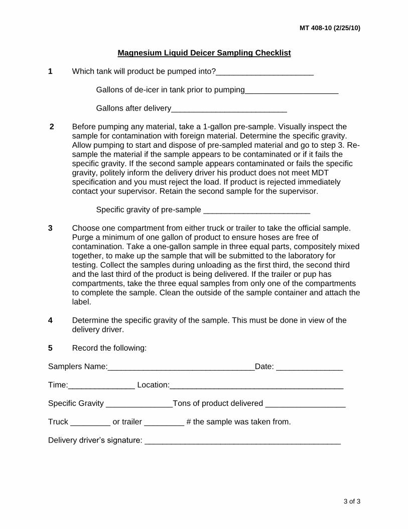
Magnesium Liquid Deicer Sampling Checklist 1 Which tank will product be pumped into?______________________
Gallons of de-icer in tank prior to pumping_____________________
Gallons after delivery__________________________ 2 Before pumping any material, take a 1-gallon pre-sample. Visually inspect the
sample for contamination with foreign material. Determine the specific gravity. Allow pumping to start and dispose of pre-sampled material and go to step 3. Re-sample the material if the sample appears to be contaminated or if it fails the specific gravity. If the second sample appears contaminated or fails the specific gravity, politely inform the delivery driver his product does not meet MDT specification and you must reject the load. If product is rejected immediately contact your supervisor. Retain the second sample for the supervisor.
Specific gravity of pre-sample ________________________
3 Choose one compartment from either truck or trailer to take the official sample.
Purge a minimum of one gallon of product to ensure hoses are free of contamination. Take a one-gallon sample in three equal parts, compositely mixed together, to make up the sample that will be submitted to the laboratory for testing. Collect the samples during unloading as the first third, the second third and the last third of the product is being delivered. If the trailer or pup has compartments, take the three equal samples from only one of the compartments to complete the sample. Clean the outside of the sample container and attach the label.
4 Determine the specific gravity of the sample. This must be done in view of the
delivery driver. 5 Record the following: Samplers Name:_________________________________Date: _______________ Time:_______________ Location:_______________________________________ Specific Gravity _______________Tons of product delivered __________________ Truck _________ or trailer _________ # the sample was taken from. Delivery driver’s signature: ____________________________________________


MT 409-12 (10/01/12)
1 of 1
METHODS OF SAMPLINGB AND TESTING MT 409-12
METHOD OF ACCEPTANCE FOR WELDED STUD SHEAR CONNECTORS
(MONTANA METHOD)
THIS PROCEDURE IS IN DEVELOPMENT


MT 410-04 (06/01/04)
1 of 3
METHODS OF SAMPLING AND TESTING MT 410-04
METHOD OF INSPECTION, SAMPLING, TESTING, AND ACCEPTANCE OF PAINT
(Montana Method) 1 Scope 1.1 This procedure describes the inspection, sampling, testing and acceptance of construction and
maintenance traffic line paint, structural steel primers and finish coats delivered to construction and maintenance projects.
2 Reference Documents
ASTM D711 Standard Test Method for No-Pick-up Times for Traffic Paint D1640 Standard Test Method for Drying, Curing, or Film Formation of Organic Coatings D969 Standard Test Method for Laboratory Determination of Degree of Bleeding of Traffic Paint D1210 Standard Test Method for Fineness of Dispersion of Pigment-Vehicle Systems by
Hegman-Type Gage D562 Standard Test Method for Consistency of Paints Measuring Krebs Unit Viscosity Using a
Stormer-Type Viscometer D823 Standard Practices for Producing Films of Uniform Thickness of Paint, Varnish, and
Related Products on Test Panels D522 Standard Test Methods for Mandrel Bend Test of Attached Organic Coatings D1475 Standard Test Methods for Density of Liquid Coatings, Inks, and Related Products D4060 Standard Test Method for Abrasion Resistance of Organic Coatings by the Taber Abraser MT Materials Manual MT 601 Materials Sampling, Testing, and Acceptance Guide
3 Sampling 3.1 Two samples are required for each lot or batch of paint used on a project. Suitable containers for
each type of paint are listed below. 3.1.1 Sample Waterborne paints using a clean, one-liter (quart), lined, metal can or plastic “Nalgene”
bottle. Do not use unlined metal containers for Waterborne paint samples. 3.1.2 Sample Alkyd paints using a clean, one-liter (quart), unlined, metal “Asphalt” sampling can. Do
not use plastic “Nalgene” containers for Alkyd paint samples. 3.1.3 Sample Epoxy paints using a clean, one-liter (quart), lined or unlined metal can or plastic
“Nalgene” container. 3.1.4 Sample Aluminum Mastic paints using a clean, one-liter (quart), unlined metal “Asphalt” can. Do
not use plastic “Nalgene” containers for Aluminum Mastic paint samples. 3.2 Construction Projects - Project quantities of 19 liters (5 gallons) or less: No field sample required.
Attach the label from the paint container to a Miscellaneous Form 46 and submit to the Materials Bureau.
3.3 Construction Projects - Project quantities greater than 19 liters (5 gallons) but less than 95 liters
(25 gallons): No field sample is required. Sample if the type or quality is suspect, at the option of the Department. Submit Manufacturer's Certification to the Materials Bureau attached to a Miscellaneous Form 45.
3.4 Construction Projects - Project quantities of 95 liters (25 gallons) or more: 3.4.1 Duplicate, one-liter (quart) samples will be taken from the thoroughly mixed contents of a striping
machine or container representing each lot. Both samples will be forwarded to the Materials

MT 410-04 (06/01/04)
2 of 3
Bureau for testing with a Miscellaneous Form 45. Acceptance will be based on the test report issued by the Materials Bureau. CONSTRUCTION PAINT WILL NOT BE PRETESTED AT THE POINT OF MANUFACTURE.
4 Maintenance Traffic Paint 4.1 Duplicate one-liter (quart) samples of thoroughly mixed paint per lot or batch will be sampled by
the Montana Department of Transportation at the point of manufacture and be forwarded to the Materials Bureau for testing. Acceptance will be based on the test report issued by the Materials Bureau.
4.2 For each paint shipment received, a Field Inspection Report - Miscellaneous Material Form No.
46 shall be prepared and mailed to the Materials Bureau. This report shall indicate the type, quantity, and condition of the paint together with source information (Manufacturer and Lot No., etc.). The label may be taken from the container and attached to the inspection report to transmit the source information.
5 Epoxy Pavement Marking Material 5.1 Epoxy pigment and catalyst will be sampled separately and submitted in accordance with 3.1.3
and submit to the Materials Bureau for testing. Manufacturer's certification will be attached to a Miscellaneous Form 45 and submitted with the samples.
6 Thermoplastic Pavement Marking Material 6.1 Thermoplastic will be sampled at the point of application. Approximately ½ kilo (1 pound) of the
solid material will be submitted to the Materials Bureau for testing. The inspector will supply sample containers. Manufacturer's certification will be attached to a Miscellaneous Form 45 and submitted with the samples.
7 Testing 7.1 Test methods used for testing paint shall conform to ASTM, Federal Test Methods Standard No.
141, latest revisions, or tests and methods described below: 7.1.1 Flexibility - Apply the paint to produce a 0.0762 mm (0.003 inch) dry film on a 0.25 mm (0.10") tin
panel. Air dry at twenty-five (25) degrees centigrade plus or minus 2 degrees (25 °C ± 2°C) or 77 degrees Fahrenheit plus or minus 4 degrees (77 °F ± 4 °F) for at least four (4) hours and then bend over 6.4 mm (1/4 inch) diameter mandrel. The film shall not crack when subjected to the above prescribed flexibility test.
7.1.2 Adhesion: Prepare the panel as for the flexibility test. Place the panel on a 3.2 mm (1/8 inch)
thick rubber pad. Strike a sharp blow with a ball peen hammer to cause an indentation of 1.27 mm to 2.54 mm (0.05 to 0.10 inch). There shall be no cracking, chipping or peeling when subjected to the above-prescribed test.
7.1.3 Skinning: In a 250 ml. paint container (1/2 pint), fill 1/2 full with the paint. Examine after 24 hours
for skinning. There shall be no skinning. 7.1.4 Settling: Fill a 100 ml. centrifuge tube with paint and revolve for 2 hrs. at a speed producing a
centrifugal force of 1,112 Newton (250 pounds). A separation of not more than 12.7 mm (1/2 inch) of the pigment is acceptable. The pigment in the bottom of the tube should be soft and easily dispersed with a spatula.
7.1.5 Abrasion: ASTM D4060. 7.1.5.1 Abrasion: Federal Test Method Std. No. 141, Method 6192. Panels may be coated by dipping,
spraying or by means of film applicator. Dry at 25 °C ± 2 °C (77 °F ± 4 °F) for 24 hours, cure at 49 °C (120 °F) for 72 hours, cool to room temperature and subject to Tabor Abrasion Test using CS-10 wheels, 1000 gram load per wheel and at least 500 revolutions. The dry film thickness should not be less than 0.003 inches prior to testing. The Department performs this test starting

MT 410-04 (06/01/04)
3 of 3
with a wet paint thickness of 0.254 mm ± 0.051 mm (0.010 ± 0.002 inch). 7.1.6 Hiding: Use a Standard Horest Hiding Power Chart. Apply at a rate of 16.26 square meters (175
square feet) per 3.785 liters (one gallon). Visual examination will determine acceptance. 7.1.7 Film Appearance: Visual examination of dry film on tin panel is performed. The paint shall dry to
a flat finish. 7.1.8 Light Resistance: Apply a wet film of 0.381 mm (0.012 inches) to two clean 76.2 mm x 127 mm
(3x5 inches) tin panels and allow to dry horizontally for twenty-four (24) hours. Expose one (1) of the panels to direct sunlight or to a carbon arc light (no water spray) for a period equivalent to seven (7) hours of direct sunlight. The other panel shall not be exposed. Finally examine both panels and compare for darkening. The yellow paint shall not darken appreciably when subjected to the above-prescribed test.


MT 412-18 (09/28/18)
1 of 2
METHODS OF SAMPLING AND TESTING
MT 412-18
TOPSOIL SAMPLING, SAMPLE PREPARATION, AND TESTING 1 Scope 1.1 This procedure of sampling and testing topsoil applies to: 1) topsoil imported from another source
(other than the project), and; 2) topsoil intended for use in planting lawns, shrubs, trees or other particular plants (landscaping soil).
1.2 Topsoil that has been stripped and is stockpiled on the project site for later placement on median
areas, outer separation areas, and side slopes of roadway areas (i.e., salvaging and placing) does not need to be tested.
2 Referenced Documents
AASHTO R 90 Sampling Aggregate Products T 88 Particle Size Analysis of Soils T 267 Determination of Organic Content in Soils by Loss on Ignition MT Materials Manual MT 232 Soil Corrosion Test
3 Sampling Procedures 3.1 Samples shall be obtained from each type of soil (homogeneous area). Soil types may be
identified from visual appearance or presence of vegetative growth. 3.1.1 Samples of sub-soils may also be taken from borings in conjunction with a subsurface
investigation. 3.1.2 Samples from stockpiles or from loaded transports may be taken in accordance with procedures
outlined in AASHTO R 90. 3.2 Samples from the layer of soil proposed for use as topsoil shall be labeled “topsoil”. Samples
from the layer of soil over which the topsoil is to be placed shall be labeled “subsoil.” 3.3 A sample shall be a composite of material from three sampling sites. The sampling sites shall
represent similar soils. The sample shall be taken in the following manner. 3.3.1 Dig a v-shaped hole through the thickness of the layer of soil being sampled (if a surface sample)
and remove a ½ inch thick slice of soil from one side of it. 3.3.2 Trim off from each side of the slice all but a thin ribbon of soil down the center of the spade face
and place in a clean bucket. 3.3.3 Repeat Sections 3.3.1 and 3.3.2 two more times. 3.3.4 Mix thoroughly and keep two pounds (2 lbs) for testing. 3.4 Identify the samples by number and the location from which they were taken. Observations
concerning the apparent ability of the soil to support plant growth such as the presence or absence of usual or unusual vegetative types, swamps, rock, salt encrustations, etc., should be noted and recorded with the identification data.

MT 412-18 (09/28/18)
2 of 2
4 Sample Preparation 4.1 Air dry the samples. Remove larger stones by hand and sieve the remainder of the samples
through a 10 mesh (2 mm) sieve. 4.2 Weigh the material retained on the 10 mesh sieve. Determine the percent by weight and record
on the form accompanying the sample(s). This material is considered gravel. 4.3 Submit the minus 10 mesh fraction to the Helena Materials Lab for soils testing. 5 Testing Procedures 5.1 Conductivity – Test topsoil in accordance with MT 232. 5.2 Soil pH – Test topsoil in accordance with MT 232. 5.3 Organic Matter – Test topsoil in accordance with AASHTO T 267. 5.4 Gradation – Test topsoil in accordance with AASHTO T 88.

MT 413-05 (09/01/05)
1 of 2
METHODS OF SAMPLING AND TESTING
MT 413-05 INSPECTION AND TESTING OF FENCING MATERIAL 1 Scope:
1.1 This method is intended to cover the inspection, sampling, and testing of fencing materials. 2 Referenced Documents:
2.1 AASHTO: M 181 Chain Link Fence M 279 Metallic-Coated Steel Woven Wire Fence Fabric M 280 Metallic-Coated (Carbon) Steel Barbed Wire M 281 Steel Fence Posts and Assemblies, Hot-Wrought Materials Manual: MT 404 Method for Inspecting Wood Products
3 General Information:
3.1 Material may be inspected and stored. Acceptable material must be identified by tagging or marking until used.
3.2 Visual inspection of mesh, posts and other parts shall be made for workmanship, dimension,
condition of galvanizing and freedom from defects in accordance with specifications. Galvanizing shall be checked for excessive roughness, blisters, sal ammoniac spots, bruises, and flaking. Care and judgment must be exercised in making this inspection. Weave and finish (knuckling or barbed) of mesh shall be checked for compliance with specifications.
3.3 If gates are included in the order the design, general workmanship, dimensions, and condition of
galvanizing shall be checked for conformance with specifications and applicable drawings. Welded connections shall be inspected to see that they have been cleaned and re-galvanized or painted with approved paint. Whenever practical, materials used and galvanizing procedure shall be checked for compliance with specifications. Observing the fabrication when feasible will be helpful in this regard.
3.4 Samples shall be submitted to the Materials Bureau accompanied by completed Lab. Form No. 45. 3.5 Upon completion of a project, the Project Manager shall submit a report to the Materials Bureau
showing the quantity of each type of material inspected and sampled. 3.6 As a guide to the inspector, all applicable specifications for fencing materials can be found in
Montana Standard Specification for Road and Bridge Construction, Section 712. 4 Chain Link Fence:
4.1 Inspect and sample chain link fence according to AASHTO M 181.
5 Woven Wire: 5.1 Inspect and sample woven wire according to AASHTO M 279.

MT 413-05 (09/01/05)
2 of 2
6 Barbed Wire:
6.1 Inspect and sample barbed wire according to AASHTO M 280. The following is provided as a general guide for field personnel:
6.1.1 Field inspection for General Workmanship: For the purpose of inspection, a maximum of two spools
from the lot shall be inspected for barb length, spacing, overall length, and workmanship. Inspection for barb spacing is normally performed on the outer 25 feet (7.6 m) length of a spool.
Note 1 – Field personnel may measure barb spacing and inspect for general workmanship. When the barb
spacing is measured in the field, the results must be forwarded to the Materials Bureau along with samples for physical testing.
6.1.2 Re-Inspection: If either of the sample spools fails to meet the requirements for barb length,
spacing, overall length, and workmanship, two additional spools shall be selected at random for inspection. If either of these spools fails to meet the requirements, the lot will be rejected.
6.1.3 Sampling: For test purposes, select one spool at random from every 50 spools or fraction thereof in
a lot, or a total of seven samples, whichever is less. A lot shall consist of all the spools of a single construction (Design Number) of barbed wire delivered at the same time.
6.1.4 Test Specimens for Physical Testing: Cut a 4-foot (1.2 m) length of barbed wire from the end of
each spool and submit to the Materials Bureau for testing. The specimen(s) will be tested for mass of coating and breaking strength.
6.1.5 Lot Size for Retests: If one or more of the individual wire specimens fails, retest the lot. For retest
purposes, four additional spools of barbed wire for each 50 spools shall be sampled. The lot size then becomes 50 spools.
7 Hardware for Barbed or Woven Wire:
7.1 Inspection - Stay wires, brace wires, tie wires, and wire clamps shall be inspected for gauge, condition of galvanizing and compliance with specifications. Any tendency of coating to flake off when wire is manipulated should be observed and noted.
8 Steel Fence Posts and Assemblies:
8.1 Inspect and sample steel fence posts and assemblies according to AASHTO M 281.
9 Wood Fence Posts:
9.1 Inspect and sample wood fence posts according to MT 404.

MT 414-09 (06/05/09)
1 of 5
METHODS OF SAMPLING AND TESTING
MT 414-09 METHOD OF ACCEPTANCE FOR REINFORCING STEEL 1 Scope:
1.1 The procedure set forth in this method will be followed for the acceptance of all reinforcing steel. The acceptance will be based on certain documents and random sampling.
2 Referenced Documents:
2.1 AASHTO: M 31 Deformed and Plain Carbon-Steel Bars for Concrete Reinforcement ASTM: A 615 Specification for Deformed and Plain Carbon-Steel Bars for Concrete Reinforcement
3 Required Documents:
3.1 For each shipment of reinforcing steel delivered to the project, the contractor shall furnish two copies each of the following documents to the Project Manager:
3.1.1 Shipping invoice that shows the weight of all the steel in the shipment. Note 1 - In the event the steel does not meet the specification requirements, a copy of the
manufacturer's invoiced price per pound for this material must be provided. 3.1.2 A signed and dated contractors Certificate of Compliance (Form 406).
3.2 A shipment shall consist of the entire amount of reinforcing steel in each truckload delivered to the project. When a shipment is made by railroad, each 20 tons or fraction thereof will be considered a shipment.
3.3 The Project Manager will retain one set of the documents shown above for his files. The other set
will be forwarded to the Materials Bureau after the Project Manager has indicated on the invoice the method by which the steel was accepted. One of the following statements, together with the Project Manager's signature, will be shown on the invoice sent to Helena:
3.3.1 "Shipment accepted on Form 46 and Form 406, no sample taken." 3.3.2 "Shipment accepted on Form 46 and Form 406 and acceptable test results." 4 Random Sample Requirement:
4.1 In addition to the required documents, a minimum random sampling procedure will be adopted. 4.2 As shipments of steel arrive on the project, it will be the responsibility of the Project Manager to
decide how many samples, if any, he will take and when and where they will be taken. Sampling will be done by the contractor as directed by the Project Manager in accordance with MT-601, using table 1 as a guide to indicate the minimum number of samples to be taken.
4.3 The following are locations in the structure where reinforcing steel samples may be taken, or the
remaining portion of the sampled bar may be placed, without adverse effect on the structure. The Bridge Bureau must be contacted if clarification is required on the location of any sample bar.

MT 414-09 (06/05/09)
2 of 5
4 Random Sample Requirement: (continued)
4.3.1 Footing - The outermost bar in the mat may be sampled. The portion of the bar remaining shall be centered in the footing and used as is.
4.3.2 Column - The bar nearest the centerline of bent at centerline of structure may be sampled. The
sample shall be taken from the top end. The remaining portion of the bar may be used as is.
4.3.3 Slab - Transverse Steel - Take sample from bar in bottom layer. Center remaining portion of bar between curbs.
4.3.4 Slab - Longitudinal Steel - Take sample from any line of bars in bottom of slab adjacent to edge
of a beam at the end of slab. 4.3.5 Curb - No sample need be taken. 4.3.6 Bent Cross Beam - The center bar in bottom layer at bottom of beam may be sampled. Center
remaining portion of bar between columns. 4.3.7 T Type Pier Cap - The center bar in bottom layer at top of cap may be sampled. Center
remaining portion of bar over column. 4.3.8 If re-sampling under paragraph 6.1.1.1 becomes necessary because of a failure, it will be
necessary for the contractor to replace the sampled portion plus the required lap length. 4.4 Samples taken will be forwarded immediately to the Materials Bureau for testing in accordance
with ASTM A 615 or AASHTO M 31. 4.5 The shipment under test shall be kept separate from the other steel on the project until test
results have been received. 4.6 Steel taken for the purpose of sampling may have to be replaced in the structure. When
replacement is necessary it shall be done by the contractor at no cost to the State. 5 Domestic Materials:
5.1 No steel will be accepted if it does not comply with Montana Standard Specification for Road and Bridge Construction, Section 106.09.
6 Failing Steel:
6.1 In case there is a failure in any size tested under this random sampling procedure, the steel may be rejected in accordance with 6.1.1 or, a price reduction will be assessed in accordance with 6.1.2.
6.2 The failing steel may be ordered removed and replaced at no cost to the State if either of the two
check samples fail as described in paragraph 6.1.1.1, below. 6.3 In the event that a sample of reinforcing steel fails, two additional samples representing the
sample that failed may be submitted. Both of the check samples must meet specifications before the shipment will be accepted without price reduction.
6.4 If the Bridge Engineer determines that the steel is usable, a price reduction will be assessed
against the contractor. The price reduction will be calculated using the following formula: P = A x B where:

MT 414-09 (06/05/09)
3 of 5
6 Failing Steel: (continued) A = total invoice price of reinforcing steel in the lot.* B = 10%, 20% or 30% dependent upon departure from specifications. The value to be used
shall be determined by the Bridge Engineer. P = Price reduction for the Lot. * A lot is defined as all of the bars of one bar number and pattern of deformation contained in an
individual shipment.
7 Standard Weights, Diameters and Number Designations:
7.1 The standard weights and diameters of deformed reinforcing bars and their number designations shall be those listed in Table 1.
7.1.1 The three minimum yield levels of bars are: 40,000 psi; 60,000 psi; and 75,000 psi, designated
as Grade 40, Grade 60, and Grade 75, respectively. 7.1.2 The nominal dimensions of a deformed bar are equivalent to those of a plain round bar having
the same weight per foot as the deformed bar. 7.1.3 Bar numbers are based on the number of eighths of an inch included in the nominal diameter of
the bars.

MT 414-09 (06/05/09)
4 of 5
TABLE 1
English Version
Bar Size
Nominal Dia.
Inches
Wt. Lb.
Per Ft.
Minimum Sampling Frequency per Project
3 .375 .376 No sample for less than 2 tons 1 sample for ea. 5 tons or fraction
4 .500 .668 No sample for less than 5 tons 1 sample for ea. 40 tons or fraction
5 .625 1.043 No sample for less than 5 tons 1 sample for ea. 40 tons or fraction
6 .750 1.502 No sample for less than 5 tons 1 sample for ea. 85 tons or fraction
7 .875 2.044 No sample for less than 5 tons 1 sample for ea. 85 tons or fraction
8 1.000 2.670 No sample for less than 10 tons 1 sample for ea. 150 tons or fraction
9 1.128 3.400 No sample for less than 10 tons 1 sample for ea. 150 tons or fraction
10 1.270 4.303 No sample for less than 10 tons 1 sample for ea. 240 tons or fraction
11 1.410 5.313 No sample for less than 10 tons 1 sample for ea. 240 tons or fraction
14 1.693 7.650 One sample
18 2.257 13.600 One sample

MT 414-09 (06/05/09)
5 of 5
TABLE 1
Metric Version
Bar Size
Nominal Dia. mm
Wt. Kg/m
Minimum Sampling Frequency per Project
10 9.5 0.560 No sample for less than 2 metric tons (t) 1 sample for ea. 5 metric tons (t)or fraction
13 12.7 0.994 No sample for less than 5 metric tons (t) 1 sample for ea. 36 metric tons (t)or fraction
16 15.69 1.552 No sample for less than 5 metric tons (t) 1 sample for ea. 36 metric tons (t)or fraction
19 19.1 2.235 No sample for less than 5 metric tons (t) 1 sample for ea. 77 metric tons (t)or fraction
22 22.2 3.042 No sample for less than 5 metric tons (t) 1 sample for ea. 77 metric tons (t)or fraction
25 25.4 3.973 No sample for less than 9 metric tons (t) 1 sample for ea. 136 metric tons (t)or fraction
29 28.7 5.060 No sample for less than 9 metric tons (t) 1 sample for ea. 136 metric tons (t)or fraction
32 32.3 6.404 No sample for less than 9 metric tons (t) 1 sample for ea. 218 metric tons (t)or fraction
36 35.8 7.907 No sample for less than 9 metric tons (t) 1 sample for ea. 218 metric tons (t)or fraction
43 43.0 11.38 One sample
57 57.3 20.24 One sample


MT 415-12 (10/01/12)
1 of 1
METHODS OF SAMPLING AND TESTING
MT 415-12 METHOD OF ACCEPTANCE FOR STRUCTURAL STEEL
THIS PROCEDURE IS IN DEVELOPMENT


MT 418-04 (06/01/04)
1 of 1
METHODS OF SAMPLINGB AND TESTING MT 418-04
METHOD OF ACCEPTANCE FOR MISECLLANEOUS WELDED ITEMS
(MONTANA METHOD)
1 Scope: 1.1 This method is intended as a guide for the acceptance of miscellaneous, low stress carrying
welded items. It does not cover any welding in connection with bridge related items.
2 Referenced Documents: 2.1 Montana Department of Transportation Detailed Drawings 3 Field Welding Acceptance: 3.1 The low stress carrying members listed in 3.1.1, 3.1.2, and 3.1.3 below can be approved by the
field provided the welding has been done by a qualified welder in accordance with AWS D1.1 Current edition, Limited Thickness. In the event that field welding is necessary, contact the Bridge Bureau for welder qualification tests.
3.1.1 Trash guard racks (MDT Detailed Drawing No. 615-02) and median inlet covers (MDT Detailed
Drawing No. 604-00).
3.1.2 Guardrail terminal section anchor plates (MDT Detailed Drawing No. 606-86).
3.1.3 Ladders, stairways, scale pit angles, grates, and miscellaneous items associated with weigh stations, rest areas, and observation points.
4 Acceptance Procedure: 4.1 The procedure listed in 4.1.1, 4.1.2, 4.1.3, and 4.1.4 below must be followed for the acceptance
of welded items covered in this method.
4.1.1 A copy of the mill test results must accompany the material.
4.1.2 A copy of the welder qualification form or other verification must accompany the material.
4.1.3 The items must be visually inspected and the welds examined for appearance, size, undercut, and porosity.
4.1.4 Items 4.1.1 and 4.1.2 must be attached to the visual inspection report and submitted in the usual manner.


MT 420-04 (06/01/04)
1 of 3
METHODS OF SAMPLING AND TESTING MT 420-04
PROCEDURE TO CHECK FOR LEAKS UNDER HYDROSTATIC PRESSURE 1 Scope 1.1 This procedure is used to determine the degree of water tightness for corrugated metal irrigation
or siphon pipe and couplers. This test is customarily performed at the fabrication plant, but can also be performed in the field.
2 Apparatus and Equipment 2.1 Bulkheads shall consist of the following: 2.1.1 A two-foot section of corrugated steel pipe of the specific diameter to be tested. Pipe sections
with helical corrugations shall be re-rolled at the outer ends to form at least two corrugations to fully accommodate band couplers.
2.1.2 Two squares pieces of 1/8 inch thick steel plate, with a dimension four inches greater than the
diameter of the pipes to be tested. 2.1.3 Four lengths of 2 inch x 2 inch x ¼ inch steel angles to be used as braces with a length equal to
the dimension of the plates. 2.1.4 One – 3 inch galvanized steel elbow. 2.1.5 One – 3 inch galvanized cap with a ¾ inch threaded hole at center. 2.1.6 One – ¾ inch, or longer, gate valve to accommodate a water hose. 2.1.7 Two full length section of culvert. 2.1.8 Three approved band couplers with appropriate gaskets. 2.1.9 2 inch x 4 inch wood bracing blocks 3 feet in length. 2.2 The bulkheads consist of two 2-foot sections of corrugated steel pipe, of the diameter of the pipe
to be tested, to which a braced 1/8 inch square plate has been welded to one end. One bulkhead is fitted with a 3 inch galvanized elbow. The elbow is welded vertically to the top of the plate. The horizontal leg of the elbow must be located directly below the trough of the culvert corrugation to prevent air entrapment (See Figure 1).
2.3 A 3 inch removable, galvanized filler cap with ¾ inch dia. hole at center is to accommodate a
standpipe for observing the static pressure head applied (see Figure 1 & Figure 2). 2.4 A ¾ inch dia. Gate valve is to accommodate the pressurized hose attached to the bottom of the
steel back plate. This valve is to provide a constant head of water in the stand pipe during the tests and also to serve as a drain after testing is completed (see Figure 1).
2.5 The stand pipe shall consist of the following: 2.5.1 Four – 5 foot sections of ¾ inch galvanized pipe. 2.5.2 Three – ¾ inch galvanized tees. 2.5.3 Three – ¾ inch galvanized plugs. 2.5.4 One – 8 inch funnel.

MT 420-04 (06/01/04)
2 of 3
3 Procedure 3.1 After attaching the bulkheads to the culvert test sections, the sections are coupled together,
braced at the center to prevent sagging, and are filled to capacity with water. 3.2 The 20 foot stand pipe (Figure 2) is assembled and attached to the 3 inch elbow filler cap. 3.3 Water is introduced into the stand pipe from the bottom by means of the gate valve. 3.4 With water flowing continuously out of the first or bottom tee, and after waiting for a period of five
minutes, a close examination is made of the test section for evidence of leakage. 3.5 The tee is plugged and the process repeated at each five foot increment until water flows out of
the top of the stand pipe, the maximum twenty foot head. 3.6 A slight indication of “sweating” or “seepage” at the test seams is permissible for irrigation pipe.
Dripping or free flow of water is not acceptable. No sweating or other seepage for siphon pipe applications is permissible. If only the pipe seams are being tested but not the bands, some leakage at the bands may be allowed.

MT 420-04 (06/01/04)
3 of 3
4 Frequency of Test 4.1 Each diameter of pipe at least once a year at the discretion of the inspector.


MT 421-09 (06/01/09)
1 of 2
METHODS OF SAMPLING AND TESTING MT 421-09
METHOD OF SAMPLING CONSTRUCTION FABRICS 1 Scope 1.1 This method covers the sampling of Geosynthetics. Geosynthetics generally fall into one of the
following categories; woven and non-woven Geotextiles, Geogrids, Geocomposites, Geomembranes and Geosynthetic Clay Liner (GCL).
2 Description 2.1 Geotextiles are permeable materials comprised of fibers or yarns combined into planar textile
structures. The majority are either woven or non-woven (as described below) and are used for strength, separation, drainage, filtration and erosion control purposes.
Woven – Geotextile that are typically made of monofilament, multifilament or fibrillated
yarns. Non-woven – Geotextile that is manufactured using a process in which synthetic polymer
fibers are continuously extruded and spun. The fibers or filaments are then connected by needle punching or heat bonding.
2.2 Geogrid consists of polymer mats constructed either of coated yarns or punched and stretched
polymer sheets that allow interlocking of surrounding geomaterials and are commonly used for soil reinforcement.
2.3 Geocomposites generally consist of a geonet or a cuspated or dimpled polyethylene drainage
core wrapped in a geotextile and are often used as edge drains, wall drains, vertical drains (wick drains), and sheet drains.
2.4 Geomembranes consist of impervious polymer sheets that are typically used to line ponds,
ditches, and landfills. 2.5 Geosynthetic Clay Liners (GCL) are manufactured hydraulic barriers consisting of sodium
bentonite clay sandwiched and binded between two geotextiles or attached with an adhesive to a geomembrane. Overlaps self-seal when the sodium bentonite hydrates. GCL’s are commonly used to control vertical or horizontal infiltration of moisture.
3 Referenced Documents AASHTO M 288 Geotextile Specification for Highway Applications ASTM D4354 Sampling of Geosynthetics for Testing MT Geotechnical Manual 4 Sample 4.1 Prior to installation of the geosynthetic the following requirements are necessary to insure proper
selection for each type of application: 4.1.1 The contractor shall submit to the EPM two copies of a notarized manufacturer's certificate of
compliance signed by a legally authorized official of the manufacturer and notarized. The certification shall represent physical and chemical test results that were performed on a representative lot of material being used by the department.
4.1.2 In addition to certifications, a sample for Acceptance testing is required.
MT 421-09 (06/01/09)
2 of 2
4.1.3 All sampling of geosynthetics,will be done at the project and witnessed by the EPM or his designee, for each type of application, i.e., geotextiles: separation, stabilization, subsurface drainage (Class A, B, or C) permanent erosion control (Class A, B, or C), silt fence (stabilized or unstabilized), geogrids, geocomposites GCL”s and geomembranes. Compare the manufacturer’s certificate of compliance to the specifications for the proposed application to ensure product compliance prior to acceptance and installation. Submit samples with certifications to the Materials Bureau for testing.
4.1.4 The size of sample for each application will be a minimum 4 foot wide strip cut across the full roll
taken from a wrap of geosynthetic not exposed to sunlight or abrasion (see Note 1). 4.1.5 Frequency of sampling shall be one sample for every 10,000 square yards (8,000 m2) of
application. 4.1.5.1 Each new roll used will be checked for variance of lot number and then, if necessary, resampled
and submitted to the Materials Bureau for testing. (See Note 2) 4.1.5.2 The direction of roll must be identified on the sample. Note 1 – The sample must be cut so that the cut edge is perpendicular to the roll (machine) direction. It is
important to identify the roll direction on the sample, as the direction of failure in the fabric must be identified.
Note 2 – Label the sample with the manufacturer's lot number and identification of fabric type, grade or
product name, date of sampling, project number and sample number. 5 Shipment and Storage 5.1 Each geosynthetic roll shall be wrapped with a material that will protect the geosynthetic,
including the ends of the roll, from damage due to shipment, direct sunlight, ultra-violet radiation and contaminants. The protective material shall be maintained during shipping and storage.
5.2 During storage, geosynthetic rolls shall be elevated off of the ground and adequately covered to
protect them from the following: site construction damage, precipitation, extended ultraviolet radiation including sunlight, chemicals that are strong acids or bases, flames including welding sparks, temperatures in excess of 160° F (71° C), and other environmental conditions that may damage the physical properties of the geosynthetic.
6 Specifications 6.1 For basis of acceptance and testing requirements refer to the Standard Specifications for Road
and Bridge Construction. Since the Materials Bureau has a strict acceptance policy, proper sam-pling and correct submittal is essential.

MT 422-12 (04/17/12)
1 of 5
METHODS OF SAMPLING AND TESTING MT 422-12
METHOD OF TEST FOR SURFACE SMOOTHNESS AND PROFILE
1 Scope:
1.1 This method covers the testing of a finished flexible pavement surface for smoothness and profile.
The surface smoothness is expressed in International Roughness Index (IRI) in units of inches per mile. The surface profile is generated to locate variations in profile (e.g., bumps or dips). This method is not intended to be used with rigid pavement or gravel surfacing.
2 Reference Documents:
2.1 Operator’s Manual, Surface Systems & Instruments, LLC
Profiler Operations Manual (POM) for MDT Profilers (most recent version) MDT QC/QA Plan (most recent version)
3 Terminology:
3.1 International Roughness Index (IRI) – An index resulting from a mathematical simulation of vehicular
response to the longitudinal profile of a pavement using a 'quarter-car' simulation model as described in NCHRP Report 228.
4 Apparatus:
4.1 Class I laser road profiler as defined in ASTM E950. The road profiling system is mounted on a
vehicle, usually a van or truck. It consists of the following components: 4.1.1 Vertical, non-contact, height measurement systems (i.e., laser) capable of measuring the height
from the mounted sensor face to the surface of the pavement. 4.1.2 A linear distance measuring system (i.e., DMI) capable of measuring distance traveled. 4.1.3 An inertial referencing system (i.e., accelerometers) capable of measuring the movement of the
vehicle as it traverses the pavement. 5 Software:
5.1 The software must activate the testing using parameters (i.e., data collection initiation) that are
stored by the control setup. 5.2 The software must receive, display, and store raw data received from the profiler. 5.3 The software must be capable of accumulating desired output and printing results. 6 Calibration: 6.1 Perform a comprehensive calibration and sensor check at thirty (30) day intervals during
construction season. Check the DMI and verify Laser each day before use. 6.2 Calibration is used to establish and adjust the operating characteristics of the SSI system. There
are five (5) items that will either be calibrated or checked: laser height, distance measuring device, tire pressure, Accelerometer and Bounce Test.
6.3 Check tire pressure and inflate to manufacturer’s recommended psi. Special care should be given to the tire on which the DMI device is mounted.

MT 422-12 (04/17/12)
2 of 5
6 Calibration: (continued) 6.4 Laser Height Verification
6.4.1 The lasers have been calibrated at the factory. The lasers can only be verified.
6.4.2 A verification check of the laser will be performed each day before use.
6.4.3 A full verification check of the laser sensors must also be performed whenever problems are
suspected, or when a sensor is repaired or replaced. 6.5 Facility for Laser Height Verification
6.5.1 Each MDT District should have a facility available (e.g.; enclosed garage at District). 6.5.2 Facility should have a level surface and be free of vibration. 6.6 Procedure for Laser Height Verification
6.6.1 Verify laser height in accordance with section 3.3 (pages 15-16) of the SSI Operations Manual. 6.7 Accelerometers
6.7.1 Accelerometers need an occasional static verification. Perform static verification (1) every 30 days
during times when the system is used frequently, (2) after any prolonged period that the system has not been used, (3) when repairs are performed on the accelerometer(s) or associated system, or (4) any time the system is generating data that appears erroneous or suspect.
6.8 Facility for Accelerometer Verification
6.8.1 Each MDT District should have a facility available (e.g.; enclosed Garage at District). 6.8.2 Facility should have a level surface and be free of vibration. 6.9 Procedure for Accelerometer Verification 6.9.1 Perform the Accelerometer verification as per section 3.6 (page 21) of the SSI Operations Manual. 6.10 Bounce Test 6.10.1 The bounce test is a controlled-conditions procedure that uses the profiler’s built-in simulation
capabilities to test that the profiling system is operating properly. Perform the bounce test (1) every 30 days during times when the system is used frequently, (2) after any prolonged period that the system has not been used, (3) when repairs are performed on the associated system, or (4) any time the system is generating data that appears erroneous or suspect.
6.11 Facility for Bounce Test 6.11.1 Each MDT District should have a facility available (e.g.; enclosed garage at District).
6.11.2 Facility should have a level surface and be free of vibration. 6.12 Procedure for Bounce Test 6.12.1 Perform the Bounce Test as per sections 3.4 and 3.5 (page 17) of the SSI Operations Manual.

MT 422-12 (04/17/12)
3 of 5
6.13 Distance Measuring Instrument (DMI) 6.13.1 Calibrate DMI whenever problems are suspected, the tires are replaced, suspension repairs are
performed, wheels are rotated/ aligned, or repairs are performed on the DMI. 6.14 DMI Calibration Site
6.14.1 Each MDT District should have a calibration site established. 6.14.2 This site should be located on a straight portion of roadway that is reasonably level and has low
traffic volume. 6.14.3 The site should be measured with a standard surveying tape or wheel (using standard surveying
procedures), or laid out using an electronic distance measuring system.
6.15 Procedure for DMI Calibration 6.15.1 Calibrate the Distance Measuring Instrument (DMI) as per section 3.2 (pages 14-15) of the SSI
Operations Manual.
6.16 Record Keeping
6.16.1 SSI software has a Calibration/Verification Report that Tracks DMI Calibration and Accelerometer
Verification dates. That report may be printed from any Data Analysis files you may have. A simple record of all calibrations and verifications can be kept with the machine as per attached. (SEE “Calibration and Run Information” form)
7 Project Testing:
7.1 Preparation of Surface
7.1.1 Test the roadway only when it is free of moisture and any deleterious material that will not provide
accurate test results. 7.1.2 The Contractor is responsible for all work to prepare the roadway for testing, such as, but not limited
to sweeping off of debris. 7.1.3 Do not conduct testing while it is raining or under other weather conditions determined inclement by
the Engineering Project Manager (EPM). 7.2 Project Setup
7.2.1 Engineering Project Manager (EPM) or one of his/her representatives will meet with the Contractor
and identify the Beginning-of-Project (BOP), the End-of-Project (EOP), and all excluded areas (e.g., bridges not paved, curves with short radii).
7.2.2 If possible, project should be marked for testing using reflective tape or reflective traffic cones. This
is the preferred method. There are two other acceptable methods: back-up to start or manual. 7.2.3 If it is not feasible to use the photocell to initiate and stop data collection, data collection can be
initiated and stopped manually. When manually initiating and stopping profile data collection, cones should be placed at the beginning and end of the project to be used as reference points by the operator.

MT 422-12 (04/17/12)
4 of 5
7.3 Profiler Operations
7.3.1 Operation of profiler should be consistent with guidelines discussed in the latest version of the SSI
Profiler Operations Manual. This includes but is not limited to the following:
• Run in English unit system.
• If possible, initiate data collection via reflective surface and photocell.
• Use approved file naming convention. (Contract#_Lane Direction_Lane_Run#) example 09610_NB_DR_Run1
• Document any issues that occurred during testing.
• Process data with software.
• Properly backup data.
• Provide report to EPM or one of his/her representatives.
7.3.2 MDT collects two comparable runs.
• Once the operator is confident that a minimum of two comparable runs have been obtained, the Quality Control Review and Bump Reports are used to evaluate their acceptability. Profiler runs should satisfy the following criteria:
• The average IRI values at each 1 mi (1.61 km) interval for each of the two runs are within ± 5.7%
of the mean IRI of both runs.
• If spikes (e.g., unusually high IRI) are present in the data, the operator should determine if spikes are pavement related or the result of equipment or operator error. The operator should examine the profile bump reports for discrepancies and features that cannot be explained by observed pavement features.
• Rerun the entire project if any one mile section does not match within the 5.7%
tolerance established in 7.3.2.1.1 and compare that run to the previous runs.
• Use the results of the two runs that compare for project acceptance.
• If the third run does not compare to either of the first two runs, recheck all calibrations and then rerun the entire project and compare the results to the previous runs. Use the two runs that compare favorably.
7.4 Testing Results 7.4.1 Results shall be provided to EPM or one of his/her representatives and shall be processed into
desired segments (e.g., 0.5 miles) as described in the contract Ride Specification. 7.4.2 A Roughness Report will be generated for the first profile run deemed to be within the comparison
values for each lane profiled. This report will contain the IRI values for the left and right wheel paths. These IRI values will be applied to the most recent pay incentives/disincentives as described in Ride Specification.

MT 422-12 (04/17/12)
5 of 5
7.4 Testing Results: (continued) 7.4.3 A Bump Report will be generated for the first profile run deemed to be error free for each lane
profiled. The Bump Report will indicate the locations of potential defects. These will be reviewed with the EPM. Location should be physically examined to determine if, at the EPM’s discretion, the location should be considered a defect.