Embed Size (px)
Citation preview

MCX-RTU Rooftop unit
User Guide

User Guide | MCX-RTU Rooftop
RS8KE102 | 2© Danfoss | ADAP-KOOL® | 2018.11
Contents Document history ........................................................................3Product Introduction...................................................................3Ordering .......................................................................................3Specifications ...............................................................................4Approvals .....................................................................................4Installation ...................................................................................5Connections .................................................................................6Network Topology .......................................................................8Sequence of Operation ...............................................................9
Cooling Mode ..................................................................................... 9Heating Mode ...................................................................................10Dehumidification Mode................................................................10CO2 Mode ..........................................................................................11DOAS Mode .......................................................................................11
Status Screens ............................................................................12Configuration .............................................................................14Overrides ....................................................................................24Schedule Enable ........................................................................25
How it works .....................................................................................25Backup / Restore ........................................................................26
Purpose ...............................................................................................26How it works .....................................................................................26
Using More Than One Zone Sensor ..........................................26Data Logging .............................................................................27
How it works .....................................................................................27Broadcast Configuration ...........................................................28
How it works .....................................................................................28Configure Sensors ...........................................................................28Configure Schedules ......................................................................28Configure Load Shed .....................................................................28
AK-SM 800 MCX-RTU Commission ...........................................29IO List ..........................................................................................34

User Guide | MCX-RTU Rooftop
RS8KE102 | 3© Danfoss | ADAP-KOOL® | 2018.11
Version Init. Date Description
1.00 FF 12/01/15 Initial MCX-RTU User Guide
1.04 FF 7/31/2018 Firmware v1.04 Update
Document history
Product Introduction
The MCX-RTU controller is a complete solution for controlling a small to medium sized commer-cial rooftop unit. The controller provides energy efficient control of the rooftop while maintai-ning designed comfort levels and safety of the controlled space. It is also designed to comple-ment the Danfoss full store control via the connection to the AK-SM 800 series front end.
Ordering Type Function Application Code no.
MCX-RTU Controller for small to medium sized rooftops
Rooftop Controller 080G0304
MCX08M2 Optional additional IO for MCX-RTU IO Expansion 080G0307
MMIGRS2 Optional Remote Display Remote Display 080G0294
User Guide | MCX-RTU Rooftop
RS8KE102 | 4© Danfoss | ADAP-KOOL® | 2018.11
Specifications Supply Voltage 85 – 265 V AC, 50/60 Hz Maximum power consumption: 27 W, 48 VA insulation between power supply and the extra-low voltage: reinforced
Modbus It is important that the installation of the data communication cable be installed correctly. Remember to terminate each end of the bus. EIA485 Rated cable must be used.See separate literature No. RC8AC902.
DO - Digital outputs, 15 pcs. DO1 – DO15 DO1 - DO15, all are mechanical relays, no solid state relays
AO - Analog output, 6 pcs. AO1 – AO6 Outputs are 0 – 10 V DC by default
AI - Analog Inputs, 14 pcs. AI1 – AI14 All temperature sensors default to PT1000, Pressure transducers default to .5 – 4.5 V DC ratiometric with 5 V DC supply. All other inputs are 0 – 5 V DC by default
DI - Digital switch inputs DI1 – DI17 All Dry contacts except DI17 (24 V AC or 230 V AC driven)
AK-SM 800 Firmware required to interface with the MCX-RTU must be VG8.033 or greater and StoreView Desktop version 1.13 or greater must be used for remote access.
Approvals EU Declaration of ConformityThis product is in conformity with the following directive(s), standard(s) or other normative document(s), provided that the product is used in accordance with our instructions.
EMC directive 2014/30/EUBy fulfilling the requirements in the following standardsEN 61000-6-4: 2007 + A1: 2011 Generic standards. Emissions standard for industrial environmentsEN 61000-6-2: 2005 Generic standards. Immunity for industrial environments
andLVD directive 2014/35/EUBy fulfilling the requirements in the following standardsEN60730-1: 2011 Automatic electrical controls for household and similar use. General requirementsEN60730-2-9: 2010 Particular Requirements for Temperature Sensing Controls
andRoHS Directive 2011/65/EUBy fulfilling the requirements in the following standardsEN 50581:2012
UL ApprovalUL file: E31024

User Guide | MCX-RTU Rooftop
RS8KE102 | 5© Danfoss | ADAP-KOOL® | 2018.11
Installation The MCX-RTU is mounted on a DIN rail with enough room to easily connect power and other interface wires.
This image provides the dimensions of the MCX-RTU controller for determining space for mounting. Make sure that you allow enough space for easy routing of the required interface cables for power, inputs and outputs.
110
280 6063
Dan
foss
80G
8044
.01
The MCX-RTU must be mounted in a space that meets the environmental standards named in the specification section of this document.

User Guide | MCX-RTU Rooftop
RS8KE102 | 6© Danfoss | ADAP-KOOL® | 2018.11
Connections
MCX152V - TOP
MCX152V- BOTTOM
STEPPERM
OTO
R 2
RS485-1
SD/M
MC
ST2 4
ST2 3
ST2 2
ST2 1
COM 1
D1 +
D1 -
RS485-2
COM 2
D2 +
D2 -
DIG
ITAL IN
PUT 18
DIG
ITAL O
UTPU
T 9-12D
IGITA
L OU
TPUT 13-15
STEPPER BACKU
P
COM
+ BATT
DIG
ITAL IN
PUT 1-8
DIG
ITAL IN
PUT 9-16
POW
ERSU
PPLY
L
N
MEM
ORY CA
RDA
NA
LOG
OU
TPUT 1-6
AN
ALO
G IN
PUT 1-7
CAN
CAN
-RJETH
ERNET
DIG
ITAL IN
PUT 17
AN
ALO
G IN
PUT 8-14
COM
CANL
CANH
R120
COM 17
DI 17
DIG
ITAL O
UTPU
T 6-8
NO 8
C 8
NO 7
C 7
NO 6
C 6
DIG
ITAL O
UTPU
T 1-5
NO 3
C 3
NO 2
C 2
NO 5
C 5
NO 4
C 4
NO 1
C 1
CAN-RJ
ETH
STEPPERM
OTO
R 1
ST1 4
ST1 3
ST1 2
ST1 1
AO 6
AO 5
AO 4
COM
AO 3
AO 2
AO 1
COM
DI 17H
15V+
COM
DI 9
DI 10
DI 11
DI 12
COM
DI 13
DI 14
DI 15
DI 16
COM
DI 1
DI 2
DI 3
DI 4
COM
DI 5
DI 6
DI 7
DI 8
DI 18H
DI 18
COM 18
C 9
NO 9
C 10
NO 10
C 11
NO 11
C 12
NO 12
C 13
C 13
NO 13
NC 13
C 14
NO 14
NC 14
C 15
NO 15
NC 15
COM
COM
15V+
AI 7
AI 6
AI 5
5V+
AI 4
AI 3
AI 2
AI 1
COM
COM
15V+
AI 14
AI 13
AI 12
5V+
AI 11
AI 10
AI 9
AI 8
Danfoss80G8043.02
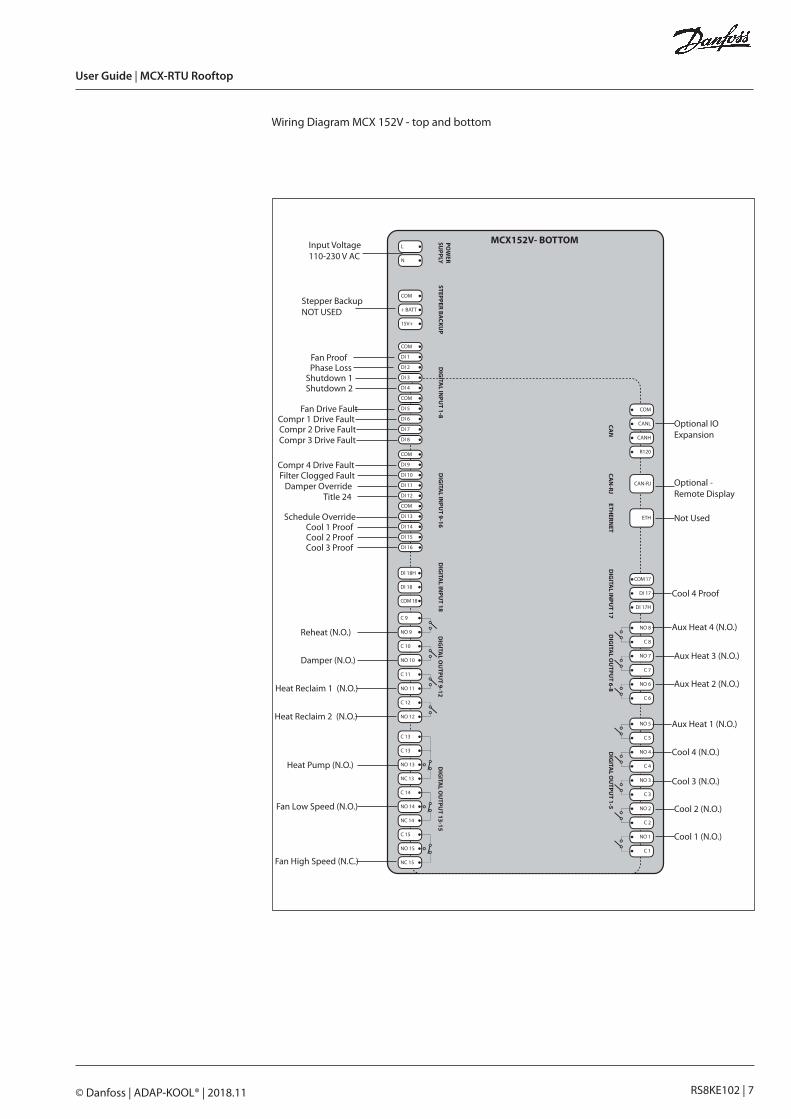
Wiring Diagram MCX 152V - top and bottom
AK-SM 800 Modbus connection
VLT Drive Modbus connection
Mixed Air (PT1000)
Outdoor Temp (PT1000)
Light Level (5VDC)
Compr. 1 Press (5VDC)
Compr. 2 Press (5VDC)
Compr. 3 Press (5VDC)
Compr. 4 Press (5VDC)
Not used
Damper AOVS compressor 4VS compressor 3
VS compressor 1Fan AO
VS compressor 2
DP Outside/Mixed Air
Zone CO2 (0-5V DC)
Outdoor RH (0-5V DC)
Zone RH (0-5V DC)Return Air (PT1000)
Supply Air (PT1000)
Zone Temp(PT1000)
User Guide | MCX-RTU Rooftop
RS8KE102 | 7© Danfoss | ADAP-KOOL® | 2018.11
MCX152V - TOP
MCX152V- BOTTOM
STEPPERM
OTO
R 2
RS485-1
SD/M
MC
ST2 4
ST2 3
ST2 2
ST2 1
COM 1
D1 +
D1 -
RS485-2
COM 2
D2 +
D2 -
DIG
ITAL IN
PUT 18
DIG
ITAL O
UTPU
T 9-12D
IGITA
L OU
TPUT 13-15
STEPPER BACKU
P
COM
+ BATT
DIG
ITAL IN
PUT 1-8
DIG
ITAL IN
PUT 9-16
POW
ERSU
PPLY
L
N
MEM
ORY CA
RDA
NA
LOG
OU
TPUT 1-6
AN
ALO
G IN
PUT 1-7
CAN
CAN
-RJETH
ERNET
DIG
ITAL IN
PUT 17
AN
ALO
G IN
PUT 8-14
COM
CANL
CANH
R120
COM 17
DI 17
DIG
ITAL O
UTPU
T 6-8
NO 8
C 8
NO 7
C 7
NO 6
C 6
DIG
ITAL O
UTPU
T 1-5
NO 3
C 3
NO 2
C 2
NO 5
C 5
NO 4
C 4
NO 1
C 1
CAN-RJ
ETH
STEPPERM
OTO
R 1
ST1 4
ST1 3
ST1 2
ST1 1
AO 6
AO 5
AO 4
COM
AO 3
AO 2
AO 1
COM
DI 17H
15V+
COM
DI 9
DI 10
DI 11
DI 12
COM
DI 13
DI 14
DI 15
DI 16
COM
DI 1
DI 2
DI 3
DI 4
COM
DI 5
DI 6
DI 7
DI 8
DI 18H
DI 18
COM 18
C 9
NO 9
C 10
NO 10
C 11
NO 11
C 12
NO 12
C 13
C 13
NO 13
NC 13
C 14
NO 14
NC 14
C 15
NO 15
NC 15
COM
COM
15V+
AI 7
AI 6
AI 5
5V+
AI 4
AI 3
AI 2
AI 1
COM
COM
15V+
AI 14
AI 13
AI 12
5V+
AI 11
AI 10
AI 9
AI 8
Danfoss80G8043.02
Wiring Diagram MCX 152V - top and bottom
Input Voltage110-230 V AC
Stepper BackupNOT USED
Fan ProofPhase Loss
Shutdown 1Shutdown 2
Fan Drive FaultCompr 1 Drive FaultCompr 2 Drive FaultCompr 3 Drive Fault
Compr 4 Drive FaultFilter Clogged Fault
Damper OverrideTitle 24
Schedule OverrideCool 1 ProofCool 2 ProofCool 3 Proof
Reheat (N.O.)
Damper (N.O.)
Heat Reclaim 1 (N.O.)
Heat Reclaim 2 (N.O.)
Heat Pump (N.O.)
Fan Low Speed (N.O.)
Fan High Speed (N.C.)
Cool 1 (N.O.)
Cool 2 (N.O.)
Cool 3 (N.O.)
Cool 4 (N.O.)
Aux Heat 1 (N.O.)
Aux Heat 2 (N.O.)
Aux Heat 3 (N.O.)
Aux Heat 4 (N.O.)
Cool 4 Proof
Not Used
Optional - Remote Display
Optional IO Expansion

User Guide | MCX-RTU Rooftop
RS8KE102 | 8© Danfoss | ADAP-KOOL® | 2018.11
Network Topology The network cable must be EIA485 rated. The cable is connected from controller to control-ler, and no branches (stars) are allowed on the cable. If the cable length exceeds 1200 meters (1312 yards) a repeater must be inserted. One repeater must be added for every 32 controllers. If the data communication cable runs through an electrically noisy environment which impairs the data signal, one or more repeaters must be added to stabilize the signal. When configuring Modbus devices on the control bus, the highest device address that can be used is 120 (max 120 Modbus control devices in total). The wires are looped from device to device and must observe polarity. A is connected to A and B is connected to B. The shield must be connected and com-plete a path from the device, all controllers, any repeaters finally landed on the ground/shield terminal at the AK-SM 800. The shield must not be connected to earth ground except at the AK-SM 800. At the AK-SM 800 the shield must be attached to the shield terminal and then extended to an external earth ground. See AK-SM 800 User Guide for system 485 wiring instructions. The maximum number of MCX-RTU is dependent on which AK-SM 800 is used.
The AK-SM 880 (080Z4008 and 080Z4009) may use a maximum of 45 MCX-RTU controllers. The AK-SM 820 (080Z4004) may use a maximum of 10 MCX-RTU controllers.
The AK-SM 800 User Manual can be found at: http://food-retail.danfoss.com/knowledge-center/software/ak-sm-800/
Be sure to configure the Modbus repeater AKA 222 (code#084B2240) to the correct baud rate. MCX-RTU baud rate must be set to 38.4 K when used with the AK-SM 800. MCX-RTU cannot be on the same 485 bus with SLVs.
User Guide | MCX-RTU Rooftop
RS8KE102 | 9© Danfoss | ADAP-KOOL® | 2018.11
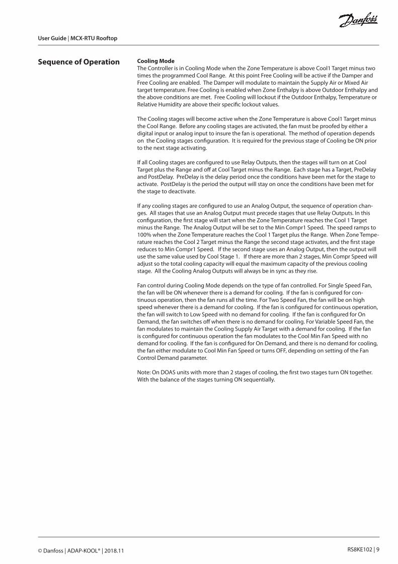
Sequence of Operation Cooling ModeThe Controller is in Cooling Mode when the Zone Temperature is above Cool1 Target minus two times the programmed Cool Range. At this point Free Cooling will be active if the Damper and Free Cooling are enabled. The Damper will modulate to maintain the Supply Air or Mixed Air target temperature. Free Cooling is enabled when Zone Enthalpy is above Outdoor Enthalpy and the above conditions are met. Free Cooling will lockout if the Outdoor Enthalpy, Temperature or Relative Humidity are above their specific lockout values.
The Cooling stages will become active when the Zone Temperature is above Cool1 Target minus the Cool Range. Before any cooling stages are activated, the fan must be proofed by either a digital input or analog input to insure the fan is operational. The method of operation depends on the Cooling stages configuration. It is required for the previous stage of Cooling be ON prior to the next stage activating.
If all Cooling stages are configured to use Relay Outputs, then the stages will turn on at Cool Target plus the Range and off at Cool Target minus the Range. Each stage has a Target, PreDelay and PostDelay. PreDelay is the delay period once the conditions have been met for the stage to activate. PostDelay is the period the output will stay on once the conditions have been met for the stage to deactivate.
If any cooling stages are configured to use an Analog Output, the sequence of operation chan-ges. All stages that use an Analog Output must precede stages that use Relay Outputs. In this configuration, the first stage will start when the Zone Temperature reaches the Cool 1 Target minus the Range. The Analog Output will be set to the Min Compr1 Speed. The speed ramps to 100% when the Zone Temperature reaches the Cool 1 Target plus the Range. When Zone Tempe-rature reaches the Cool 2 Target minus the Range the second stage activates, and the first stage reduces to Min Compr1 Speed. If the second stage uses an Analog Output, then the output will use the same value used by Cool Stage 1. If there are more than 2 stages, Min Compr Speed will adjust so the total cooling capacity will equal the maximum capacity of the previous cooling stage. All the Cooling Analog Outputs will always be in sync as they rise.
Fan control during Cooling Mode depends on the type of fan controlled. For Single Speed Fan, the fan will be ON whenever there is a demand for cooling. If the fan is configured for con-tinuous operation, then the fan runs all the time. For Two Speed Fan, the fan will be on high speed whenever there is a demand for cooling. If the fan is configured for continuous operation, the fan will switch to Low Speed with no demand for cooling. If the fan is configured for On Demand, the fan switches off when there is no demand for cooling. For Variable Speed Fan, the fan modulates to maintain the Cooling Supply Air Target with a demand for cooling. If the fan is configured for continuous operation the fan modulates to the Cool Min Fan Speed with no demand for cooling. If the fan is configured for On Demand, and there is no demand for cooling, the fan either modulate to Cool Min Fan Speed or turns OFF, depending on setting of the Fan Control Demand parameter.
Note: On DOAS units with more than 2 stages of cooling, the first two stages turn ON together. With the balance of the stages turning ON sequentially.

User Guide | MCX-RTU Rooftop
RS8KE102 | 10© Danfoss | ADAP-KOOL® | 2018.11
Heating ModeThe Controller is in Heating Mode when the Zone Temperature is below Cool1 Target minus 2x the Cool Range. Before any heating stages are activated, the fan must be proofed by either a digital input or analog input to insure the fan is operational.
The first type of heating is Heat Reclaim. The first stage of Heat Reclaim will turn on when the Zone Temperature is below Heat Reclaim 1 Target minus the Heat Reclaim Range. The first stage of Heat Reclaim will turn off when the Zone Temperature is above Heat Reclaim 1 Target plus the Heat Reclaim Range. This occurs for each stage of Heat Reclaim. Each stage has their own Target, PreDelay and PostDelay. PreDelay is the delay period once the conditions have been met for the stage to activate. PostDelay is the period the output will stay on once the conditions have been met for the stage to deactivate. It is required that the previous stage of Heat Reclaim be ON prior to the next stage activating.
The first type of heating is the Aux Heat. The first stage of Aux Heat will turn on when the Zone Temperature is below Aux Heat 1 Target minus Aux Heat Range. The first stage of Aux Heat will turn off when the Zone Temperature is above Aux Heat 1 Target plus Aux Heat Range. This will occur for each stage of Aux Heat. Each stage has its own Target, PreDelay and PostDelay. PreDelay is the period the output delays once the conditions have been met for the stage to activate. PostDelay is the period the output will stay on once the conditions have been met for the stage to deactivate. It is required that the previous stage of Aux Heat be ON prior to the next stage activating.
Fan control during Heating Mode depends on the type of fan being controlled. For Single Speed Fan, the fan will be on whenever there is a demand for heating. If configured for continuous operation, then the fan will run all the time. For Two Speed Fan, the fan will be on high speed whenever there is a demand for heating. If the fan is configured for continuous operation, the fan switches to Low Speed when there is no demand for heating. If the fan is configured for On Demand, the fan will switch OFF when there is no demand for heating. For Variable Speed Fan, the fan modulates to maintain the Aux Heat Supply Air Target when there is a demand for heating. If the fan is configured for continuous operation the fan modulates to the Heat Reclaim/Aux Heat Min Fan Speed with no demand for heating. If the fan is configured for On Demand, and there is no demand for heating the fan either modulates to Heat Reclaim/Aux Heat Min Fan Speed or turns OFF depending on the setting of the Fan Control Demand parameter.
Dehumidification ModeThe Controller is in Dehumidification Mode when the Zone RH or Dewpoint is above Dehumi-dification 1 Target plus the Dehumidification Range. Before any dehumidification stages are activated, the fan must be proofed by either a digital input or analog input to insure the fan is operational.
If all Cooling stages are configured to use Relay Outputs, then the Dehumidification stages turn on when the Zone Relative Humidity or Zone Dewpoint is above the Dehumidification Target plus the Range and off at Dehumidification Target minus the Range. Each stage has its own Tar-get, PreDelay and PostDelay. PreDelay is the delay period once the conditions have been met for the stage to activate. PostDelay is the period the output stays on once the conditions have been met for the stage to deactivate.
If any of the Cooling stages are configured to use Analog Outputs, then the Dehumidification stages use a modulating capacity method. The Dehumidification Mode is enabled when the Zone RH or Dewpoint is above Dehumidification 1 Target plus the Dehumidification Range. Once the Dehumidification Mode is enabled the first stage compressor turns on and modulates to maintain the Compressor 1 Target Pressure. Each stage has its own Target and Range used to enable that stage of Dehumidification. If the compressor uses an Analog Output, then the com-pressor modulates to the compressor target pressure. If the compressor uses a Relay Output, then the compressor is turned ON while the stage is enabled. The Dehumidification PreDelay and PostDelay is only used to determine when the Dehumidification Stage is enabled. It does not control the compressors directly.
Fan control during Dehumidification Mode depends on the type of fan being controlled. For Single Speed Fan, the fans ON whenever there is a demand for dehumidification. If the fan is configured for continuous operation, the fan will run all the time. For Two Speed Fan, the fans on high speed whenever there is a demand for dehumidification. If the fan is configured for conti-nuous operation, the fan switches to Low Speed with no demand for dehumidification. If the fan is configured for On Demand, the fan switches OFF when there is no demand for dehumidificati-

User Guide | MCX-RTU Rooftop
RS8KE102 | 11© Danfoss | ADAP-KOOL® | 2018.11
on. For Variable Speed Fan, the fan will run at Cooling Max Fan Speed until all stages of dehumi-dification are running at 100% capacity for the time specified in the Max Capacity Period setting. Once this occurs, the fan modulates trying to lower the compressor capacity to 98%. If the fan is configured for continuous operation the fan modulates to the Cool Min Fan Speed with no demand for dehumidification. If the fan is configured for On Demand, and there is no demand for dehumidification, the fan will either modulate to Cool Min Fan Speed or turn OFF depending on the setting of the Fan Control Demand parameter.
CO2 ModeThe CO2 Mode is for health and safety of everyone in the facility. CO2 Mode has priority over all other modes. And there are no lockouts to effect operation.
CO2 control requires an Analog Output to control the damper. The damper activates when the Zone CO2 level reaches CO2 Target minus the CO2 Range. The damper modulates proportionally between the CO2 Target minus the CO2 Range and CO2 Target plus the CO2 Range.
DOAS ModeDOAS Mode is a combination of all the above modes.
DOAS Mode is controlled by the value for C23 under Setup Options. If set to yes, then the opera-tion is as follows.
Fan Speed is fixed to the value set by parameter FN7 – OvrdFanSpeed(Parameters->Fan)
Outdoor Temperature and Outdoor Relative Humidity are used in place of both the Zone Tempe-rature and Zone Relative Humidity for the Cooling/Heading/Dehumidification modes.
The Damper is set to the DM0(Damper Ovrd Value) value and does not modulate. This value will typically be set to 80%. Note that if this value is less than 100%, and CO2 Mode is calling for the Damper to open more, then the Damper will open to the value requested by the CO2 mode.

User Guide | MCX-RTU Rooftop
RS8KE102 | 12© Danfoss | ADAP-KOOL® | 2018.11
Status Screens
Main Status Screen
What the keys do on the Main Status ScreenEnter – Parameter ScreenESC – Current AlarmsDown Arrow – Current Sensor ValuesLeft Arrow – Broadcast Sensor Values Received
Access Current Sensor Values from Main Status Screen using the Down Arrow button.
Sensor Error Values20000 = Sensor Open20001 = Sensor Short20002 = Broadcast Value Not Updating20003 = Sensor Disabled
Current Sensor Screen
ZNTP – Zone Temp ZNRA – Return Air Temp ZNRH – Zone RH OTTP – Outdoor Temp ZNET – Zone Enthalpy OTRH – Outdoor RH ZNDP – Zone Dewpoint OTET – Outdoor Enthalpy ZNC2 – Zone CO2 Level OTDP – Outdoor Dewpoint ZNSA – Supply Air Temp OCO2 – Outdoor CO2 ZNMA – Mixed Air Temp Cmp1 – Compr 1 Suction Pressure

User Guide | MCX-RTU Rooftop
RS8KE102 | 13© Danfoss | ADAP-KOOL® | 2018.11
Access Broadcast Sensor Values from the Main Status Screen using the Left Arrow button.
Broadcast Sensor Screen
This screen shows the values that have been received via the broadcast from the AK-SM 800. The sensors that start with RH and CO2, are just that. Then you have the three outdoor sensors. The two values at the bottom right are SCHD(Schedules – bit mask) and LDSH(Load Shed Value)

User Guide | MCX-RTU Rooftop
RS8KE102 | 14© Danfoss | ADAP-KOOL® | 2018.11
Configuration The configuration screens are accessed by pressing the Enter button (lower right button) on the controller.
Select Login and enter the password( default: 300) for the following screen. Note that every time the Main Status Screen is visible the password entered is cleared and must be reentered to access the password protected items.
Select Service and then Serial Settings to edit the communication Address of the control.
Press enter to put controller in Edit mode, then use the Up/Down arrows to edit. Press enter to save.

User Guide | MCX-RTU Rooftop
RS8KE102 | 15© Danfoss | ADAP-KOOL® | 2018.11
To configure the controller, go to the Setup Options menu and make selections for your instal-lation. Below is a list of the Setup Options along with their definitions.
OPT Setup Options Function Default Units
C01 Fan Type Select Fan Type – Single Speed, Two Speed or VariSpeed
VS Fan
C02 Fan Control Open Select fan operation during Open periods – Continuous or on Demand
Continuous
C03 Fan Control Closed Select fan operation during Closed periods – Continuous or on Demand
Demand
C04 Fan Proof Select Disable, DI or CT DI
C05 Monitor phase loss Select No or Yes Yes
C06 Cool Stages Select number of cooling stages(0-4) 2
C07 CL1 Stage Size Set size of cooling stage(0.0 – 2000.0) 1000.0
C08 CL1 Stage Type Select RO or AO AO
C09 CL2 Stage Size Set size of cooling stage(0.0 – 2000.0)
C10 CL2 Stage Type Select RO or AO RO
C11 CL3 Stage Size Set size of cooling stage(0.0 – 2000.0)
C12 CL3 Stage Type Select RO or AO RO
C13 CL4 Stage Size Set size of cooling stage(0.0 – 2000.0)
C14 CL4 Stage Type Select RO or AO RO
C15 Heat Reclaim Stages
Select number of Heat Reclaim Stages(0-4) 2
C16 Aux Heat Stages Select number of Aux Heat Stages(0-4) 2
C17 Use Gas Heat Does Aux Heat use Gas Heat(Yes/No) Yes
C18 Enable Dehumidi-fication
Enable Dehumidification(Yes/No) Yes
C19 Control Dehumid on
Select Control Dehumidification with RH sensor or CalcDP
CalcDP
C20 Reheat Cntl Reheat Control(No, AuxRly,HeatReclaim,Both) HtRclm
C21 Reheat Cntrl Sensor
Select Reheat Control Sensor(SupplyAir/Zone-Temp)
SplyAir
C22 Enable Damper Enable Damper using(Disable, DO, or AO) AO
C23 Enthalpy Cntl Enable Enthalpy Control(Yes/No) Yes
C24 Free Cooling Enable Free Cooling(Disable/Enable) Enable
C25 CO2 Option Select CO2 Damper Control(Disable, Monitor, Control)
Control
C26 Damper Cntrl Sensor
Select Damper control sensor(SupplyAir/Mixe-dAir)
SplyAir
C27 Enable HP Valve Enable Heat Pump Valve in None, Heat or Cool Mode
None
C28 Fan Control De-mand
For VS Fan, set fan to Off or Min when no demand
Min
C29 Fan AO Type Select AO Range for Fan(0-5,1-5,0-10,2-10,Custom)
0-10 vdc
C30 Compr1 AO Type Select AO Range for Cool1(0-5,1-5,0-10,2-10,Custom)
1-5 vdc
C31 Compr2 AO Type Select AO Range for Cool2(0-5,1-5,0-10,2-10,Custom)
1-5 vdc

User Guide | MCX-RTU Rooftop
RS8KE102 | 16© Danfoss | ADAP-KOOL® | 2018.11
OPT Setup Options Function Default Units
C32 Compr3 AO Type Select AO Range for Cool3(0-5,1-5,0-10,2-10,Custom)
1-5 vdc
C33 Compr4 AO Type Select AO Range for Cool4(0-5,1-5,0-10,2-10,Custom)
1-5 vdc
C34 Damper AO Type Select AO Range for Damper(0-5,1-5,0-10,2-10,Custom)
2-10 vdc
C35 Custom AO Min Set Min VDC for Custom AO(0.0-10.0vdc) 1.5 vdc
C36 Custom AO Max Set Max VDC for Custom AO(0.0-10.0vdc) 5.0 vdc
C37 Ovrd Night Set-back
If Yes, then Night Setback can be overridden(Yes/No)
No
C42 Invert Fan AO Invert Fan AO(Normal/Invert) Normal
C43 Invert Compr 1 AO Invert Compr1 AO(Normal/Invert) Normal
C44 Invert Compr 2 AO Invert Compr2 AO(Normal/Invert) Normal
C45 Invert Compr 3 AO
Invert Compr3 AO(Normal/Invert) Normal
C46 Invert Compr 4 AO
Invert Compr4 AO(Normal/Invert) Normal
C47 Invert Damper AO
Invert Damper AO(Normal/Invert) Normal
C48 Zone RH Select Sensor for Zone RH(Disable,Local,GlobalRH1-5,Avg)
Local
C49 Zone CO2 Select Sensor for Zone CO2(Disable,Local,GlobalCO2-1-5)
Local
C50 Outdoor Temp Select Sensor for Outdoor Temp(Disable,Local,Global)
Local
C51 Outdoor RH Select Sensor for Outdoor RH(Disable,Local,Global)
Local
C52 Outdoor CO2 Select Sensor for Outdoor CO2(Disable,Local,Global)
Disable
C40 Supply Air Sensor
Select Sensor for Supply Air(Disable,Local) Local
C39 Return Air Sensor
Select Sensor for Return Air(Disable, Local) Local
C38 Mixed Air Sensor Select Sensor for Mixed Air(Disable, Local) Local
C41 Zone Cntl Sensor Zone Control uses the Zone or Return Air sensor
Zone
C53 HT/CL Ctrl Mode Select HT/CL Ctrl Mode(Standard/Supply Air)
Standard
C54 Fan VLT Modbus Enable Fan VLT Modbus Control(Disable/Enable)
Disable
C55 HTReset AO Type Select AO Range for HTReset AO(0-5,1-5,0-10,2-10,Custom)
0-10
C56 Invert HTReset AO
Invert HTReset AO(Normal/Invert)
C57 Zone Control Zone Sensor Config(Single;Average;High;Low)
Single
C58 BldPress Sensor Select Sensor for Building Pressure Control(Disable;Local;Global)
Local
C59 Condenser Cntl Enable AO Condenser Control(No/Yes) No

User Guide | MCX-RTU Rooftop
RS8KE102 | 17© Danfoss | ADAP-KOOL® | 2018.11
Next go to the Parameters menu for the screen below.
The table below shows all the parameters available to edit along with their definitions.
GEN Parameters > General
Function Default Units
y01 ON/OFF Master Switch (Off/On) On
y05 Temperature Units Select Temperature/Pressure Units (C/F)Also sets pressure to BAR when C used, PSI when F used.
F
y06 Reset Runtime/Cycle
Reset Runtime/Cycle values (No/Yes), resets to No once values are cleared
No
y07 Reset to Default Resets all settings to default values (No/Yes), resets to No once values are set to default
No
y08 Night Setback Can be used to put unit into night setback if Select Schedule is zero. (Day/Night)
Day
y27 Load Shed Value Current Load Shed value from front end. (Read Only)
--
y28 Load Shed Set If Load Shed Value is above this setting, unit is placed in Load Shed Mode (0-4, zero disables load shed)
0
y26 Select Schedule If Load Shed Value is above this setting, unit is placed in Load Shed Mode (0-4, zero disables load shed)
0
y29 Select Title24 Select which schedule in the front end the unit will use for night setback.(0-16, zero disables using front end schedule)
0
y09 Enable Alarms Master Alarm Enable (No/Yes) Yes
y10 Changeover Delay Set delay time between switching between Heat and Cool mode. (0-60)
5 m
y02 Enable Expansion Enable Expansion Module (No/Yes) No
y11 Enable AI Filters Enable AI Filters (No/Yes) Yes
y12 Global AI Filter Set Global AI Filter Value (0, 2, 4, 16)How many samples are used to average an AI sensor.
16
y13 Startup Delay Set power up delay before control starts. (5-600) 600 s
y14 MorningStartup-Period
Delay between Night Setback and Normal Mode(0-360
360 m
y15 Sensors Broadcast Number of sensors to broadcast (Read Only)
y16 Broadcast Sensor 1 Select which sensor to broadcast as sensor 1None/ZnRH1-ZnRH5/ZnCO21-ZnCO25/OtdTp/OtdRH/OtdCO2
None
y17 Broadcast Sensor 2 Select which sensor to broadcast as sensor 2None/ZnRH1-ZnRH5/ZnCO21-ZnCO25/OtdTp/OtdRH/OtdCO2
None
y18 Broadcast Sensor 3 Select which sensor to broadcast as sensor 3None/ZnRH1-ZnRH5/ZnCO21-ZnCO25/OtdTp/OtdRH/OtdCO2
None
y19 Broadcast Sensor 4 Select which sensor to broadcast as sensor 4None/ZnRH1-ZnRH5/ZnCO21-ZnCO25/OtdTp/OtdRH/OtdCO2
None
y20 Broadcast Sensor 5 Select which sensor to broadcast as sensor 5None/ZnRH1-ZnRH5/ZnCO21-ZnCO25/OtdTp/OtdRH/OtdCO2
None

User Guide | MCX-RTU Rooftop
RS8KE102 | 18© Danfoss | ADAP-KOOL® | 2018.11
GEN Parameters > General
Function Default Units
y21 Avg RH1 Select RH1 sensor for Average(None/Local/Glbl1-5)
None
y22 Avg RH2 Select RH2 sensor for Average(None/Local/Glbl1-5)
None
y23 Avg RH3 Select RH3 sensor for Average(None/Local/Glbl1-5)
None
y24 Not Used Not Used
y25 Not Used Not Used
y30 SelectExhaustFan Select Exhaust Fan Schedule(0-16) 0
y31 Aux RO 1 Schedule Select Aux RO 1 Schedule(0-16) 0
y32 Aux RO 2 Schedule Select Aux RO 2 Schedule(0-16) 0
y33 Aux RO 3 Schedule Select Aux RO3 Schedule(0-16) 0
y34 Aux RO 4 Sche-dule
Select Aux RO4 Schedule(0-16) 0
y35 Enable Broadcast Enable Broadcast feature(No/Yes) Yes
y36 Night Shutdown Night Shutdown(No/Yes) No
y37 Enable Logging Enable Logging(No/Yes) No
y38 Logging Interval Set Logging Interval 1 m
FAN Parameters > Fan
Function Default Units
FN1 Fan Off Delay Fan Off Delay (0-30) 2 m
FN2 Fan Proof Value Fan Proof Value (0.0-100.0)Used with the Fan CT AI . If AI is above this value the is ON
2.0 a
FN3 Min Fan Speed Min Fan Speed when in Fan Only Mode (0.0-100.0)
30.0 %
FN4 Fan PI Gain Fan PI Gain Value (0.0-100.0) 5.0
FN5 FanPIIntegrati-onTime
Fan PI Integration Time (6-1000) 60
FN6 Building Press Target
Building Pressure Target(-1.00-1.00) 0.00
FN7 OvrdFanSpeed Stage One Fan Speed if exhaust fan one enabled
FN8 OvrdFanHigh Stage Two Fan Speed if exhaust fan two enabled
FN9 Cond Target 1 Condenser Target 350 PSI bar/psi
FNA Cond Target 2 Condenser Target if Reheat enabled 400 PSI bar/psi

User Guide | MCX-RTU Rooftop
RS8KE102 | 19© Danfoss | ADAP-KOOL® | 2018.11
COL Parameters > Cool
Function Default Units
Ct1 CL1 Target Cool 1 Target Temperature (10.0-40.0°C) 40.0 °C/°F
Cb1 CL1 PreDelay Cool 1 Pre Delay (0-240) 0 m
Ca1 CL1 PostDelay Cool 1 Post Delay (0-240) 0 m
Ct2 CL2 Target Cool 2 Target Temperature (10.0-40.0°C) 40.0 °C/°F
Cb2 CL2 PreDelay Cool 2 Pre Delay (0-240) 240 m
Ca2 CL2 PostDelay Cool 2 Post Delay (0-240) 240 m
Ct3 CL3 Target Cool 3 Target Temperature (10.0-40.0°C) 40.0 °C/°F
Cb3 CL3 PreDelay Cool 3 Pre Delay (0-240) 240 m
Ca3 CL3 PostDelay Cool 3 Post Delay (0-240) 240 m
Ct4 CL4 Target Cool 4 Target Temperature (10.0-40.0°C) 40.0 °C/°F
Cb4 CL4 PreDelay Cool 4 Pre Delay (0-240) 240 m
Ca4 CL4 PostDelay Cool 4 Post Delay (0-240) 240 m
CLr CL Range +/- Cool Range +/- (0.0-10.0K) 0.5 K/F
CL1 CL Ambient Lockout
Cool Mode Ambient Lockout (0.0-85.0°C) 15.6 °C/°F
CL2 CL Lockout Range +/-
Cool Mode Ambient Lockout Range +/- (0.0-10.0K)
1.1 K/F
CnS CL Night Setback Cool Mode Night Setback (0.0-30.0K) 0.6 K/F
Cs1 CL SupplyAir Cool Mode Supply Air Target for VS Fan (0.0-100.0°C)
15.0 °C/°F
Cm1 CL Min Fan Speed
Cool Mode Min Fan Speed (0.0-100.0) 50.0 %
Cm2 CL Max Fan Speed
Cool Mode Max Fan Speed (0.0-100.0) 75.0 %
CC1 CL Min Compr 1 Speed
Cool Min Compressor 1 Speed (0.0-100.0) 5.0 %
CC2 CL Min Compr 2 Speed
Cool Min Compressor 2 Speed (0.0-100.0) 30.0 %
CC3 CL Min Compr 3 Speed
Cool Min Compressor 3 speed (0.0-100.0) 30.0 %
CC4 CL Min Compr 4 Speed
Cool Min Compressor 4 speed (0.0-100.0) 30.0 %
CLi PI Integ Time 120
CLg PI Gain 8.0
Cns CL Neutral SA 20.0 °C/°F
Rt1 HR1 Target Heat Reclaim 1 Target Temperature (10.0-40.0°C)
22.2 °C/°F

User Guide | MCX-RTU Rooftop
RS8KE102 | 20© Danfoss | ADAP-KOOL® | 2018.11
HRC Parameters > Heat Reclaim
Function Default Units
Rb1 HR1 PreDelay Heat Reclaim 1 Pre Delay (0-240) 240 m
Ra1 HR1 PostDelay Heat Reclaim 1 Post Delay (0-240) 240 m
Rt2 HR2 Target Heat Reclaim 2 Target Temperature (10.0-40.0°C)
22.2 °C/°F
Rb2 HR2 PreDelay Heat Reclaim 2 Pre Delay (0-240) 240 m
Ra2 HR2 PostDelay Heat Reclaim 2 Post Delay (0-240) 240 m
Rt3 HR3 Target Heat Reclaim 3 Target Temperature (10.0-40.0°C)
20.0 °C/°F
Rb3 HR3 PreDelay Heat Reclaim 3 Pre Delay (0-240) 240 m
Ra3 HR3 PostDelay Heat Reclaim 3 Post Delay (0-240) 240 m
Rt4 HR4 Target Heat Reclaim 4 Target Temperature (10.0-40.0°C)
19.4 °C/°F
Rb4 HR4 PreDelay Heat Reclaim 4 Pre Delay (0-240) 240 m
Ra4 HR4 PostDelay Heat Reclaim 4 Post Delay (0-240) 240 m
HRr HR Range +/- Heat Reclaim Range +/- (0.0-10.0K) 0.2 K/F
HR1 HR Ambient Lockout
Heat Reclaim Mode Ambient Lockout (0.0-85.0°C)
37.8 °C/°F
HR2 HR Lockout Range +/-
Heat Reclaim Mode Ambient Lockout Range +/- (0.0-10.0K)
1.1 K/F
RnS HR Night Set-back
Heat Reclaim Mode Night Setback (0.0-30.0K)
2.8 K/F
HRs HR SupplyAir Heat Reclaim Mode Supply Air Target for VS Fan (0.0-100.0°C)
30.6 °C/°F
Rm1 HR Min Fan Speed
Heat Reclaim Mode Min Fan Speed (0.0-100.0)
50.0 %
Rm2 HR Max Fan Speed
Heat Reclaim Mode Max Fan Speed (0.0-100.0)
75.0 %
HET Parameters > Aux Heat
Function Default Units
Ht1 HT1 Target Aux Heat 1 Target Temperature (10.0-40.0°C)
20.8 °C/°F
Hb1 HT1 PreDelay Aux Heat 1 Pre Delay (0-240) 240 m
Ha1 HT1 PostDelay Aux Heat 1 Post Delay (0-240) 240 m
Ht2 HT2 Target Aux Heat 2 Target Temperature (10.0-40.0°C)
20.3 °C/°F
Hb2 HT2 PreDelay Aux Heat 2 Pre Delay (0-240) 240 m
Ha2 HT2 PostDelay Aux Heat 2 Post Delay (0-240) 240 m
Ht3 HT3 Target Aux Heat 3 Target Temperature (10.0-40.0°C)
18.9 °C/°F
Hb3 HT3 PreDelay Aux Heat 3 Pre Delay (0-240) 240 m
Ha3 HT3 PostDelay Aux Heat 3 Post Delay (0-240) 240 m
Ht4 HT4 Target Aux Heat 4 Target Temperature (10.0-40.0°C)
18.3 °C/°F
Hb4 HT4 PreDelay Aux Heat 4 Pre Delay (0-240) 240 m
Ha4 HT4 PostDelay Aux Heat 4 Post Delay (0-240) 240 m
HTr HT Range +/- Aux Heat Range +/- (0.0-10.0K) 0.5 K/F
HT1 HT Ambient Lockout
Aux Heat Mode Ambient Lockout (0.0-85.0°C)
37.8 °C/°F
HT2 HT Lockout Range +/-
Aux Heat Mode Ambient Lockout Range +/- (0.0-10.0K)
1.1 K/F

User Guide | MCX-RTU Rooftop
RS8KE102 | 21© Danfoss | ADAP-KOOL® | 2018.11
HnS HT Night Set-back
Aux Heat Mode Night Setback (0.0-30.0K) 0.0 K/F
Htd Gas Fan Delay Off
Gas - Fan Delay Off (0-600) 60 s
HTs HT SupplyAir Aux Heat Mode Supply Air Target for VS Fan (0.0-100.0°C)
30.6 °C/°F
Hm1 HT Min Fan Speed
Aux Heat Mode Min Fan Speed (0.0-100.0) 50.0 %
Hm2 HT Max Fan Speed
Aux Heat Mode Max Fan Speed (0.0-100.0) 75.0 %
HTi HT PI Integ Time
HTg Heat PI Gain
HUM Parameters > Dehumd
Function Default Units
Dt1 DH1 Target Dehumidification 1 Target Temperature (10.0-40.0°C)
100.0
Db1 DH1 PreDelay Dehumidification 1 Pre Delay (0-240) 240 m
Da1 DH1 PostDelay Dehumidification 1 Post Delay (0-240) 240 m
Dt2 DH2 Target Dehumidification 2 Target Temperature (10.0-40.0°C)
100.0
HUM Parameters > Dehumd
Function Default Units
Db2 DH2 PreDelay Dehumidification 2 Pre Delay (0-240) 240 m
Da2 DH2 PostDelay Dehumidification 2 Post Delay (0-240) 240 m
Dt3 DH3 Target Dehumidification 3 Target Temperature (10.0-40.0°C)
100.0
Db3 DH3 PreDelay Dehumidification 3 Pre Delay (0-240) 240 m
Da3 DH3 PostDelay Dehumidification 3 Post Delay (0-240) 240 m
Dt4 DH4 Target Dehumidification 4 Target Temperature (10.0-40.0°C)
100.0
Db4 DH4 PreDelay Dehumidification 4 Pre Delay (0-240) 240 m
Da4 DH4 PostDelay Dehumidification 4 Post Delay (0-240) 1000 m
DHr DH Range +/- Dehumidification Range +/- (0.0-10.0K) 10.0
DH1 DH Ambient Lockout
Dehumidification Mode Ambient Lockout (0.0-85.0°C)
100.0 °C/°F
DH2 DH Lockout Range +/-
Dehumidification Mode Ambient Lockout Range +/- (0-10.0K)
10.0 K/F
DnS DH Night Set-back
Dehumidification Mode Night Setback (0.0-30.0K)
30.0
DrT DH Reheat Target
Dehumidification Reheat Target (0.0-40.0°C)
40.0 °C/°F
DrR DH Reheat Range +/-
Dehumidification Reheat Range +/- (0.0-30.0K)
30.0 K/F
DH3 Max_Capacity Period
Period for compressors at max capacity before VS Fan will modulate. (0-60)
2 m
Dp1 Cp1 Press Target Dehumidification Compr 1 Pressure Target (0.0-100.0)
8.2 bar/psi

User Guide | MCX-RTU Rooftop
RS8KE102 | 22© Danfoss | ADAP-KOOL® | 2018.11
HUM Parameters > Dehumd
Function Default Units
Dp2 Cp2 Press Target Dehumidification Compr 2 Pressure Target (0.0-100.0)
8.2 bar/psi
Dp3 Cp3 Press Target Dehumidification Compr 3 Pressure Target (0.0-100.0)
8.2 bar/psi
Dp4 Cp4 Press Target Dehumidification Compr 4 Pressure Target (0.0-100.0)
8.2 bar/psi
Gn1 Cp1 PI Gain Dehumidification Compr 1 PI Gain (0.0-100.0)
10.0
It1 Cp1 Integ Time Dehumidification Compr 1 Integration Time (5-1000)
120
Gn2 Cp2 PI Gain Dehumidification Compr 2 PI Gain (0.0-100.0)
10.0
It2 Cp2 PI Integ Time
Dehumidification Compr 2 Integration Time (5-1000)
120
Gn3 Cp3 PI Gain Dehumidification Compr 3 PI Gain (0.0-100.0)
10.0
It3 Cp3 PI Integ Time
Dehumidification Compr 3 Integration Time (5-1000)
120
Gn4 Cp4 PI Gain Dehumidification Compr 4 PI Gain (0.0-100.0)
10.0
It4 Cp4 PI Integ Time
Dehumidification Compr 4 Integration Time (5-1000)
120
DMP Parameters > Damper Config
Function Default Units
DM1 DAM Min Open Damper Min Open (0.0-100.0) 7.0 %
DM2 DAM Max Open Damper Max Open (0.0-100.0) 100.0 %
DM3 DAM Air Target Damper Free Cooling Supply/Mixed Air Target (0.0-40.0)
18.0 °C/°F
DM4 High Amb Temp Lockout
Damper Free Cooling High Ambient Lock-out (0.0-100.0)
25.0 °C/°F
DM5 High Otdr RH Lockout
Damper Free Cooling High Outdoor RH Lockout (0.0-100.0)
80.0 %
DM6 High Otdr En-thalpyLockout
Damper Free Cooling High Enthalpy Lock-out (0.0-100.0)
60.0
DM7 DM Min Fan Speed
Damper Min Fan Speed (0.0-100.0) 30.0 %
DM8 DM Max Fan Speed
Damper Max Fan Speed (0.0-100.0) 75.0 %
DMa Damper PI Gain Damper Free Cooling Pi Gain (0.0-100.0) 5.0
DMi Damper PI Integ Time
Damper Free Cooling PI Integration Time (5-1000)
60
Dc1 CO2 Target Damper CO2 Target (0-2000) 900 ppm
Dc2 CO2 Range +/- Damper CO2 Range +/- (0-200) 50 ppm
DM0 Ovrd Value 80.0 %
ALM Parameters > Alarm Config
Function Default Units
S01 Fan Proof Delay Fan Proof Alarm Delay (0-15) 5 s
S02 Zone - High Temp
Zone Temp High Alarm (0.0-40.0) 30.0 °C/°F

User Guide | MCX-RTU Rooftop
RS8KE102 | 23© Danfoss | ADAP-KOOL® | 2018.11
ALM Parameters > Alarm Config
Function Default Units
S03 Zone - Low Temp Zone Temp Low Alarm (0.0-40.0) 5.0 °C/°F
S04 Zone - Delay Zone Temp Delay (0-240) 240 m
S05 CO2 - High Level CO2 High Alarm (0-2000) 1000 ppm
S06 CO2 - Delay CO2 Alarm Delay (0-240) 15 m
S07 Fan High Run-time
Fan High Daily Runtime (0-1500) 1500 m
S08 Fan High Cycle Fan High Daily Cycles (0-1000) 1000
S09 Cool1 High Runtime
Cool 1 High Daily Runtime (0-1500) 1500 m
S10 Cool1 High Cycle Cool 1 High Daily Cycles (0-1000) 1000
S11 Cool2 High Runtime
Cool 2 High Daily Runtime (0-1500) 1500
S12 Cool2 High Cycle Cool 2 High Daily Cycles (0-1000) 1000
S13 Cool3 High Runtime
Cool 3 High Daily Runtime (0-1500) 1500 m
S14 Cool3 High Cycle Cool 3 High Daily Cycles (0-1000) 1000
S15 Cool4 High Runtime
Cool 4 High Daily Runtime (0-1500) 1500 m
S16 Cool4 High Cycle Cool 4 High Daily Cycles (0-1000) 1000
S17 Heat1 High Runtime
Heat 1 High Daily Runtime (0-1500) 1500 m
S18 Heat1 High Cycle Heat 1 High Daily Cycles (0-1000) 1000
S19 Heat2 High Runtime
Heat 2 High Daily Runtime (0-1500) 1500 m
S20 Heat2 High Cycle Heat 2 High Daily Cycles (0-1000) 1000
S21 Heat3 High Runtime
Heat 3 High Daily Runtime (0-1500) 1500 m
S22 Heat3 High Cycle Heat 3 High Daily Cycles (0-1000) 1000
S23 Heat4 High Runtime
Heat 4 High Daily Runtime (0-1500) 1500 m
S24 Heat4 High Cycle Heat 4 High Daily Cycles (0-1000) 1000

User Guide | MCX-RTU Rooftop
RS8KE102 | 24© Danfoss | ADAP-KOOL® | 2018.11
OV0 Service > Over-rides
Function Default Units
OV1 Override Night-Setback
Override Night Setback – Enables Night Setback(Off/On)
Off
OV2 Override Title24 Override Title24 – Enables Title24(Off/On) Off
OV3 Override Fan Override Fan(Auto/Override) Auto
OV4 Override Fan % Sets Speed of Fan when in Override(0.0 – 100.0)
0.0 %
OV5 Override Dam-per
Override DamperAuto/Off/25%/50%/75%/100%)
Auto
OV6 Override Cooling Override Cooling(Auto/Off/Stg1/Stg2/Stg3/Stg4/All On)
Auto
OV7 Override Heat Reclaim
Override Heat Reclaim(Auto/Off/Stg1/Stg2/Stg3/Stg4/All On)
Auto
OV8 Override Aux Heat
Override Aux Heat(Auto/Off/Stg1/Stg2/Stg3/Stg4/All On)
Auto
OV9 Override Time-out
Override Timeout – Removes override after so much time (0-30)
0 m
Overrides OV1 and OV2, are used to enable Night Setback and Title24 modes.Overrides OV3 – OV8 are used to place the specific features (as shown below) in manual opera-tion. The override value will be displayed by stage, %, OFF, ON, etc. For analog outputs a value of zero shuts down the feature and 100 will enable 100% of the feature overridden.
Overrides

User Guide | MCX-RTU Rooftop
RS8KE102 | 25© Danfoss | ADAP-KOOL® | 2018.11
How it worksOn the AK-SM 800, select the MCX-RTU to assign a schedule and select the Schedule tab. (Note: it is preferred to set up schedules under configuration -> Refrigeration -> Schedules – see page 28)
If no schedule has been setup, you will see a screen, similar to the one below. If there is no sche-dule the MCX-RTU will follow the configuration of the unit.
To add a schedule, double click on the “Num of schedules” and set the number of schedules. Each schedule allows programming a Start and Stop time.
This On/Off Schedule will completely shutdown the MCX-RTU between midnight and 9:45 AM.
This Eco/Com Schedule will place the MCX-RTU in night setback from 10:00pm to 6:45am.
Schedule Enable

User Guide | MCX-RTU Rooftop
RS8KE102 | 26© Danfoss | ADAP-KOOL® | 2018.11
Backup / Restore PurposeAllows the user to backup/restore the parameters in the MCX-RTU to a SD card.
How it worksThe Backup/Restore feature menu items are located in the Service Menu.
Backup - After you have inserted a SD card into the MCX-RTU, go to the Service Menu and select Backup. Allow a minute for the backup to complete. The backup file is saved to the SD card with the Modbus address of the MCX-RTU as part of the name.
Restore – Insert a SD card that has a backup file on the card. Go to the Service Menu and select Restore. Allow a minute for the restore to complete.Note: There is no indication when the backup/restore are complete.
Using More Than One Zone Sensor
To use more than one zone sensor for a MCX-RTU, use parameter C57(Zone Control).
The allowed settings for this parameter are Single – Only uses a single sensor for control Average – Uses the average of 2 to 3 sensors for control Low – Uses the lowest value of 2 to 3 sensors for control High – Uses the highest value of 2 to 3 sensors for control
To add sensors to the configuration change the function of an unused analog input to either Zone Temp 2 or Zone Temp 3. To change the function, go to Service->IO Config located in the MCX-RTU menu. Then select an unused AI point and edit the FUNC to “Zone Temp 2” or “Zone Temp 3” and set sensor type/min/max values to PT1000/-22.0/338.0.

User Guide | MCX-RTU Rooftop
RS8KE102 | 27© Danfoss | ADAP-KOOL® | 2018.11
Data Logging How it worksLogs the list of points below using the logging interval.). The parameter is located at Parameters->General. Set y37(Logging Interval) to the frequency of logging and y36(Enable Logging). to Yes to start the logging.
Data Log Points1. Zone 1 Zone 1 Sensor2. Zone 2 Zone 2 Sensor(if used)3. Zone 3 Zone 3 Sensor(if used)4. ZoneTemp Zone Temp used for control5. ZoneRH ZoneRH(may be local or global sensor)6. ZoneDewpoint Calculated Zone Dewpoint7. SupplyAir Supply Air Sensor8. ReturnAir Return Air Sensor9. MixedAir Return Air Sensor10. OutdoorAir Outdoor Air Sensor(may be local or global sensor)11. OutdoorRH Outdoor RH Sensor(may be local or global sensor)12. OutdoorDewpoint Calculated Outdoor Dewpoint13. GlobalSchedules Bit map of the first 16 refrigeration schedules14. AlarmStatus Alarm Status15. Mode MCX-RTU Mode16. EffSetp Calculated Setpoint(heat or cool setpoint depending on mode)17. FanOut Fan Control Output18. FanFail Fan Proof not on when FanOut is ON.19. PhaseLoss On means PhaseLoss is good20. ShutdownFlag One of the shutdown DI’s is active21. CoolHeatModeGlobal What is the control mode(0 = Cool, 1 = Heat)22. NightSetback Night Setback is active23. SystemOnOff Master Switch Status24. CoolStatus1 Cool 1 Status25. CoolStatus2 Cool 2 Status26. CoolStatus3 Cool 3 Status27. CoolStatus4 Cool 4 Status28. AuxHeatStatus1 Aux Heat Status 129. AuxHeatStatus2 Aux Heat Status 230. FanStatusAO Fan AO Status – 0-100%31. DamperStatusAO Damper AO Status – 0-100%32. GlobalOutdoorTemp Value of Global Outdoor Temp
The Data Log file may be converted to an Excel file by using the DecodeLog converter program. The program can be requested from Danfoss Tech Support.

User Guide | MCX-RTU Rooftop
RS8KE102 | 28© Danfoss | ADAP-KOOL® | 2018.11
Broadcast Configuration How it worksThe AK-SM 800 scans all the MCX-RTU controllers once a minute for any sensors setup to bro-adcast to all the controllers. If YES the AK-SM 800 requests the current sensor values from the MCX-RTU controllers. Then the SM 800 broadcasts up to 14 sensor values to all the MCX-RTU controllers in one message. Along with the sensor values a Load Shed Value and status for the 16 Schedules are broadcasted twice a minute. All the broadcast settings are within the MCX-RTU parameters, there are no AK-SM 800 settings for this feature.
Configure SensorsSelect the Sensors to Broadcast. On each controller go to Parameters -> General. Then use parameters y16, y17, y18, y19 and y20 to select the sensors that you want to share with the other controllers. Note that each broadcast value may only be used once.
Select the Broadcast Sensors to use on each MCX-RTU controller. On each controller go to Setup Options, then set parameters C48, C49, C50, C51 and C52. These parameters tell the controller whether to use the Local sensor or the Global sensors. You can also use these parameters to disa-ble the sensors.
Configure SchedulesThe schedules used by the MCX-RTU are setup on the AK-SM 800. The schedule status of the first 16 schedules are broadcasted to all the MCX-RTU controllers. There is no assignment of individu-al MCX-RTU at the AK-SM 800. The schedule assignments are only configured in the MCX-RTUs.The schedules at the AK-SM 800 are setup at Configuration->Control->Refrigeration->Schedules. Even though the AK-SM 800 allows for a max of 100 schedules, only the first 16 schedules are broadcast to the MCX-RTU controllers.
To select Schedule for Night Setback at the MCX-RTU go to Parameters->General. Edit setting y26 to the schedule number to control Night Setback.
To select Schedule for Title24, go to Parameters->General. Edit setting y29 to the schedule number you wish to use to control the Title24 option. The Title24 schedule places the controller in Night Setback.
Configure Load ShedTo set Load Shed Setting, go to Parameters->General.
Edit settings y28 to the Load Shed value. If the Load Shed value that is broadcast from the AK-SM 800 is greater than this value, the controller will use Night Setback settings.
See the AK-SM 800 User Manual for details on configuring the AK-SM 800 for Load Shedding.
User Guide | MCX-RTU Rooftop
RS8KE102 | 29© Danfoss | ADAP-KOOL® | 2018.11
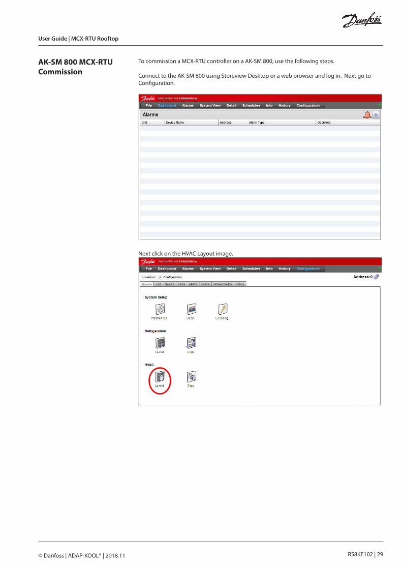
AK-SM 800 MCX-RTU Commission
To commission a MCX-RTU controller on a AK-SM 800, use the following steps.
Connect to the AK-SM 800 using Storeview Desktop or a web browser and log in. Next go to Configuration.
Next click on the HVAC Layout image.
User Guide | MCX-RTU Rooftop
RS8KE102 | 30© Danfoss | ADAP-KOOL® | 2018.11
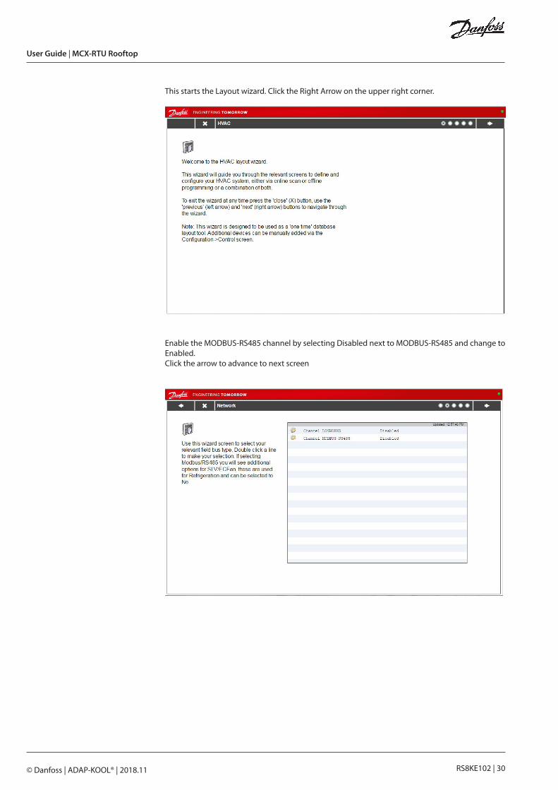
This starts the Layout wizard. Click the Right Arrow on the upper right corner.
Enable the MODBUS-RS485 channel by selecting Disabled next to MODBUS-RS485 and change to Enabled.Click the arrow to advance to next screen

User Guide | MCX-RTU Rooftop
RS8KE102 | 31© Danfoss | ADAP-KOOL® | 2018.11
Click the Scan button to start the scanning process.
Once scanning is complete a list of the HVAC controllers are displayed.Click Right Arrow (upper right corner) to proceed.

User Guide | MCX-RTU Rooftop
RS8KE102 | 32© Danfoss | ADAP-KOOL® | 2018.11
Now add additional offline controllers or proceed. To add offline controllers, follow the instruc-tions on the screen. Click the Right Arrow (upper right corner) to proceed.
View a summary of the HVAC controllers attached to the AK-SM 800. If correct click on the Right Arrow (upper right corner) . If something is missing, click the Left Arrow (upper left corner) and make changes.

User Guide | MCX-RTU Rooftop
RS8KE102 | 33© Danfoss | ADAP-KOOL® | 2018.11
Pop Up indicating completion using HVAC Layout Wizard.

User Guide | MCX-RTU Rooftop
RS8KE102 | 34© Danfoss | ADAP-KOOL® | 2018.11
IO List I/O CONFIGURATION
AI ANALOG INPUTS Min Max Type
1 Zone Temperature -30.0°C 170.0°C PT1000
2 Supply Air -30.0°C 170.0°C PT1000
3 Return Air -30.0°C 170.0°C PT1000
4 Zone RH 0.0 % 100.0 % 0-5 V
5 Outdoor RH 0.0 % 100.0 % 0-5 V
6 Indoor CO2 0 ppm 2000 ppm 0-5 V
7 Building Pressure 0.0 100.0 0-5 V
8 Mixed Air -30.0°C 170.0°C PT1000
9 Outdoor Air -30.0°C 170.0°C PT1000
10 Light Level -1.00 1.00 00-5 V
11 Compr 1 Press 0.0bar 34.5 bar 0-5 V
12 Compr 2 Press 0.0 bar 34.5 bar 0-5 V
13 Compr 3 Press 0.0 bar 34.5 bar 0-5 V
14 Compr 4 Press 0.0 bar 34.5 bar 0-5 V
15 Aux AI 1 (Located on Expansion Module) 0.0 200.0 0-5 V
16 Aux AI 2 (Located on Expansion Module) 0.0 200.0 0-5 V
17 Aux AI 3 (Located on Expansion Module) 0.0 200.0 0-5 V
18 Aux AI 4 (Located on Expansion Module) 0.0 200.0 0-5 V
19 Aux AI 5 (Located on Expansion Module) 0.0 200.0 0-5 V
20 Aux AI 6 (Located on Expansion Module) 0.0 200.0 0-5 V
21 Aux AI 7 (Located on Expansion Module) 0.0 200.0 0-5 V
22 Outdoor CO2 (Located on Expansion Module) 0 2000 0-5 V
DI DIGITAL INPUTS Min Max Type
1 Fan Proof 0 1 N.O.
2 Phase Loss 0 1 N.C.
3 Shutdown 1 0 1 N.O.
4 Shutdown 2 0 1 N.O.
5 Fan Drive Fault 0 1 N.O.
6 Compr1 Drive Fault 0 1 N.O.
7 Compr2 Drive Fault 0 1 N.O.
8 Compr3 Drive Fault 0 1 N.O.
9 Compr4 Drive Fault 0 1 N.O.
10 Filter Clogged Fault 0 1 N.O.
11 Damper Override 0 1 N.O.
12 Title24 Override 0 1 N.O.
13 Schedule Override 0 1 N.O.
14 Cool 1 Proof 0 1 N.O.
15 Cool 2 Proof 0 1 N.O.
16 Cool 3 Proof 0 1 N.O.

User Guide | MCX-RTU Rooftop
RS8KE102 | 35© Danfoss | ADAP-KOOL® | 2018.11
DI DIGITAL INPUTS Min Max Type
17 Cool 4 Proof 0 1 N.O.
18 (Located on Expansion Module) 0 1 N.C.
19 (Located on Expansion Module) 0 1 N.C.
20 (Located on Expansion Module) 0 1 N.C.
21 (Located on Expansion Module) 0 1 N.C.
22 (Located on Expansion Module) 0 1 N.C.
23 (Located on Expansion Module) 0 1 N.C.
24 (Located on Expansion Module) 0 1 N.C.
25 (Located on Expansion Module) 0 1 N.C.
26 (Located on Expansion Module) 0 1 N.C.
AO ANALOG OUTPUTS Min Max Type
1 Fan AO 0 % 100 % 0-10 V
2 VS Compr 1 0 % 100 % 1-5 V
3 VS Compr 2 0 % 100 % 1-5 V
4 VS Compr 3 0 % 100 % 1-5 V
5 VS Compr 4 0 % 100 % 1-5 V
6 Damper AO 0 % 100 % 2-10 V
7 Not Available 0 % 100 % NO
8 Not Available 0 % 100 % NO
9 (Located on Expansion Module) 0 % 100 % NO
10 (Located on Expansion Module) 0 % 100 % NO
11 (Located on Expansion Module) 0 % 100 % NO
12 (Located on Expansion Module) 0 % 100 % NO
DO DIGITAL OUTPUTS Min Max Type
1 Cool 1 0 1 N.O.
2 Cool 2 0 1 N.O.
3 Cool 3 0 1 N.O.
4 Cool 4 0 1 N.O.
5 Aux HT 1 0 1 N.O.
6 Aux HT 2 0 1 N.O.
7 Aux HT 3 0 1 N.O.
8 Aux HT 4 0 1 N.O.
9 Reheat 0 1 N.O.
10 Damper 0 1 N.O.
11 HT RCLM 1 0 1 N.O.
12 HT RCLM 2 0 1 N.O.
13 Heat Pump 0 1 N.O.
14 Fan Low 0 1 N.O.
15 Fan High 0 1 N.C.
16 (Located on Expansion Module) 0 1 N.O.
17 (Located on Expansion Module) 0 1 N.O.
18 (Located on Expansion Module) 0 1 N.O.
19 (Located on Expansion Module) 0 1 N.O.
20 (Located on Expansion Module) 0 1 N.O.
21 (Located on Expansion Module) 0 1 N.O.
22 (Located on Expansion Module) 0 1 N.O.
23 (Located on Expansion Module) 0 1 N.O.

User Guide | MCX-RTU Rooftop
RS8KE102 | 36© Danfoss | ADAP-KOOL® | 2018.11
AD
AP-
KOO
L®
Danfoss can accept no responsibility for possible errors in catalogues, brochures and other printed material. Danfoss reserves the right to alter its products without notice. This also applies to products already on order provided that such alternations can be made without subsequential changes being necessary in specifications already agreed.All trademarks in this material are property of the respective companies. Danfoss and Danfoss logotype are trademarks of Danfoss A/S. All rights reserved.