Embed Size (px)
Citation preview
File Name:
Prepared By:Date:
Revision:
Customer:
Location:
McDONALD’SPage:
01/25/13 MWR/CM
18' ROOF ELEMENT INSTALLATION 6
Note: Color output may not be exact when viewing or printing this drawing. All colors used are PMS or the closest CMYKequivalent. If these colors are incorrect, please provide the correct PMS match and a revision to this drawing will be made. 700 21st Street Southwest
PO Box 210Watertown, SD 57201-02101 .800.843.9888 • www.personasigns.com
DISTRIBUTED BY SIGN UP COMPANY
VARIOUS 1 OF 4
NOTICE:IF PERSONA DOES NOT COORDINATE INSTALLATION, PERSONA CAN NOT BE
HELD RESPONSIBLE FOR ANY VIOLATIONS OF THE SPECIFICATIONS
SET FORTH IN THIS DOCUMENT.THIS DOCUMENT IS FOR BIDDING PURPOSES ONLY. EXACT INSTALLATION PROCEDURES MAY VARY BASED ON SITE SPECIFIC CONDITIONS.
McDONALD’S 18’ ROOF ELEMENT
BOTTOM PLATE DETAIL
4” SQ TUBELEGS
13 ½”
6”
2’-10 3/8”
18’-0 5/16”
3. Verify exact position of RCE on wall ledge with GC and site plan. Arch should be center justified on wall element below. If site conditions do not allow for this, call for further direction.Persona
4. Determine distance from wall to back edge of legs. If necessary, cut off sq tie-back tubes & touch up paint on ends. Ensure there is at least 2” of overlap between the two tie-back sections for bolting together ; tie-back brackets have an adjustable range from 7 ½” - 12” overall length. (see pg 2) Note: smaller tube bracket mounts to the wall. 5. Attach tie-back assemblies to each vertical leg with supplied hardware . See above sketch (see pg 2) for placements. Secure the sleeve sections of tie-back tubes to the desired length (as determined from step 4) & drill one 9/16” hole through both tie back tubes (on each leg). Install shroud back (only) onto tie-back tube on short leg (see shroud assembly sketch). Bolt tubes together with supplied hardware . (see pg 2) Seal all mounting bolts / holes in tie-back assemblies AND openings between 1 ½” and 2” tie-back tubes with silver colored, 1-part polyurethane sealant appropriate for mating surfaces (see pg 4).
6. Using straps and spreader bar, lift element onto wall ledge. Ensure legs are level in both directions. Mark & drill 5/16” pilot holes for base plates (4 per leg). Shim bottom plates (only) with silver painted steel or aluminum, if leg height adjustment is needed. ecure legs to tower with Fill pilot holes with sealant & s ½” x 4” stainless steel lag screws (Persona supplied) or alternative stainless steel hardware for mounting surface (installer to supply, if necessary).
7. Mark & drill 5/16” pilot holes in back wall for tie-back plates . Fill pilot holes with sealant & secure (see pg 2) plates to wall with appropriate hardware (hardware kit supplied by persona). if mounting to corrugated Note: wall surface, see additional instructions on pg 3.
8. Ensure all bolts in base plates & tie back plates are tight. Clean out any debris in & around mounting holes. Fill in entire hole cavity for all mounting bolts using silver colored, 1-part polyurethane sealant appropriate for mating surfaces. Tool sealant smooth to eliminate air pockets & ensure contact to both joint surfaces. Clean off any excess sealant to create finished look . (see pg 4) 9. Install see shroud assembly sketch). Secure shroud front around short leg with supplied hardware ( shroud back to shroud front with supplied screws.
10. Touch up any paint on sign, bolts or structure as required.
11. Clean area & dispose of installation debris off-premise.
X X
X = DISTANCE FROM BOTTOM OF BASE PLATE TO CENTER OF TIE-BACK ASSEMBLY
12” 12”
CL
WALL LEDGE
TIE-BACKASSEMBLY
SHROUD BACK HAS 3” HOLE TO FIT OVER 2” SQ TIE-BACK TUBE
ATTACH SHROUD BACK / COVERTO BENT TABS ON FRONT SECTION, USING PROVIDED #8-18 X 5/8” SQ DRIVEPAN HEAD SCREWS
SHROUD ASSEMBLY
4” SQ RCE LEG
SHROUD FRONT SITSAGAINST FRONT EDGEOF BASE PLATE
RCE INSTALLATION INSTRUCTIONS:
1. Uncrate and inspect element pieces. Notify Persona of any damage. Note: use extreme care when handling / assembling arch piece to avoid causing damage to fiberglass.
2. RCE legs will have plates welded on both ends. Attach legs to arch using supplied bolts.

* ½” X 2 ½” S.S. LAG SCREW W/EXPANDABLE LEAD SHIELD ANCHOR (SEE WALL INSTALL PROFILES) W
ALL SURFACE
MOUNTING PLATE
½” X 1 ½” ZINC PLATED HEX HEAD BOLT & WASHER
MOUNTING PLATE
4” X 4” SQ TUBEVERTICAL RCESUPPORT TUBE
½” FLAT S.S.WASHER
½” X 4” S.S.HEX HEAD
LAG SCREW*
NOTICE:IF PERSONA DOES NOT COORDINATE INSTALLATION, PERSONA CAN NOT BE
HELD RESPONSIBLE FOR ANY VIOLATIONS OF THE SPECIFICATIONS
SET FORTH IN THIS DOCUMENT.THIS DOCUMENT IS FOR BIDDING PURPOSES ONLY. EXACT INSTALLATION PROCEDURES MAY VARY BASED ON SITE SPECIFIC CONDITIONS.
McDONALD’S 18’ ROOF ELEMENT
TIE BACK ASSEMBLY
TIE BACK SECTION FOR ATTACHMENT TO RCEVERTICAL LEG SUPPORT
TIE BACK SECTION FOR ATTACHMENT TO WALL
1 ½” X 1 ½” SQ TUBE
MOUNTING PLATE(SEE PLATE DETAIL)
2” X 2” SQTUBE
MOUNTING PLATE(SEE PLATE DETAIL)
PLATE DETAIL(LEG)
3"
1 ½
"
6"8"
3” X 8” STEEL PLATE
9/16” HOLES
PLATE DETAIL(WALL)
3"
1 ½
"
8 1/4"10 ½"
3” X 10 ½” STEEL PLATE
9/16” X 3” SLOTTEDHOLES
WALL SURFACE
½” FLAT ZINC PLATED WASHER
½” X 3” ZINC PLATED HEX HEAD BOLT& WASHER
½” ZINC PLATED LOCKNUT
MOUNTING PLATE
MOUNTINGPLATE
4” X 4” SQ TUBEVERTICAL RCE
SUPPORT TUBE
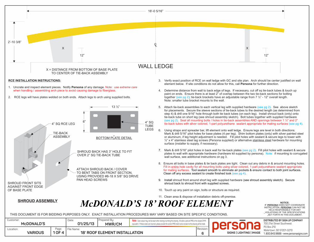
DRILL (1) 9/16” HOLE IN TUBES FOR ½” X 3” BOLT
WOOD WALL INSTALL
TBDPERSITE
CUT TIE-BACK TUBES, IFNEEDED, & PAINT EXPOSED STEEL(NOTE: BRACKETS HAVE ADJUSTABLE RANGE FROM 7 ½” -12” OVERALL LENGTH)
½” X 4” S.S. LAG SCREW & WASHER
SEE PG 1
½” RIVNUTS IN OUTSIDE LEGS FOR ½” BOLTS
SEAL OPENING BETWEENTIE-BACK TUBES WITH SILVER COLORED, 1-PART POLYURETHANE SEALANT APPROPRIATE FOR MATING SURFACES
CMU WALL INSTALL
TBDPERSITE
CUT TIE-BACK TUBES, IFNEEDED, & PAINT EXPOSED STEEL(NOTE: BRACKETS HAVE ADJUSTABLE RANGE FROM 7 ½” -12” OVERALL LENGTH)
½” X 2 ½” S.S. LAG SCREW & WASHER WITH EXPANDABLE LEAD SHIELD ANCHOR SEE
PG 1
½” RIVNUTS IN OUTSIDE LEGS FOR ½” BOLTS
SEAL OPENING BETWEENTIE-BACK TUBES WITH SILVER COLORED, 1-PART POLYURETHANE SEALANT APPROPRIATE FOR MATING SURFACES
File Name:
Prepared By:Date:
Revision:
Customer:
Location:
McDONALD’SPage:
01/25/13 MWR/CM
18' ROOF ELEMENT INSTALLATION 6
Note: Color output may not be exact when viewing or printing this drawing. All colors used are PMS or the closest CMYKequivalent. If these colors are incorrect, please provide the correct PMS match and a revision to this drawing will be made. 700 21st Street Southwest
PO Box 210Watertown, SD 57201-02101 .800.843.9888 • www.personasigns.com
DISTRIBUTED BY SIGN UP COMPANY
VARIOUS 2 OF 4
* ½” X 3 ½” S.S. LAG SCREW W/EXPANDABLE LEAD SHIELD ANCHOR (SEE WALL INSTALL PROFILES)
WALL SU
RFAC
E
½” X 1 ½” ZINC PLATED HEX HEAD BOLT & WASHER
MOUNTING PLATE
4” X 4” SQ TUBEVERTICAL RCESUPPORT TUBE
½” FLAT S.S.WASHER
½” X 5” S.S.HEX HEAD
LAG SCREW*
MOUNTING PLATE
PLACE 3” X 1”Ø GALVANIZED PIPES IN GROOVES OF WALL TO PREVENT PLATE FROM CRUSHING CORRUGATION.BARRIER TAPED SIDE OF PIPE TO BE AGAINST WALL SURFACE. SECURE TOWALL WITH MOUNTINGPLATE BOLTS.
NOTICE:IF PERSONA DOES NOT COORDINATE INSTALLATION, PERSONA CAN NOT BE
HELD RESPONSIBLE FOR ANY VIOLATIONS OF THE SPECIFICATIONS
SET FORTH IN THIS DOCUMENT.THIS DOCUMENT IS FOR BIDDING PURPOSES ONLY. EXACT INSTALLATION PROCEDURES MAY VARY BASED ON SITE SPECIFIC CONDITIONS.
McDONALD’S 18’ ROOF ELEMENT
TIE BACK ASSEMBLY FOR CORRUGATED WALL
TIE BACK SECTION FOR ATTACHMENT TO RCEVERTICAL LEG SUPPORT
2” X 2” SQTUBE
MOUNTING PLATE(SEE PLATE DETAIL)
PLATE DETAIL(LEG)
3"
1 ½
"
6"8"
3” X 8” STEEL PLATE
9/16” HOLES
PLATE DETAIL(WALL)
3"
1 ½
"
8 1/4"10 ½"
3” X 10 ½” STEEL PLATE
9/16” X 3” SLOTTEDHOLES
WALL SU
RFAC
E
½” FLAT ZINC PLATED WASHER
½” X 3” ZINC PLATED HEX HEAD BOLT& WASHER
½” ZINC PLATED LOCKNUT
MOUNTING PLATE
MOUNTINGPLATE
3” X 1” Ø GALVANIZED PIPE
4” X 4” SQ TUBEVERTICAL RCE
SUPPORT TUBE
DRILL (1) 9/16” HOLE IN TUBES FOR ½” X 3” BOLT
5/8” PRE-DRILLEDMOUNTING HOLES
PRE-APPLIED BARRIER TAPE(TO BE PLACED AGAINST WALL SURFACE)
3"
1"
GALVANIZED SPACER PIPE DETAIL
TIE BACK SECTION FOR ATTACHMENT TO WALL
1 ½” X 1 ½” SQ TUBE
MOUNTING PLATE(SEE PLATE DETAIL)
WOOD WALL INSTALL
TBDPERSITE
CUT TIE-BACK TUBES, IFNEEDED, & PAINT EXPOSED STEEL(NOTE: BRACKETS HAVE ADJUSTABLE RANGE FROM 7 ½” -12” OVERALL LENGTH)
½” X 5” S.S. LAG SCREW & WASHER
3” X 1”Ø GALVANIZED PIPES WITH BARRIER TAPEAGAINST WALL SURFACE
SEAL OPENING BETWEENTIE-BACK TUBES WITH SILVER COLORED, 1-PART POLYURETHANE SEALANT APPROPRIATE FOR MATING SURFACES
SEE PG 1
½” RIVNUTS IN OUTSIDE LEGS FOR ½” BOLTS
CMU WALL INSTALL
TBDPERSITE
CUT TIE-BACK TUBES, IFNEEDED, & PAINT EXPOSED STEEL(NOTE: BRACKETS HAVE ADJUSTABLE RANGE FROM 7 ½” -12” OVERALL LENGTH)
½” X 3 ½” S.S. LAG SCREW & WASHER WITH EXPANDABLE LEAD SHIELD ANCHOR
SEE PG 1
½” RIVNUTS IN OUTSIDE LEGS FOR ½” BOLTS
SEAL OPENING BETWEENTIE-BACK TUBES WITH SILVER COLORED, 1-PART POLYURETHANE SEALANT APPROPRIATE FOR MATING SURFACES
3” X 1”Ø GALVANIZED PIPES WITH BARRIER TAPEAGAINST WALL SURFACE
File Name:
Prepared By:Date:
Revision:
Customer:
Location:
McDONALD’SPage:
01/25/13 MWR/CM
18' ROOF ELEMENT INSTALLATION 6
Note: Color output may not be exact when viewing or printing this drawing. All colors used are PMS or the closest CMYKequivalent. If these colors are incorrect, please provide the correct PMS match and a revision to this drawing will be made. 700 21st Street Southwest
PO Box 210Watertown, SD 57201-02101 .800.843.9888 • www.personasigns.com
DISTRIBUTED BY SIGN UP COMPANY
VARIOUS 3 OF 4
NOTICE:IF PERSONA DOES NOT COORDINATE INSTALLATION, PERSONA CAN NOT BE
HELD RESPONSIBLE FOR ANY VIOLATIONS OF THE SPECIFICATIONS
SET FORTH IN THIS DOCUMENT.THIS DOCUMENT IS FOR BIDDING PURPOSES ONLY. EXACT INSTALLATION PROCEDURES MAY VARY BASED ON SITE SPECIFIC CONDITIONS.
McDONALD’S 18’ ROOF ELEMENT
WALL SU
RFAC
E
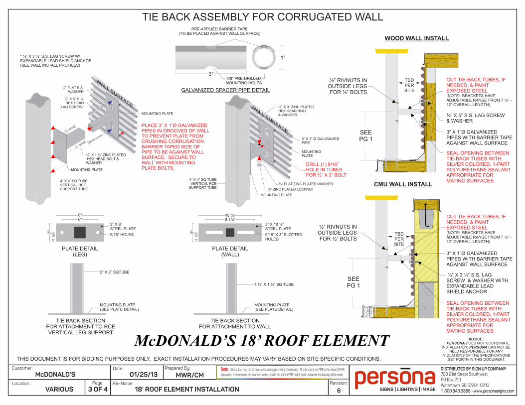
Seal opening between tie back tubes & and mounting bolt / hole
Seal mounting bolt & holes into tie-back leg
Seal mounting bolt & holes in base plate
Seal mounting bolt & holes into wall surface
Clean out any debris in & around mounting holes. Fill in ENTIRE hole cavity for all mounting bolts,
using 1-part polyurethane sealant appropriate for mating surfaces. Tool sealant smooth to eliminate air pockets & ensure contact to both joint surfaces.
Clean off any excess sealant to create finished look
ROOF ELEMENT SEALING INSTRUCTIONS
File Name:
Prepared By:Date:
Revision:
Customer:
Location:
McDONALD’SPage:
01/25/13 MWR/CM
18' ROOF ELEMENT INSTALLATION 6
Note: Color output may not be exact when viewing or printing this drawing. All colors used are PMS or the closest CMYKequivalent. If these colors are incorrect, please provide the correct PMS match and a revision to this drawing will be made. 700 21st Street Southwest
PO Box 210Watertown, SD 57201-02101 .800.843.9888 • www.personasigns.com
DISTRIBUTED BY SIGN UP COMPANY
VARIOUS 4 OF 4