Embed Size (px)
Citation preview

Stanley Access Technologies
MC521 Controller Installation and Operation Manual
Includes Instruction for: DuraGlide™ 2000/3000, 5200/5300, DuraGuard™ and DuraStorm™
Automatic Slide Door Systems 204003
Rev. D 3/11/07
Prohibition on Copying
Any unauthorized reproduction, disclosure or distribution of copies by any person of any portion of this work may be a violation of copyright law of the United States of America and other countries, could result in the awarding of statutory damages of up to $250,000 (17 USC 504) for infringement, and may result in further civil and criminal penalties. All rights reserved.

© 2007, THE STANLEY WORKS. ALL RIGHTS RESERVED. 204003 Rev. D, 3/11/07 1 of 23
Stanley Access Technologies
TABLE OF CONTENTS
1. PURPOSE...................................................................................................................................................... 2 1.1 Discussion.................................................................................................................................................... 2 1.2 Applicability ................................................................................................................................................ 2 2. PREREQUISITES......................................................................................................................................... 2 2.1 Special Items Required................................................................................................................................ 2 3. PRECAUTIONS............................................................................................................................................ 2 4. INSTALLATION INSTRUCTIONS ............................................................................................................ 3 4.1 Installing the MC521 Controller.................................................................................................................. 3 5. WIRING INSTRUCTIONS .......................................................................................................................... 3 5.1 Evaluating Power Requirements.................................................................................................................. 3 5.2 Connecting Main Power Wiring.................................................................................................................. 3 5.3 Connecting Accessories (As Applicable) .................................................................................................... 3 6. TUNE-IN INSTRUCTIONS ......................................................................................................................... 4 6.1 Tuning In the MC521 Controller Using the Palm Pilot............................................................................... 5 6.2 Tuning In the MC521 Controller Using the Controller Pushbuttons........................................................... 8 6.3 Final Tune-In Adjustments ........................................................................................................................ 11 6.4 Spare Parts List .......................................................................................................................................... 12
Attachments Attachment 1, MC521 Controller Controls and Indicators................................................................................. 13 Attachment 2, MC521 System Wiring Diagram................................................................................................. 15 Attachment 3, MC521 Terminal Block Connections —TB1 Through TB5....................................................... 19 Attachment 4, ANSI/BHMA and UL Compliance Requirements for Sliding Doors…………………………..20 Attachment 5, Palm Troubleshooting Aid…………………………………………………….………………..22 Attachment 6, Palm Troubleshooting Screen Descriptions………………………...…………………………..24

© 2007, THE STANLEY WORKS. ALL RIGHTS RESERVED. 204003 Rev. D, 3/11/07 2 of 23
1. PURPOSE
1.1 Discussion This manual provides installation instructions, wiring instructions, and tune-in instructions for the MC521 Controller.
On Dura-Glide sliding doors, the MC521 Controller replaces both the microprocessor control box and the interface board. The door activation devices (SU-100 motion sensors, carpets, push plates, etc.), lock, function switch , doorway holding beams, and door position switches previously connected to the interface board must be connected to the MC521 Controller.
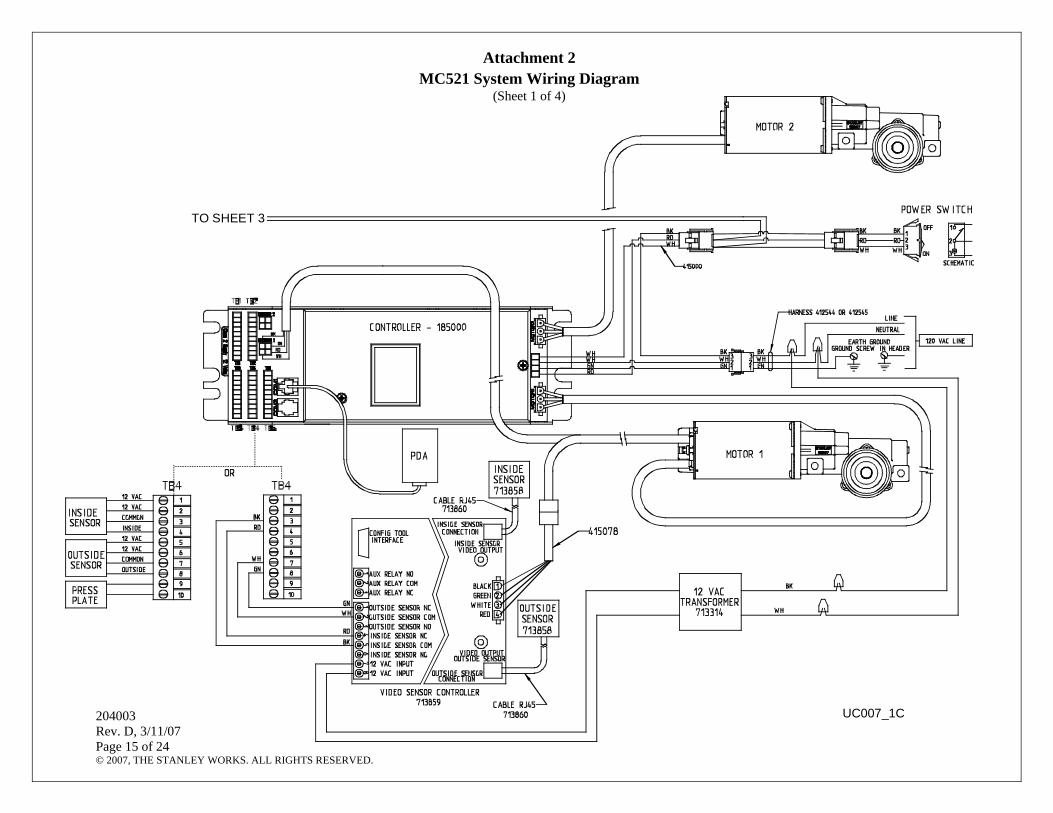
Attachment 1 illustrates the MC521 controller controls and indicators. Attachment 2 illustrates system wiring for Dura-Glide series sliders.
1.2 Applicability This manual is applicable to the Dura-Glide series sliding doors. Instructions for connecting optional accessories are not provided in this manual.
2. PREREQUISITES
2.1 Special Items Required
• Stanley Access Technologies document No. 203975, “Stan Vision Installation and Operation” (if installed)
• Stanley Access Technologies document No. 203957, “SU-100 Motion Sensor Installation and Operation” (if installed)
• SU-100 tune-in remote control (if SU-100 Motion Sensor is installed) • Stanley Access Technologies document No. 203768, “Stanguard™ Threshold Sensor
Installation and Operation” (if installed) • Optex OA-203C manufacturer’s installation and tune-in instructions (if installed) • Palm Programming kit No. 713861 (available from factory) or one of the following
compatible Palm models: M125, 130, 500, 505, 515, Zire 71, Tugsten C, TX, W, T, T2, LifeDrive, and Treo 650, 700p.
• Degreaser • Instructions for any other device to be wired into the MC521 controller.
3. PRECAUTIONS
3.1 All ANSI/BHMA and UL Requirements in Attachment 4 must be met before the door is put into operation.

© 2007, THE STANLEY WORKS. ALL RIGHTS RESERVED. 204003 Rev. D, 3/11/07 3 of 23
4. INSTALLATION INSTRUCTIONS
4.1 Installing the MC521 Controller
NOTE This manual covers new door installations in which the MC521 is factory-installed and wired.
5. WIRING INSTRUCTIONS
5.1 Evaluating Power Requirements
5.1.1 EVALUATE door system power requirements as follows: • ENSURE power source is a dedicated 115 VAC, 50/60 Hz source with 20A
circuit rating. If four operators are used, the source should have a 30A rating. • ENSURE no more than four operators will be connected to one circuit. • ENSURE power source is not shared with other equipment, i.e., cash registers,
EAS systems, or other electromagnetic interference generators.
5.2 Connecting Main Power Wiring
WARNING 1. To prevent injury to personnel, incoming electrical power to the header must be deenergized before
connecting electrical service to the control box. 2. All electrical wiring must conform to National Electrical Code Requirements.
5.2.1 DEENERGIZE incoming electrical power to header. 5.2.2 Refer to Attachment 2, and, using wire nuts, CONNECT incoming line, neutral, and
ground wires to the controller power harness. 5.2.3 IF adhesive wire clamps will be used, DEGREASE metal surfaces on inside of header
cover where clamps will mount. 5.2.4 SECURE wiring to top of the header track tube, and ENSURE the following:
• All wires are clear of belts and belt brackets. • Header cover opens and closes without interference.
5.3 Connecting Accessories (As Applicable)
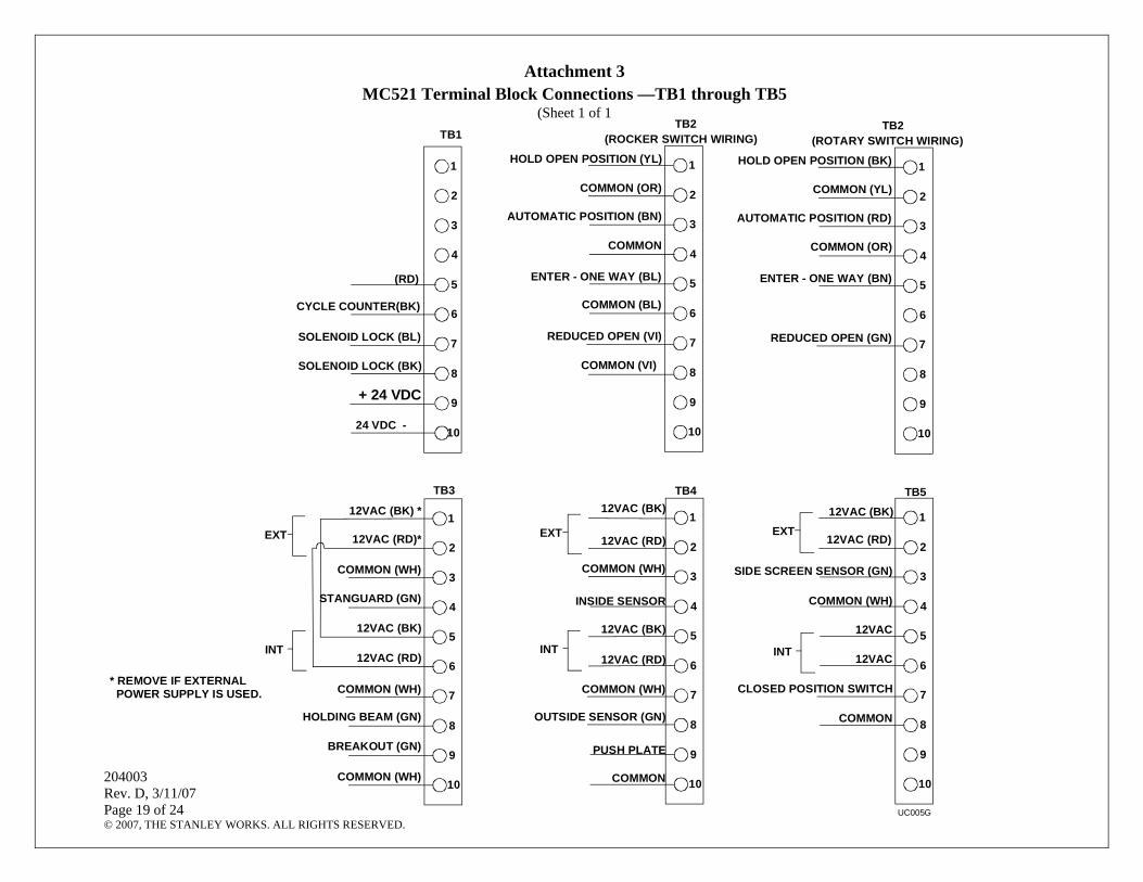
5.3.1 Refer to Attachments 2 and 3, and CONNECT any of the following subsystems to the MC521 controller: • Function switch (rotary, rocker and “POWER” switch wiring) • Stanguard threshold sensor • Doorway holding beam • Cycle counter • Breakout switch • Solenoid lock

© 2007, THE STANLEY WORKS. ALL RIGHTS RESERVED. 204003 Rev. D, 3/11/07 4 of 23
• SU-100 motion sensor(s) wiring (refer to Stanley Document #203957) • OA-203C presence sensor(s) wiring • Push plate wiring • Door position switch closed contact (with door closed) • Stanvision
6. TUNE-IN INSTRUCTIONS
WARNING The door path must be free of objects and remain clear until the First Install Sequence (FIS) is complete. During this sequence the sensors are inactive and the door has no SAFETY. To stop the door, turn power off or put the doors into breakout.
NOTE 1. The MC521 Controller can be tuned-in using a PDA or using the pushbutton switches located on the
controller. Tune-in using the PDA is the preferred method. 2. During normal operation, the digital display indicates status codes. The “UP” and “DOWN”
pushbutton switches can be used to enter and display data values. The user interface values are shown in Tables 2 through 4.
3. If a solenoid lock is installed with no lock circuit board, set Lock Logic to the actual lock type (Fail Safe or Fail Secure). If a Fail Safe or Fail Secure Lock is being installed with a lock circuit board, the Lock Logic must be set to Fail Secure.
4. Handing: Manually open door noting rotation of belt pulleys. If counter clockwise (CCW) use right hand during FIS. If clockwise (CW) use left hand during FIS. See figure below.
5. The first installation sequence (FIS) is used to perform the initial configuration. Upon completion of FIS, all setup parameters are stored in non-volatile memory. Subsequent power cycles will reload the configuration parameters that were configured during FIS.
6. Decimal points on digital display are encoder 1 signals. 7. After changing values, the values must be saved in EEPROM.
PULLEY ROTATES CCWWHILE OPENINGUSE RIGHT HAND IN FIS
PULLEY ROTATES CWWHILE OPENINGUSE LEFT HAND IN FIS
RIGHT HAND
LEFT HAND
HANDING

© 2007, THE STANLEY WORKS. ALL RIGHTS RESERVED. 204003 Rev. D, 3/11/07 5 of 23
6.1 Tuning In the MC521 Controller Using the Palm Pilot
NOTE The following steps provide instructions for tuning the MC521 controller using the Palm Pilot. MC521 application software is required. Connect Palm to MC521 controller, turn on header POWER switch, and perform the following steps.
Step 1: Select MC521 Tool Box from the list of applications.
Step 2: Select Restart FIS on the Main selection menu. (FIS = First Install Sequence) Note: Firmware is the software revision. Cycles are door cycles in memory and are only accurate on revision C (5.19) and higher.
Step 3: Select Duraglide.
Step 4: Select applicable Switch Type, Motor Setup, and Motor Handing.
Step 5: If additional configuration is needed press Configure Door.
Step 6: Configure additional settings and press Update after each setting has been changed. Once completed, press Cancel to go back to the Main selection menu.

© 2007, THE STANLEY WORKS. ALL RIGHTS RESERVED. 204003 Rev. D, 3/11/07 6 of 23
Step 7: Press Begin AutoConfigure
Step 8: Press OK.
Step 9: Put door fuction switch to Hold Open then immediately back to Closed. The same function can be done remotely from the Palm by pressing Operate.
r
Step 10: For all doors except cart doors press Motor 1 to operate and have door(s) move. For cart doors, press Motor 2 when configuring the second door.
WARNING: During this sequence the sensors are inactive and the door has no SAFETY. To stop the door, turn power off or put the doors into breakout. Step 11: Door will go through a learn sequence to configure itself. The door will perform the following operations in learn mode:
• Open fully at check speed. • Close fully at check speed. • Open at full speed halfway and stop. • Open fully in check speed. • Close at close speed halfway and stop. • Finish closing at check speed.
Step 12: If the door is not operating correctly select Trouble Shoot to enter the Trouble Shooting menu.

© 2007, THE STANLEY WORKS. ALL RIGHTS RESERVED. 204003 Rev. D, 3/11/07 7 of 23
Step 13: View the I/O grid to verify the sensors and inputs. Dark indicates input/output contact is closed. Light indicates input/output contact is open. Gray never changes.
Step 14: Press More> to access more functions.
Step 15: Press Clone Settings to pull all of the settings out of one controller and put them into another door.
Step 16: To pull all of the settings out of one controller and put them into another door, press Fetch Settings. Notes: The Fetch Settings feature will only work if both doors are the same and both doors have the same software version. FIS must be performed on controllers before Push Settings can be used.
To put the settings into another controller, plug the Palm into the other controller and press Push Settings. Note: The Push Settings feature will only work if both doors are the same and both doors have the same software version.
Step 17: Press Summary Listing to view all current settings.

© 2007, THE STANLEY WORKS. ALL RIGHTS RESERVED. 204003 Rev. D, 3/11/07 8 of 23
Step 18: Review the information on the summary listing.
6.2 Tuning In the MC521 Controller Using the Controller Pushbuttons
NOTE 1. To change the INDEX:
Hold ENTER switch while pressing UP or DOWN to get to desired INDEX
2. To change a VALUE: Unlock the keypad by setting index 99 to value 01. After the desired INDEX is selected, release ENTER and within 2.5 seconds press UP or DOWN
to get the desired VALUE. (If the the UP or DOWN buttons are not pressed within 2.5 seconds of releasing the ENTER button, the display will change from the VALUE back to the STATUS.)
3. To display STATUS CODE: A few seconds after the VALUE is selected, the display indicates the STATUS CODE
4. To show the INDEX and VALUE To show the INDEX, hold ENTER. Once ENTER is released the display will show the VALUE of
that INDEX.
5. Read the descriptions entirely before performing each step. Check the INDEX and VALUE after each step.
6. To store changes in permanent memory: Cycling door open one time will store changes. 7. To lock keypad: Lock keypad by setting index 99 to value 01 or by turning power OFF and then ON. 8. To access the door cycle counter function: a. Ensure that the keypad is locked by setting index 99 to 01. b. Ensure that the index is set to any index but 99. c. Press the up or down key to access the door cycle counter. d. The display will show “dc” followed by four pairs of digits, followed by “dc”. For example, if the door count was 12345678 cycles the controller will display “dc” “12” “34” “56” “78” “dc”.

© 2007, THE STANLEY WORKS. ALL RIGHTS RESERVED. 204003 Rev. D, 3/11/07 9 of 23
Table 1. FIS Procedure using Pushbuttons Display
Step Description Index Value Status Code
1 Set Function switch to “Closed.” 2 Turn power on. 3 Unlock keypad. 99 00 00 4 Restart FIS. 96 01 A0 5 Select door type: Slide, 01 single motor or 02 dual motor. 00 01 (single)
02 (dual) A0
6 Select handing: 00 Right or 01 Left. Manually open door noting rotation of belt pulleys. If counterclockwise (CCW) use right hand during FIS. If clockwise (CW) use left hand during FIS.
01 00 (right) 01 (left)
A0
7 Accept FIS. As soon as the VALUE is changed to 01, display will go to 20 (Open Speed value) and then to A1. (Note: 20 is the default value.) When A1 is displayed go to next step.
03 01 A1
8 Make changes: Function switch 01 Rocker or 00 Rotary. The INDEX will start at 00.
11 01 rocker 00 rotary
A1
9 Select Lock Logic: Lock Logic, 00 = Fail Safe; 01 = Fail Secure. Note: For locks with circuit board, set to 01 Fail Secure. For locks with no circuit board, set to Fail Safe or Fail Secure.
07 00 Fail Safe 01 Fail Secure
10 WARNING: During this sequence the sensors are inactive and the door has no SAFETY. To stop the door, turn power off or put the doors into breakout. Function switch: Switch to OPEN, momentarily, then CLOSED/LOCKED. Wait for the learn sequence to end. Display will show A2 when finished.
A2
11 Lock keypad. 99 01 00 12 Final Tune in.
Table 2. Index List
Index Description 00-89 Settings Values, see Table 3. 90-95 Reserved.
96 Command – Restart FIS. Entering “01” will cause FIS to restart. 97 Firmware – Entering “01” will display “FE” followed by two pairs of digits followed by “FE”. For
example, if the firmware was 0609 the controller will display “FE” “06” “09” “FE”. 98 Command – Restart auto configuration. Entering “01” will cause auto configuration. 99 Command – Lock. Entering “01” will lock all value inputs except this index. This prevents
inadvertent changes to input values. Values may be unlocked by entering “00” in this index.

© 2007, THE STANLEY WORKS. ALL RIGHTS RESERVED. 204003 Rev. D, 3/11/07 10 of 23
Table 3. Settings
Defaults Index Min. Value
Max. Value
Description Single Dual
00 05 35 Open speed, increment by 1. 20 20 01 05 12 Close speed, revolutions per second. 10 10 02 03 10 Check speed, revolutions per second. 04 04 03 00 99 Open check length, percent of full opening. -- -- 04 00 99 Close check length, percent of full opening. -- -- 05 00 99 Reduced open position, percent of full opening (00=full
open, 99=full close). -- --
06 01 99 Hold open delay (0 to 25 sec.). 03 03 07 00 01 Lock Logic, 01 = Fail Secure, 00 = Fail Safe Note: For
locks with circuit board, set to 01 Fail Secure. For locks with no circuit board, set to Fail Safe or Fail Secure.
01 01
08 00 99 Open torque, percent of full scale. 33 33
09 00 99 Close torque, percent of full scale. 22 15 10 00 99 Check torque, percent of full scale. 24 15 11 00 02 Dura-Glide function switch type: 00=double pole rotary,
01=rocker, 02=single pole rotary (Single pole rotary not available until further notice).
01 01
12 00 01 2S Operation, 0=off, 1=on 00 00 13 01 99 Obstruction Time Delay (.01 – 2.55 sec) Heavy and dual
motor doors may require a longer obstruction time (45 on buttons or 1.0 sec. on Palm).
30 100
14 00 60 *Open Acceleration, (larger value=faster acceleration). 07 07 15 00 60 *Open Braking, (larger value=increased braking). 08 08 16 00 60 *Close Acceleration, (larger value=faster acceleration). 04 04 17 00 60 *Close Braking, (larger value=increased braking). 02 02 18 00 02 00 = Off (Delay Egress)
01 = 15 sec. delay 02 = 30 sec delay
00 00
* These parameters are only available on software revision C (5.19) and higher. Note: Door must be cycled open for changes to be stored in permanent memory.
© 2007, THE STANLEY WORKS. ALL RIGHTS RESERVED. 204003 Rev. D, 3/11/07 11 of 23
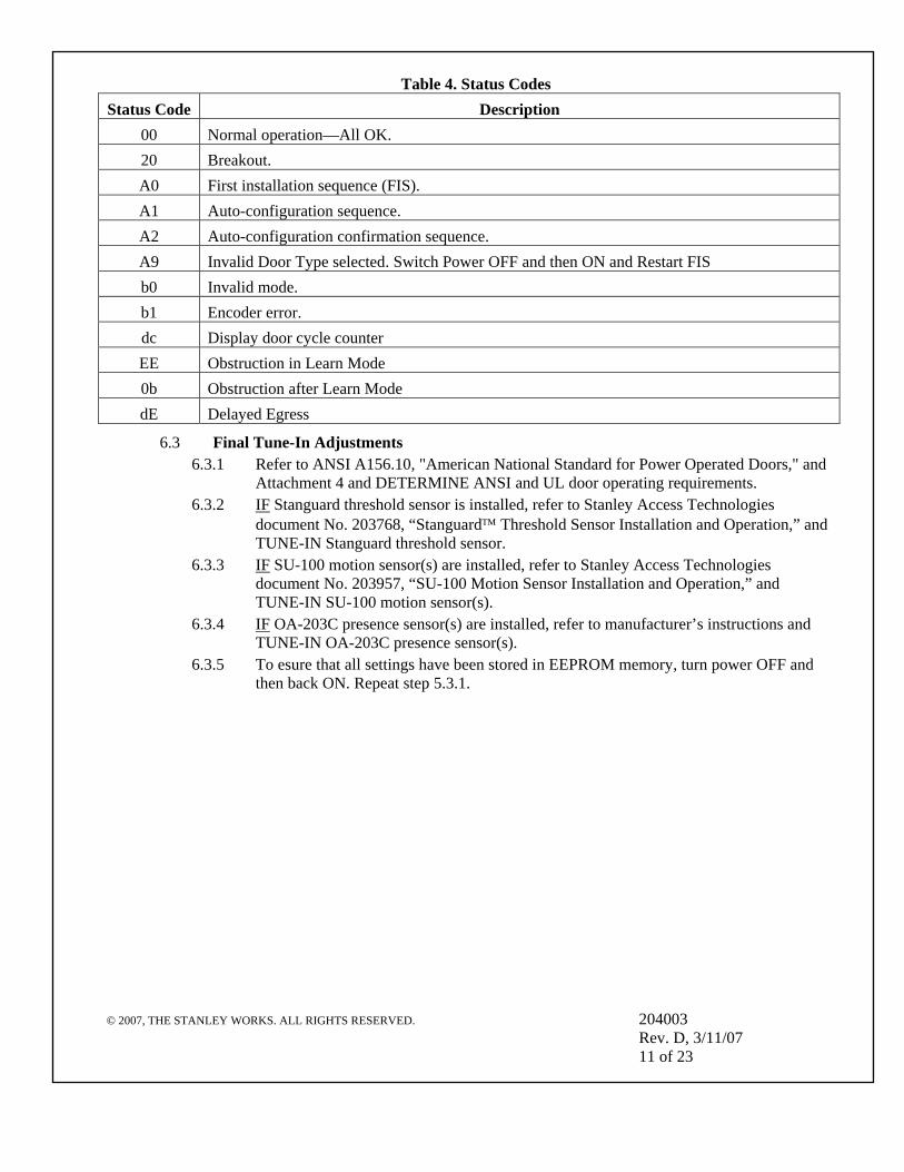
Table 4. Status Codes Status Code Description
00 Normal operation—All OK. 20 Breakout. A0 First installation sequence (FIS). A1 Auto-configuration sequence. A2 Auto-configuration confirmation sequence. A9 Invalid Door Type selected. Switch Power OFF and then ON and Restart FIS b0 Invalid mode. b1 Encoder error. dc Display door cycle counter EE Obstruction in Learn Mode 0b Obstruction after Learn Mode dE Delayed Egress
6.3 Final Tune-In Adjustments 6.3.1 Refer to ANSI A156.10, "American National Standard for Power Operated Doors," and
Attachment 4 and DETERMINE ANSI and UL door operating requirements. 6.3.2 IF Stanguard threshold sensor is installed, refer to Stanley Access Technologies
document No. 203768, “Stanguard™ Threshold Sensor Installation and Operation,” and TUNE-IN Stanguard threshold sensor.
6.3.3 IF SU-100 motion sensor(s) are installed, refer to Stanley Access Technologies document No. 203957, “SU-100 Motion Sensor Installation and Operation,” and TUNE-IN SU-100 motion sensor(s).
6.3.4 IF OA-203C presence sensor(s) are installed, refer to manufacturer’s instructions and TUNE-IN OA-203C presence sensor(s).
6.3.5 To esure that all settings have been stored in EEPROM memory, turn power OFF and then back ON. Repeat step 5.3.1.
© 2007, THE STANLEY WORKS. ALL RIGHTS RESERVED. 204003 Rev. D, 3/11/07 12 of 23
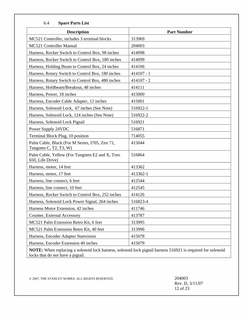
6.4 Spare Parts List
Description Part Number MC521 Controller, includes 3 terminal blocks 313969 MC521 Controller Manual 204003 Harness, Rocker Switch to Control Box, 98 inches 414098 Harness, Rocker Switch to Control Box, 180 inches 414099 Harness, Holding Beam to Control Box, 24 inches 414106 Harness, Rotary Switch to Control Box, 180 inches 414107 - 1 Harness, Rotary Switch to Control Box, 480 inches 414107 - 2 Harness, Holdbeam/Breakout, 48 inches 414111 Harness, Power, 18 inches 415000 Harness, Encoder Cable Adapter, 12 inches 415001 Harness, Solenoid Lock, 67 inches (See Note) 516922-1 Harness, Solenoid Lock, 124 inches (See Note) 516922-2 Harness, Solenoid Lock Pigtail 516921 Power Supply 24VDC 516871 Terminal Block Plug, 10 position 714055 Palm Cable, Black (For M Series, I705, Zire 71, Tungsten C, T2, T3, W)
415044
Palm Cable, Yellow (For Tungsten E2 and X, Treo 650, Life Drive)
516864
Harness, motor, 14 feet 413362 Harness, motor, 17 feet 413362-1 Harness, line connect, 6 feet 412544 Harness, line connect, 10 feet 412545 Harness, Rocker Switch to Control Box, 252 inches 414126 Harness, Solenoid Lock Power Signal, 264 inches 516823-4 Harness Motor Extension, 42 inches 411746 Counter, External Accessory 413787 MC521 Palm Extension Retro Kit, 6 feet 313995 MC521 Palm Extension Retro Kit, 40 feet 313996 Harness, Encoder Adapter Stanvision 415078 Harness, Encoder Extension 40 inches 415079 NOTE: When replacing a solenoid lock harness, solenoid lock pigtail harness 516921 is required for solenoid locks that do not have a pigtail.

204003 Rev. D, 3/11/07 Page 13 of 24 © 2007, THE STANLEY WORKS. ALL RIGHTS RESERVED.
Attachment 1 MC521 Controller Controls and Indicators
(Sheet 1 of 2)
J402
WARNING - FOR CONTINUED PROTECTION AGAINST FIRE,REPLACE ONLY WITH THE SAME TYPE AND RATING OF FUSE.
THIS OPERATOR CONTROL MUST BE ADJUSTED TO ANSISTANDARDS BY STANLEY TRAINED PERSONNEL.REFER TO INSTRUCTIONS FOR WIRING AND ADJUSTMENTS.
185000CONTROLLER
ACCESSTECHNOLOGIES
STANLEY
COM1
TB4
10
TB3
10
TB1
1
CO
M2
10 10
CO
M1
10
(RS
232)
DOWN
UP
TB4
TB2
10
S303
TB5
J403
ENCODER 1
S302
S301
ENTERTB3
10
12 VDC OUTPUT0.5A MAX
12 VAC OUTPUT1A MAX
TB5
10
ENCDR 1
U305ENCODER 2 U306
MOTOR 2
FUSE INSIDE.DISCONNECT POWERBEFORE SERVICING.
Z1101
MO
TOR
1
MOTOR 1J601
INPUT115V 50/60Hz
5A, 575W MAXR N
GL
J1101
MO
TOR
2
J901
J402
10
TB3
10
TB1
CO
M2
10 10
CO
M1
(RS
232)
DOWN
UP
TB4
TB2
10
S30
3
TB5
J403
ENCODER 1
S302
S301
ENTER
U305ENCODER 2 U306
DETAIL A
SEE DETAIL A
1
2
3
4
5 6
8
9
10
11
12
13
14
15
16
17
UC001A
7
1
10
1
10
INPUT 115V 50/60HZ
4A, 350W MAX
TB1 TB2
ENCDR 2
ENCDR 1
COM1
COM2

204003 Rev. D, 3/11/07 Page 14 of 24 © 2007, THE STANLEY WORKS. ALL RIGHTS RESERVED.
Attachment 1 MC521 Controller Controls and Indicators
(Sheet 2 of 2)
ITEM CONTROL/ INDICATOR
DESCRIPTION
1 Motor 2 Connector J109 Motor No. 2 connector. 2 Power Connector J1101 Connection point for incoming line, neutral, and common power wiring. 3 Fuse Z1101 Controller fuse-- 5 Amp, 250V 4 Motor 1 Connector J601 Motor No. 1 connector. 5 Terminal Block Connector
TB1 Connection point for door cycle counter and solenoid lock control.
6 Terminal Block Connector TB2
Connection point for function switch (rotary or rocker).
7 Encoder 2 Connector J403 Not Used 8 Two Digit Display Displays Controller Status. Also serves as the display for tune-in by pushbutton switches and indicates encoder
movement. 9 Encoder 1 Connector J402 Connection point for motor encoder No. 1.
10 Up Pushbutton Switch S302
Used manual setup and tuning of door when PDA is not available.
11 Down Pushbutton Switch S303
Used for manual setup and tuning of door when PDA is not available.
12 Enter Pushbutton Switch S301
Used for manual setup and tuning of door when PDA is not available.
13 COM1 Jack RS232 COM1 connector. Connection point for PDA harness. 14 COM2 Jack RS232 COM2 connector. Future provision. 15 Terminal Block Connector
TB5 Connection point for side-screen sensor and closed position switch.
16 Terminal Block Connector TB3
Connection point for Stanguard, doorway holding beam, and breakout switch. Using jumper wires across TB3 terminals 1 to 5 and 2 to 6, internal transformer supplies power to multiple external sensors.
17 Terminal Block Connector TB4
Connection point for inside sensor, outside sensor and push plate.
204003 Rev. D, 3/11/07 Page 15 of 24 © 2007, THE STANLEY WORKS. ALL RIGHTS RESERVED.
Attachment 2 MC521 System Wiring Diagram
(Sheet 1 of 4)
UC007_1C
TO SHEET 3

204003 Rev. D, 3/11/07 Page 16 of 24 © 2007, THE STANLEY WORKS. ALL RIGHTS RESERVED.
Attachment 2 MC521 System Wiring Diagram
(Sheet 2 of 4)
UC007_2A

204003 Rev. D, 3/11/07 Page 17 of 24 © 2007, THE STANLEY WORKS. ALL RIGHTS RESERVED.
Attachment 2 MC521 System Wiring Diagram
(Sheet 3 of 4)
TO SHEET 1
UC007_3D
516921
516922-1 OR 516922-2

204003 Rev. D, 3/11/07 Page 18 of 24 © 2007, THE STANLEY WORKS. ALL RIGHTS RESERVED.
Attachment 2 MC521 System Wiring Diagram
(Sheet 4 of 4)
UC007_4A
516921
516922-1 OR 516922-2
204003 Rev. D, 3/11/07 Page 19 of 24 © 2007, THE STANLEY WORKS. ALL RIGHTS RESERVED.
Attachment 3 MC521 Terminal Block Connections —TB1 through TB5
(Sheet 1 of 1
UC005G
9
10
8
6
7
5
3
4
2
1
9
10
8
6
7
5
3
4
2
1
9
10
8
6
7
5
3
4
2
1
9
10
8
6
7
5
3
4
2
1
TB3 TB5
ENTER - ONE WAY (BL)
REDUCED OPEN (VI)
HOLD OPEN POSITION (YL)
COMMON (OR)
AUTOMATIC POSITION (BN)
COMMON
COMMON (BL)
TB2(ROCKER SWITCH WIRING)
TB2(ROTARY SWITCH WIRING)
9
10
8
6
7
5
3
4
2
1
ENTER - ONE WAY (BN)
REDUCED OPEN (GN)
HOLD OPEN POSITION (BK)
COMMON (YL)
AUTOMATIC POSITION (RD)
COMMON (OR)
EXT
INT
EXT
INT
* REMOVE IF EXTERNAL POWER SUPPLY IS USED.
COMMON (WH)
OUTSIDE SENSOR (GN)
INSIDE SENSOR
PUSH PLATE
COMMON
12VAC (RD)
12VAC (BK)
12VAC (RD)
COMMON (WH)
COMMON (WH)
TB412VAC (BK)
12VAC (RD)
SIDE SCREEN SENSOR (GN)
12VAC (BK)
CLOSED POSITION SWITCH
COMMON (WH)
COMMON
12VAC
12VAC
STANGUARD (GN)
COMMON (WH)
HOLDING BEAM (GN)
BREAKOUT (GN)
12VAC (BK)
12VAC (RD)
12VAC (BK) *
12VAC (RD)*
COMMON (WH)
EXT
INT
SOLENOID LOCK (BL)
9
10
8
6
7
5
3
4
2
1
TB1
(RD)
CYCLE COUNTER(BK)
+ 24 VDC
24 VDC -
SOLENOID LOCK (BK) COMMON (VI)

204003 Rev. D, 3/11/07 Page 20 of 24 © 2007, THE STANLEY WORKS. ALL RIGHTS RESERVED.
Attachment 4 ANSI/BHMA and UL Compliance Requirements for Sliding Doors
(Sheet 1 of 2) Final adjustment and proper operation of the door system must be and shall be performed in the field. Note: These instructions are for informational purposes and do not substitute for review against the current revision of the referenced standards. Where a requirement exists in multiple standards, such as the ANSI/BHMA standard and the UL standard, the more restrictive condition applies. Other local codes and fire codes likely exist, and must also be followed. 1.0 ANSI/BHMA A156.10 Sliding Door Systems
Sliding door systems must be installed and adjusted for compliance with the current version of ANSI/BHMA A156.10, “American National Standard for Power Operated Pedestrian Doors”. Critical aspects of the installation for compliance with A156.10 include:
• Control mat size, layout, molding height, active areas and sensitivity. • Sensor pattern size, sensitivity, and function. • Knowing Act guidelines and secondary activating zone. • Entrapment protection rules including door speeds, forces, and time delays. • Signage. (Decals and application instructions are provided with the door system.)
2.0 UL 325 Compliance All power operated door systems must be installed in compliance with the current edition of UL 325, “Standard for Safety for Door, Drapery, Gate, Louver, and Window Operators and Systems”. 2.1 Wiring
2.1.1 To reduce the risk of electric shock proper and reliable grounding is mandatory. See Main Power Wiring instructions and Wiring Diagrams in this guide for grounding techniques.
2.1.2 Permanent wiring is to be employed as required by the National Electrical Code and/or local codes. 2.1.3 Connection of external devices is shown in the wiring diagrams and terminal block layouts elsewhere in this guide. Refer to
these figures for proper wiring of external devices to ensure compliance with UL 325. 2.2 Knowing Act
Doors activated by a manual switch (Knowing Act switch in ANSI/BHMA terms) must have the switch installed in a location from which operation of the door can be observed by the person operating the switch.

204003 Rev. D, 3/11/07 Page 21 of 24 © 2007, THE STANLEY WORKS. ALL RIGHTS RESERVED.
Attachment 4 ANSI/BHMA and UL Compliance Requirements for Sliding Doors
(Sheet 2 of 2)
2.3 To ensure that a sliding door operates in accordance with UL 325 entrapment protection criteria the following must be established: • Manual opening force (sliding doors without breakout) or breakout force with power on or off must be less then 50 lbf (222.4 N). • Closing force must be less than 30 lbf (133.4 N). • A closing sliding door must not develop kinetic energy in excess of 7 ft-lbf (9.49 J). This is achieved by proper setting of the closing speed. See section
entitled “Closing Speed”. • Maximum recommended door weight:
Dura-Glide 5000 Series = 150 lbs (70 kg) per panel. Dura-Glide/Dura-Guard/Dura-Storm and similar 2000/3000 Series = 220 lbs (100 kg) per panel. IS10000/Double Diamond and similar Industrial Series = 300 lbs (90 kg) per panel
2.4 Closing Speed
Closing speed is measured over a travel distance of 2 or 3 feet. On smaller bi-part doors there may only be 2 feet of movement before the door system enters close-check (latch check). The time measurement should start once the door has achieved closing speed, usually 6 inches from full open. Mark this point on the floor with tape or other object. Measure from this point 2 or 3 feet toward the closed position and mark the next point. Use a stopwatch to measure the time it takes for the sliding panel to travel this distance during normal closing cycles. Make sure the door system is not braking or entering close-check during the measurement. Repeat the measurement 3 times and use the average value. The allowed time for a sliding panel to cover this distance during the closing cycle is given in the table below.
Door Weight
(pounds) Closing speed (seconds)
2 foot measurement Closing time (seconds)
3 foot measurement 160 or less 2.0 3.0 161 to 180 2.1 3.2 181 to 200 2.2 3.3 201 to 220 2.3 3.5 221 to 240 2.4 3.7 241 to 260 2.5 3.8 261 to 280 2.6 4.0 281 to 300 2.7 4.1

204003 Rev. D, 3/11/07 Page 22 of 24 © 2007, THE STANLEY WORKS. ALL RIGHTS RESERVED.
Attachment 5 Palm Troubleshooting Aid
(Sheet 1 of 2
Terminal
& Pin Description State
TB1-5 External Cycle Counter Output Dark = low (counter increments) TB1-8 Solenoid Lock Output Dark = unlocked w/o PCB, fail secure Dark = unlocked w/o PCB, fail safe Dark = locked
Rotary Function Switch States for TB2
Hold Open
Closed/ Locked
Automatic Oneway Reduced Reduced/ Oneway
TB2-1
TB2-3
TB2-5 Don’t care Don’t care
TB2-7
Rocker Function Switch States for TB2
Hold Open
Closed/ Locked
Automatic Oneway Reduced Reduced/ Oneway
TB2-1
TB2-3
TB2-5 Don’t care
Don’t care
TB2-7 Don’t care
Don’t care

204003 Rev. D, 3/11/07 Page 23 of 24 © 2007, THE STANLEY WORKS. ALL RIGHTS RESERVED.
Attachment 5 Palm Troubleshooting Aid
(Sheet 2 of 2
Terminal & Pin
Description State
TB3-4 Stanguard Input/Output Dark = triggered or detecting TB3-8 & TB4-8
Holding Beam Input & Outside Sensor (connected internally)
Dark = detecting
TB3-9 Breakout Input Dark = no breakout TB4-4 & TB4-9
Inside Sensor Input & Push Plate Input (connected internally)
Dark = detecting
TB4-8 & TB3-8
Outside Sensor & Holding Beam Input (connected internally)
Dark = detecting
TB4-9 & TB4-4
Push Plate Input & Inside Sensor Input (connected internally)
Dark = detecting
TB5-3 Side Screen Sensor Input Dark = detecting TB5-7 Closed-Door Position Switch Input Dark = closed TB5-10 Spare
204003 Rev. D, 3/11/07 Page 24 of 24 © 2007, THE STANLEY WORKS. ALL RIGHTS RESERVED.
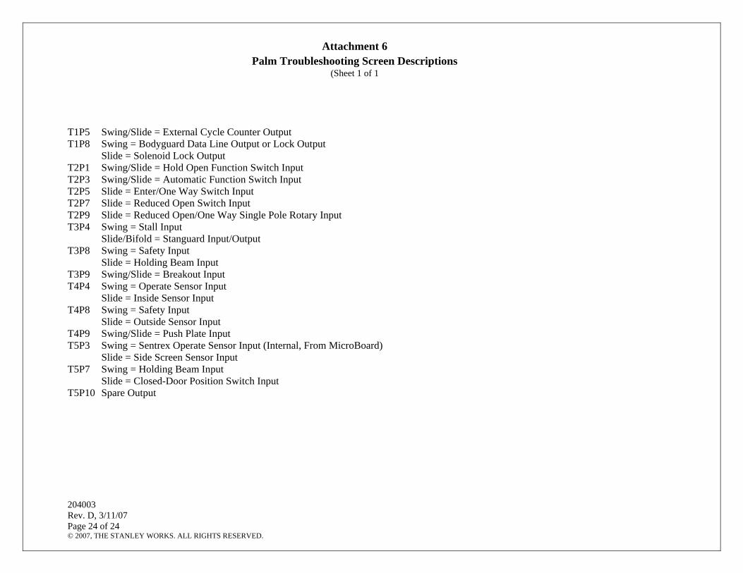
Attachment 6 Palm Troubleshooting Screen Descriptions
(Sheet 1 of 1
T1P5 Swing/Slide = External Cycle Counter Output T1P8 Swing = Bodyguard Data Line Output or Lock Output
Slide = Solenoid Lock Output T2P1 Swing/Slide = Hold Open Function Switch Input T2P3 Swing/Slide = Automatic Function Switch Input T2P5 Slide = Enter/One Way Switch Input T2P7 Slide = Reduced Open Switch Input T2P9 Slide = Reduced Open/One Way Single Pole Rotary Input T3P4 Swing = Stall Input
Slide/Bifold = Stanguard Input/Output T3P8 Swing = Safety Input
Slide = Holding Beam Input T3P9 Swing/Slide = Breakout Input T4P4 Swing = Operate Sensor Input
Slide = Inside Sensor Input T4P8 Swing = Safety Input
Slide = Outside Sensor Input T4P9 Swing/Slide = Push Plate Input T5P3 Swing = Sentrex Operate Sensor Input (Internal, From MicroBoard)
Slide = Side Screen Sensor Input T5P7 Swing = Holding Beam Input
Slide = Closed-Door Position Switch Input T5P10 Spare Output


![ZZ - fiqhulhadith.com ki kunjyan.pdf69 ----- *****™™*™™ÒÃÃÃÅÅÅÃÅääää™™™™]]]!!!!***hZZZå 71 -----*****™™™*™ÀÀÀÀÂÂÂÂ6666,,,vvvvZZZ{{{Z{ŠŠŠŠcc**c](https://img.dokumen.tips/doc/110x75/5e5e26f29bdb1829b545ee7d/zz-ki-kunjyanpdf-69-aaaaffffaaaahzzz.jpg)


![Rainbow Heart - artecy.com · 7777777 777777777 7777777777777 ooooooo 77777 7777777 7777777777777 oooooo]]]]] ddd ddd ddd ddd ddd ™™™™™™™™™™™ ™™™™™™™™™™™™™™™™™](https://img.dokumen.tips/doc/110x75/5f4a4ec8ec2fea16bc048a6a/rainbow-heart-7777777-777777777-7777777777777-ooooooo-77777-7777777-7777777777777.jpg)