Embed Size (px)
Citation preview

P/N: 1802012004014
*1802012004014*
MC-1200 Series Quick Installation Guide
Version 3.1, January 2021
Technical Support Contact Information www.moxa.com/support
2021 Moxa Inc. All rights reserved.

- 2 -
Overview The MC-1200 Series computers are built around a 7th Gen Intel® Celeron® or Intel® Core™ i3, i5, or i7 CPU and come with 1 HDMI display port, 3 USB 3.0 ports, 2 gigabit LAN ports, and 2 3-in-1 RS-232/422/485 serial ports. The MC-1200 is equipped with a 2.5” HDD/SSD slot and a built-in TPM 2.0 module. Additional value and convenience is provided through a modular design with three independent slots for flexible system integration and expansion. Users have the option to add a variety of different communications modules, including Wi-Fi, 3G, LTE, GPS, and mSATA expansion modules. The MC-1200 is designed to operate reliably in extreme conditions, such as continuous exposure to low or high temperatures, humidity, high vibration, and power surges, making them perfect for heavy industry, solar grid, water/wastewater, oil and gas, and transportation applications.
Package Checklist Before installing the MC-1200, verify that the package contains the following items:
• MC-1200 embedded computer • Terminal block to power jack converter • DIN-rail mounting kit • Quick installation guide (printed) • Warranty card
Please notify your sales representative if any of the above items are missing or damaged.
Panel Layout The panel layouts of the MC-1200 are shown in the following illustrations:
Front View

- 3 -
Top View Bottom View
LED Indicators
The following table describes the function of the LED indicators located on the front panel of the MC-1200:
LED Name Status Description Power
Green Power is on and computer is functioning normally
Off Power is off
Storage 1 (mSATA)
Yellow Blinking: Data transmission
Off No data transmission.
LAN 1/2 (on connectors)
Green Steady On: 100 Mbps Ethernet link Blinking: Data is being transmitted
Yellow Steady On: 1000 Mbps Ethernet link Blinking: Data is being transmitted
Off 10 Mbps Ethernet link or LAN is not connected
Tx 1/2 Green Blinking: Data is being transmitted.
Off No connection
Rx 1/2 Yellow Blinking: Data is being transmitted.
Off No connection

- 4 -
Installing the MC-1200 DIN-rail Mounting The MC-1200 comes with a DIN-rail mounting kit. To install the DIN-rail mounting kit, do the following:
STEP 1: Use the 4 screws included with the kit to attach the DIN-rail mounting bracket to the MC-1200’s rear panel and tighten the screws to secure the bracket to the MC-1200.
STEP 2: Insert the top of the DIN rail into the slot just below the upper hook of the DIN-rail mounting kit.
STEP 3: Press the MC-1200 towards the DIN rail until it snaps into place.
Removal:
STEP 1: Pull down the latch on the mounting kit with a screwdriver.
STEP 2 & 3: Slightly pull the MC-1200 forward and lift it up to remove it from the DIN rail.
For the specifications of the DIN-rail mounting screws, refer to the illustration on the right and adhere to these values to secure the DIN-rail bracket to the rear panel of the computer.

- 5 -
Wall Mounting The MC-1200 can be installed on a wall by using the optional wall-mounting kit. The wall-mounting kit must be purchased separately. STEP 1: Use three screws for each bracket and attach the brackets to the rear of the MC-1200.
Refer to the figure on the right for the specifications of the screws used to attach the mounting brackets.
STEP 2: Use two screws per bracket to attach the MC-1200 to a wall or cabinet. Note: Mounting the MC-1200 to a wall requires four screws. Use the MC-1200 computer, with the optional wall-mounting brackets attached, as a guide to mark the correct locations of the screws on the wall. The heads of the screws should be less than 6.0 mm in diameter, and the shafts should be less than 3.5 mm in diameter as shown in the figure on the right. Do not drive the screws in all the way; leave a space of about 2 mm to allow room for sliding the wall-mounting bracket between the wall and the screws.

- 6 -
Connector Description
Power Connector
Use an LPS (9-36 VDC) or Class 2 power cord to connect to the MC-1200's terminal block to power jack converter and then turn on the power. If the power is supplied properly, the Power LED will light up. The OS is ready when the Power LED glows a solid green.
ATTENTION
This product is intended to be supplied by a Listed Power Supply with output marked LPS and rated to deliver 9 to 36 VDC at a minimum of 8 A.
Grounding the MC-1200 Grounding and wire routing help limit the effects of noise due to electromagnetic interference (EMI). Run the ground connection from the grounding screw (M4) to the grounding surface prior to connecting the power as shown in the illustration on the right.
NOTE A 4 mm2 conductor must be used when the connection to the external grounding screw is utilized. The heat sink is grounded to the chassis by an internal screw.
Terminal Block Terminal block (JP1)—R/C (XCFR2, XCFR8), socket soldered on to the PWB, DINKLE ENTERPRISE CO., LTD, type 2EHDRM, rated 300 V, 15 A, 105°C. Mating with plug type 2RSDAM, 2ESDPM, 2ESDPLM or 2ESDVM, rated 300 V, 15 A, 105°C. The plug-half connection is secured by screws; suitable for 12 to 24 AWG wire size, secured on plug by screws with a torque value of 0.5 N-m (4.4253 lb-in).

- 7 -
Ethernet Ports The 10/100/1000 Mbps Ethernet ports use RJ45 connectors.
Pin 10/100 Mbps 1000 Mbps 1 ETx+ TRD(0)+ 2 ETx- TRD(0)- 3 ERx+ TRD(1)+ 4 – TRD(2)+ 5 – TRD(2)- 6 ERx- TRD(1)- 7 – TRD(3)+ 8 – TRD(3)-
Serial Ports The serial ports use DB9 connectors. Each port can be configured by software as a RS-232, RS-422, or RS-485 port. The pin assignments for the ports are shown below:
Pin RS-232 RS-422 RS-485 (4-wire)
RS-485 (2-wire)
1 DCD TxDA(-) TxDA(-) – 2 RxD TxDB(+) TxDB(+) – 3 TxD RxDB(+) RxDB(+) DataB(+) 4 DTR RxDA(-) RxDA(-) DataA(-) 5 GND GND GND GND 6 DSR – – – 7 RTS – – – 8 CTS – – –
USIM Slot The MC-1200 has two USIM slots for 3G/LTE wireless Internet connections. Each slot supports dual USIM cards. To install a USIM card, gently remove the outer cover on the bottom panel, and then insert the USIM card into the slot.
USB Hosts The MC-1200 has 3 USB 3.0 Type-A connectors located on the front panel. The ports support keyboard and mouse devices, and can also be used to connect a flash disk for storing large amounts of data.
HDMI Connector The MC-1200 has an HDMI connector located on the front panel, allowing users to connect to an audio or video device.
NOTE Make sure you use an HDIMI-certified cable for a reliable audio or video connection.

- 8 -
Installing Communications Modules
The MC-1200 Series comes with three sockets for installing various communications modules. Unfasten the screws on the right side of the computer and remove the cover to find the locations of these sockets as shown below:
Installing the mSATA Module
Insert the mSATA module into the socket and tighter the two screws on the mSATA module to secure it.

- 9 -
Installing the Wi-Fi Module
The MC-1200 comes with two sockets for users to install up to two Wi-Fi/cellular modules for wireless communication.
Wi-Fi Module Package The contents of the Wi-Fi module package are shown below:
Follow these steps to install the Wi-Fi module in the MC-1200.
1. Attach the Wi-Fi module to the mounting plate with two screws.
2. Remove the transparent
plastic and the blue cover on both sides of the thermal pad and then place it on the top heat sink. Also, remove the blue cover on the heat sink.
- 10 -
3. Place the heat sink with the thermal pad at the center of the wireless module socket.
4. Insert the Wi-Fi module (with
the mounting plate) into the socket and fasten the two black screws on the mounting plate to secure it.
5. Attach one end of the Wi-Fi
antenna cable to the connector on the Wi-Fi module and the insert the other end (with the threaded connection ring) through the antenna mounting hole on the front panel of the computer. Remove the protection cover on the mounting hole before you do so.
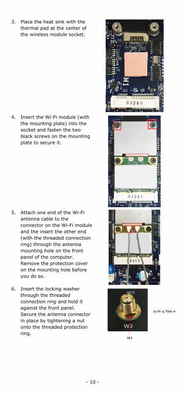
6. Insert the locking washer
through the threaded connection ring and hold it against the front panel. Secure the antenna connector in place by tightening a nut onto the threaded protection ring.

- 11 -
7. Connect the Wi-Fi antenna to the connector on the front panel.
8. Use this method to connect another Wi-Fi antenna, if necessary.
9. Reattach the right side cover on to the computer and fasten the screws to secure it.
Installing the Cellular Module
The MC-1200 comes with two sockets for users to install up to two Wi-Fi/cellular modules for wireless communication.
Cellular Module Package The contents of the Wi-Fi module package are shown below:
Follow these steps to install the cellular module in the MC-1220.
1. Remove the transparent plastic and the blue covers on both sides of the thermal pad and then place it on top of the heat sink. Also, remove the blue cover on the heat sink.

- 12 -
2. Place the heat sink with the thermal pad at the center of the cellular module socket.
3. Insert the cellular module
in the socket and fasten the two black screws on the module to secure it.
4. There are three
connectors on the cellular module: a GPS antenna connector and two cellular antenna connectors.
5. Attach one end of the
cellular antenna cable to a connector on the cellular module and the insert the other end (with the threaded connection ring) through the antenna mounting hole on the front panel of the computer. Remove the protection cover on the mounting hole before you do so.

- 13 -
6. Insert the locking washer through the threaded connection ring and hold it against the front panel. Secure the antenna connector in place by tightening a nut onto the threaded protection ring.
7. Connect the cellular
antenna to the connector provided on the front panel.
8. Use this method to connect another cellular antenna and the GPS antenna, if necessary.
9. Reattach the right side cover on to the computer and fasten the screws to secure it.
Installing SIM Cards Follow these steps to install SIM cards for a cellular module.
1. Remove the screws on the bottom panel of the computer and remove the cover. You will see four SIM card slots.
2. Insert a card into the SIM
1 slot. Make sure you insert the card in the right direction as indicated in the image beside the slot.
3. Insert the other card into the SIM 2 slot, if necessary.
4. Replace the computer cover and secure it by fastening the screws.

- 14 -
Switching Between the Wireless Module Socket
As there are two wireless module sockets and you can install the Wi-Fi or the cellular module in either of the sockets, a DIP switch is provided to enable selection of the Wi-Fi or cellular module installed. The DIP switch is located below the mSATA socket as shown in the following illustration.
The DIP switch operation is explained below:
Status Switch 1 Switch 2 ON Wi-Fi Wi-Fi
OFF (default) Cellular Cellular
For example, if you have installed a Wi-Fi module in the first socket, you need to turn the DIP switch 1 to the ON status.

- 15 -
ATEX and IECEx Details
Models MC-1220-KLX-T-YYYY (X = 0-9; Y = A-Z, 0-9, dash or blank, if without Y, dash can be blank) (for marketing purpose only and no impact safety related constructions and critical components)
Rating 9 to 36 VDC, 8 A ATEX Information
II 3 G DEMKO 20 ATEX 2386X Ex nA nC T4 Gc Ambient Range: -40°C ≤ Tamb ≤ +70°C Rated Cable Temp.≥ 130°C
IECEx Certificate No.
IECEx UL 20.0069X
ATTENTION
This equipment shall only be used in an area of not more than pollution degree 2, as defined in IEC/EN 60664-1.
This equipment shall be installed in an enclosure that provides a degree of protection not less than IP 54 in accordance with IEC/EN 60079-0 and accessibility only the use of a tool.
ATTENTION
This equipment is an open-type equipment that needs to be installed in an enclosure only accessible with the use of a tool suitable for the environment.
NOTE This equipment is suitable for use in Class I, Division 2, Groups A, B, C, and D or non-hazardous locations only.