Embed Size (px)
Citation preview

____________________MONOGRAM AEROSPACE FASTENERS 3423 South Garfield Avenue
Los Angeles, California 90040 Ph (323) 722-4760 * Fax (323) 721-1851
www.monogramaerospace.com
MBF2003
INSTALLATION & INSPECTION SPECIFICATION
FOR
COMPOSI-LOK® II
BLIND FASTENERS
(Authorizing signatures on file / printed copies for reference only)
REVISION: DATE: ECN# APPROVED BY: DATE:
NR 01-10-1984 ECN#3717
"AA" 01-06-1988 ECN#5217 _______________________________ ________
"AB" 02-22-1988 ECN#5353 JAMES C. EASTWOOD
"AC" 03-23-1988 ECN#5404 VICE PRESIDENT
"AD" 05-20-1988 ECN#5471 ENGINEERING/OPERATIONS
"AE" 07-10-2002 ECN#1379
“AF” 06-09-2006 ECN#3762 _______________________________ ________
“AG” 04-17-2008 ECN#4512 H. ROSS WAMBOLT
DIRECTOR, QUALITY ASSURANCE
_______________________________ ________
JOE LEE
DIRECTOR OF ENGINEERING
_____________________________ ________
PAULA MARTIN
METHODS MANAGER

____________________MONOGRAM AEROSPACE FASTENERS 3423 South Garfield Avenue
Los Angeles, California 90040 Ph (323) 722-4760 * Fax (323) 721-1851
www.monogramaerospace.com
TABLE OF CONTENTS
SECTION PAGE 1.0 SCOPE 3 2.0 DESCRIPTION 3 3.0 EQUIPMENT 3 4.0 GENERAL INFORMATION 3 5.0 DETAIL REQUIREMENTS 14 6.0 SELECTION OF GRIP LENGTH 16 7.0 DRIVING PROCEDURE 17 8.0 REMOVAL OF COMPOSI-LOK® II 18 9.0 SHAVING OF COMPOSI-LOK® II SCREWS (COREBOLTS) 18 10.0 INSPECTION AFTER INSTALLATION 19
TABLES 1 MP550BF PNEUMATIC PISTOL 4 2 MRT550BF PNEUMATIC RIGHT ANGLE TORQUE RESPONSIVE TOOL 5 3 MRC550 CLOSE QUARTER POWER TOOL 6 4 MRCR250 CLOSE QUARTER RATCHET TOOL 7 5 MR550 PNEUMATIC RIGHT ANGLE TOOL 8 6 MH75 HAND TOOL 9 7 MHC75 HAND TOOL CLOSE QUARTER 10 8 FASTENER CLOSE QUARTER TOOLING CLEARANCE 11 9 FASTENER REMOVAL KIT 12
10A TYPICAL MECHANICAL PROPERTIES 13 10B BLIND SIDE PROTRUSION 13 11 FASTENER HOLE PREPARATION & INSTALLED DIMENSIONS 15 12 SEATING TORQUE 19 13 MONOGRAM GAGES 20 FIGURES 1 MP550 BF PNEUMATIC PISTOL 4 2 MRT550 BF PNEUMATIC RIGHT ANGLE TORQUE RESPONSIVE TOOL 5 3 MRC550 CLOSE QUARTER POWER TOOL 6 4 MRCR250 CLOSE QUARTER RATCHET TOOL 7 5 MR550 PNEUMATIC RIGHT ANGLE TOOL 8 6 MH75 HAND TOOL 9 7 MHC75 HAND TOOL CLOSE QUARTER 10 8 FASTENER CLOSE QUARTER TOOLING CLEARANCE 11 9 FASTENER REMOVAL 12 10 BLIND SIDE PROTRUSION 13 11 FASTENER HOLE PREPARATION & INSTALLED DIMENSIONS 15 12 GRIP GAUGE 16 13 TAPERED SHEET CONDITION 16 14 FLUSH HEAD HEIGHT 17 15 DESCRIPTION OF INSTALLATION 18 16 MONOGRAM GAGES 20
MONOGRAM AEROSPACE FASTENERS
TITLE SPECIFICATION INSTALLATION AND INSPECTION SPECIFICATION MBF2003 FOR COMPOSI-LOKII PAGE 3 OF 20
REVISION: "AG" BLIND FASTENERS DATE: 04-17-08
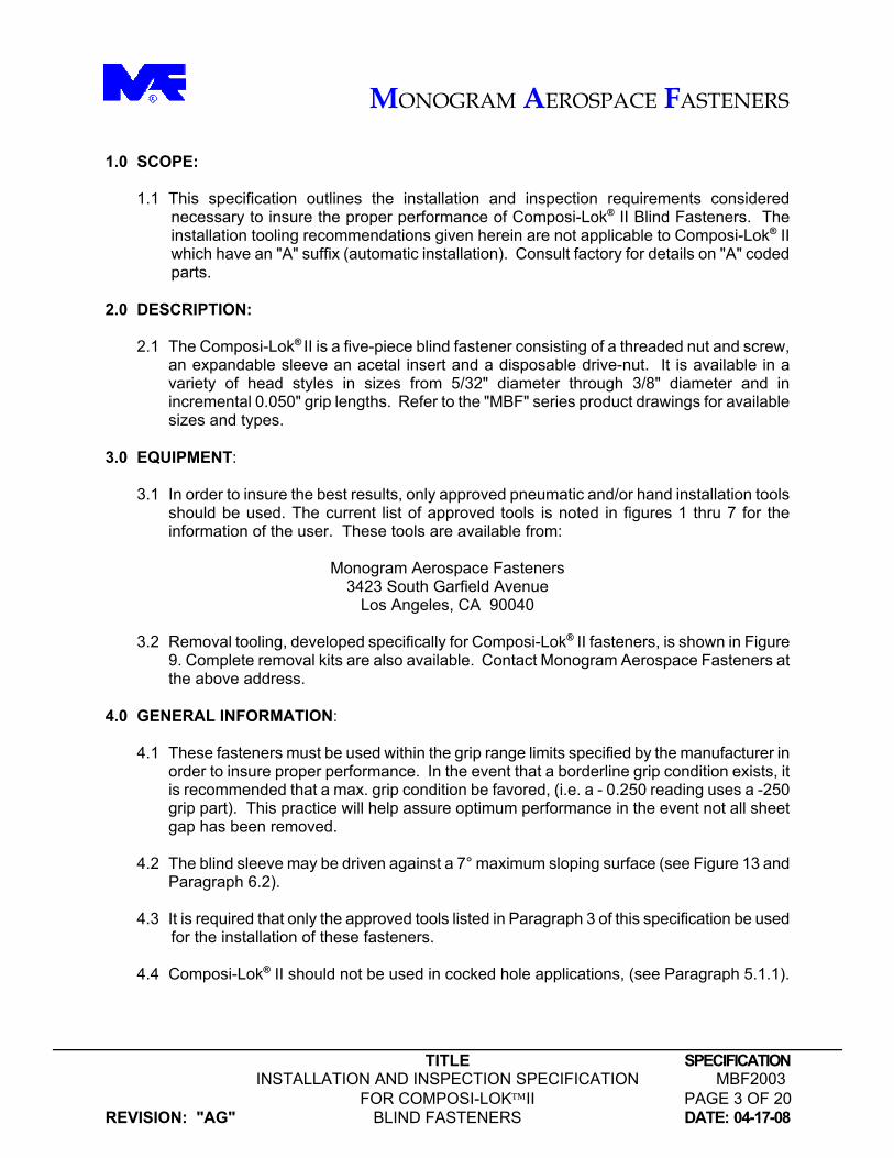
1.0 SCOPE:
1.1 This specification outlines the installation and inspection requirements considered necessary to insure the proper performance of Composi-Lok® II Blind Fasteners. The installation tooling recommendations given herein are not applicable to Composi-Lok® II which have an "A" suffix (automatic installation). Consult factory for details on "A" coded parts.
2.0 DESCRIPTION:
2.1 The Composi-Lok® II is a five-piece blind fastener consisting of a threaded nut and screw, an expandable sleeve an acetal insert and a disposable drive-nut. It is available in a variety of head styles in sizes from 5/32" diameter through 3/8" diameter and in incremental 0.050" grip lengths. Refer to the "MBF" series product drawings for available sizes and types.
3.0 EQUIPMENT:
3.1 In order to insure the best results, only approved pneumatic and/or hand installation tools should be used. The current list of approved tools is noted in figures 1 thru 7 for the information of the user. These tools are available from:
Monogram Aerospace Fasteners
3423 South Garfield Avenue Los Angeles, CA 90040
3.2 Removal tooling, developed specifically for Composi-Lok® II fasteners, is shown in Figure
9. Complete removal kits are also available. Contact Monogram Aerospace Fasteners at the above address.
4.0 GENERAL INFORMATION:
4.1 These fasteners must be used within the grip range limits specified by the manufacturer in order to insure proper performance. In the event that a borderline grip condition exists, it is recommended that a max. grip condition be favored, (i.e. a - 0.250 reading uses a -250 grip part). This practice will help assure optimum performance in the event not all sheet gap has been removed.
4.2 The blind sleeve may be driven against a 7° maximum sloping surface (see Figure 13 and
Paragraph 6.2).
4.3 It is required that only the approved tools listed in Paragraph 3 of this specification be used for the installation of these fasteners.
4.4 Composi-Lok® II should not be used in cocked hole applications, (see Paragraph 5.1.1).
MONOGRAM AEROSPACE FASTENERS
TITLE SPECIFICATION INSTALLATION AND INSPECTION SPECIFICATION MBF2003 FOR COMPOSI-LOKII PAGE 4 OF 20
REVISION: "AG" BLIND FASTENERS DATE: 04-17-08
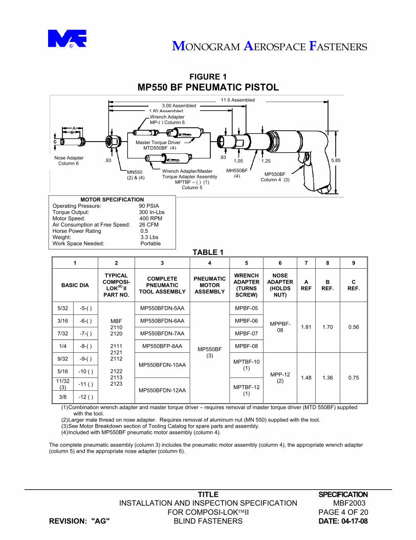
FIGURE 1
MP550 BF PNEUMATIC PISTOL
TABLE 1 1 2 3 4 5 6 7 8 9
BASIC DIA
TYPICAL COMPOSI-
LOK(R) II PART NO.
COMPLETE PNEUMATIC
TOOL ASSEMBLY
PNEUMATIC MOTOR
ASSEMBLY
WRENCH ADAPTER (TURNS SCREW)
NOSE ADAPTER (HOLDS
NUT)
A REF
B REF.
C REF.
5/32 -5-( ) MP550BFDN-5AA MPBF-05
3/16 -6-( ) MP550BFDN-6AA MPBF-06
7/32 -7-( ) MP550BFDN-7AA MPBF-07
1/4 -8-( ) MP550BFP-8AA MPBF-08
MPPBF-08 1.81 1.70 0.56
9/32 -9-( )
5/16 -10 ( ) MP550BFDN-10AA MPTBF-10
(1)
11/32 (3) -11 ( )
3/8 -12 ( )
MBF 2110 2120
2111 2121 2112
2122 2113 2123
MP550BFDN-12AA
MP550BF (3)
MPTBF-12 (1)
MPP-12 (2) 1.48 1.36 0.75
(1) Combination wrench adapter and master torque driver – requires removal of master torque driver (MTD 550BF) supplied with the tool.
(2) Larger male thread on nose adapter. Requires removal of aluminum nut (MN 550) supplied with the tool. (3) See Motor Breakdown section of Tooling Catalog for spare parts and assembly. (4) Included with MP550BF pneumatic motor assembly (column 4).
The complete pneumatic assembly (column 3) includes the pneumatic motor assembly (column 4), the appropriate wrench adapter (column 5) and the appropriate nose adapter (column 6).
11.5 Assembled 3.00 Assembled 1.80 AssembledWrench Adapter MP-( ) Column 6
Master Torque Driver MTD550BF (4)
Wrench Adapter/Master Torque Adapter Assembly
MPTBF – ( ) (1) Column 5
Nose Adapter Column 6
.93
MH550BF(4) MP550BF
Column 4 (3)
1.05 5.85 .93 1.25
MN550 (2) & (4)
MOTOR SPECIFICATION Operating Pressure: 90 PSIA Torque Output: 300 In-Lbs Motor Speed: 400 RPM Air Consumption at Free Speed: 26 CFM Horse Power Rating 0.5 Weight: 3.3 Lbs Work Space Needed: Portable
MONOGRAM AEROSPACE FASTENERS
TITLE SPECIFICATION INSTALLATION AND INSPECTION SPECIFICATION MBF2003 FOR COMPOSI-LOKII PAGE 5 OF 20
REVISION: "AG" BLIND FASTENERS DATE: 04-17-08
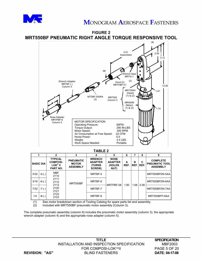
FIGURE 2 MRT550BF PNEUMATIC RIGHT ANGLE TORQUE RESPONSIVE TOOL
TABLE 2 1 2 3 4 5 6 7 8 9
BASIC DIA
TYPICAL COMPOSI-
LOK® II PART NO.
PNEUMATIC MOTOR
ASSEMBLY
WRENCH ADAPTER (TURNS SCREW)
NOSE ADAPTER (HOLDS
NUT)
A REF.
B REF.
C REF.
COMPLETE PNEUMATIC TOOL
ASSEMBLY
5/32 -5-( ) MRTBF-5 MRT550BFDN-5AA
3/16 -6-( ) MRTBF-6 MRT550BFDN-6AA
7/32 -7-( ) MRTBF-7 MRT550BFDN-7AA
1/4 -8-( )
MBF 2110 2111 2112 2113 2120 2121 2122 2123
MRT550BF
MRTBF-8
MRTPBF-08 1.80 1.68 0.56
MRT550BFP-8AA
(1) See motor breakdown section of Tooling Catalog for spare parts list and assembly. (2) Included with MRT550BF pneumatic motor assembly (Column 3).
The complete pneumatic assembly (column 9) includes the pneumatic motor assembly (column 3), the appropriate wrench adapter (column 4) and the appropriate nose adapter (column 5).
MOTOR SPECIFICATION Operating Pressure: 90PSI Torque Output: 290 IN-LBS Motor Speed: 400 RPM Air Consumption at Free Speed: 22 CFM Horse Power: 0.5 Weight: 3.4 LBS Work Space Needed: Portable
12.00
1.47
1.74
2.00
.38
3.12
2.61 Assembled
Wrench Gear MRTG-1
Hood (2) MRTHBF-01
.88
MRT550 Column 3
MRT550H(Head)
(1) & (2)
MR550M(Motor) (1) & (2)
MTDBF-550RA(2)
Wrench Adapter MRTBF-( ) Column 4
Nose Adapter MRTPBF-8 Column 5
(2)
MONOGRAM AEROSPACE FASTENERS
TITLE SPECIFICATION INSTALLATION AND INSPECTION SPECIFICATION MBF2003 FOR COMPOSI-LOKII PAGE 6 OF 20
REVISION: "AG" BLIND FASTENERS DATE: 04-17-08
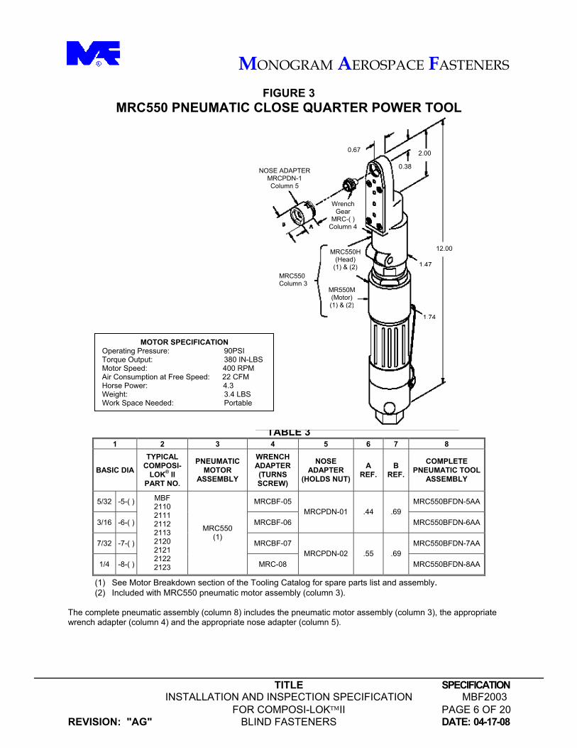
FIGURE 3 MRC550 PNEUMATIC CLOSE QUARTER POWER TOOL
TABLE 3 1 2 3 4 5 6 7 8
BASIC DIA
TYPICAL COMPOSI-
LOK® II PART NO.
PNEUMATIC MOTOR
ASSEMBLY
WRENCH ADAPTER (TURNS SCREW)
NOSE ADAPTER
(HOLDS NUT)
A REF.
B REF.
COMPLETE PNEUMATIC TOOL
ASSEMBLY
5/32 -5-( ) MRCBF-05 MRC550BFDN-5AA
3/16 -6-( ) MRCBF-06 MRCPDN-01 .44 .69
MRC550BFDN-6AA
7/32 -7-( ) MRCBF-07 MRC550BFDN-7AA
1/4 -8-( )
MBF 2110 2111 2112 2113 2120 2121 2122 2123
MRC550 (1)
MRC-08 MRCPDN-02 .55 .69
MRC550BFDN-8AA
(1) See Motor Breakdown section of the Tooling Catalog for spare parts list and assembly. (2) Included with MRC550 pneumatic motor assembly (column 3).
The complete pneumatic assembly (column 8) includes the pneumatic motor assembly (column 3), the appropriate wrench adapter (column 4) and the appropriate nose adapter (column 5).
12.00
0.38
1.47
2.00
1.74
0.67
MRC550 Column 3
MRC550H(Head)
(1) & (2)
MR550M(Motor) (1) & (2)
Wrench Gear
MRC-( ) Column 4
NOSE ADAPTER MRCPDN-1 Column 5
MOTOR SPECIFICATION Operating Pressure: 90PSI Torque Output: 380 IN-LBS Motor Speed: 400 RPM Air Consumption at Free Speed: 22 CFM Horse Power: 4.3 Weight: 3.4 LBS Work Space Needed: Portable
MONOGRAM AEROSPACE FASTENERS
TITLE SPECIFICATION INSTALLATION AND INSPECTION SPECIFICATION MBF2003 FOR COMPOSI-LOKII PAGE 7 OF 20
REVISION: "AG" BLIND FASTENERS DATE: 04-17-08
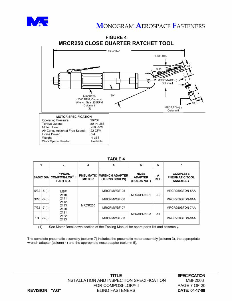
FIGURE 4 MRCR250 CLOSE QUARTER RATCHET TOOL
TABLE 4 1 2 3 4 5 6 7
BASIC DIA TYPICAL
COMPOSI-LOK® II PART NO.
PNEUMATIC MOTOR
WRENCH ADAPTER (TURNS SCREW)
NOSE ADAPTER
(HOLDS NUT)
A REF.
COMPLETE PNEUMATIC TOOL
ASSEMBLY
5/32 -5-( ) MRCRMWBF-05 MRCR250BFDN-5AA
3/16 -6-( ) MRCRMWBF-06 MRCRPDN-01 .69
MRCR250BFDN-6AA
7/32 -7-( ) MRCRMWBF-07 MRCR250BFDN-7AA
1/4 -8-( )
MBF 2110 2111 2112 2113 2120 2121 2122 2123
MRCR250
MRCRMWBF-08 MRCRPDN-02 .81
MRCR250BFDN-8AA
(1) See Motor Breakdown section of the Tooling Manual for spare parts list and assembly.
The complete pneumatic assembly (column 7) includes the pneumatic motor assembly (column 3), the appropriate wrench adapter (column 4) and the appropriate nose adapter (column 5).
MOTOR SPECIFICATION Operating Pressure: 90PSI Torque Output: 80 IN-LBS Motor Speed: 250 RPM Air Consumption at Free Speed: 22 CFM Horse Power: 3.4 Weight: 4 LBS Work Space Needed: Portable
.36
13 ½” Ref.
2 3/8” Ref.
20° MRCR250 (2000 RPM, Output at Wrench Gear 250RPM
Column 3 (1)
MRCRMWBF-( ) Column 4
.69 MRCRPDN-( )
Column 5
.38
3.33
MONOGRAM AEROSPACE FASTENERS
TITLE SPECIFICATION INSTALLATION AND INSPECTION SPECIFICATION MBF2003 FOR COMPOSI-LOKII PAGE 8 OF 20
REVISION: "AG" BLIND FASTENERS DATE: 04-17-08
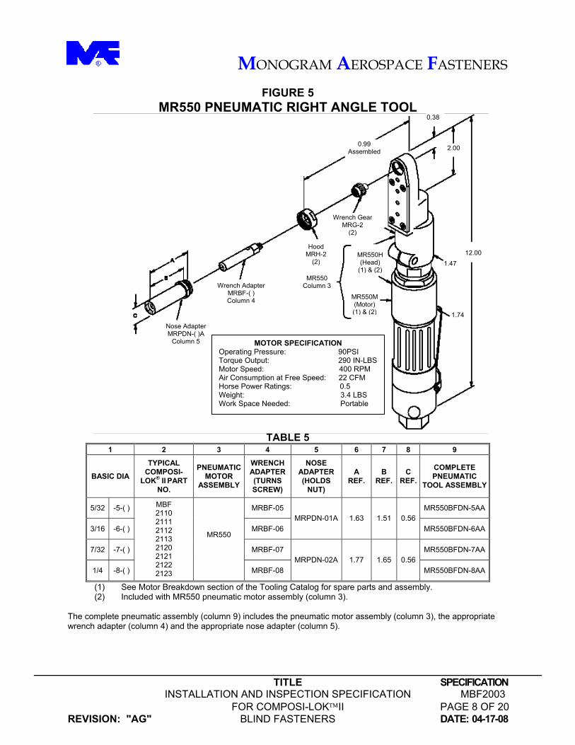
FIGURE 5 MR550 PNEUMATIC RIGHT ANGLE TOOL
TABLE 5 1 2 3 4 5 6 7 8 9
BASIC DIA
TYPICAL COMPOSI-
LOK® II PART NO.
PNEUMATICMOTOR
ASSEMBLY
WRENCH ADAPTER (TURNS SCREW)
NOSE ADAPTER (HOLDS
NUT)
A REF.
B REF.
C REF.
COMPLETE PNEUMATIC
TOOL ASSEMBLY
5/32 -5-( ) MRBF-05 MR550BFDN-5AA
3/16 -6-( ) MRBF-06 MRPDN-01A 1.63 1.51 0.56
MR550BFDN-6AA
7/32 -7-( ) MRBF-07 MR550BFDN-7AA
1/4 -8-( )
MBF 2110 2111 2112 2113 2120 2121 2122 2123
MR550
MRBF-08 MRPDN-02A 1.77 1.65 0.56
MR550BFDN-8AA
(1) See Motor Breakdown section of the Tooling Catalog for spare parts and assembly. (2) Included with MR550 pneumatic motor assembly (column 3). The complete pneumatic assembly (column 9) includes the pneumatic motor assembly (column 3), the appropriate wrench adapter (column 4) and the appropriate nose adapter (column 5).
1.74
Wrench AdapterMRBF-( ) Column 4
MR550 Column 3
MR550M(Motor) (1) & (2)
MR550H(Head)
(1) & (2)
0.99 Assembled
Wrench GearMRG-2
(2)
12.00
2.00
0.38
1.47
Nose Adapter MRPDN-( )A
Column 5
Hood MRH-2
(2)
MOTOR SPECIFICATION Operating Pressure: 90PSI Torque Output: 290 IN-LBS Motor Speed: 400 RPM Air Consumption at Free Speed: 22 CFM Horse Power Ratings: 0.5 Weight: 3.4 LBS Work Space Needed: Portable
MONOGRAM AEROSPACE FASTENERS
TITLE SPECIFICATION INSTALLATION AND INSPECTION SPECIFICATION MBF2003 FOR COMPOSI-LOKII PAGE 9 OF 20
REVISION: "AG" BLIND FASTENERS DATE: 04-17-08
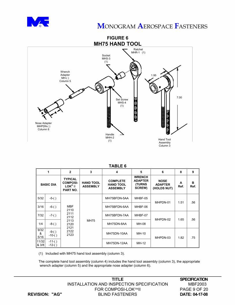
FIGURE 6 MH75 HAND TOOL
TABLE 6 1 2 3 4 5 6 8 9
BASIC DIA
TYPICAL COMPOSI-
LOK® II
PART NO.
HAND TOOL ASSEMBLY
COMPLETE HAND TOOL ASSEMBLY
WRENCH ADAPTER (TURNS SCREW)
NOSE ADAPTER
(HOLDS NUT)
A Ref.
B Ref.
5/32 -5-( ) MH75BFDN-5AA MHBF-05
3/16 -6-( ) MH75BFDN-6AA MHBF-06 MHPDN-01 1.51 .56
7/32 -7-( ) MH75BFDN-7AA MHBF-07
1/4 -8-( ) MH75DN-8AA MH-08 MHPDN-02 1.65 .56
9/32 &
5/16
-9-( ) -10-( ) MH75DN-10AA MH-10
11/32 & 3/8
-11-( ) -12-( )
MBF 2110 2111 2112 2113 2120 2121 2122 2123
MH75
MH75DN-12AA MH-12
MHPDN-03 1.82 .75
(1) Included with MH75 hand tool assembly (column 3).
The complete hand tool assembly (column 4) includes the hand tool assembly (column 3), the appropriate
wrench adapter (column 5) and the appropriate nose adapter (column 6).
Nose Adapter MHPDN-( ) Column 6
Wrench Adapter MH-( )
Column 5
Socket MHS-3
(1)
Ratchet MHR-1 (1)
Handle MHH-2
(1)
Set Screw MHS-4
(1)
7.00
Hand Tool Assembly Column 3
1.95
MONOGRAM AEROSPACE FASTENERS
TITLE SPECIFICATION INSTALLATION AND INSPECTION SPECIFICATION MBF2003 FOR COMPOSI-LOKII PAGE 10 OF 20
REVISION: "AG" BLIND FASTENERS DATE: 04-17-08
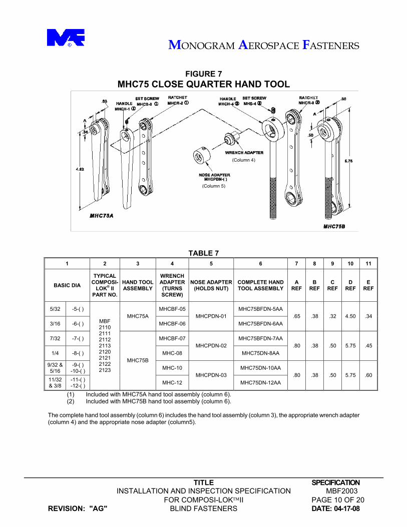
FIGURE 7
MHC75 CLOSE QUARTER HAND TOOL
TABLE 7 1 2 3 4 5 6 7 8 9 10 11
BASIC DIA
TYPICAL COMPOSI-
LOK® II PART NO.
HAND TOOL ASSEMBLY
WRENCH ADAPTER (TURNS SCREW)
NOSE ADAPTER (HOLDS NUT)
COMPLETE HAND TOOL ASSEMBLY
A REF
B REF
C REF
D REF
E REF
5/32 -5-( ) MHCBF-05 MHC75BFDN-5AA
3/16 -6-( ) MHC75A
MHCBF-06 MHCPDN-01
MHC75BFDN-6AA .65 .38 .32 4.50 .34
7/32 -7-( ) MHCBF-07 MHC75BFDN-7AA
1/4 -8-( ) MHC-08 MHCPDN-02
MHC75DN-8AA .80 .38 .50 5.75 .45
9/32 & 5/16
-9-( ) -10-( ) MHC-10 MHC75DN-10AA
11/32 & 3/8
-11-( ) -12-( )
MBF 2110 2111 2112 2113 2120 2121 2122 2123
MHC75B
MHC-12 MHCPDN-03
MHC75DN-12AA .80 .38 .50 5.75 .60
(1) Included with MHC75A hand tool assembly (column 6). (2) Included with MHC75B hand tool assembly (column 6).
The complete hand tool assembly (column 6) includes the hand tool assembly (column 3), the appropriate wrench adapter (column 4) and the appropriate nose adapter (column5).
(Column 4)
(Column 5)
MONOGRAM AEROSPACE FASTENERS
TITLE SPECIFICATION INSTALLATION AND INSPECTION SPECIFICATION MBF2003 FOR COMPOSI-LOKII PAGE 11 OF 20
REVISION: "AG" BLIND FASTENERS DATE: 04-17-08
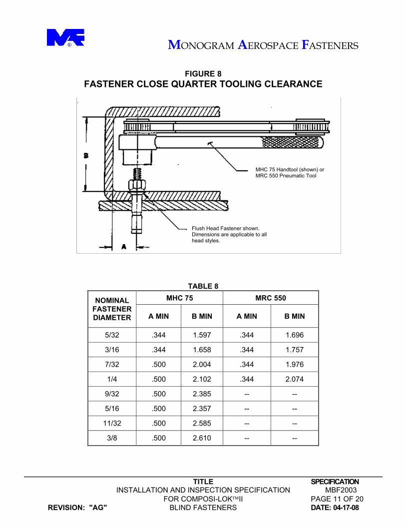
FIGURE 8
FASTENER CLOSE QUARTER TOOLING CLEARANCE
TABLE 8 MHC 75 MRC 550 NOMINAL
FASTENER DIAMETER A MIN B MIN A MIN B MIN
5/32 .344 1.597 .344 1.696
3/16 .344 1.658 .344 1.757
7/32 .500 2.004 .344 1.976
1/4 .500 2.102 .344 2.074
9/32 .500 2.385 -- --
5/16 .500 2.357 -- --
11/32 .500 2.585 -- --
3/8 .500 2.610 -- --
Flush Head Fastener shown. Dimensions are applicable to all head styles.
MHC 75 Handtool (shown) or MRC 550 Pneumatic Tool

MONOGRAM AEROSPACE FASTENERS
TITLE SPECIFICATION INSTALLATION AND INSPECTION SPECIFICATION MBF2003 FOR COMPOSI-LOKII PAGE 12 OF 20
REVISION: "AG" BLIND FASTENERS DATE: 04-17-08
FIGURE 9 FASTENER REMOVAL
TABLE 9 1 2 3 4 5 6
NOMINAL FASTENER DIAMETER
HEAD STYLE (5) NOSE PIECE
MODULE PART NO.
CARBIDE STAR DRILL
PART NO.
DRILL SIZE DIA. +.0000/.0005 DEPTH GAGE
FLUSH RM3118-05 -5 (.1635) PROTRUDING HEX RM3122-05 RM3116-05 .1540
FLUSH RM3118-06 -6 (.1975) PROTRUDING HEX RM3122-06 RM3116-06 .1890
FLUSH RM3118-07 -7 (.2265) (1) PROTRUDING HEX RM3122-07 RM3116-07 .2180
FLUSH RM3118-08 -8 (.2585) PROTRUDING HEX RM3122-08 RM3116-08 .2500
RM3125-01
FLUSH RM3118-09 -9 (.2885) (1) PROTRUDING HEX RM3122-09 RM3116-09 .2810
FLUSH RM3118-10 -10 (.3105) PROTRUDING HEX RM3122-10 RM3116-10 .3020
FLUSH RM3118-11 -11 (.3425) (1) PROTRUDING HEX RM3122-11 RM3116-11 .3320
FLUSH RM3118-12 -12 (.3735) PROTRUDING HEX RM3122-12 RM3116-12 .3590
RM3125-02
(1) Used on Composi-LokTM fasteners only. (2) Also available as vacuum index assisted RK5000 Removal kit for removal of -5, -6 and -8 diameter Visu-Loks® and
Composi-Loks®. Contact factory for removal of H-11 and Inconel Monogram fasteners. (3) Corebolt protrusion should be milled flush prior to removal. (4) A complete tool consists of the air motor module (RM3197), a nose piece module (column 3) and a carbide star drill
(column 4). A depth gage (column 6) is required for setting drilling depth. (5) Use flush head style nose piece modules for non-hexagonal protruding head fasteners (e.g. MBF2110 and MBF2120).
DRILL MOTOR ASSEMBLY
FLUSH HEAD NOSE PIECE PROTRUDING HEX HEAD NOSE PIECE
RM3197 AIR MOTOR MODULE
MONOGRAM AEROSPACE FASTENERS
TITLE SPECIFICATION INSTALLATION AND INSPECTION SPECIFICATION MBF2003 FOR COMPOSI-LOKII PAGE 13 OF 20
REVISION: "AG" BLIND FASTENERS DATE: 04-17-08
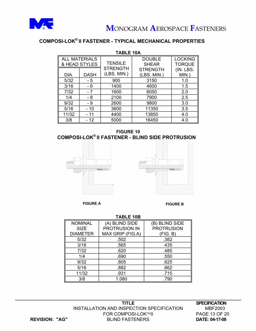
COMPOSI-LOK® II FASTENER - TYPICAL MECHANICAL PROPERTIES
TABLE 10A ALL MATERIALS & HEAD STYLES
DIA. DASH
TENSILE STRENGTH (LBS. MIN.)
DOUBLE SHEAR
STRENGTH (LBS. MIN.)
LOCKING TORQUE (IN. LBS.
MIN.) 5/32 - 5 900 3150 1.0 3/16 - 6 1400 4600 1.5 7/32 - 7 1600 6050 2.0 1/4 - 8 2100 7900 2.5
9/32 - 9 2600 9800 3.0 5/16 - 10 3600 11350 3.5
11/32 - 11 4400 13850 4.0 3/8 - 12 5000 16450 4.0
FIGURE 10
COMPOSI-LOK® II FASTENER - BLIND SIDE PROTRUSION TABLE 10B
NOMINAL SIZE
DIAMETER
(A) BLIND SIDE PROTRUSION IN MAX GRIP (FIG.A)
(B) BLIND SIDE PROTRUSION
(FIG. B) 5/32 .502 .382 3/16 .565 .435 7/32 .620 .485 1/4 .690 .550
9/32 .805 .625 5/16 .882 .662
11/32 .931 .715 3/8 1.080 .790
FIGURE A FIGURE B

MONOGRAM AEROSPACE FASTENERS
TITLE SPECIFICATION INSTALLATION AND INSPECTION SPECIFICATION MBF2003 FOR COMPOSI-LOKII PAGE 14 OF 20
REVISION: "AG" BLIND FASTENERS DATE: 04-17-08
4.5 Composi-Lok® II are supplied to the user with proper lubrication to insure satisfactory
driving characteristics. This lubricant should not be removed or any additional lubricant added.
4.6 If a fastener has been removed, the same diameter Composi-Lok® II can be reinstalled
provided the hole has not been damaged. In the event that the hole has been damaged, the next larger diameter Composi-Lok® II should be used (NOTE: for flush head fasteners the countersink will have to be deepened).
4.7 If the fastener is to be coated with primer prior to installation, extreme care should be
taken to insure that no primer will get on the thread of the screw in the sleeve area, under the head of the screw or on the sleeve and nose of the nut. Wet primer applied to these areas will act as a lubricant and tend to cause over-driving of the fastener. Dried-on primer may act as a retardant. When primer is required for additional corrosion protection, it is recommended that the primer be applied to the underside (bearing area) of the fastener head.
4.8 Use of the fastener in special applications necessitating the use of sealants, paints, etc.
should be thoroughly investigated by the user prior to installation. 5.0 DETAIL REQUIREMENTS.
5.1 Hole and Sheet Preparation.
5.1.1 Holes shall be drilled straight and perpendicular (within 1½°) to the surface against which the manufactured head will bear. The hole shall be reasonably round and free from burrs (metallic structure) and delamination (graphite/epoxy type structure).
The edge of fastener installation holes for both protruding and flush head style Composi-Lok® II should be given a slight chamfer on the head side as a radius relief to insure proper seating of the bearing surfaces. Chamfer should be equivalent in size to 50% of the maximum head to shank fillet radius specified on product drawings.
5.1.2 The sheets to be joined should be firmly clamped up or otherwise fixtured to prevent
hole misalignment.
5.1.3 The recommended hole sizes and countersink diameter for the various type Composi-Lok® II are shown in Table 11. The countersink diameters shown may be adjusted to suit a specific manufacturer's flushness requirements, as desired.
MONOGRAM AEROSPACE FASTENERS
TITLE SPECIFICATION INSTALLATION AND INSPECTION SPECIFICATION MBF2003 FOR COMPOSI-LOKII PAGE 15 OF 20
REVISION: "AG" BLIND FASTENERS DATE: 04-17-08
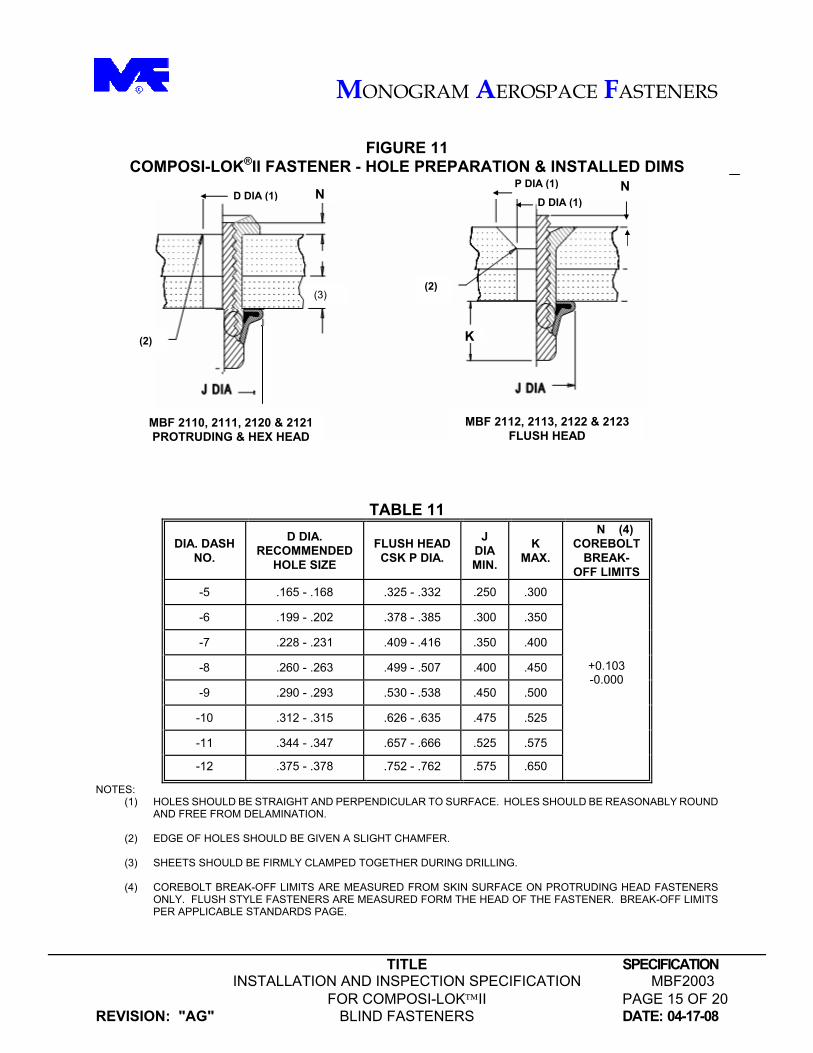
FIGURE 11 COMPOSI-LOK®II FASTENER - HOLE PREPARATION & INSTALLED DIMS
TABLE 11
DIA. DASH NO.
D DIA. RECOMMENDED
HOLE SIZE
FLUSH HEAD CSK P DIA.
J DIA MIN.
K MAX.
N (4) COREBOLT
BREAK-OFF LIMITS
-5 .165 - .168 .325 - .332 .250 .300
-6 .199 - .202 .378 - .385 .300 .350
-7 .228 - .231 .409 - .416 .350 .400
-8 .260 - .263 .499 - .507 .400 .450
-9 .290 - .293 .530 - .538 .450 .500
-10 .312 - .315 .626 - .635 .475 .525
-11 .344 - .347 .657 - .666 .525 .575
-12 .375 - .378 .752 - .762 .575 .650
+0.103 -0.000
NOTES: (1) HOLES SHOULD BE STRAIGHT AND PERPENDICULAR TO SURFACE. HOLES SHOULD BE REASONABLY ROUND
AND FREE FROM DELAMINATION.
(2) EDGE OF HOLES SHOULD BE GIVEN A SLIGHT CHAMFER.
(3) SHEETS SHOULD BE FIRMLY CLAMPED TOGETHER DURING DRILLING.
(4) COREBOLT BREAK-OFF LIMITS ARE MEASURED FROM SKIN SURFACE ON PROTRUDING HEAD FASTENERS ONLY. FLUSH STYLE FASTENERS ARE MEASURED FORM THE HEAD OF THE FASTENER. BREAK-OFF LIMITS PER APPLICABLE STANDARDS PAGE.
K
MBF 2110, 2111, 2120 & 2121 PROTRUDING & HEX HEAD
MBF 2112, 2113, 2122 & 2123 FLUSH HEAD
(2)
(2)
N N D DIA (1) P DIA (1)
D DIA (1)
(3)
MONOGRAM AEROSPACE FASTENERS
TITLE SPECIFICATION INSTALLATION AND INSPECTION SPECIFICATION MBF2003 FOR COMPOSI-LOKII PAGE 16 OF 20
REVISION: "AG" BLIND FASTENERS DATE: 04-17-08
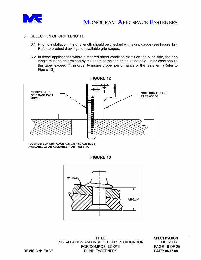
6. SELECTION OF GRIP LENGTH.
6.1 Prior to installation, the grip length should be checked with a grip gauge (see Figure 12). Refer to product drawings for available grip ranges.
6.2 In those applications where a tapered sheet condition exists on the blind side, the grip
length must be determined by the depth at the centerline of the hole. In no case should this taper exceed 7°, in order to insure proper performance of the fastener. (Refer to Figure 13).
FIGURE 12
FIGURE 13
*COMPOSI-LOK GRIP GAGE PART #BFS-1
*GRIP SCALE SLIDE PART #GSS-1
*COMPOSI-LOK GRIP GAGE AND GRIP SCALE SLIDE AVAILABLE AS AN ASSEMBLY - PART #BFS-1A
MONOGRAM AEROSPACE FASTENERS
TITLE SPECIFICATION INSTALLATION AND INSPECTION SPECIFICATION MBF2003 FOR COMPOSI-LOKII PAGE 17 OF 20
REVISION: "AG" BLIND FASTENERS DATE: 04-17-08
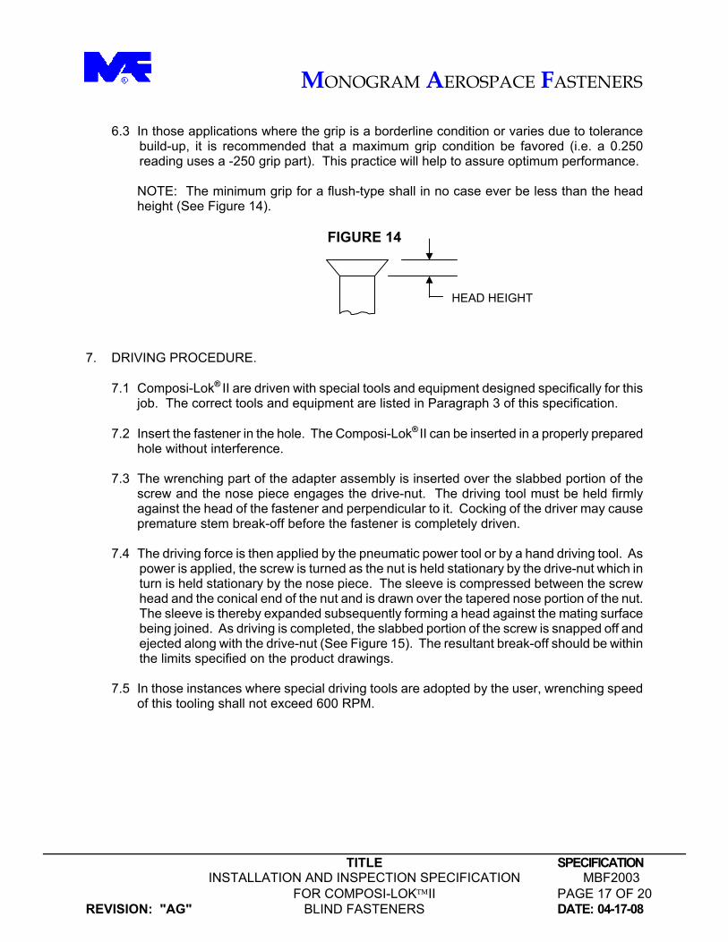
6.3 In those applications where the grip is a borderline condition or varies due to tolerance
build-up, it is recommended that a maximum grip condition be favored (i.e. a 0.250 reading uses a -250 grip part). This practice will help to assure optimum performance.
NOTE: The minimum grip for a flush-type shall in no case ever be less than the head height (See Figure 14).
FIGURE 14
7. DRIVING PROCEDURE.
7.1 Composi-Lok® II are driven with special tools and equipment designed specifically for this job. The correct tools and equipment are listed in Paragraph 3 of this specification.
7.2 Insert the fastener in the hole. The Composi-Lok® II can be inserted in a properly prepared
hole without interference.
7.3 The wrenching part of the adapter assembly is inserted over the slabbed portion of the screw and the nose piece engages the drive-nut. The driving tool must be held firmly against the head of the fastener and perpendicular to it. Cocking of the driver may cause premature stem break-off before the fastener is completely driven.
7.4 The driving force is then applied by the pneumatic power tool or by a hand driving tool. As
power is applied, the screw is turned as the nut is held stationary by the drive-nut which in turn is held stationary by the nose piece. The sleeve is compressed between the screw head and the conical end of the nut and is drawn over the tapered nose portion of the nut. The sleeve is thereby expanded subsequently forming a head against the mating surface being joined. As driving is completed, the slabbed portion of the screw is snapped off and ejected along with the drive-nut (See Figure 15). The resultant break-off should be within the limits specified on the product drawings.
7.5 In those instances where special driving tools are adopted by the user, wrenching speed
of this tooling shall not exceed 600 RPM.
HEAD HEIGHT

MONOGRAM AEROSPACE FASTENERS
TITLE SPECIFICATION INSTALLATION AND INSPECTION SPECIFICATION MBF2003 FOR COMPOSI-LOKII PAGE 18 OF 20
REVISION: "AG" BLIND FASTENERS DATE: 04-17-08
FIGURE 15
DESCRIPTION OF INSTALLATION
8. REMOVAL OF COMPOSI-LOK® II
8.1 Composi-Lok® II may be removed with the tooling shown in Figure 9 of this specification. Complete kits are available from Monogram Aerospace Fasteners. Contact factory for details.
9. SHAVING OF COMPOSI-LOK® II SCREWS (COREBOLTS)
9.1 The corebolt protrusion may be shaved flush with the sheet surface using a standard rivet shaver equipped with a carbide cutter. The shaver must turn at a speed of approximately 10,000 RPM. The cutter and skirt diameter must be large enough to permit the corebolt to be approximately 3/16" from the center of the cutter. The shaver will not mill properly if the corebolt is centered on the cutter. A one-inch diameter cutter will be required for most fasteners. Monogram’s Pintail Shaving unit has been developed to slice the corebolt, producing an uninterrupted cut. A supplement to MAF’s Pintail Shaving unit is the Miller, a very effective corebolt flushing tool. Contact factory for further details.
10. INSPECTION AFTER INSTALLATION. 10.1 The stem break-off position of the screw in the head of the nut is a positive indication that
the fastener has been properly installed (provided that the correct grip length has been used).
PINTAIL & DRIVE-NUT EJECTED
DRIVING TOOL IN PLACE
NUT
BLIND SLEEVE
DRIVE-NUT
Nose adapter of driving tool in place – must be held perpendicular to work and firm against drive-nut.
SCREW
MONOGRAM AEROSPACE FASTENERS
TITLE SPECIFICATION INSTALLATION AND INSPECTION SPECIFICATION MBF2003 FOR COMPOSI-LOKII PAGE 19 OF 20
REVISION: "AG" BLIND FASTENERS DATE: 04-17-08
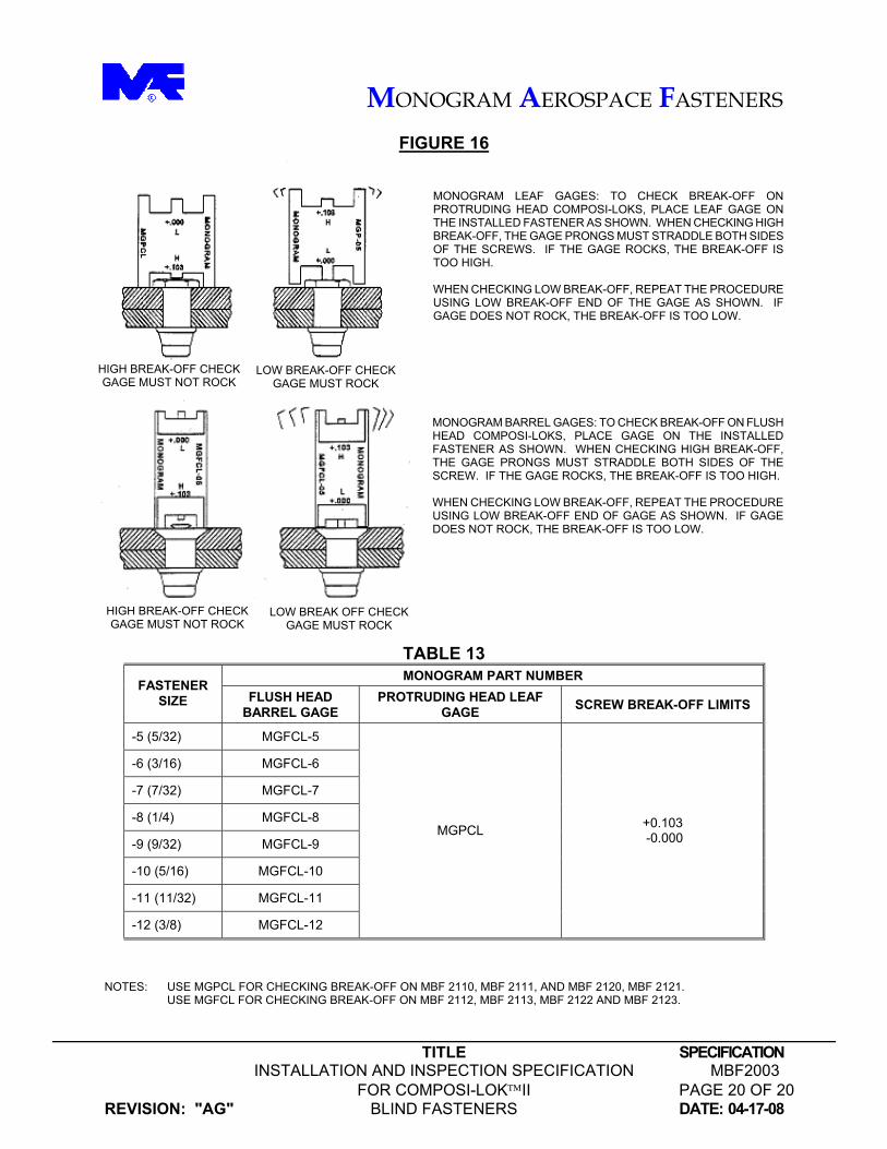
10.1 Continued: Product drawings list the acceptable stem break-off limits for a properly installed fastener. Stem break-off beyond acceptable tolerances as prescribed may indicate the use of the wrong grip fastener or other problem. In either case, the fastener should be removed, the grip length carefully check, and then replaced by the correct grip fastener, as necessary. Stem break-off gages are available for inspection of the installed fasteners. Refer to Figure 16.
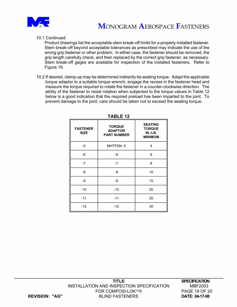
10.2 If desired, clamp-up may be determined indirectly be seating torque. Adapt the applicable torque adaptor to a suitable torque wrench, engage the recess in the fastener head and measure the torque required to rotate the fastener in a counter-clockwise direction. The ability of the fastener to resist rotation when subjected to the torque values in Table 12 below is a good indication that the required preload has been imparted to the joint. To prevent damage to the joint, care should be taken not to exceed the seating torque.
TABLE 12
FASTENER SIZE
TORQUE ADAPTOR
PART NUMBER
SEATING TORQUE IN.-LB.
MINIMUM
-5 MHTFDN -5 4
-6 -6 6
-7 -7 8
-8 -8 10
-9 -9 15
-10 -10 20
-11 -11 25
-12 -12 30
MONOGRAM AEROSPACE FASTENERS
TITLE SPECIFICATION INSTALLATION AND INSPECTION SPECIFICATION MBF2003 FOR COMPOSI-LOKII PAGE 20 OF 20
REVISION: "AG" BLIND FASTENERS DATE: 04-17-08
FIGURE 16 MONOGRAM LEAF GAGES: TO CHECK BREAK-OFF ON PROTRUDING HEAD COMPOSI-LOKS, PLACE LEAF GAGE ON THE INSTALLED FASTENER AS SHOWN. WHEN CHECKING HIGH BREAK-OFF, THE GAGE PRONGS MUST STRADDLE BOTH SIDES OF THE SCREWS. IF THE GAGE ROCKS, THE BREAK-OFF IS TOO HIGH. WHEN CHECKING LOW BREAK-OFF, REPEAT THE PROCEDURE USING LOW BREAK-OFF END OF THE GAGE AS SHOWN. IF GAGE DOES NOT ROCK, THE BREAK-OFF IS TOO LOW.
MONOGRAM BARREL GAGES: TO CHECK BREAK-OFF ON FLUSH HEAD COMPOSI-LOKS, PLACE GAGE ON THE INSTALLED FASTENER AS SHOWN. WHEN CHECKING HIGH BREAK-OFF, THE GAGE PRONGS MUST STRADDLE BOTH SIDES OF THE SCREW. IF THE GAGE ROCKS, THE BREAK-OFF IS TOO HIGH. WHEN CHECKING LOW BREAK-OFF, REPEAT THE PROCEDURE USING LOW BREAK-OFF END OF GAGE AS SHOWN. IF GAGE DOES NOT ROCK, THE BREAK-OFF IS TOO LOW.
TABLE 13 MONOGRAM PART NUMBER
FASTENER SIZE FLUSH HEAD
BARREL GAGE PROTRUDING HEAD LEAF
GAGE SCREW BREAK-OFF LIMITS
-5 (5/32) MGFCL-5
-6 (3/16) MGFCL-6
-7 (7/32) MGFCL-7
-8 (1/4) MGFCL-8
-9 (9/32) MGFCL-9
-10 (5/16) MGFCL-10
-11 (11/32) MGFCL-11
-12 (3/8) MGFCL-12
MGPCL +0.103 -0.000
NOTES: USE MGPCL FOR CHECKING BREAK-OFF ON MBF 2110, MBF 2111, AND MBF 2120, MBF 2121.
USE MGFCL FOR CHECKING BREAK-OFF ON MBF 2112, MBF 2113, MBF 2122 AND MBF 2123.
HIGH BREAK-OFF CHECK GAGE MUST NOT ROCK
LOW BREAK-OFF CHECKGAGE MUST ROCK
HIGH BREAK-OFF CHECK GAGE MUST NOT ROCK
LOW BREAK OFF CHECK GAGE MUST ROCK