Embed Size (px)
Citation preview

MB86298-EB01Ruby Evaluation Board
Documentation
Version: 3.1Date: 03/01/2010
GEMAC mbH · Zwickauer Strasse 227 · 09116 Chemnitz · GermanyTelephone: +49 371 3377 – 0 · Telefax: +49 371 3377 – 272
E-Mail: [email protected] · Web: www.gemac-chemnitz.de
MB86298-EB01 Ruby Evaluation Board Document Revisions
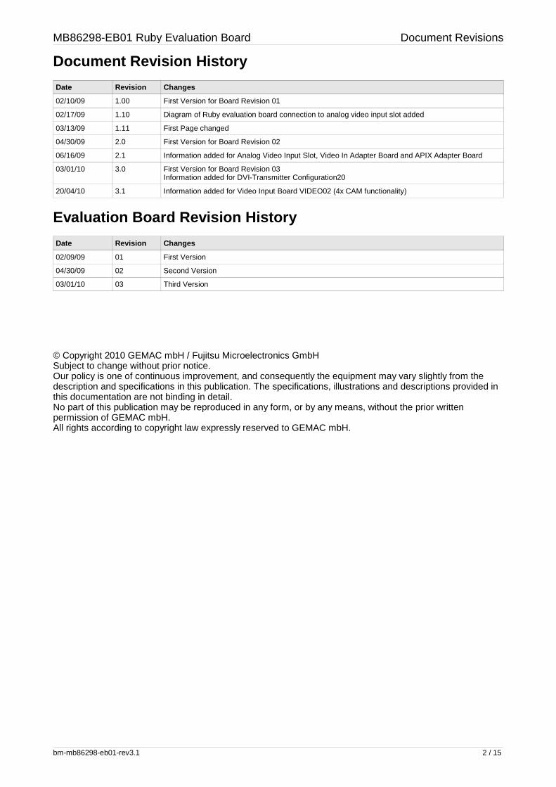
Document Revision History
Date Revision Changes
02/10/09 1.00 First Version for Board Revision 01
02/17/09 1.10 Diagram of Ruby evaluation board connection to analog video input slot added
03/13/09 1.11 First Page changed
04/30/09 2.0 First Version for Board Revision 02
06/16/09 2.1 Information added for Analog Video Input Slot, Video In Adapter Board and APIX Adapter Board
03/01/10 3.0 First Version for Board Revision 03Information added for DVI-Transmitter Configuration20
20/04/10 3.1 Information added for Video Input Board VIDEO02 (4x CAM functionality)
Evaluation Board Revision History
Date Revision Changes
02/09/09 01 First Version
04/30/09 02 Second Version
03/01/10 03 Third Version
© Copyright 2010 GEMAC mbH / Fujitsu Microelectronics GmbHSubject to change without prior notice.Our policy is one of continuous improvement, and consequently the equipment may vary slightly from thedescription and specifications in this publication. The specifications, illustrations and descriptions provided inthis documentation are not binding in detail.No part of this publication may be reproduced in any form, or by any means, without the prior writtenpermission of GEMAC mbH.All rights according to copyright law expressly reserved to GEMAC mbH.
bm-mb86298-eb01-rev3.1 2 / 15

MB86298-EB01 Ruby Evaluation Board Contents
Contents
1. Ruby Evaluation Board....................................................................................................................................51.1. Overview ....................................................................................................................................................51.2. Main Board External Appearance..............................................................................................................61.3. Test Points.................................................................................................................................................81.4. LEDs...........................................................................................................................................................81.5. DIP-Switches..............................................................................................................................................91.6. GPIO's......................................................................................................................................................101.7. Analog Video Input Slot............................................................................................................................11
1.7.1. Overview...............................................................................................................111.7.2. Connection to Ruby Evaluation Board..................................................................11
2. Adapter Boards..............................................................................................................................................122.1. Video In Adapter Board 01 (MB86298-VIDEO01)....................................................................................122.2. Video In Adapter Board 02 (MB86298-VIDEO02)....................................................................................132.3. APIX Adapter Board.................................................................................................................................14
bm-mb86298-eb01-rev3.1 3 / 15

MB86298-EB01 Ruby Evaluation Board Tables and Figures
Tables
Table 1: Description of Test Points on Ruby Evaluation Board ........................................ 8Table 2: Description of functionality of Ruby evaluation board LED's .............................. 8Table 3: Switch S1 settings on Ruby evaluation board .................................................... 9Table 4: Switch S3 settings on Ruby evaluation board .................................................... 9Table 5: Switch S4, S5, S6 settings on Ruby evaluation board ....................................... 9Table 6: Connector X1 on Ruby evaluation board ......................................................... 10Table 7: Switch S1 on Video In Adapter Board .............................................................. 13Table 8: Jumper J1 on APIX Adapter Board .................................................................. 15
Figures
Figure 1: Block Diagram.....................................................................................................5Figure 2: Interfaces and configurations on the Ruby Evaluation Board top side................6Figure 3: Test points and configurations on the Ruby Evaluation Board bottom side........7Figure 4: Interfaces on the analogue video input slot.......................................................11Figure 5: Connection between Ruby evaluation board and Analog Video Input Slot.......11Figure 6: Interfaces and configurations on the Video In Adapter Board 01.....................12Figure 7: Interfaces on the Video In Adapter Board 01 bottom side................................12Figure 8: Interfaces on the Video In Adapter Board 02....................................................13Figure 9: Interfaces on the Video In Adapter Board 02 bottom side................................14Figure 10: Interfaces and configurations on the APIX Adapter Board..............................14Figure 11: Interfaces on the APIX Adapter Board bottom side........................................15
bm-mb86298-eb01-rev3.1 4 / 15

MB86298-EB01 Ruby Evaluation Board
1. Ruby Evaluation Board
1.1. Overview
bm-mb86298-eb01-rev3.1 5 / 15
Figure 1: Block Diagram

1.2. Main Board External Appearance
Figure 2: Interfaces and configurations on the Ruby Evaluation Board top side
A B C
A B C
Compact DVI-I Connector (Dual-Link)
LED1 - Power-Fail 1.8VLED2 - Power-Fail 1.2VLED3 - Power-Fail 5.0V
Extension Board Input Connector
Extension Board Output Connector
Capture 2ITU656 / RGB666
Display Out 1(RGB888)
Display Out 0(RGB888)
Cature 3Input 1 (RGB666)
Cature 1(ITU656 / RGB666)
Second-SlotCable Connector
Capture AV-InputSelector
GPIO / I2C / SPIAuxiliary Signals GPIO-Leds
ClockmodeSwitch
Board ResetBottonReset-LED
SATA-Power Plug(optional)

Figure 3: Test points and configurations on the Ruby Evaluation Board bottom side
C B A
C B A
C B A
C B A
Display 0DVI-Transmitter Config Switch
Display 1DVI-Transmitter Config Switch
DVI-Transmitter EDGE-Configuration
Switch

MB86298-EB01 Ruby Evaluation Board
1.3. Test Points
The following table shows the assignment of the test points on bottom side of theevaluation board to their corresponding signals.
MP Signal MP Signal
1 1.8V (Ruby-Core-Voltage) 6 VTTDDR2 (DDR2-RAM Terminator Voltage)
2 5.0V 7 VREFDDR2 (DDR2-RAM Reference Voltage)
3 1.2V (Ruby-Core-Voltage) 11-17 Ground
4 3.3V (Board-I/O-Voltage)
5 3.3V (From PCI-Express)
Table 1: Description of Test Points on Ruby Evaluation Board
1.4. LEDs
The evaluation board contains various LED's on the top side to visualize different boardconditions. The following table contains a description of functionality of all on board LED's.
LED Function Color OK-Condition
Description
LD1 Power-Fail 1.8VCore Red Off LED is light up, if the DC-DC-Converter output produces no stable 1.8V.In OK condition the LED should be switched off.
LD2 Power-Fail 1.2VCore Red Off LED is light up, if the DC-DC-Converter output produces no stable 1.2V.In OK condition the LED should be switched off.
LD3 Power-Fail 5.0V Red Off LED is light up, if the DC-DC-Converter output produces no stable 5.0V.In OK condition the LED should be switched off.
LD5 MB86298-XRST-Reset Green On LED is light up, if XRST-Reset is released (OK condition).
LD6 GPIO0-Led Red - LED is light up, if GPIO0 is configured as output and programmed tohigh level.
LD7 GPIO2-Led Red - LED is light up, if GPIO2 is configured as output and programmed tohigh level.
LD8 GPIO1-Led Green - LED is light up, if GPIO1 is configured as output and programmed tohigh level.
LD9 GPIO3-Led Green - LED is light up, if GPIO3 is configured as output and programmed tohigh level.
Table 2: Description of functionality of Ruby evaluation board LED's
bm-mb86298-eb01-rev3.1 8 / 15
MB86298-EB01 Ruby Evaluation Board
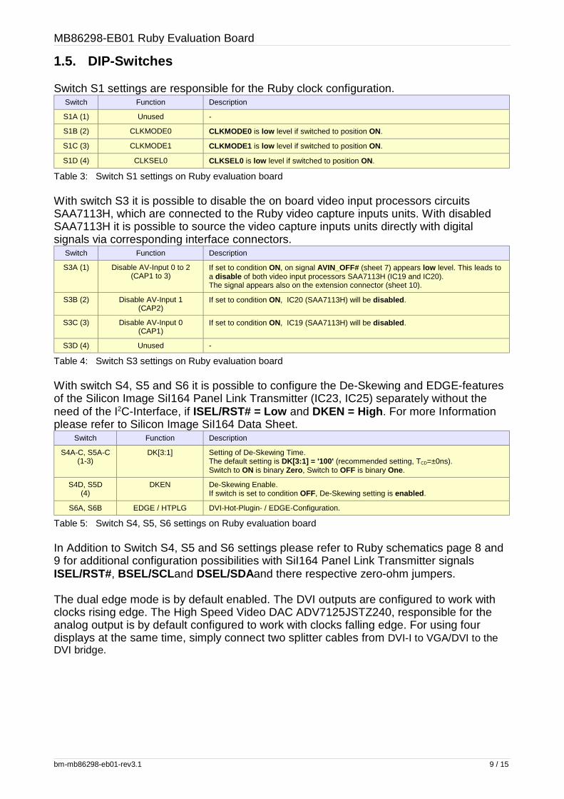
1.5. DIP-Switches
Switch S1 settings are responsible for the Ruby clock configuration.Switch Function Description
S1A (1) Unused -
S1B (2) CLKMODE0 CLKMODE0 is low level if switched to position ON.
S1C (3) CLKMODE1 CLKMODE1 is low level if switched to position ON.
S1D (4) CLKSEL0 CLKSEL0 is low level if switched to position ON.
Table 3: Switch S1 settings on Ruby evaluation board
With switch S3 it is possible to disable the on board video input processors circuitsSAA7113H, which are connected to the Ruby video capture inputs units. With disabledSAA7113H it is possible to source the video capture inputs units directly with digitalsignals via corresponding interface connectors.
Switch Function Description
S3A (1) Disable AV-Input 0 to 2(CAP1 to 3)
If set to condition ON, on signal AVIN_OFF# (sheet 7) appears low level. This leads toa disable of both video input processors SAA7113H (IC19 and IC20).The signal appears also on the extension connector (sheet 10).
S3B (2) Disable AV-Input 1(CAP2)
If set to condition ON, IC20 (SAA7113H) will be disabled .
S3C (3) Disable AV-Input 0(CAP1)
If set to condition ON, IC19 (SAA7113H) will be disabled .
S3D (4) Unused -
Table 4: Switch S3 settings on Ruby evaluation board
With switch S4, S5 and S6 it is possible to configure the De-Skewing and EDGE-featuresof the Silicon Image SiI164 Panel Link Transmitter (IC23, IC25) separately without theneed of the I2C-Interface, if ISEL/RST# = Low and DKEN = High . For more Informationplease refer to Silicon Image SiI164 Data Sheet.
Switch Function Description
S4A-C, S5A-C(1-3)
DK[3:1] Setting of De-Skewing Time.The default setting is DK[3:1] = '100' (recommended setting, TCD=±0ns).Switch to ON is binary Zero , Switch to OFF is binary One.
S4D, S5D(4)
DKEN De-Skewing Enable.If switch is set to condition OFF, De-Skewing setting is enabled .
S6A, S6B EDGE / HTPLG DVI-Hot-Plugin- / EDGE-Configuration.
Table 5: Switch S4, S5, S6 settings on Ruby evaluation board
In Addition to Switch S4, S5 and S6 settings please refer to Ruby schematics page 8 and9 for additional configuration possibilities with SiI164 Panel Link Transmitter signalsISEL/RST#, BSEL/SCL and DSEL/SDAand there respective zero-ohm jumpers.
The dual edge mode is by default enabled. The DVI outputs are configured to work withclocks rising edge. The High Speed Video DAC ADV7125JSTZ240, responsible for theanalog output is by default configured to work with clocks falling edge. For using fourdisplays at the same time, simply connect two splitter cables from DVI-I to VGA/DVI to theDVI bridge.
bm-mb86298-eb01-rev3.1 9 / 15
MB86298-EB01 Ruby Evaluation Board
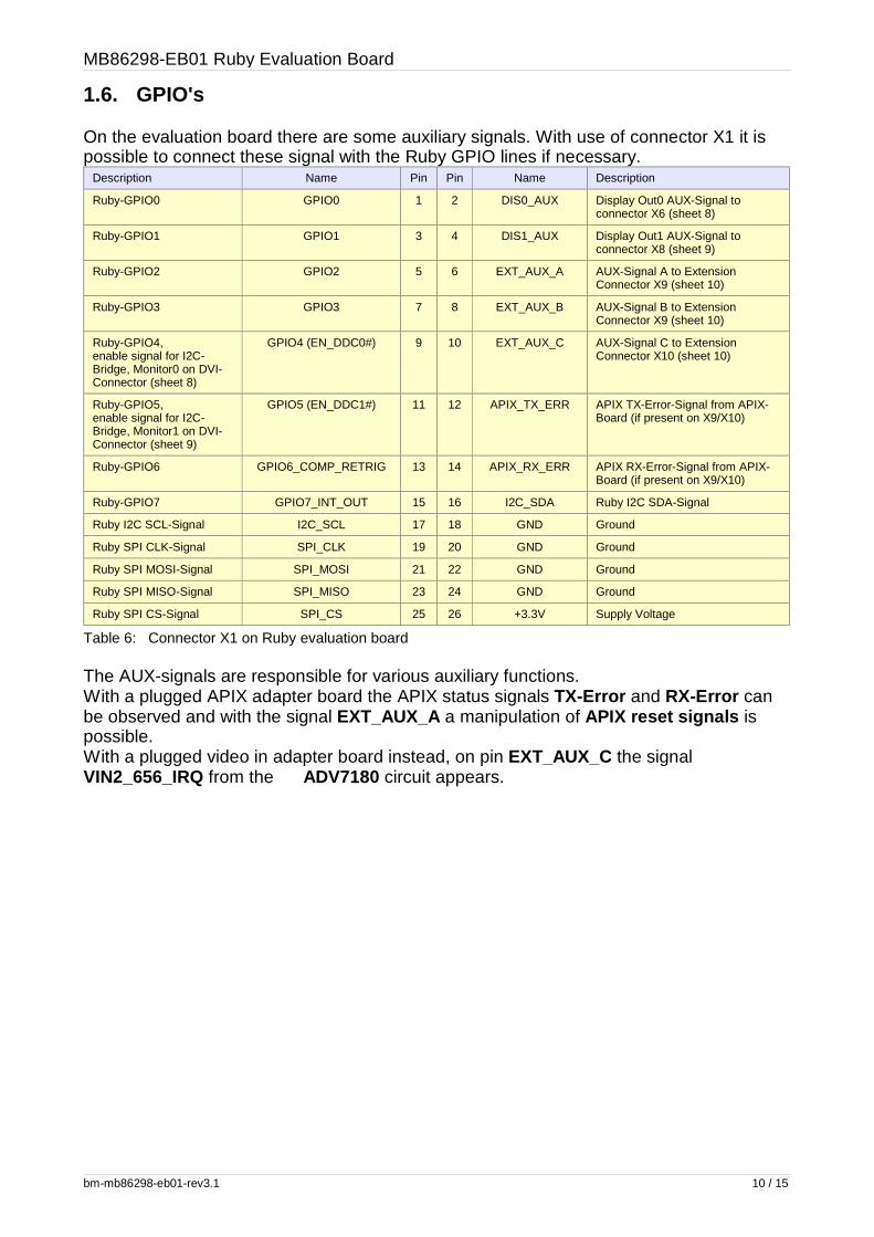
1.6. GPIO's
On the evaluation board there are some auxiliary signals. With use of connector X1 it ispossible to connect these signal with the Ruby GPIO lines if necessary.
Description Name Pin Pin Name Description
Ruby-GPIO0 GPIO0 1 2 DIS0_AUX Display Out0 AUX-Signal toconnector X6 (sheet 8)
Ruby-GPIO1 GPIO1 3 4 DIS1_AUX Display Out1 AUX-Signal toconnector X8 (sheet 9)
Ruby-GPIO2 GPIO2 5 6 EXT_AUX_A AUX-Signal A to ExtensionConnector X9 (sheet 10)
Ruby-GPIO3 GPIO3 7 8 EXT_AUX_B AUX-Signal B to ExtensionConnector X9 (sheet 10)
Ruby-GPIO4,enable signal for I2C-Bridge, Monitor0 on DVI-Connector (sheet 8)
GPIO4 (EN_DDC0#) 9 10 EXT_AUX_C AUX-Signal C to ExtensionConnector X10 (sheet 10)
Ruby-GPIO5,enable signal for I2C-Bridge, Monitor1 on DVI-Connector (sheet 9)
GPIO5 (EN_DDC1#) 11 12 APIX_TX_ERR APIX TX-Error-Signal from APIX-Board (if present on X9/X10)
Ruby-GPIO6 GPIO6_COMP_RETRIG 13 14 APIX_RX_ERR APIX RX-Error-Signal from APIX-Board (if present on X9/X10)
Ruby-GPIO7 GPIO7_INT_OUT 15 16 I2C_SDA Ruby I2C SDA-Signal
Ruby I2C SCL-Signal I2C_SCL 17 18 GND Ground
Ruby SPI CLK-Signal SPI_CLK 19 20 GND Ground
Ruby SPI MOSI-Signal SPI_MOSI 21 22 GND Ground
Ruby SPI MISO-Signal SPI_MISO 23 24 GND Ground
Ruby SPI CS-Signal SPI_CS 25 26 +3.3V Supply Voltage
Table 6: Connector X1 on Ruby evaluation board
The AUX-signals are responsible for various auxiliary functions. With a plugged APIX adapter board the APIX status signals TX-Error and RX-Error canbe observed and with the signal EXT_AUX_A a manipulation of APIX reset signals ispossible. With a plugged video in adapter board instead, on pin EXT_AUX_C the signalVIN2_656_IRQ from the ADV7180 circuit appears.
bm-mb86298-eb01-rev3.1 10 / 15

MB86298-EB01 Ruby Evaluation Board
1.7. Analog Video Input Slot
1.7.1. OverviewThe Analog Video Input Slot is the needed extension board to supply Ruby's Capture 1 -and Capture 2 - Input Ports with video signals from the S-Video- or CVBS-Connectors.
1.7.2. Connection to Ruby Evaluation BoardThe following diagram shows how to connect the Ruby Evaluation Board and the AnalogVideo Input Slot correctly with the provided red marked flat cable.
Figure 5: Connection between Ruby evaluation board and Analog Video Input Slot
bm-mb86298-eb01-rev3.1 11 / 15
Figure 4: Interfaces on the analogue video input slot
InputCVBS0
InputS-Video
InputCVBS1
Ruby Second-SlotCable Connector
Second-SlotCable Connector
Red Wire Marking
Ruby-to-Analog-Video-Slot-Adapter Cable
Ruby Evaluation Board
Analog Video Input Slot

MB86298-EB01 Ruby Evaluation Board
2. Adapter Boards
2.1. Video In Adapter Board 01 (MB86298-VIDEO01)
This Video In Adapter Board supports additional video signal connectors to supply Ruby'sVideo Input Capture Ports. The board contains an Analog Interface Circuit (AD9883) anda SDTV Video Decoder chip (ADV7180), connected to one S-Video- (X4), one CVBS-(X6) and one analog RGB connector (X2) for analogue signal supply. It is also possible tosupply alternatively digital ITU656-signals and RGB888-signals to the board withconnectors X5 and X1. The operation mode is configurable via switch S1.
Figure 6: Interfaces and configurations on the Video In Adapter Board 01
Figure 7: Interfaces on the Video In Adapter Board 01 bottom side
bm-mb86298-eb01-rev3.1 12 / 15
Input 2ITU656 to
Ruby CAP3
Input 0RGB888 toRuby CAP0
InputAnalogRGB
InputCVBS Input
S-VideoAnalog
RGB/Video Selector
Output toRuby
Extension Input
Input fromRuby
Extension Output

MB86298-EB01 Ruby Evaluation Board
Switch Function Description
S1A (1) Disable Analog RGBInput (AD9883)
If set to condition OFF (Default) , the AD9883 output supply Ruby's Capture 0 Input Port.
If set to condition ON, the bus switches connected to the Analog Interface circuit (AD9883) isHigh-Z (OFF) . The interface is configured to use digital RGB888-signals via connector X1.
Alternatively the switch setting can be override with hard-wired to GNDD on X1 pin33 .
S1B (2) Disable Analog Video Input (ADV7180)
If set to condition OFF (Default) , the ADV7180 output supply Ruby's Capture 3 Input Port.
If set to condition ON, on signal VDEC_OFF# appears low level. The interface is configuredto use digital ITU656-signals via connector X5.
Alternatively the switch setting can be override with hard-wired to GNDD on X5 pin19 .
Table 7: Switch S1 on Video In Adapter Board
Furthermore both video inputs (analog from X4 and X6 or digital from X5) can be disabledby setting switch S3A(1) to condition ON (on signal AVIN_OFF# appears low level) onRuby Evaluation Board. This mode is needed for use of Ruby's Video Input Capture Ports1, 2 and 3 with RGB666-signal input together (supplied thru Ruby X3, X4 and X5).
2.2. Video In Adapter Board 02 (MB86298-VIDEO02)
This Video In Adapter Board supports additional video signal connectors to supply Ruby'sVideo Input Capture Ports. The board contains two SDTV Video Decoder chips(ADV7180), each is connected to one S-Video- (X1,X4) and one CVBS-Connector (X2,X5). So , together with the two capture ports supplied with second slot adapter of RubyEvalboard it is possible to use 4x CVBS (or S-Video) inputs.Please note that here is used a different package type of ADV7180 (LQFP),programming is not 100% compatible to BGA package (used for MB86298-VIDEO01).
Figure 8: Interfaces on the Video In Adapter Board 02
bm-mb86298-eb01-rev3.1 13 / 15

MB86298-EB01 Ruby Evaluation Board
Figure 9: Interfaces on the Video In Adapter Board 02 bottom side
2.3. APIX Adapter Board
The APIX Adapter Board supports Inova's Digital Automotive Pixel Link Interface. Theboard contains transmitter and receiver chips for bidirectional data transfer via two RJ45-connectors (X2, X4). The APIX Sideband Signals are available on a separate connector(X5). The APIX Adapter Board uses Video Input Capture 0 Port and Display Output 1 onRuby Evaluation Board.
Figure 10: Interfaces and configurations on the APIX Adapter Board
bm-mb86298-eb01-rev3.1 14 / 15
APIXTransmitterConnector
APIXReceiver
ConnectorAPIX
Reset-LED
APIX Reset-Configuration
Jumper
APIXSideband Signal
Connector
Configuration EEPROM
APIXTransmitter
Configuration EEPROM
APIXReceiver

MB86298-EB01 Ruby Evaluation Board
Jumper J1 setting is responsible for APIX reset generation. The following table containsthe description of configurations. At release of reset Inova's APIX circuits read theconfiguration data from corresponding EEPROMs which are placed on sockets.
Closed Connection Setting Description
1 - 2 Default APIX reset generation occur via EXT_AUX_A signal from Ruby Evaluation Board. In this casethe signal EXT_AUX_A must be connected to a GPIO signal on Ruby Evaluation Boards X1connector and the user can manipulate the APIX reset in software.
2 - 3 - APIX reset generation with Ruby Evaluation Board reset signal XRST#.
Table 8: Jumper J1 on APIX Adapter Board
Figure 11: Interfaces on the APIX Adapter Board bottom side
bm-mb86298-eb01-rev3.1 15 / 15
Output toRuby
Extension Input
Input fromRuby
Extension Output


![Introduction to Ruby [Εισαγωγή στην Ruby]](https://img.dokumen.tips/doc/110x75/558cd1aad8b42ac4438b46b4/introduction-to-ruby-ruby.jpg)


![Ruby on Rails [ Ruby On Rails.ppt ] - [Ruby - [Ruby-Doc.org](https://img.dokumen.tips/doc/110x75/5491e450b479597e6a8b57d5/ruby-on-rails-ruby-on-railsppt-ruby-ruby-docorg-.jpg)

