Embed Size (px)
DESCRIPTION
o
Citation preview

PROGRAMMING MANUALfor
MAZATROL MATRIX(for Machining Centers)
EIA/ISO ProgramMANUAL No. : H740PB0041E
Serial No. :
Before using this machine and equipment, fully understand the contents of thismanual to ensure proper operation. Should any questions arise, please ask thenearest Technical Center or Technology Center.
1. Be sure to observe the safety precautions described in this manual and the contents of thesafety plates on the machine and equipment. Failure may cause serious personal injury ormaterial damage. Please replace any missing safety plates as soon as possible.
2. No modifications are to be performed that will affect operation safety. If such modifications arerequired, please contact the nearest Technical Center or Technology Center.
3. For the purpose of explaining the operation of the machine and equipment, some illustrationsmay not include safety features such as covers, doors, etc. Before operation, make sure allsuch items are in place.
4. This manual was considered complete and accurate at the time of publication, however, due toour desire to constantly improve the quality and specification of all our products, it is subject tochange or modification. If you have any questions, please contact the nearest Technical Centeror Technology Center.
5. Always keep this manual near the machinery for immediate use.
6. If a new manual is required, please order from the nearest Technical Center or TechnologyCenter with the manual No. or the machine name, serial No. and manual name.
Issued by Manual Publication Section, Yamazaki Mazak Corporation, Japan
11. 2006
IMPORTANT NOTICE


SAFETY PRECAUTIONS
S-1
SAFETY PRECAUTIONS
Preface
Safety precautions relating to the CNC unit (in the remainder of this manual, referred to simply asthe NC unit) that is provided in this machine are explained below. Not only the persons whocreate programs, but also those who operate the machine must thoroughly understand thecontents of this manual to ensure safe operation of the machine.
Read all these safety precautions, even if your NC model does not have the correspondingfunctions or optional units and a part of the precautions do not apply.
Rule
1. This section contains the precautions to be observed as to the working methods and statesusually expected. Of course, however, unexpected operations and/or unexpected workingstates may take place at the user site.During daily operation of the machine, therefore, the user must pay extra careful attention toits own working safety as well as to observe the precautions described below.
2. Although this manual contains as great an amount of information as it can, since it is notrare for the user to perform the operations that overstep the manufacturer-assumed ones,not all of “what the user cannot perform” or “what the user must not perform” can be fullycovered in this manual with all such operations taken into consideration beforehand.It is to be understood, therefore, that functions not clearly written as “executable” are“inexecutable” functions.
3. The meanings of our safety precautions to DANGER, WARNING, and CAUTION are asfollows:
DANGER
: Failure to follow these instructions could result in loss of life.
WARNING
: Failure to observe these instructions could result in serious harm to a humanlife or body.
CAUTION
: Failure to observe these instructions could result in minor injuries or seriousmachine damage.
HGENPA0043E

SAFETY PRECAUTIONS
S-2
Basics
WARNING
! After turning power on, keep hands away from the keys, buttons, or switches of theoperating panel until an initial display has been made.
! Before proceeding to the next operations, fully check that correct data has been enteredand/or set. If the operator performs operations without being aware of data errors,unexpected operation of the machine will result.
! Before machining workpieces, perform operational tests and make sure that the machineoperates correctly. No workpieces must be machined without confirmation of normaloperation. Closely check the accuracy of programs by executing override, single-block, andother functions or by operating the machine at no load. Also, fully utilize tool path check,Virtual Machining, and other functions, if provided.
! Make sure that the appropriate feed rate and rotational speed are designated for theparticular machining requirements. Always understand that since the maximum usable feedrate and rotational speed are determined by the specifications of the tool to be used, thoseof the workpiece to be machined, and various other factors, actual capabilities differ fromthe machine specifications listed in this manual. If an inappropriate feed rate or rotationalspeed is designated, the workpiece or the tool may abruptly move out from the machine.
! Before executing correction functions, fully check that the direction and amount ofcorrection are correct. Unexpected operation of the machine will result if a correctionfunction is executed without its thorough understanding.
! Parameters are set to the optimum standard machining conditions prior to shipping of themachine from the factory. In principle, these settings should not be modified. If it becomesabsolutely necessary to modify the settings, perform modifications only after thoroughlyunderstanding the functions of the corresponding parameters. Modifications usually affectany program. Unexpected operation of the machine will result if the settings are modifiedwithout a thorough understanding.
Remarks on the cutting conditions recommended by the NC
WARNING
! Before using the following cutting conditions:
- Cutting conditions that are the result of the MAZATROL Automatic Cutting ConditionsDetermination Function
- Cutting conditions suggested by the Machining Navigation Function
- Cutting conditions for tools that are suggested to be used by the Machining NavigationFunction
Confirm that every necessary precaution in regards to safe machine setup has been taken –especially for workpiece fixturing/clamping and tool setup.
! Confirm that the machine door is securely closed before starting machining.Failure to confirm safe machine setup may result in serious injury or death.

SAFETY PRECAUTIONS
S-3
Programming
WARNING
! Fully check that the settings of the coordinate systems are correct. Even if the designatedprogram data is correct, errors in the system settings may cause the machine to operate inunexpected places and the workpiece to abruptly move out from the machine in the eventof contact with the tool.
! During surface velocity hold control, as the current workpiece coordinates of the surfacevelocity hold control axes approach zeroes, the spindle speed increases significantly. Forthe lathe, the workpiece may even come off if the chucking force decreases. Safety speedlimits must therefore be observed when designating spindle speeds.
! Even after inch/metric system selection, the units of the programs, tool information, orparameters that have been registered until that time are not converted. Fully check thesedata units before operating the machine. If the machine is operated without checks beingperformed, even existing correct programs may cause the machine to operate differentlyfrom the way it did before.
! If a program is executed that includes the absolute data commands and relative datacommands taken in the reverse of their original meaning, totally unexpected operation ofthe machine will result. Recheck the command scheme before executing programs.
! If an incorrect plane selection command is issued for a machine action such as arcinterpolation or fixed-cycle machining, the tool may collide with the workpiece or part of themachine since the motions of the control axes assumed and those of actual ones will beinterchanged. (This precaution applies only to NC units provided with EIA functions.)
! The mirror image, if made valid, changes subsequent machine actions significantly. Usethe mirror image function only after thoroughly understanding the above. (This precautionapplies only to NC units provided with EIA functions.)
! If machine coordinate system commands or reference position returning commands areissued with a correction function remaining made valid, correction may become invalidtemporarily. If this is not thoroughly understood, the machine may appear as if it wouldoperate against the expectations of the operator. Execute the above commands only aftermaking the corresponding correction function invalid. (This precaution applies only to NCunits provided with EIA functions.)
! The barrier function performs interference checks based on designated tool data. Enter thetool information that matches the tools to be actually used. Otherwise, the barrier functionwill not work correctly.
! The system of G-code and M-code commands differs, especially for turning, between themachines of INTEGREX e-Series and the other turning machines.Issuance of the wrong G-code or M-code command results in totally non-intended machineoperation. Thoroughly understand the system of G-code and M-code commands beforeusing this system.
Sample program Machines of INTEGREX e-Series Turning machines
S1000M3 The milling spindle rotates at 1000 min–1. The turning spindle rotates at 1000 min–1.
S1000M203 The turning spindle rotates at 1000 min–1. The milling spindle rotates at 1000 min–1.

SAFETY PRECAUTIONS
S-4
! For the machines of INTEGREX e-Series, programmed coordinates can be rotated usingan index unit of the MAZATROL program and a G68 command (coordinate rotate com-mand) of the EIA program. However, for example, when the B-axis is rotated through 180degrees around the Y-axis to implement machining with the turning spindle No. 2, the plusside of the X-axis in the programmed coordinate system faces downward and if theprogram is created ignoring this fact, the resulting movement of the tool to unexpectedpositions may incite collisions.To create the program with the plus side of the X-axis oriented in an upward direction, usethe mirror function of the WPC shift unit or the mirror imaging function of G-code command(G50.1, G51.1).
! After modifying the tool data specified in the program, be sure to perform the tool pathcheck function, the Virtual Machining function, and other functions, and confirm that theprogram operates properly. The modification of tool data may cause even a field-provenmachining program to change in operational status.If the user operates the machine without being aware of any changes in program status,interference with the workpiece could arise from unexpected operation.For example, if the cutting edge of the tool during the start of automatic operation is presentinside the clearance-including blank (unmachined workpiece) specified in the common unitof the MAZATROL program, care is required since the tool will directly move from thatposition to the approach point because of no obstructions being judged to be present onthis path.For this reason, before starting automatic operation, make sure that the cutting edge of thetool during the start of automatic operation is present outside the clearance-includingworkpiece specified in the common unit of the MAZATROL program.
CAUTION
! If axis-by-axis independent positioning is selected and simultaneously rapid feed selectedfor each axis, movements to the ending point will not usually become linear. Before usingthese functions, therefore, make sure that no obstructions are present on the path.
! Before starting the machining operation, be sure to confirm all contents of the programobtained by conversion. Imperfections in the program could lead to machine damage andoperator injury.

SAFETY PRECAUTIONS
S-5
Operations
WARNING
! Single-block, feed hold, and override functions can be made invalid using system variables#3003 and #3004. Execution of this means the important modification that makes thecorresponding operations invalid. Before using these variables, therefore, give thoroughnotification to related persons. Also, the operator must check the settings of the systemvariables before starting the above operations.
! If manual intervention during automatic operation, machine locking, the mirror imagefunction, or other functions are executed, the workpiece coordinate systems will usually beshifted. When making machine restart after manual intervention, machine locking, themirror image function, or other functions, consider the resulting amounts of shift and takethe appropriate measures. If operation is restarted without any appropriate measures beingtaken, collision with the tool or workpiece may occur.
! Use the dry run function to check the machine for normal operation at no load. Since thefeed rate at this time becomes a dry run rate different from the program-designated feedrate, the axes may move at a feed rate higher than the programmed value.
! After operation has been stopped temporarily and insertion, deletion, updating, or othercommands executed for the active program, unexpected operation of the machine mayresult if that program is restarted. No such commands should, in principle, be issued for theactive program.
CAUTION
! During manual operation, fully check the directions and speeds of axial movement.
! For a machine that requires manual homing, perform manual homing operations afterturning power on. Since the software-controlled stroke limits will remain ineffective untilmanual homing is completed, the machine will not stop even if it oversteps the limit area.As a result, serious machine damage will result.
! Do not designate an incorrect pulse multiplier when performing manual pulse handle feedoperations. If the multiplier is set to 1000 times and the handle operated inadvertently, axialmovement will become faster than that expected.

BEFORE USING THE NC UNIT
S-6
BEFORE USING THE NC UNIT
Limited Warranty
The warranty of the manufacturer does not cover any trouble arising if the NC unit is used for itsnon-intended purpose. Take notice of this when operating the unit.
Examples of the trouble arising if the NC unit is used for its non-intended purpose are listedbelow.
1. Trouble associated with and caused by the use of any commercially available softwareproducts (including user-created ones)
2. Trouble associated with and caused by the use of any Windows operating systems
3. Trouble associated with and caused by the use of any commercially available computerequipment
Operating Environment
1. Ambient temperature
During machine operation: 0° to 50°C (32° to 122°F)
2. Relative humidity
During machine operation: 10 to 75% (without bedewing)
Note: As humidity increases, insulation deteriorates causing electrical component parts todeteriorate quickly.
Keeping the Backup Data
Note: Do not attempt to delete or modify the data stored in the following folder.Recovery Data Storage Folder: D:\MazakBackUp
Although this folder is not used when the NC unit is running normally, it contains important datathat enables the prompt recovery of the machine if it fails.
If this data has been deleted or modified, the NC unit may require a long recovery time. Be surenot to modify or delete this data.
E

C-1
CONTENTSPage
1 CONTROLLED AXES........................................................................... 1-1
1-1 Coordinate Words and Controlled Axes .............................................................1-1
2 UNITS OF PROGRAM DATA INPUT ................................................... 2-1
2-1 Units of Program Data Input ...............................................................................2-1
2-2 Units of Data Setting...........................................................................................2-1
2-3 Ten-Fold Program Data......................................................................................2-1
3 DATA FORMATS.................................................................................. 3-1
3-1 Tape Codes........................................................................................................3-1
3-2 Program Formats ...............................................................................................3-5
3-3 Tape Data Storage Format.................................................................................3-6
3-4 Optional Block Skip ............................................................................................3-6
3-5 Program Number, Sequence Number and Block Number: O, N ........................3-7
3-6 Parity-H/V ...........................................................................................................3-8
3-7 List of G-Codes ................................................................................................3-10
4 BUFFER REGISTERS.......................................................................... 4-1
4-1 Input Buffer.........................................................................................................4-1
4-2 Preread Buffer ....................................................................................................4-2
5 POSITION PROGRAMMING................................................................ 5-1
5-1 Dimensional Data Input Method .........................................................................5-1
5-1-1 Absolute/Incremental data input: G90/G91............................................................. 5-1

C-2
5-2 Inch/Metric Selection: G20/G21..........................................................................5-3
5-3 Decimal Point Input ............................................................................................5-4
6 INTERPOLATION FUNCTIONS........................................................... 6-1
6-1 Positioning (Rapid Feed): G00 ...........................................................................6-1
6-2 One-Way Positioning: G60 .................................................................................6-4
6-3 Linear Interpolation: G01 ....................................................................................6-5
6-4 Circular Interpolation: G02, G03.........................................................................6-6
6-5 Radius Designated Circular Interpolation: G02, G03..........................................6-9
6-6 Spiral Interpolation: G2.1, G3.1 (Option) ..........................................................6-11
6-7 Plane Selection: G17, G18, G19 ......................................................................6-19
6-7-1 Outline .................................................................................................................. 6-19
6-7-2 Plane selection methods....................................................................................... 6-19
6-8 Virtual-Axis Interpolation: G07..........................................................................6-21
6-9 Spline Interpolation: G06.1 (Option) .................................................................6-22
6-10 NURBS Interpolation: G06.2 (Option)...............................................................6-33
6-11 Cylindrical Interpolation: G07.1 ........................................................................6-40
6-12 Helical Interpolation: G02, G03 ........................................................................6-49
7 FEED FUNCTIONS .............................................................................. 7-1
7-1 Rapid Traverse Rates.........................................................................................7-1
7-2 Cutting Feed Rates.............................................................................................7-1
7-3 Asynchronous/Synchronous Feed: G94/G95 .....................................................7-1
7-4 Selecting a Feed Rate and Effects on Each Control Axis...................................7-3

C-3
7-5 Automatic Acceleration/Deceleration..................................................................7-6
7-6 Speed Clamp......................................................................................................7-7
7-7 Exact-Stop Check: G09 ......................................................................................7-7
7-8 Exact-Stop Check Mode: G61 ..........................................................................7-10
7-9 Automatic Corner Override: G62 ......................................................................7-10
7-10 Tapping Mode: G63..........................................................................................7-15
7-11 Cutting Mode: G64 ...........................................................................................7-15
7-12 Geometry Compensation/Accuracy Coefficient: G61.1/,K ................................7-16
7-12-1 Geometry compensation function: G61.1 ............................................................. 7-16
7-12-2 Accuracy coefficient (,K) ....................................................................................... 7-17
7-13 Inverse Time Feed: G93 (Option) .....................................................................7-18
8 DWELL FUNCTIONS ........................................................................... 8-1
8-1 Dwell Command in Time: (G94) G04..................................................................8-1
8-2 Dwell Command in Number of Revolutions: (G95) G04 .....................................8-2
9 MISCELLANEOUS FUNCTIONS ......................................................... 9-1
9-1 Miscellaneous Functions (M3-Digit)....................................................................9-1
9-2 No. 2 Miscellaneous Functions (A8/B8/C8-Digit)................................................9-2
10 SPINDLE FUNCTIONS ...................................................................... 10-1
10-1 Spindle Function (S5-Digit Analog)...................................................................10-1
10-2 Spindle Clamp Speed Setting: G92..................................................................10-1
11 TOOL FUNCTIONS............................................................................ 11-1
11-1 Tool Function (4-Digit T-Code) .........................................................................11-1

C-4
11-2 Tool Function (8-Digit T-Code) .........................................................................11-1
12 TOOL OFFSET FUNCTIONS............................................................. 12-1
12-1 Tool Offset........................................................................................................12-1
12-2 Tool Length Offset/Cancellation: G43, G44, or T-Code/G49 ............................12-5
12-3 Tool Position Offset: G45 to G48......................................................................12-7
12-4 Tool Diameter Offset Function: G40, G41, G42 .............................................12-13
12-4-1 Overview............................................................................................................. 12-13
12-4-2 Tool diameter offsetting ...................................................................................... 12-13
12-4-3 Tool diameter offsetting operation using other commands................................. 12-22
12-4-4 Corner movement ............................................................................................... 12-29
12-4-5 Interruptions during tool diameter offsetting ....................................................... 12-29
12-4-6 General precautions on tool diameter offsetting ................................................. 12-31
12-4-7 Offset number updating during the offset mode ................................................. 12-32
12-4-8 Excessive cutting due to tool diameter offsetting................................................ 12-34
12-4-9 Interference check .............................................................................................. 12-36
12-5 Three-Dimensional Tool Diameter Offsetting (Option)....................................12-43
12-5-1 Function description............................................................................................ 12-43
12-5-2 Programming methods ....................................................................................... 12-44
12-5-3 Correlationships to other functions ..................................................................... 12-48
12-5-4 Miscellaneous notes on three-dimensional tool diameter offsetting ................... 12-48
12-6 Programmed Data Setting: G10 .....................................................................12-49
12-7 Tool Offsetting Based on MAZATROL Tool Data ...........................................12-57
12-7-1 Selection parameters.......................................................................................... 12-57
12-7-2 Tool length offsetting .......................................................................................... 12-58

C-5
12-7-3 Tool diameter offsetting ...................................................................................... 12-59
12-7-4 Tool data update (during automatic operation)................................................... 12-60
12-8 Shaping Function (Option)..............................................................................12-61
12-8-1 Overview............................................................................................................. 12-61
12-8-2 Programming format ........................................................................................... 12-62
12-8-3 Detailed description ............................................................................................ 12-62
12-8-4 Remarks ............................................................................................................. 12-69
12-8-5 Compatibility with the other functions ................................................................. 12-70
12-8-6 Sample program ................................................................................................. 12-71
13 PROGRAM SUPPORT FUNCTIONS................................................. 13-1
13-1 Hole Machining Pattern Cycles: G34.1/G35/G36/G37.1...................................13-1
13-1-1 Overview............................................................................................................... 13-1
13-1-2 Holes on a circle: G34.1 ....................................................................................... 13-2
13-1-3 Holes on a line: G35 ............................................................................................. 13-3
13-1-4 Holes on an arc: G36............................................................................................ 13-4
13-1-5 Holes on a grid: G37.1.......................................................................................... 13-5
13-2 Fixed Cycles.....................................................................................................13-7
13-2-1 Outline .................................................................................................................. 13-7
13-2-2 Fixed-cycle machining data format ....................................................................... 13-8
13-2-3 G71.1 (Chamfering cutter CW) ........................................................................... 13-11
13-2-4 G72.1 (Chamfering cutter CCW) ........................................................................ 13-12
13-2-5 G73 (High-speed deep-hole drilling)................................................................... 13-13
13-2-6 G74 (Reverse tapping) ....................................................................................... 13-14
13-2-7 G75 (Boring) ....................................................................................................... 13-15

C-6
13-2-8 G76 (Boring) ....................................................................................................... 13-16
13-2-9 G77 (Back spot facing) ....................................................................................... 13-17
13-2-10 G78 (Boring) ....................................................................................................... 13-18
13-2-11 G79 (Boring) ....................................................................................................... 13-19
13-2-12 G81 (Spot drilling)............................................................................................... 13-19
13-2-13 G82 (Drilling)....................................................................................................... 13-20
13-2-14 G83 (Deep-hole drilling)...................................................................................... 13-21
13-2-15 G84 (Tapping)..................................................................................................... 13-22
13-2-16 G85 (Reaming) ................................................................................................... 13-23
13-2-17 G86 (Boring) ....................................................................................................... 13-23
13-2-18 G87 (Back boring)............................................................................................... 13-24
13-2-19 G88 (Boring) ....................................................................................................... 13-25
13-2-20 G89 (Boring) ....................................................................................................... 13-25
13-2-21 Synchronous tapping (Option) ............................................................................ 13-26
13-3 Initial Point and R-Point Level Return: G98 and G99 .....................................13-30
13-4 Scaling ON/OFF: G51/G50.............................................................................13-31
13-5 Mirror Image ON/OFF: G51.1/G50.1 ..............................................................13-44
13-6 Subprogram Control: M98, M99 .....................................................................13-45
13-7 End Processing: M02, M30, M998, M999.......................................................13-52
13-8 Linear Angle Commands ................................................................................13-53
13-9 Macro Call Function: G65, G66, G66.1, G67..................................................13-54
13-9-1 User macros ....................................................................................................... 13-54
13-9-2 Macro call instructions ........................................................................................ 13-55
13-9-3 Variables............................................................................................................. 13-64

C-7
13-9-4 Types of variables............................................................................................... 13-66
13-9-5 Arithmetic operation commands ......................................................................... 13-84
13-9-6 Control commands.............................................................................................. 13-88
13-9-7 External output commands (Output via RS-232C).............................................. 13-92
13-9-8 External output command (Output onto the hard disk) ....................................... 13-94
13-9-9 Precautions......................................................................................................... 13-96
13-9-10 Specific examples of programming using user macros ...................................... 13-98
13-10 Geometric Commads (Option)......................................................................13-102
13-11 Corner Chamfering and Corner Rounding Commands.................................13-103
13-11-1 Corner chamfering ( , C_) ................................................................................. 13-103
13-11-2 Corner rounding ( ,R_)...................................................................................... 13-105
14 COORDINATE SYSTEM SETTING FUNCTIONS.............................. 14-1
14-1 Fundamental Machine Coordinate System, Workpiece CoordinateSystems, and Local Coordinate Systems .........................................................14-1
14-2 Machine Zero Point and Second, Third, and Fourth Reference Points.............14-2
14-3 Fundamental Machine Coordinate System Selection: G53 ..............................14-3
14-4 Coordinate System Setting: G92 ......................................................................14-4
14-5 Automatic Coordinate System Setting ..............................................................14-5
14-6 Reference Point Return: G28, G29 ..................................................................14-6
14-7 Second, Third, or Fourth Reference Point Return: G30....................................14-8
14-8 Reference Point Check Command: G27 ........................................................14-10
14-9 Workpiece Coordinate System Setting and Selection: (G92) G54 to G59......14-11
14-10 Additional Workpiece Coordinate System Setting and Selection: G54.1........14-16

C-8
14-11 Local Coordinate System Setting: G52...........................................................14-22
14-12 Reading/Writing of MAZATROL Program Basic Coordinates.........................14-27
14-12-1 Calling a macroprogram (for data writing) .......................................................... 14-27
14-12-2 Data reading ....................................................................................................... 14-27
14-12-3 Rewriting............................................................................................................. 14-28
14-13 Workpiece Coordinate System Rotation.........................................................14-29
14-14 Three-Dimensional Coordinate Conversion: G68...........................................14-42
15 MEASUREMENT SUPPORT FUNCTIONS........................................ 15-1
15-1 Skip Function: G31...........................................................................................15-1
15-1-1 Function description.............................................................................................. 15-1
15-2 Skip Coordinate Reading..................................................................................15-2
15-3 Amount of coasting in the execution of a G31 block.........................................15-3
15-4 Skip coordinate reading error ...........................................................................15-4
15-5 Multi-Step Skip: G31.1, G31.2, G31.3, G04 .....................................................15-5
16 PROTECTIVE FUNCTIONS............................................................... 16-1
16-1 Pre-move Stroke Check ON/OFF: G22/G23 ....................................................16-1
17 THREADING: G33 (Option)................................................................ 17-1
17-1 Equal-Lead Threading ......................................................................................17-1
17-2 Continuous Threading ......................................................................................17-4
17-3 Inch Threading .................................................................................................17-4
18 DYNAMIC OFFSETTING: M173, M174 (Option) ............................... 18-1

C-9
19 HIGH-SPEED SMOOTHING CONTROL FUNCTION (OPTION) ....... 19-1
19-1 Programming Format........................................................................................19-2
19-2 Commands Available in the High-Speed Smoothing Control Mode .................19-2
19-3 Additional Functions in the High-Speed Smoothing Control Mode ...................19-3
19-4 Related Parameters..........................................................................................19-4
19-5 Remarks ...........................................................................................................19-4
19-6 Related Alarms.................................................................................................19-4
20 FUNCTION FOR SELECTING THE CUTTING CONDITIONS........... 20-1
21 TORNADO TAPPING (G130)............................................................. 21-1
22 HIGH-SPEED MACHINING MODE FEATURE (OPTION) ................. 22-1
23 AUTOMATIC TOOL LENGTH MEASUREMENT: G37 (OPTION) ..... 23-1
24 DYNAMIC OFFSETTING II: G54.2P0, G54.2P1 - G54.2P8(OPTION)............................................................................................ 24-1
25 EIA/ISO PROGRAM DISPLAY ........................................................... 25-1
25-1 Procedures for Constructing an EIA/ISO Program ...........................................25-1
25-2 Editing Function of EIA/ISO PROGRAM Display..............................................25-2
25-2-1 General ................................................................................................................. 25-2
25-2-2 Operation procedure............................................................................................. 25-2
25-3 Macro-Instruction Input.....................................................................................25-8
25-4 Division of Display (Split Screen)......................................................................25-9
25-5 Editing Programs Stored in External Memory Areas ......................................25-12

C-10
- NOTE -
E

CONTROLLED AXES 1
1-1
1 CONTROLLED AXES
1-1 Coordinate Words and Controlled Axes
Under standard specifications, there are three-dimensional controlled axes. With an addedfeature and a special option, the machine can control up to a maximum of six axes, including thethree fundamental axes. The direction of machining can be designated using a predeterminedcoordinate word consisting of an alphabetic character.
MEP001
+Y
+X
+X
+Y+Z
+Z
Bed
Workpiece
X-Y table
Table moving directions
Program coordinates
For X-Y table
For X-Y table and turntable
Table turningdirection
Table moving directions Program coordinates
Workpiece
+C+Y
+X+C
+X
+Y
MEP002
+Z
Workpiece

1 CONTROLLED AXES
1-2
- NOTE -
E

UNITS OF PROGRAM DATA INPUT 2
2-1
2 UNITS OF PROGRAM DATA INPUT
2-1 Units of Program Data Input
The movements on coordinate axes are to be commanded in the MDI mode or machiningprogram. The movement data are expressed in millimeters, inches or degrees.
2-2 Units of Data Setting
Various data commonly used for control axes, such as offsetting data, must be set for themachine to perform an operation as desired.The units of data setting and those of program data input are listed below.
Linear axis
Metric system Inch systemRotational axis
Units of program data input 0.0001 mm 0.00001 in. 0.0001 deg
Units of data setting 0.0001 mm 0.00001 in. 0.0001 deg
Note 1: Inch/metric selection can be freely made using either bit 4 of parameter F91 (“0” formetric, “1” for inches; validated through power-off and -on) or G-code commands (G20,G21).Selection using the G-code commands is valid only for program data input.Variables and offsetting data (such as tool offsetting data) should therefore be setbeforehand using the appropriate unit (inch or metric) for the particular machiningrequirements.
Note 2: Metric data and inch data cannot be used at the same time.
2-3 Ten-Fold Program Data
Using a predetermined parameter, machining program data can be processed as set in units ofone micron. There may be cases that a machining program which has been set in units of onemicron is to be used with a numerical control unit based on 0.1 micron increments. In such cases,use of this parameter allows the machine to perform the required machining operations withoutrewriting the program.Use bit 0 of user parameter F91 for this purpose.All types of coordinate data (axis movement data) not provided with the decimal point will bemultiplied by a factor of 10. This does not apply, indeed, to preset tool-offsetting data designatedwith addresses H and D.
Moving distance when program commands are executed
MAZATROL (B)Controlled axisProgram
command NC (A) for which theprogram was prepared Bit 0 of F91 = 0 Bit 0 of F91 = 1
Programapplicability(A) → (B)
Linear axis X1 (Y1 / Z1) 1 micron 0.1 micron 1 micron Applicable
Rotational axis B1 0.001° 0.0001° 0.001° Applicable

2 UNITS OF PROGRAM DATA INPUT
2-2
- NOTE -
E

DATA FORMATS 3
3-1
3 DATA FORMATS
3-1 Tape Codes
This numerical control unit (in the remainder of this manual, referred to as the NC unit) usescommand information that consists of letters of the alphabet (A, B, C .... Z), numerics (0, 1, 2 ....9), and signs (+, �, /, and so on). These alphanumerics and signs are referred to collectively ascharacters. On paper tape, these characters are represented as a combination of a maximum ofeight punched holes.Such a representation is referred to as a code.The NC unit uses either the EIA codes (RS-244-A) or the ISO codes (R-840).
Note 1: Codes not included in the tape codes shown in Fig. 3-1 will result in an error when theyare read.
Note 2: Of all codes specified as the ISO codes but not specified as the EIA codes, only thefollowing codes can be designated using the data I/O (Tape) parameters TAP9 toTAP14:
[ Bracket Open] Bracket Close# Sharp∗ Asterisk= Equal sign: Colon
However, you cannot designate codes that overlap existing ones or that result in parityerror.
Note 3: EIA/ISO code identification is made automatically according to the first EOB/LF codeappearing after the NC unit has been reset. (EOB: End Of Block, LF: Line Feed)
1. Significant information area (LABEL SKIP function)
During tape-based automatic operation, data storage into the memory, or data searching, the NCunit will ignore the entire information up to the first EOB code (;) in the tape when the unit isturned on or reset. That is, significant information in a tape refers to the information contained inthe interval from the time a character or numeric code appears, following the first EOB code (;)after the NC unit has been reset, until a reset command is given.
2. Control Out, Control In
The entire information in the area from Control Out �(� to Control In �)� will be ignored in regard tomachine control, while they will surely be displayed on the data display unit. Thus, this area canbe used to contain information, such as the name and number of the command tape, that is notdirectly related to control.During tape storage, however, the information in this area will also be stored. The NC unit willenter the Control In status when power is turned on.

3 DATA FORMATS
3-2
MEP003
EOB
C
O
NUL
1 1 1 1NUL
DEL
DEL
R R R ONUL
RNUL
1 1DEL
1 1NUL
2DEL
NUL
NUL
C
I
EOB
Name of tape is punched in captital letters.
/R
EOB
C
O
NUL
NUL
P R 1 10C
I.ONMARGO
EOB
Control InControl Out
Name of tape is printed out
Example of EIA Code
(
MEP004
Control Out
0 0 0EOB
G 0 X � 8 5 0 0 0 6 4 0 C U T T E RS
PE T U R N )�
Operator information is printed out.
The information at this portion is ignoredand nothing is executed.
Y REOB
C
R
Example of ISO Code
0 0 0G 0 X 5 0 0 0 4 0 C U T T E RS
PE T U R NR
C
R
Control In
3. EOR code (%)
In general, the EOR (End Of Record) code is punched at both ends of a tape and has thefollowing functions:
- To stop rewinding (only when a rewinding device is provided)
- To start rewinding during tape data search (only when a rewinding device is provided)
- To terminate the storage of tape data.

DATA FORMATS 3
3-3
4. Tape creation method for tape operation (Only when a rewinding device is used)
TEP005
!!!!!!!!!10 cm ; !!!!!!!!! ; ; !!!!!!!!! ; 10 cm %%
2m First block Last block 2m
The two meters of dummy at both ends and the EOR (%) at the head are not required when arewinding device is not used.

3 DATA FORMATS
3-4
EIA/ISO identification is made automatically by detecting whether EOB or LF initially appearsafter the NC unit has been reset.
MEP006
1234567890ABCDEFGHIJKLMNOPQRSTUVWXYZ+�.,/EOR (End of Record)EOB (End of Block) or CRCO (2+4+5)CI (2+4+7)
BS (Back Space)TABSP (Space)&
DEL (Delete)AS (All Space=Feed)*AM (All Mark=EOB+DEL)*
8 7 6 5 4 3 2 1
1234567890ABCDEFGHIJKLMNOPQRSTUVWXYZ+�.,/%LF (Line Feed) or NL( (Control Out)) (Control In):#?=[]BS (Back Space)HT (Horizontal Tab)SP (Space)&CR (Carriage Return)$' (Apostrophe);<>?@"DEL (Delete)NULLDEL (Delete)
LF or NL acts as EOB and %acts as EOR.
* The codes asterisked above are not EIA codes,but may be used for the convenience�s sake.
[1]
[2]
EIA code (RS-244-A)Feed holes
Channel number
ISO code (R-840)Feed holes
Channel number8 7 6 5 4 3 2 1
Definable in parameters
Fig. 3-1 Tape codes

DATA FORMATS 3
3-5
Codes in section [1] will only be stored as tape data when they are present in a comment section,and ignored elsewhere in the significant information area.Codes in section [2] are non-operative and will always be ignored (but undergo the parity-Vcheck).A dotted area indicates that the EIA Standard provides no corresponding codes.
3-2 Program Formats
A format predetermined for assigning control information to the NC unit is referred to as aprogram format. The program format used for our NC unit is word address format.
1. Words and addresses
A word is a set of characters arranged as shown below, and information is processed in words.
Word
Numeral
Alphabet (address)
Word configuration
The alphabetic character at the beginning of a word is referred to as an address, which definesthe meaning of its succeeding numeric information.
Table 3-1 Type and format of words
Item Metric command Inch command
Program No. O8
Sequence No. N5
Preparatory function G3 or G21
Moving axis0.0001 mm (deg.),0.00001 in.
X+54 Y+54 Z+54 α+54 X+45 Y+45 Z+45 α+45
Auxiliary axis0.0001 mm (deg.),0.00001 in.
I+54 J+54 K+54 I+45 J+45 K+45
Dwell0.001 mm (rev),0.0001 in.
X54 P8 U54
Feed0.0001 mm (deg.),0.00001 in.
F54 (per minute)F33 (per revolution)
F45 (per minute)F24 (per revolution)
Fixed cycle
Inputunit
0.0001 mm (deg.),0.00001 in.
R+54 Q54 P8 L4 R+45 Q45 P8 L4
Tool offset H3 or D3
Miscellaneous function M3 × 4
Spindle function S5
Tool function T4 or T8
No. 2 miscellaneous function B8, A8 or C8
Subprogram P8 H5 L4
Variables number #5

3 DATA FORMATS
3-6
1. Code O8 here indicates that program number can be set as an unsigned integer of eightdigits following O, and for X+54, �+� indicates that the value can be signed (negative) andthe two-digit number (54) indicates that the decimal point can be used and that five digitsbefore and four after the decimal point are effective (5 + 4 = 9 digits are effective for adesignation without decimal point).
2. The alpha sign (α) denotes additional axis address. +44 will be used when α is specified forrotational axis.
3. The number of digits in the words is checked by the maximum number of digits in theaddresses.
4. When data with decimal point is used for address for which decimal input is not available,decimal figures will be ignored.
5. If the number of integral digits exceeds the specified format, an alarm will result.
6. If the number of decimal digits exceed the specified format, the excess will be rounded.
2. Blocks
A block, unit of instruction, contains a number of words which constitute information necessaryfor the NC machine to perform an operation. The end of each block must be indicated by an EOB(End Of Block) code.
3. Programs
A number of blocks form one program.
4. Program end
M02, M30, M99, M998, M999 or % is used as program end code.
3-3 Tape Data Storage Format
As with tape operation, tape data to be stored into the memory can be either of ISO or EIA code.The first EOB code read in after resetting is used by the NC unit for automatic identification of thecode system ISO or EIA.The area of tape data to be stored into the memeory is, if the NC unit has been reset, from thecharacter immediately succeeding the first EOB code the EOR code, and in all other cases, fromthe current tape position to the EOR code. Usually, therefore, start tape data storage operationafter resetting the NC unit.
3-4 Optional Block Skip
1. Function and purpose
Optional block skip is a function that selectively ignores that specific block within a machiningprogram which begins with the slash code �/�.Any block beginning with �/� will be ignored if the [BLOCK SKIP] menu function is set to ON, orwill be executed if the menu function is set to OFF.For example, if all blocks are to be executed for a type of parts but specific blocks are not to beexecuted for another type, then different parts can be machined using one and the sameprogram that contains the �/� code at the beginning of the specific blocks.
DATA FORMATS 3
3-7
2. Operating notes
1. Blocks that have already been read into the pre-read buffer cannot be skipped.
2. This function is valid even during sequence number search.
3. During tape data storage (input) or output, all blocks, including those having a �/� code, arein- or outputted, irrespective of the status of the [BLOCK SKIP] menu function.
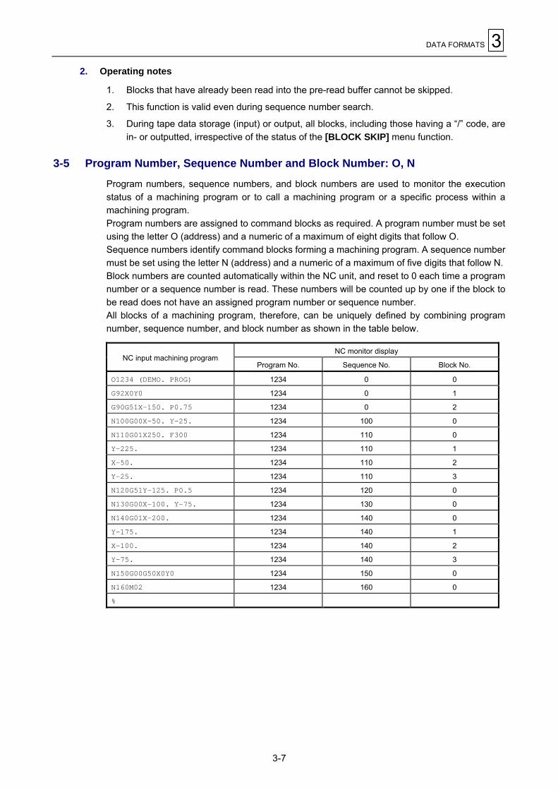
3-5 Program Number, Sequence Number and Block Number: O, N
Program numbers, sequence numbers, and block numbers are used to monitor the executionstatus of a machining program or to call a machining program or a specific process within amachining program.Program numbers are assigned to command blocks as required. A program number must be setusing the letter O (address) and a numeric of a maximum of eight digits that follow O.Sequence numbers identify command blocks forming a machining program. A sequence numbermust be set using the letter N (address) and a numeric of a maximum of five digits that follow N.Block numbers are counted automatically within the NC unit, and reset to 0 each time a programnumber or a sequence number is read. These numbers will be counted up by one if the block tobe read does not have an assigned program number or sequence number.All blocks of a machining program, therefore, can be uniquely defined by combining programnumber, sequence number, and block number as shown in the table below.
NC monitor displayNC input machining program
Program No. Sequence No. Block No.
O1234 (DEMO. PROG) 1234 0 0
G92X0Y0 1234 0 1
G90G51X–150. P0.75 1234 0 2
N100G00X–50. Y–25. 1234 100 0
N110G01X250. F300 1234 110 0
Y–225. 1234 110 1
X–50. 1234 110 2
Y–25. 1234 110 3
N120G51Y–125. P0.5 1234 120 0
N130G00X–100. Y–75. 1234 130 0
N140G01X–200. 1234 140 0
Y–175. 1234 140 1
X–100. 1234 140 2
Y–75. 1234 140 3
N150G00G50X0Y0 1234 150 0
N160M02 1234 160 0
%
3 DATA FORMATS
3-8
3-6 Parity-H/V
One method of checking if the tape is correctly created is by parity checks. Parity checks areperformed to check a tape for errors in punched codes, that is, for punching errors. There are twotypes of parity checks: parity-H and parity-V.
1. Parity-H check
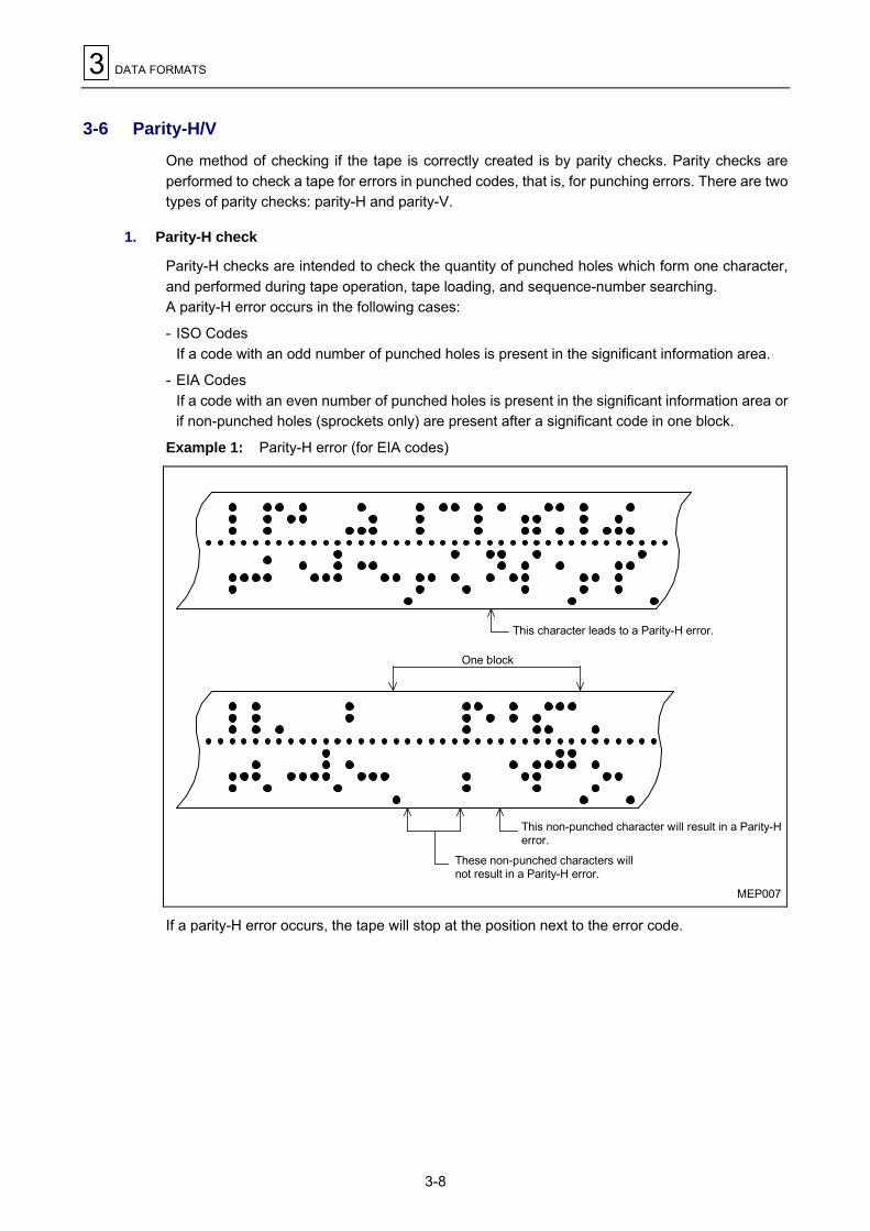
Parity-H checks are intended to check the quantity of punched holes which form one character,and performed during tape operation, tape loading, and sequence-number searching.A parity-H error occurs in the following cases:
- ISO CodesIf a code with an odd number of punched holes is present in the significant information area.
- EIA CodesIf a code with an even number of punched holes is present in the significant information area orif non-punched holes (sprockets only) are present after a significant code in one block.
Example 1: Parity-H error (for EIA codes)
MEP007
One block
This character leads to a Parity-H error.
This non-punched character will result in a Parity-Herror.
These non-punched characters willnot result in a Parity-H error.
If a parity-H error occurs, the tape will stop at the position next to the error code.

DATA FORMATS 3
3-9
2. Parity-V check
Parity-V checks will be performed during tape operation, tape loading, or sequence-numbersearching, if parity-V check item on the PARAMETER display is set to ON. Parity-V duringmemory operation, however, will not be checked.A parity-V error occurs in the following case:If an odd number of codes are present in the significant information area from the first significantcode in the vertical direction to the EOB code (;), that is, if an odd number of characters arepresent in one block.In the event of a parity-V error, the tape stops at a code next to the EOB (;).
Example 2: An example of parity-V error
MEP009
1 2 3 4 5 6 7
This block leads to a Parity-V error.
Note 1: During a parity-V check, some types of code are not counted as characters. See Fig.3-1, �Tape codes� for further details.
Note 2: Space codes in the area from the first EOB code to the first address code or slash code�/� are not subjected to counting for parity-V check.

3 DATA FORMATS
3-10
3-7 List of G-Codes
G functions are described in the list below.
Function G-code Group
Positioning ■G00 01
Linear interpolation ■G01 01
Circular interpolation (CW) G02 01
Circular interpolation (CCW) G03 01
Spiral interpolation (CW) G02.1 01
Spiral interpolation (CCW) G03.1 01
Dwell G04 00
High-speed machining mode G05 00
Fine spline interpolation G06.1 01
NURBS interpolation G06.2 01
Virtual-axis interpolation G07 00
Cylindrical interpolation G07.1 00
Exact-stop check G09 00
Data setting mode ON G10 00
Command address OFF G10.1 00
Data setting mode OFF G11 00
X-Y plane selection ■G17 02
Z-X plane selection ■G18 02
Y-Z plane selection ■G19 02
Inch command ■G20 06
Metric command ■G21 06
Pre-move stroke check ON G22 04
Pre-move stroke check OFF ▲G23 04
Reference point check G27 00
Reference point return G28 00
Return from reference point G29 00
Return to 2nd, 3rd and 4th reference points G30 00
Skip function G31 00
Multi-step skip 1 G31.1 00
Multi-step skip 2 G31.2 00
Multi-step skip 3 G31.3 00
Thread cutting (straight, taper) G33 01
Variable lead thread cutting G34 01
Hole machining pattern cycle (on a circle) G34.1 00
Hole machining pattern cycle (on a line) G35 00
Hole machining pattern cycle (on an arc) G36 00
Hole machining pattern cycle (on a grid) G37.1 00
Automatic tool length measurement G37 00
Vector selection for tool radius compensation G38 00
Corner arc for tool radius compensation G39 00
Tool radius compensation OFF ▲G40 07
Tool radius compensation (left) G41 07
3-D tool radius compensation (left) G41.2 07
Tool radius compensation (right) G42 07
3-D tool radius compensation (right) G42.2 07
Tool length offset (+) G43 08

DATA FORMATS 3
3-11
Function G-code Group
Tool tip point control (Type 1) ON G43.4 08
Tool tip point control (Type 2) ON G43.5 08
Tool length offset (�) G44 08
Tool position offset, extension G45 00
Tool position offset, reduction G46 00
Tool position offset, double extension G47 00
Tool position offset, double reduction G48 00
Tool position offset OFF ▲G49 08
Scaling OFF ▲G50 11
Scaling ON G51 11
Mirror image OFF ▲G50.1 19
Mirror image ON G51.1 19
Local coordinate system setting G52 00
Machine coordinate system selection G53 00
Selection of workpiece coordinate system 1 ▲G54 12
Selection of workpiece coordinate system 2 G55 12
Selection of workpiece coordinate system 3 G56 12
Selection of workpiece coordinate system 4 G57 12
Selection of workpiece coordinate system 5 G58 12
Selection of workpiece coordinate system 6 G59 12
Additional workpiece coordinate systems G54.1 12
Selection of fixture offset G54.2 23
One-way positioning G60 00
Exact stop mode G61 13
High-accuracy mode (Geometry compensation) G61.1 13
Automatic corner override G62 13
Tapping mode G63 13
Cutting mode ▲G64 13
User macro single call G65 00
User macro modal call A G66 14
User macro modal call B G66.1 14
User macro modal call OFF ▲G67 14
Programmed coordinate rotation ON G68 16
Programmed coordinate rotation OFF G69 16
3-D coordinate conversion ON G68 16
3-D coordinate conversion OFF ▲G69 16
Fixed cycle (Chamfering cutter 1, CW) G71.1 09
Fixed cycle (Chamfering cutter 2, CCW) G72.1 09
Fixed cycle (High-speed deep-hole drilling) G73 09
Fixed cycle (Reverse tapping) G74 09
Fixed cycle (Boring 1) G75 09
Fixed cycle (Boring 2) G76 09
Fixed cycle (Back spot facing) G77 09
Fixed cycle (Boring 3) G78 09
Fixed cycle (Boring 4) G79 09
Fixed cycle OFF ▲G80 09
Fixed cycle (Spot drilling) G81 09
Fixed cycle (Drilling) G82 09
Fixed cycle (Deep-hole drilling) G83 09

3 DATA FORMATS
3-12
Function G-code Group
Fixed cycle (Tapping) G84 09
Fixed cycle (Synchronous tapping) G84.2 09
Fixed cycle (Synchronous reverse tapping) G84.3 09
Fixed cycle (Reaming) G85 09
Fixed cycle (Boring 5) G86 09
Fixed cycle (Back boring) G87 09
Fixed cycle (Boring 6) G88 09
Fixed cycle (Boring 7) G89 09
Absolute data input ■G90 03
Incremental data input ■G91 03
Coordinate system setting/Spindle clamp speed setting G92 00
Workpiece coordinate system rotation G92.5 00
Inverse time feed G93 05
Feed per minute (asynchronous) ■G94 05
Feed per revolution (synchronous) ■G95 05
Initial point level return in fixed cycles ▲G98 10
R-point level return in fixed cycles G99 10
Measurement macro, workpiece/coordinate measurement G136
Compensation macro G137
Notes:
1. The codes marked with ▲ are selected in each group when the power is turned ON orexecuting reset for initializing modal.
2. The codes marked with " are able to be selected by a parameter as an initial modal which isto become valid when the power is turned ON or executing reset for initializing modal.Changeover of inch/metric system, however, can be made valid only by turning the powerON.
3. G-codes of group 00 are those which are not modal, and they are valid only for commandedblocks.
4. If a G-code not given in the G-code list is commanded, an alarm is displayed. And if a G-code without corresponding option is commanded, an alarm is displayed (808 MIS-SET GCODE).
5. If G-codes belong to different groups each other, any G-code can be commanded in thesame block. The G-codes are then processed in order of increasing group number. If two ormore G-codes belonging to the same group are commanded in the same block, a G-codecommanded last is valid.
E

BUFFER REGISTERS 4
4-1
4 BUFFER REGISTERS
4-1 Input Buffer
1. Overview
During tape operation or RS-232C operation, when the preread buffer becomes empty, thecontents of the input buffer will be immediately shifted into the pre-read buffer and, following this,if the memory capacity of the input buffer diminuishes to 248 × 4 characters or less, next data (upto 248 characters) will be preread from the tape and then stored into the input buffer.The input buffer makes block-to-block connections smooth by eliminating any operational delaysdue to the tape-reading time of the tape reader.These favorable results of prereading, however, will be obtained only if the execution time of theblock is longer than the tape-reading time of the next block.
TEP010
Input buffer
Memory
Buffer 1
Buffer 2
Buffer 4
Buffer 3
Prereadbuffer 5
Arithmeticoperationprocess
Tape
Keyboard
Modeselection
Note:One block of data is stored in one buffer.
2. Detailed description
- The memory capacity of the input buffer is 248 × 5 characters (including the EOB code).
- The contents of the input buffer register are updated in 248-character units.
- Only the significant codes in the significant information area are read into the buffer.
- Codes, including “(” and “)”, that exist between Control Out and Control In, are read into theinput buffer. Even if optional block skip is valid, codes from / to EOB will also be read into theinput buffer.
- The contents of the buffer are cleared by a reset command.

4 BUFFER REGISTERS
4-2
4-2 Preread Buffer
1. Overview
During automatic operation, one block of data is usually preread to ensure smooth analysis ofthe program. During tool radius compensation, however, maximal five blocks of data are prereadto calculate crossing point or to check the interference.In the high-speed machining mode (G05P2), moreover, up to 8 blocks of data are preread, and inthe mode of high-speed smoothing control up to 24 blocks of data are stored with the currentlyexecuted block in the middle (i. e. 12 blocks being preread).
2. Detailed description
- One block of data is stored into the prepared buffer.
- Only the significant codes in the significant information area are read into the pre-read buffer.
- Codes existing between Control Out and Control In are not read into the pre-read buffer. Ifoptional block skip is valid, codes from / to EOB will not also be read into the pre-read buffer.
- The contents of the buffer are cleared by a reset command.
- If the single block operation mode is selected during continuous operation, processing will stopafter pre-reading the next block data.
E

POSITION PROGRAMMING 5
5-1
5 POSITION PROGRAMMING
5-1 Dimensional Data Input Method
5-1-1 Absolute/Incremental data input: G90/G91
1. Function and purpose
Setting of G90 or G91 allows succeeding dimensional data to be processed as absolute data orincremental data.Setting of arc radius (with address R) or arc center position (with addresses I, J, K) for circularinterpolation, however, must always refer to incremental data input, irrespective of precedingG90 command.
2. Programming format
G90 (or G91) Xx1 Yy1 Zz1 αα1 (α : Additional axis)where G90: Absolute data input
G91: Incremental data input
3. Detailed description
1. In the absolute data mode, axis movement will be performed to the program-designatedposition within the workpiece coordinate system, irrespective of the current position.
N1 G90G00X0 Y0
In the incremental data mode, axis movement will be performed through the program-designated distance as relative data with respect to the current position.
N2 G91G01X200. Y50. F100
N2 G90G01X200. Y50. F100
200.
100.
Y
X
MEP011W 100. 200. 300.
N1
N2
Tool
Commands for a movement from the origin of the workpiece coordinate system are givenwith the same values, irrespective of whether the absolute data mode or the incrementaldata mode is used.

5 POSITION PROGRAMMING
5-2
2. The last G90 or G91 command works as a modal one for the following blocks.
(G90) N3 X100. Y100.
This block will perform a movement to the position of X = 100 and Y = 100 in the workpiececoordinate system.
(G91) N3 X-100. Y50.This block will perform a movement of –100 on the X-axis and +50 on the Y-axis, and thusresult in a movement to the position of X = 100 and Y = 100.
MEP012
200.
100.
Y
X100. 200. 300.
N3
W
3. Multiple G90 or G91 commands can be set in one block, and thus only a specific addresscan be set as absolute data or incremental data.
N4 G90X300. G91Y100.
In this example, dimensional data X300 preceded by G90 will be processed as an absolutedata input, and Y100 preceded by G91 as an incremental data input. Therefore, this blockwill result in a movement to the position of X = 300 and Y = 200 (100 + 100) in the workpiececoordinate system.
200.
100.
Y
XW 100. 200. 300.
N4
MEP013
Moreover, G91 (incremental data input mode) will work for the succeeding blocks.
4. Either the absolute data mode or the incremental data mode can be freely selected as initialmode by setting the bit 2 of user parameter F93.
5. Even in the MDI (Manual Data Input) mode, G90 and G91 will also be handled as modalcommands.

POSITION PROGRAMMING 5
5-3
5-2 Inch/Metric Selection: G20/G21
1. Function and purpose
Inch command/metric command selection is possible with G-code commands.
2. Programming format
G20: Inch command selectionG21: Metric command selection
3. Detailed description
1. Changeover between G20 and G21 is effective only for linear axes; it is meaningless forrotational axes.
Example: Preset unit of data input and G20/G21 (for decimal-point input type Ι)
Initial Inch (parameter) OFF Initial Inch (parameter) ONAxis Example
G21 G20 G21 G20
X X100 0.0100 mm 0.0254 mm 0.00039 inches 0.00100 inches
Y Y100 0.0100 mm 0.0254 mm 0.00039 inches 0.00100 inches
Z Z100 0.0100 mm 0.0254 mm 0.00039 inches 0.00100 inches
B B100 0.0100 deg 0.0100 deg 0.0100 deg 0.0100 deg
2. To perform G20/G21 changeover in a program, you must first convert variables, parameters,and offsetting data (such as tool length/tool position/tool diameter offsetting data) accordingto the unit of data input for the desired system (inch or metric) and then set all these types ofdata either on each data setting display or using the programmed parameter input function.
Example: If Initial inch selection is OFF and offsetting data is 0.05 mm, the offsetting datamust be converted to 0.002 (0.05 ÷ 25.4 ≈ 0.002) before changing the G21mode over to the G20 mode.
3. In principle, G20/G21 selection should be done before machining. If you want thischangeover to be performed in the middle of the program, temporarily stop the program byan M00 command after G20 or G21 and convert the offsetting data as required.
Example: G21 G92 Xx1 Yy1 Zz1
M MM MM M
G20 G92 Xx2 Yy2 Zz2
M00 → Convert offsetting data here.M
F10 → Set an F (Feed rate) command anew.Note: Do not fail to give an F command appropriate to the new unit system after
changeover between G20 and G21. Otherwise, axis movements would beperformed using the last F value before the changeover, without any conversion,on the basis of the new unit system.
4. Whether G20 or G21 is to be selected upon switching-on can be specified by the bit 4 ofuser parameter F91 (Initial Inch parameter).

5 POSITION PROGRAMMING
5-4
5-3 Decimal Point Input
1. Function and purpose
The decimal point can be used to determin the units digit (mm or inch) of dimensional data orfeed rate.
2. Programming format
!!!!!.!!!! Metric system
!!!!.!!!!! Inch system
3. Detailed description
1. Decimal-point commands are valid only for the distance, angle, time, speed, and scalingfactor (only after G51) that have been set in the machining program.
2. As listed in the table below, the meaning of command data without the decimal point differsbetween decimal-point input types Ι and ΙΙ according to the type of command unit system.
Command Command unit × 10 Type Ι Type ΙΙ
OFF 0.0001 (mm, inches, deg) 1.0000 (mm, inches, deg)X1
ON 0.0010 (mm, inches, deg) 1.0000 (mm, inches, deg)
3. Decimal-point commands are only valid for addresses X, Y, Z, U, V, W, A, B, C, I, J, K, E, F,P, Q and R, where address P only refers to a scaling factor.
4. The number of effective digits for each type of decimal-point command is as follows:
Move command(Linear)
Move command(Rotational)
Feed rate Dwell
Integral part Decimal part Integral part Decimal part Integral part Decimal part Integral part Decimal part
mm 0. - 99999. .0000 - .9999 0. - 99999. .0000 - .9999 0. - 200000. .0000 - .9999 0. - 99999. .000 - .999
inch 0. - 9999..00000 - .99999
0. - 99999. (359.) .0000 - .9999 0. - 20000.
.00000 - .99999
0. - 99999. .000 - .999
5. Decimal-point commands are also valid for definition of variables data used in subprograms.
6. For data which can be, but is not specified with the decimal point, either the minimumprogram data input unit or mm (or in.) unit can be selected using bit 5 of parameter F91.
7. A decimal-point command issued for an address which does not accept the decimal pointwill be processed as data that consists of an integral part only. That is, all decimal digits willbe ignored. Addresses that do not accept the decimal point are D, H, L, M, N, O, S and T. Alltypes of variables command data are handled as the data having the decimal point.

POSITION PROGRAMMING 5
5-5
4. Sample programs
A. Sample programs for addresses accepting the decimal point
Command category
Program exampleFor 1 = 1 µ For 1 = 0.1 µ 1 = 1 mm
G0X123.45(With the decimal point always givenas the millimeter point)
X123.450 mm X123.450 mm X123.450 mm
G0X12345 X12.345 mm* X1.2345 mm** X12345.000 mm***
#111=123 #112=5.55X#111 Y#112
X123.000 mmY5.550 mm
#113=#111+#112 (ADD) #113 = 128.550
#114=#111�#112 (SUBTRACT) #114 = 117.450
#115=#111#112 (MULTIPLY) #115 = 682.650
#116=#111/#112#117=#112/#111 (DIVIDE)
#116 = 22.162#117 = 0.045
* The least significant digit is given in 1 micron.** The least significant digit is given in 0.1 micron.*** The least significant digit is given in 1 mm.

5 POSITION PROGRAMMING
5-6
B. Validity of decimal point for each address
AddressDecimal
pointcommand
Application Remarks AddressDecimal
pointcommand
Application Remarks
Valid Coordinate position data Invalid Dwell time
Invalid Rotary tableMiscellaneous function code Valid Subprogram call numberA
Valid Linear angle data Invalid Number of helical pitches
Valid Coordinate position data Invalid Offset amount (in G10)
Valid Scaling factorBInvalid Rotary table
Miscellaneous function code
P
Invalid Rank for NURBS curve
Valid Coordinate position data Valid Cutting depth fordeep-hole drilling cycle
Invalid Rotary tableMiscellaneous function code Valid Shift amount for back boringC
Valid Corner chamfering amount
Q
Valid Shift amount for fine boring
D Invalid Offset number (tool position,tool length and tool diameter) Valid R point in fixed cycle
E Valid Valid Radius of an arc with Rselected
F Valid Feed rate Valid Radius of an arc for cornerrounding
Valid Offset amount (in G10)G Valid Preparatory function code
R
Valid Weight for NURBS curve
Invalid Offset number (tool postion,tool length and tool diameter) S Invalid Spindle function code
HInvalid Intra-subprogram sequence
number T Invalid Tool function code
Valid Coordinate of arc center U Valid Coordinate position dataI
Valid Vector component fortool diameter offset V Valid Coordinate position data
Valid Coordinate of arc center W Valid Coordinate position dataJ
Valid Vector component fortool diameter offset Valid Coordinate position data
Valid Coordinate of arc centerX
Valid Dwell time
Valid Vector component fortool diamater offset Y Valid Coordinate position dataK
Valid Knot for NURBS curve Z Valid Coordinate position data
L Invalid Fixed cycle/subprogramrepetition
M Invalid Miscellaneous function code
N Invalid Sequence number
O Invalid Program number
Note: The decimal point is valid in all the arguments for a user macroprogram.
E

INTERPOLATION FUNCTIONS 6
6-1
6 INTERPOLATION FUNCTIONS
6-1 Positioning (Rapid Feed): G00
1. Function and purpose
Positioning command G00 involves use of a coordinate word. This command positions a tool bymoving it linearly to the ending point specified by a coordinate word.
2. Programming format
G00 Xx Yy Zz αα; (α: Additional axis)
The command addresses are valid for all additional axis. The absolute or the incremental datainput is used according to the status of G90/G91 existing at the particular time.
3. Detailed description
1. Once this command has been given, the G00 mode will be retained until any other G-codecommand that overrides this mode, that is, either G01, G02, G03, or G32 of commandgroup 01 is given. Thus, a coordinate word will only need be given if the next command isalso G00. This function is referred to as the modal function of the command.
2. In the G00 mode, acceleration/deceleration always takes place at the starting/ending pointof a block and the program proceeds to the next block after confirming that the pulsecommand in the present block is 0 and the tracking error of the acceleration/decelerationcycle is 0. The width of in-position can be changed using a parameter (S13).
3. The G-code functions (G71.1 to G89) of command group 09 are canceled by the G00command (G80).
4. The tool path can be made either linear or nonlinear using a parameter (F91 bit 6) but thepositioning time remains unchanged.
- Linear pathAs with linear interpolation (G01), the tool speed is limited according to the rapid feed rateof each axis.
- Nonlinear pathThe tool is positioned according to the separate rapid feed rate of each axis.
5. When no number following G address, this is treated as G00.

6 INTERPOLATION FUNCTIONS
6-2
4. Sample programs
–100
Ending point(–120, +200, +300)
MEP014
Z
YX
+200
+300(Tool)
Starting point(+150, –100, +150) –120
+150
+150
Unit: mm
The diagram above is for:G90 G00 X-120.000 Y200.000 Z300.000; Absolute data commandG91 G00 X-270.000 Y300.000 Z150.000; Incremental data command
5. Remarks
1. If bit 6 of user parameter F91 is 0, the tool will take the shortest path connecting the startingand ending points. The positioning speed will be calculated automatically to give theshortest allocation time within the limits of the rapid feed rate of each axis.For example, if a rapid feed rate of 9600 mm/min is preset for both X- and Y-axes, then thecommandG91 G00 X–300.000 Y200.000
will move the tool as shown in the figure below.
MEP015-1
X
Y
Unit: mm
200
300
fy
Ending point
Starting pointfx
Y-axis effective feedrate:6400 mm/min
X-axis effective feedrate: 9600 mm/min
F91 bit 6 = 0

INTERPOLATION FUNCTIONS 6
6-3
2. If bit 6 of user parameter F91 is 1, the tool will move from the starting point to the endingpoint according to the rapid feed rate of each axis.For example, if a rapid feed rate of 9600 mm/min is preset for both X- and Y-axes, then thecommandG91 G00 X–300.000 Y200.000
will move the tool as shown in the figure below.
MEP015-2
X
Y
Unit: mm
200
300
fy
Ending point
Starting pointfx
Y-axis effective feedrate:9600 mm/min
X-axis effective feedrate: 9600 mm/min
F91 bit 6 = 1
3. The rapid feed rate that you can set for each axis using the G00 command varies frommachine to machine. Refer to the relevant machine specification for further details.
4. Rapid feed (G00) deceleration checkWhen processing of rapid feed (G00) is completed, the next block will be executed after thedeceleration check time (Td) has passed.The deceleration check time (Td) is calculated by following expressions depending on theacceleration/deceleration type.
Linear acceleration/linear deceleration .............................. Td = Ts + aExponential acceleration/linear deceleration ..................... Td = 2 × Ts + aExponential acceleration/exponential deceleration............ Td = 2 × Ts + a(Where Ts is the acceleration time constant, a = 0 to 14 msec)
The time required for the deceleration check during rapid feed is the longest among therapid feed deceleration check times of each axis determined by the rapid feedacceleration/deceleration time constants and by the rapid feed acceleration/decelerationmode of the axes commanded simultaneously.

6 INTERPOLATION FUNCTIONS
6-4
6-2 One-Way Positioning: G60
1. Function and purpose
Highly accurate positioning free from any backlash error can be performed when the axismovement is controled by the G60 command so that the final access always takes place in onedetermined direction.
2. Programming format
G60 Xx Yy Zz αα; (α: Additional axis)
3. Detailed description
1. The direction of final access and its creeping distance must be set in parameter I1.
2. After rapid approach to a position away from the ending point by the creeping distance, thefinal access is performed in the predetermined direction at a speed corresponding with therapid feed.
MEP018
Ending point
Final access direciton
Starting point (+)
Positioning pointG60 a
G60 –aG60 creeping distance
(–)
Starting pointTemporary stop
3. The positioning pattern described above also applies during machine locking or for a Z-axiscommand with the Z-axis cancellation activated.
4. In the dry run mode (G00 mode), the whole positioning is carried out at the dry-runningspeed.
5. The creeping to the einding point can be halted with Reset, Emergency stop, Interlock, orFeed hold, or by setting the rapid feed override to 0 (zero).The creeping is performed according to the setting of the rapid feed, and the rapid feedoverride function is also effective for the creeping.
6. One-way positioning is automatically invalidated for the hole-drilling axis in hole-drillingfixed-cycle operations.
7. One-way positioning is automatically invalidated for shifting in fine-boring or back-boringfixed-cycle operations.
8. Usual positioning is performed for an axis not having a parameter-set creeping distance.
9. One-way positioning is always of non-interpolation type.
10. An axis movement command for the same position as the ending point of the precedingblock (movement distance = 0) will cause reciprocation through the creeping distance sothat the final access can be performed in the predetermined direction for an accuratepositioning to the desired point.

INTERPOLATION FUNCTIONS 6
6-5
6-3 Linear Interpolation: G01
1. Function and purpose
This command moves (interpolates) a tool from the current position to the ending point specifiedby a coordinate word, at the feed rate specified with address F. The specified feed rate acts hereas the linear velocity relative to the direction of movement of the tool center.
2. Programming format
G01 Xx Yy Zz αα Ff; (α: Additional axis)
where x, y, z, and α each denote a coordinate. The absolute or the incremental data input is usedaccording to the status of G90/G91 existing at the particular time.
3. Detailed description
Once this command has been given, the G01 mode will be retained until any other G-codecommand that overrides this mode, that is, either G00, G02, G03 or G33 of command group 01is given. Thus, it is merely required to input coordinate words for linear interpolations in thesucceeding blocks unless the feed rate must be changed.A programming error will result if no F-code command has been given to the first G01 command.The feed rates for rotational axes must be set in deg/min. (Example: F300 = 300 deg/min)The G-code functions (G71.1 to G89) of command group 09 are cancelled by G01 (set to G80).
4. Sample program
The following shows a program for moving the tool at a cutting feed rate of 300 mm/min on theroute of P1 → P2 → P3 → P4 → P1 (where the section from P0 → P1 forms a positioning route forthe tool):
MEP019
30
30
202020
P2
P1
P4
P3Y
X
P0
Unit: mm
G91 G00 X20. Y20. P0 → P1
G01 X20. Y30. F300 P1 → P2
X30. P2 → P3
X–20. Y–30. P3 → P4
X–30. P4 → P1

6 INTERPOLATION FUNCTIONS
6-6
6-4 Circular Interpolation: G02, G03
1. Function and purpose
Commands G02 and G03 feed the tool along an arc.
2. Programming format
G02 (G03) Xx Yy (Zz) Ii Jj (Kk) Ff ;
X : Arc ending point coordinate, X-axisY : Arc ending point coordinate, Y-axisZ : Arc ending point coordinate, Z-axisI : Arc center, X-axisJ : Arc center, Y-axisK : Arc center, Z-axisF : Feed rate
Use addresses X, Y and Z (or their parallel axes) to specify the coordinates of the ending point ofarc, and addresses I, J and K for the coordinates of arc center.Combined use of absolute and incremental data input is available for setting the coordinates ofthe ending point of arc. For the coordinates of the arc center, however, incremental data relativeto the starting point must always be set.
3. Detailed description
1. Once the G02 (or G03) command has been given, this command mode will be retained untilany other G-code command used to override the G02 (or G03) command mode, that is, G00or G01 of command group 01 is given.
Counterclockwise (CCW)
Clockwise (CW)
FeedrateCoordinates ofthe arc center
Coordinates of theending point

INTERPOLATION FUNCTIONS 6
6-7
2. The direction of circular movement is determined by G02/G03.
G02: CW (Clockwise)G03: CCW (Counterclockwise)
MEP020
Z
G02
G03
Y
X
G02
G03
X
Z
G02
G03
Z
YG17 (X-Y) plane G18 (Z-X) plane G19 (Y-Z) Plane
G02 G03
G03G03
G02G02 Y
X
3. Interpolation of an arc that spans multiple quadrants can be defined with one block.
4. To perform circular interpolation, the following information is required:
- Rotational direction ......................CW (G02) or CCW (G03)
- Arc ending point coordinates .......Given with address X, Y, Z.
- Arc center coordinates.................Given with address I, J, K. (Incremental dimension)
- Feed rate......................................Given with address F.
5. If none of the addresses I, J, K and R is specified, a program error will occur.
6. Addresses I, J and K are used to specify the coordinates of the arc center in the X, Y and Zdirections respectively as seen from the starting point, therefore, care must be taken forsigns.

6 INTERPOLATION FUNCTIONS
6-8
4. Sample programs
Example 1: Complete-circle command
MEP021
Y-axis +Y
+X
FeedrateF = 500 mm/min
Circle centerJ = 50 mm
Starting / Ending point
X-axis
G02 J50.000 F500Example 2: Three-quarter circle command
MEP022
+Y
+X
Starting point
Circle centerJ = 50 mm
Ending point(x+50, y+50)
FeedrateF = 500 mm/min
Y-axis
X-axis
G91 G02 X50.000 Y50.000 J50.000 F500
5. Notes on circular interpolation
1. Clockwise (G02) or Counterclockwise (G03) during circular interpolation refers to therotational direction in the right-handed coordinate system when seen from the plus sidetoward the minus side of the coordinate axis perpendicular to the plane to be interpolated.
2. If the coordinates of the ending point are not set or if the starting and ending points are setat the same position, designating the center using address I, K or J will result in an arc of360 degrees (true circle).

INTERPOLATION FUNCTIONS 6
6-9
3. The following will result if the starting-point radius and the ending-point radius are not thesame.
- If error ∆R is larger than the parameter F19 (tolerance for radial value difference at endingpoint), a program error (817 INCORRECT ARC DATA) will occur at the starting point ofthe arc.
G02 X80. I50.
Startingpoint
Radius atstarting point
Radius atending point
Alarm stop
Center Ending point
∆R
MEP023
- If error ∆R is equal to or smaller than the parameter data, interpolation will take a spiralform heading for the programmed ending point of the arc.
MEP024
G02 X90. I50. Spiralinterpolation
∆RStarting
pointRadius at
starting pointRadius at
ending point
Center Ending point
The examples shown above assume that excessively large parameter data is given tofacilitate your understanding.
6-5 Radius Designated Circular Interpolation: G02, G03
1. Function and purpose
Circular interpolation can be performed by designating directly the arc radius R as well asspecifying conventional arc center coordinates (I, J, K).
2. Programming format
G02 (G03) Xx Yy Rr Ff;where x : X-axis coordinate of the ending point
y : Y-axis coordinate of the ending pointr : Radius of the arcf : Feed rate

6 INTERPOLATION FUNCTIONS
6-10
3. Detailed description
The arc center is present on the mid-perpendicular to the segment which connects the startingpoint and the ending point. The crossing point of the mid-perpendicular and that circle of thedesignated radius r that has the center set at the starting point gives the center coordinates ofthe designated arc.A semi-circle or smaller will be generated if R is a positive value.An arc larger than the semi-circle will be generated if R is a negative value.
Path of an arc with a negative-signed R
Ending point
Starting point
Path of an arc with a positive R
O2
O1L
r
TEP023
O1, O2 : Center point
To use the radius-designated arc interpolation commands, the following requirement must bemet:
≤ 1L
2 • r
where L denotes the length of the line from the starting point to the ending point.If radius data and arc center data (I, J, K) are both set in the same block, the circular interpolationby radius designation will have priority in general.For complete-circle interpolation (the ending point = the starting point), however, use center-designation method with addresses I, J and K, since the radius-specification command in thiscase will immediately be completed without any machine operation.
4. Sample programs
- G02 Xx1 Yy1 Rr1 Ff1 X-Y plane, radius-designated arc
- G03 Zz1 Xx1 Rr1 Ff1 Z-X plane, radius-designated arc
- G02 Xx1 Yy1 Jj1 Rr1 Ff1 X-Y plane, radius-designated arc(If radius data and center data (I, J, K) are set in the same block,circular interpolation by radius designation will have priority.)
- G17 G02 Ii1 Ji1 Rr1 Ff1 X-Y plane, center-designated arc(Radius-specification is invalid for complete circle)

INTERPOLATION FUNCTIONS 6
6-11
6-6 Spiral Interpolation: G2.1, G3.1 (Option)
1. Function and purpose
Commands G2.1 and G3.1 provide such an interpolation that the starting and ending points areconnected smoothly for an arc command where the radii of the both points differ from eachother.
rs
(Normal circular interpolation)
(Spiral interpolation)
Starting point
Ending point
Ending point
Center
re ≠ rs
re = rs
MEP031
2. Programming format
G17 G2.1 (or G3.1) Xp_ Yp_ I_ J_ (α_) F_ P_
G18 G2.1 (or G3.1) Zp_ Xp_ K_ I_ (α_) F_ P_
G19 G2.1 (or G3.1) Yp_ Zp_ J_ K_ (α_) F_ P_
P : Number of pitches (revolutions) (P can be omitted if equal to 0.)α : Any axis other than circular interpolation axes (For helical cutting only)F : Rate of feed along the tool path
3. Detailed description
1. Circular movement directions of G2.1 and G3.1 correspond with those of G02 and G03,respectively.
2. Radius designation is not available for spiral interpolation. (The starting and ending pointsmust lie on the same arc for a radius designation.)
Note: When a radius is designated, this command will be regarded as a radius-designated circular interpolation.
3. Conical cutting or tapered threading can be done by changing the radii of the arc at itsstarting and ending points and designating a linear-interpolation axis at the same time.
4. Even for normal circular command G2 or G3, spiral interpolation will be performed if thedifference between the radii of the starting point and the ending point is smaller than thesetting of parameter F19.
Arc center coordinatesArc ending point coordinates

6 INTERPOLATION FUNCTIONS
6-12
Example: When the following program is executed, the feed rates for each of the points willbe as shown in the diagram below.
A 3000 mm/minB 2500C 2000D 1500E 1000
Y
XACEDB
MEP032
G28 X0 Y0G00 Y–200.G17 G3.1 X–100. Y0 I–150. J0 F3000 P2M30

INTERPOLATION FUNCTIONS 6
6-13
4. Sample programs
Example 1: Spiral cutting
Shown below is an example of programming for spiral contouring with incremental data input ofthe arc center (X = 0, Y = 45.0) and absolute data input of the arc ending point (X = 0, Y = –15.0).
D735PB001
1545
Y
X
G91 G28 Z0G80 G40T15 T00 M06G54.1 P40G94 G00 X0 Y-45.0G43 Z30.0 H01Z3.0S1500 M03M50G01 Z-1.0 F150G2.1 X0 Y-15.0 I0 J45.0 F450 P2
G00 Z3.0M05 M09Z30.0M30
Zero point return on the Z-axis
Fixed-cycle cancellation
Tool change
Coordinate system setting
Approach in the XY-plane to the starting point (0, –45.0)
Positioning on the Z-axis to the initial point
Normal rotation of the spindle
Air blast ON
Infeed on the Z-axisCommand for spiral interpolation with arc ending point =(0, –15.0), arc center = (0, 0)*, and pitch = 2.* I- and J-values refer to increments to the starting point.
Return on the Z-axis
Spindle stop and Air blast OFF
End of machining
The rate of feed at the starting point is 450 mm/min, as specified in the block of G2.1, and therate of feed at the ending point can be calculated as follows:
(Ending point’s radius/Starting point’s radius) × Command value of the rate of feed.
As the radius of the starting point = 45.0, that of the ending point = 15.0, and the command rateof feed (F) = 450, the rate of feed results in
(15.0/45.0) × 450 = 150 mm/minat the ending point.
Note 1: Take care not to use radius designation (argument R) for spiral interpolation; otherwisea normal circular interpolation (by G02 or G03) will be executed.
Note 2: It is not possible to give the command for a spiral interpolation the starting and endingpoints of which should have different centers specified.

6 INTERPOLATION FUNCTIONS
6-14
Example 2: Heart-shaped cam (by absolute data input)
D735PB002
1
70
Y
X
G91 G28 Z0G80 G40T15 T00 M06G54.1 P40G94 G00 X0 Y-70.0G43 Z30.0 H01S1500 M03Z3.0M50G01 Z-1.0 F150G2.1 X0 Y1.0 I0 J70.0 F450X0 Y-70.0 I 0 J-1.0G00 Z3.0M05 M09Z30.0M30
Zero point return on the Z-axis
Fixed-cycle cancellation
Tool change
Coordinate system setting
Approach in the XY-plane to the starting point (0, –70.0)
Positioning on the Z-axis to the initial point
Normal rotation of the spindle
Air blast ON
Infeed on the Z-axis
Command for the left-hand half curve
Command for the right-hand half curve
Return on the Z-axis
Spindle stop and Air blast OFF
End of machining

INTERPOLATION FUNCTIONS 6
6-15
Example 3: Heart-shaped cam (by incremental data input)
MEP033
Y
Xb
(100.)
a
(30.)
0
Startingand Ending points
The difference (b–a) between the radii of the starting point and ending point denotes adisplacement for heart shape.Use two blocks for programming separately the right-half and the left-half shape.
A sample program in incremental data input:
G3.1 Y130. J100. F1000............... (Right half)a+b b
G3.1 Y–130. J–30 ........................ (Left half)–a–b –a
a = 30. (Minimum arc radius)b = 100. (Maximum arc radius)
a + b = 130. (Ending-point coordinate of the right half-circle)–a – b = –130. (Ending-point coordinate of the left half-circle)

6 INTERPOLATION FUNCTIONS
6-16
Example 4: Large-size threadingTo perform large-size threading, use three heilical-interpolation blocks forprogramming separately infeed section, threading section and upward-cuttingsection. Spiral interpolation is required to designate the amounts of diameterclearance for both the infeed block and the upward-cutting block. (The starting andending points are shifted through the designated clearance amounts from thecircumference of threading section.)
MEP034
X
Y
Z0
i3i1
i2
z1 z3z2
l
Infeed Threading Upward cutting
Clearance
G3.1 X–i1–i2 Y0 Zz1 I–i1 J0 Ff1 (Infeed block, half-circle)G03 X0 Y0 Zz2 Ii2 J0 Pp2 (Threading block, complete circle)G3.1 Xi2+i3 Y0 Zz3 Ii2 J0 (Upward-cutting block, half-circle)
* The number of pitches, p2, in the threading block is given by dividing the stroke z2 by the pitchl. Note that the value p2 must be an integer.

INTERPOLATION FUNCTIONS 6
6-17
Example 5: Tapered threadingAs shown in the figure below, tapered helical cutting that begins at any angle canbe performed.
MEP035
x1
i1
y1j1
z1
l
p1
e
s
X
0 Z
Y
Data with addresses X, Y and Z must be the increments x1, y1 and z1 respectively, from thestarting point s to the ending point e; data of I and J must be the increments i1 and j1 respectively,from the starting point s to the circular center, and data of P must be equal to the number ofpitches p1.
G3.1 Xx1 Yy1 Zz1 Ii1 Jj1 Pp1 Ff1The amount of taper t and the pitch l are calculated as follows:
2(re – rs)t =
x1
where rs = i12 + j12 , re = (x1 – i1)2 + (y1 – j1)2 ;
z1l =
(2π • π1 + θ) / 2πj1 – y1 –j1where θ = θe – θs = tan–1
i1 – x1– tan–1
–i1where rs and re denote the radii at the starting point and the ending point respectively, and qsand qe denote the angles at the starting point and the ending point respectively.

6 INTERPOLATION FUNCTIONS
6-18
Example 6: Conical cuttingConical cutting is an application of tapered threading, and have its starting orending point on the center line. Tapering results from gradually increasing ordecreasing the arc diameter. The pitch is determined by z1/p1.
MEP036
X0
Y
x1
Z
p1
z1
G2.1 X–x1 Y0 Zz1 I–x1 Pp1 Ff1x1 : Radius of the basez1 : Heightp1 : Number of pitchesf1 : Feed rate
Note: Use the TRACE display to check the tool path during spiral interpolation.

INTERPOLATION FUNCTIONS 6
6-19
6-7 Plane Selection: G17, G18, G19
6-7-1 Outline
1. Function and purpose
Commands G17, G18 and G19 are used to select a plane on which arc interpolation, tool noseradius compensation, etc. are to be done.Registering the three fundamental axes as parameters allows you to select a plane generated byany two non-parallel axes.These commands are also used to select a plane where figures or program coordinates are to berotated.
2. Programming format
G17; (X-Y plane selection)G18; (Z-X plane selection)G19; (Y-Z plane selection)
X, Y, and Z denote respective coordinate axesor their corresponding parellel axes.
G03 G03
G02 G02
X Y
Y X Z
G03
G02
Z
TEP024’
G17 (XY) plane G18 (ZX) plane G19 (YZ) plane
6-7-2 Plane selection methods
Plane selection by parameter setting is explained in this section.
1. Which of the fundamental axes or their parallel axes are to form the plane you want to selectis determined by the type of plane selection command (G17, G18 or G19) and the axisaddress specified in the same block.
G03 G03
G02 G02
X Y
Y X Z
G03
G02
Z
G17X Y; G18X Z; G19Y Z;
TEP025’
2. Automatic plane selection does not occur for blocks that do not have an issued plane-selection command (G17, G18 or G19)
G18 X_ Z_; Z-X planeY_ Z_; Z-X plane (No plane change)

6 INTERPOLATION FUNCTIONS
6-20
3. If axis addresses are not set for blocks having an issued plane-selection command (G17,G18 or G19), the fundamental three axes will be regarded as set.
G18_; (Z-X plane = G18 XZ ;)
Note 1: Use bits 0 and 1 of parameter F92 to set the initial plane which is to be selected uponpower-on or resetting.
Note 2: The G-codes for plane selection (G17, G18 or G19) should be commanded in a blockindependently. If such a G-code is commanded in a block containing the axis movecommand, a movement independent from the selected plane can be caused.
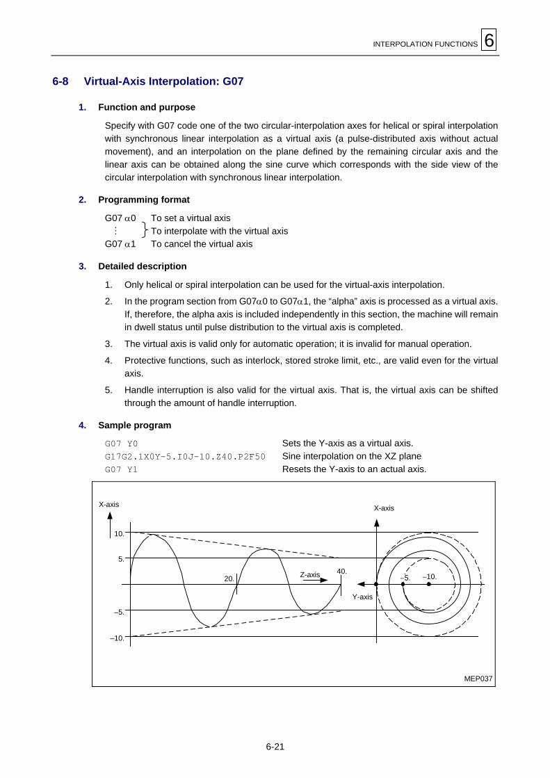
INTERPOLATION FUNCTIONS 6
6-21
6-8 Virtual-Axis Interpolation: G07
1. Function and purpose
Specify with G07 code one of the two circular-interpolation axes for helical or spiral interpolationwith synchronous linear interpolation as a virtual axis (a pulse-distributed axis without actualmovement), and an interpolation on the plane defined by the remaining circular axis and thelinear axis can be obtained along the sine curve which corresponds with the side view of thecircular interpolation with synchronous linear interpolation.
2. Programming format
G07 α0 To set a virtual axis M To interpolate with the virtual axisG07 α1 To cancel the virtual axis
3. Detailed description
1. Only helical or spiral interpolation can be used for the virtual-axis interpolation.
2. In the program section from G07α0 to G07α1, the “alpha” axis is processed as a virtual axis.If, therefore, the alpha axis is included independently in this section, the machine will remainin dwell status until pulse distribution to the virtual axis is completed.
3. The virtual axis is valid only for automatic operation; it is invalid for manual operation.
4. Protective functions, such as interlock, stored stroke limit, etc., are valid even for the virtualaxis.
5. Handle interruption is also valid for the virtual axis. That is, the virtual axis can be shiftedthrough the amount of handle interruption.
4. Sample program
G07 Y0 Sets the Y-axis as a virtual axis.G17G2.1X0Y–5.I0J–10.Z40.P2F50 Sine interpolation on the XZ planeG07 Y1 Resets the Y-axis to an actual axis.
MEP037
–10.
–5.
5.
10.
20.40.
–10.–5.Z-axis
X-axis X-axis
Y-axis

6 INTERPOLATION FUNCTIONS
6-22
6-9 Spline Interpolation: G06.1 (Option)
1. Function and purpose
The spline interpolation automatically creates a curve that smoothly traces specified points, andthus enables a high-speed and high-accuracy machining for free shapes along smoothly curvedtool path.
2. Programming format
G06.1 Xx1 Yy1
3. Detailed description
A. Setting and cancellation of spline interpolation mode
The spline interpolation mode is set by the preparatory function G06.1, and cancelled by anotherGroup 01 command (G00, G01, G02 or G03).
Example 1:
P1
P2P3
P4
P5
Pn
Pn+1
N100 G00 X_Y_ P1N200 G06.1 X_Y_ P2N201 X_Y_ P3N202 X_Y_ P4N203 X_Y_ P5
M MN290 X_Y_ PnN300 G01 X_Y_ Pn+1
Fig. 6-1 Interpolated line by spline interpolation
In the above example, the spline interpolation is activated at N200 (block for movement from P1
to P2) and it is cancelled at N300. Therefore, a spline curve is created for a group of endingpoints from P1 to Pn, and interpolation is applied along the created curve.
For creating a spline interpolation curve, it is generally required to specify two or more blocks (atleast three points to be traced) in the mode. If the spline interpolation mode is set just for oneblock, the path to the ending point of the block is interpolated in a straight line.
Example 2:
P1 P2
P3
Linear interpolation for the singlespline-interpolation block
N100 G01 X_Y_ P1
N200 G06.1 X_Y_ P2
N300 G01 X_Y_ P3
Fig. 6-2 Spline interpolation applied to a single block

INTERPOLATION FUNCTIONS 6
6-23
B. Division of spline curve in spline-interpolation mode
The spline interpolation mode generally creates a continuous curve that smoothly connects allspecified points from the beginning of the mode to the end of it. However, the spline curve isdivided into two discontinuous curves as often as one of the following conditions is satisfied:
- When the angle between linear movement lines of two neighboring blocks is beyond thespline-cancel angle,
- When the movement distance of a block exceeds the spline-cancel distance, or
- When there is a block without any movement command in the spline-interpolation mode.
1. When the relative angle of two neighboring blocks is beyond the spline-cancel angle
Spline-cancel angle LLL Parameter F101
As to the sequence of points P1, P2, P3, L Pn in a spline interpolation mode, when the angle
θi made by two continuous vectors Pi–1 Pi and PiPi+1 is larger than F101, the point Pi is
regarded as a corner. In that event, the point group is divided into two sections of P1 to Pi
and Pi to Pn at Pi, and spline curve is individually created for each section.When the spline-cancel angle is not set (F101 = 0), this dividing function is not available.
Example 1: F101 = 80 deg
Forms a corner
F101 not set
θ4 > F101
P4
θ4
θ6
θ5
θ3
θ2
P2
P1 P7
P6
P5
P1
P2
P3
P4
P5
P6
P7
P1
P2
P3
P4
P5
P6
P7
P3
Fig. 6-3 Spline cancel depending on angle

6 INTERPOLATION FUNCTIONS
6-24
When there are more than one point where θi > F101, such points are treated as corners todivide the point group and multiple spline curves are created for respective sections.
θi > F101 θi > F101
Fig. 6-4 Multiple-cornered spline curve depending on angle
When any two corner points (where θi > F101) successively exist, the block for the secondpoint is automatically set under control of linear interpolation. Therefore, it can be omitted tospecify G01 code in each intermediate block of pick feed, for example, during 2.5-dimensional machining, which considerably simplifies the programming.
Example 2: F101 < 90 (deg)In the following program (shown in Fig. 6-5), the angle of the Y-directional pickfeed to the X-Z plane (of spline interpolation) is always 90°. If F101 is set slightlysmaller than 90°, spline interpolation is automatically cancelled in the pick-feedblocks (N310, N410, !!!), which are then linearly interpolated each time. If no valueis set for F101, it is required to specify G-codes parenthesized in the programbelow to change the mode of interpolation.
N100 G00 X_Y_Z_ P1N200 G06.1 X_Z_ P2N210 X_Z_ P3
M MN300 X_Z_ PiN310 (G01) Y_ Pi+1N320 (G06.1) X_Z_ Pi+2
M MN400 X_Z_ PjN410 (G01) Y_ Pj+1N420 (G06.1) X_Z_ Pj+2
M MN700 X_Z_ Pn
N710 G01 M
Z
Y
X
Pi
Pi+1
Pn
Pj+1Pj
P1
Fig. 6-5 Linear interpolation for pick feed in spline-interpolation mode

INTERPOLATION FUNCTIONS 6
6-25
2. When the movement distance of a block exceeds the spline-cancel distance
Spline-cancel distance LLL Parameter F100
As to the sequence of points P1, P2, P3, !!! Pn in a spline interpolation mode, when the lengthPiPi+1 of the vector PiPi+1 is longer than F100, the block for point Pi+1 is automatically set
under control of linear interpolation, while the preceding and succeeding sections P1 to Pi
and Pi+1 to Pn are individually interpolated in spline curves.In this case, the inclination of the tangent vector at Pi (at the end of spline P1 to Pi) and theinclination of the tangent vector at Pi+1 (at the beginning of spline Pi+1 to Pn) do not
correspond to that of the line segment PiPi+1 in general.
When the spline-cancel distance is not set (F100 = 0), this dividing function is not available.
P1
P2
P3
P4 P5
P6
P7
P8
(a) P4P5 > F100,PiPi+1 ≤ F100 for other blocks
P1
P2
P3
P4 P5
P6
P7
P8
P4P5 > F100
Interpolated as follows:P1 to P4: Spline curve,P4 to P5: Straight line,P5 to P8: Spline curve.
The whole path P1 to P8 isinterpolated in one spline curve.
(b) F100 is not specified
Fig. 6-6 Spline cancel depending on movement distance of a block
When there are more than one block where PiPi+1 > F100, all those blocks will individually
undergo the linear interpolation.
3. When there is a block without any movement command in the spline-interpolation modeAny block without movement command temporarily cancels the spline interpolation, and thesections before and after such a block will independently be spline-interpolated.
N100 G01 X_Y_N110 G06.1 X_Y_ P1
N120 X_Y_ P2
M M
N300 X_Y_ P5
N310 X0 P5 (Not moved)N320 X_Y_ P6
M M
N500 X_Y_ P8
N510 G01 X_Y_P1
P2
P3
P4P5
P6
P7 P8
Spline from P5 to P8
Forms a cornerSpline from
P1 to P5
Fig. 6-7 Spline cancel by a block without movement command

6 INTERPOLATION FUNCTIONS
6-26
C. Fine spline function (curved shape correction)
The fine spline function works with spline interpolation and automatically corrects the shape of aspline curve, as required, to make the path of the curve smoother.More specifically, the fine spline function works in the following two cases:
- The case that the curve errors in blocks are significant
- The case that an unusually short block exists (automatic correction in this case is referred to asfairing.)
Automatic correction in the above cases is explained below.
1. Automatic correction for significant curve errors in blocks
When the curve data in CAD undergoes micro-segmentation with CAM, approximationusing a polygonal line is usually executed with a curve tolerance (chord error) of about 10microns. At this time, if any inflection points are included in the curve, the micro-segmentblock including the inflection points may increase in length (see P3 P4 . in the figure below)
Also, if the length of this block becomes unbalanced against those of the immediatelypreceding and succeeding blocks, the spline curve in this zone may have a significant errorwith respect to the original curve.
P7
P6
P4
P5
P3
P2
P0
P1
Tolerance (minus side)
Tolerance
Inflection pointin the original curve
CAD curve
Spline curve(deviation from the CAD curve is significant)
Tolerance (plus side)
Fig. 6-8 Spline curve having a significant chord error (inflection points present)
This function detects the sections whose chord errors in the curve due to the presence ofinflection points become significant, and corrects the shape of the spline curve in that zoneautomatically so that the chord errors in the curve fall within the data range of the specifiedparameter.
Curve error 1 LLL Parameter F102

INTERPOLATION FUNCTIONS 6
6-27
If a block in the spline interpolation mode is judged to have inflection points in the splinecurve and the maximum chord error of the spline curve from the segment is greater than thevalue of F102, the shape of that spline curve will be corrected for a maximum chord errornot exceeding the value of F102.
BA
F102 or less
Corrected spline curve
Uncorrected spline curve
Fig. 6-9 Shape correction 1 for spline curve
The shape of a curve can also be corrected if the chord error in the spline curve increasesdue to an imbalance in the lengths of adjoining blocks occurs for any reasons other than thepresence of inflection points or for other reasons.
Curve error 2 LLL Parameter F104
If a blocks in the spline interpolation mode is judged to have no inflection points in the splinecurve and the maximum chord error in the spline curve and block is greater than the value ofF104, the shape of that spline curve will be corrected for a maximum chord error notexceeding the value of F104.
Correctedspline curve
F104 or less
Correction
Uncorrectedspline curve
Fig. 6-10 Spline curve having a significant chord error (no inflection points)
Remark 1: In all types of spline curve correction, the curve correction function works only forthe corresponding block. Therefore, the tangential vectors at the boundaries withthe immediately preceding and succeeding blocks become discontinuous.
Remark 2: If parameter F102 is set to 0, all blocks regarded as including inflection points willbecome linear. If parameter F104 is set to 0, all blocks regarded as including noinflection points will become linear.
Remark 3: Curved-shape correction based on parameter F102 or F104 usually becomesnecessary when adjoining blocks are unbalanced in length. If the ratio of the ad-joining block lengths is very large, however, spline interpolation may be temporarilycancelled between the blocks prior to evaluation of the chord error.

6 INTERPOLATION FUNCTIONS
6-28
2. Automatic correction of the spline curve in an unusually short block (Fairing)When CAD data is developed into micro-segments by CAM, a very small block may becreated in the middle of the program because of internal calculation errors. Such a block isoften created during creation of a tool diameter offset program which requires convergencecalculation, in particular. Since this unusually small block usually occurs at almost rightangles to the direction of the spline curve, this curve tends not to become smooth.
Very small block
Distorted spline curve
Fig. 6-11 Distortion of a spline curve due to the effects of a very small block
If it detects such an extremely small block during spline interpolation, the shape correctionfunction will remove that block and then connect the preceding and succeeding blocksdirectly (this is referred to as fairing) to create a smooth spline curve free from distortion.
Block fairing length LLL Parameter F103
Assume that the length of the i-th block in spline interpolation mode is taken as li and thatthe following expressions hold:
li – 1 > F103 × 2li ≤ F103li + 1 > F103 × 2
In the above case, the ending point of the (i–1)-th block and the starting point of the i+1block are moved to the mid-point of the ith block and as a result, the ith block is deleted.Spline interpolation is executed for the sequence of points that has thus been corrected.
Created spline curve
li+1 > F103 × 2li–1 > F103 × 2
Correction of the passing point
li ≤ F103
Fig. 6-12 Correction of spline curve passing points by fairing

INTERPOLATION FUNCTIONS 6
6-29
Assume that the first block in spline interpolation mode is very small and that the followingexpressions hold:
l1 ≤ F103
l2 > F103 × 2
In the above case, the starting point of the second block is changed to that of the first blockand as a result, the first block is deleted.
Created spline curve
Deletion of the passing point
Non-spline blockl2 > F103 × 2
l1 ≤ F103
Fig. 6-13 Fairing at the starting point of a spline curve
Assume that the last block in spline interpolation mode is very small and that the followingexpressions hold:
ln–1 > F103 × 2
ln ≤ F103
In the above case, the ending point of the (n–1)-th block is changed to that of the nth blockand as a result, the nth block is deleted.
Deletion of the passing pointCreated spline curve
Non-spline blockln–1 > F103 × 2ln ≤ F103
Fig. 6-14 Fairing at the ending point of a spline curve
This function is executed preferentially over the curve slitting function based on the angle ofspline cancellation.

6 INTERPOLATION FUNCTIONS
6-30
D. Feed-rate limitation in spline-interpolation mode
The modal cutting feed rate F remains valid in general for the spline interpolation; however, if thefeed rate should be kept constant, it would yield excessively high acceleration at portions wherethe curvature is big (the curvature radius is small) as shown in Fig. 6-15.
F
Acceleration: Low
Acceleration: High
Curvature: Big
Curvature: Small
Fig. 6-15 Change of acceleration depending on curvature
In the spline-interpolation mode of our NC, the feed rate can be controlled so that it does notexceed the allowable limit, calculated from the related parameters, for pre-interpolationacceleration.To obtain an appropriate feed rate for each block of spline interpolation, the limit feed rate F' iscalculated by the equation [1] shown below where the smaller between two radii Rs (curvatureradius at the starting point of the block) and Re (curvature radius at its ending point) will beregarded as the reference radius R for the block. The modal feed rate F will then be temporarilyoverridden by F' for the respective block if F>F', so that the whole spline curve can beinterpolated block-by-block at the appropriate feed rate according to the curvature radius.
Pi Pj+1
Rs
Re
F’
F : Modal feed rate (mm/min)Rs : Curvature radius at the starting
point of block (mm)Re : Curvature radius at the ending
point of block (mm)R : Reference curvature radius for
the block (mm)R = min {Rs, Re}
∆V : Maximum of pre-interpolationacceleration
F’ : Limit feed rate (mm/min)
Fig. 6-16 Feed-rate limitation for spline interpolation
F' = R × ∆V × 60 × 1000 ......... [1]G1bF (mm/min)
∆V =G1btL (msec)

INTERPOLATION FUNCTIONS 6
6-31
E. Spline interpolation during tool-diameter offset
The spline interpolation can be performed during tool-diameter offset as follows.
1. Tool-diameter offset (2-dimensional)
Shown in Fig. 6-17 is an example that the command route is straight in the section P0P1,polygonal line in the section P1P2 . . . Pn that is the object of spline interpolation, and straightin the section PnPn+1. The interpolation route with tool-diameter offset is created by thefollowing procedure.
1) In the first step is created a polygonal line P0'P1'P2' . . . Pn'Pn+1' that is offset by thetool-diameter offset value r compared with the original polygonal line P0P1P2 . . . PnPn+1.
2) Next, a point Pi'' where PiPi'' = r on the vector PiPi' is determined for all the pass
points Pi (i = 2, 3, . . . n–1) other than the starting point P1 and the ending point Pn of thespline curve.
3) Spline interpolation is now conducted for the polygonal line P1'P2''P3'' . . . Pn–1''Pn' andthe curve thus created will act an offset path of tool center for the commanded splinecurve.
Pn-1'
r
P3'
P2'
P1' r r
1)
Pn+1'
Pn+1
P0'
P0 P1
P2
P3
Pn-1
Pn
Pn'
P2'' P2'
Pn
P1' Pn'
r
r
r2)P3''P3
Pn+1'
Pn+1
P0'
P P
P2
P3
Pn-1''
Pn-1'
Pn-1Spline curve for commandedpoints offset
P2
P2''
P3
3)
Pn+1'
Pn+1
P0'
P0
P1'
P
P3''
Pn-1''
Pn-1
Pn
Pn'
Spline curve forcommandedpoints
Fig. 6-17 Spline interpolation during tool-diameter offset
The spline curve created in the above-mentioned procedure is not the strict offset, indeed,of the commanded spline curve, but an approximation of it.

6 INTERPOLATION FUNCTIONS
6-32
2. 3-dimensional tool-diameter offset
In the 3-dimensional tool-diameter offset, each point defined with programmed coordinatesis first offset through the tool radius “r” in the direction of the specified normal vector (i, j, k)and then, the serial points thus offset in the spline-interpolation section are connected in asmooth curve, which will act as the path of tool-radius center for the 3-dimensional splineinterpolation.
F. Others
1. The spline interpolation targets the basic coordinate axes of X, Y and Z; however, it is notalways required to specify objective axes on commanding the spline interpolation.Moreover, the spline-interpolation command code (G06.1) can be given in a block withoutany movement command.
Example: N100 G06.1 X_Y_Z0 → N100 G06.1 X_Y_N200 X_Y_Z_ N200 X_Y_Z_N300 X_Y_Z_ N300 X_Y_Z_M M M M
N100 G06.1 F_ ( ← No movement commands)
N200 X_Y_Z_N300 X_Y_Z_M M
2. The spline-interpolation command (G06.1) falls under the G-code group 01.
3. In the single-block operation mode, the spline interpolation is cancelled and all the respec-tive blocks will individually undergo the linear interpolation.
4. In tool-path check, the blocks of spline interpolation are not actually displayed in a splinecurve but in a polygonal line that connects linearly the repective points, which, in case oftool-diameter offset, will have been offset in the same manner as described in the foregoingarticle E.
5. During spline interpolation, when feed hold is executed, the block for which the feed holdfunction has been executed will be interpolated, at the beginning of the restart operationalong the spline curve existing before the feed hold function was executed, and then thespline curve in the next block onward will be re-created and interpolation executed.
6. Althouth spline interpolation can also be executed in the high-speed maching mode (G05P2mode), curve shape correction by fairing becomes invalid in the G05P2 mode.
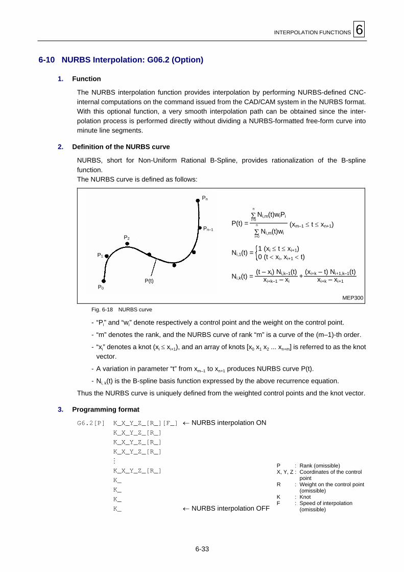
INTERPOLATION FUNCTIONS 6
6-33
6-10 NURBS Interpolation: G06.2 (Option)
1. Function
The NURBS interpolation function provides interpolation by performing NURBS-defined CNC-internal computations on the command issued from the CAD/CAM system in the NURBS format.With this optional function, a very smooth interpolation path can be obtained since the inter-polation process is performed directly without dividing a NURBS-formatted free-form curve intominute line segments.
2. Definition of the NURBS curve
NURBS, short for Non-Uniform Rational B-Spline, provides rationalization of the B-splinefunction.The NURBS curve is defined as follows:
P1
P2
P0
P(t)
Pn–1
Pn
MEP300
+Ni,k(t) =
Ni,1(t) =
(xm–1 ≤ t ≤ xn+1)P(t) =Ni,m(t)wi
n
Σi=0
Ni,m(t)wiPi
n
Σi=0
1 (xi ≤ t ≤ xi+1)0 (t < xi, xi+1 < t)
(t – xi) Ni,k–1(t)xi+k–1 – xi
(xi+k – t) Ni+1,k–1(t)xi+k – xi+1
Fig. 6-18 NURBS curve
- “Pi” and “wi” denote respectively a control point and the weight on the control point.
- “m” denotes the rank, and the NURBS curve of rank “m” is a curve of the (m–1)-th order.
- “xi” denotes a knot (xi ≤ xi+1), and an array of knots [x0 x1 x2 ... xn+m] is referred to as the knotvector.
- A variation in parameter “t” from xm–1 to xn+1 produces NURBS curve P(t).
- Ni, k(t) is the B-spline basis function expressed by the above recurrence equation.
Thus the NURBS curve is uniquely defined from the weighted control points and the knot vector.
3. Programming format
G6.2[P] K_X_Y_Z_[R_][F_] ← NURBS interpolation ONK_X_Y_Z_[R_]K_X_Y_Z_[R_]K_X_Y_Z_[R_]M
K_X_Y_Z_[R_]K_K_K_K_ ← NURBS interpolation OFF
P : Rank (omissible)X, Y, Z : Coordinates of the control
pointR : Weight on the control point
(omissible)K : KnotF : Speed of interpolation
(omissible)

6 INTERPOLATION FUNCTIONS
6-34
4. Detailed description
Set the G6.2 code to select the NURBS interpolation mode. Subsequently, designate the rank,the coordinates and weights of the control points, and the knots to determine the shape of theNURBS curve.The modal code G6.2, which belongs to group 1 of G-codes, is of temporary validity and themodal function relieved by a G6.2 code will automatically be retrieved upon cancellation(termination) of the NURBS interpolation. The G6.2 code can only be omitted for an immediatelysubsequent setting of the next NURBS curve.
Address P is used to set the rank, and the NURBS curve of rank “m” is of the (m–1)-th order, thatis, set as the rank
- P2 for a straight line (curve of the first order),- P3 for a quadratic curve (of the second order) or- P4 for a cubic curve (of the third order).
Setting another value than 2, 3 and 4 will cause an alarm, and P4 will be used in default ofargument P. The rank, moreover, should be specified in the first block (containing the G6.2code).Designate the control points in as many sequential blocks as required by specifying theirrespective coordinates and weights at addresses X, Y, Z and R. Argument R denotes the weightproper to each control point (R1.0 will be used in default), and the more the weight is applied, thecloser will be drawn the NURBS curve to the control point.
Address K is assigned to knots, and the NURBS curve of rank “m” for an “n” number of controlpoints requires an (n+m) number of knots. The required array of knots, referred to as knot vector,is to be designated in sequential blocks, namely: the first knot in the same block as the firstcontrol point, the second knot in the same block as the second control point, and so forth.Following the “n” blocks entered thus, designate the remaining “m” knots in single-commandblocks. The leading single-command block of argument K also notifies the NC of the completionof entering the control points, and the NURBS interpolation function itself will be terminated withthe last block for the “m” knots.
5. Remarks
1. Only the fundamental axes X, Y and Z can undergo the NURBS interpolation.
2. Do not fail to explicitly designate all the required axes X, Y and/or Z in the first block(containing G6.2). Designating a new axis in the second block onward will cause an alarm.
3. Since the first control point serves as the starting point of the NURBS curve, set in the firstblock (with G6.2) the same coordinates as the final point of the previous block. Otherwise,an alarm will be caused.
4. The setting range for the weight (R) is from 0.0001 to 99.9999. For a setting without decimalpoint, the least significant digit will be treated as units digit (for example, 1 = 1.0).
5. The knot (K) must be designated for each block. Omission results in an alarm.
6. Knots, as with the weight, can be set down to four decimal digits, and the least significantdigit of a setting without decimal point will be regarded as units digit.
7. Knots must be monotonic increasing. Setting a knot smaller than that of the previous blockwill result in an alarm.
8. The order of addresses in a block can be arbitrary.

INTERPOLATION FUNCTIONS 6
6-35
9. The shape of the NURBS curve can theoretically be modified very flexibly by changing therank, the positions and weights of the control points, and the knot vector (the relativeintervals of knots).In practice, however, manual editing is almost impossible, and a special CAD/CAM systemshould be used to edit the NURBS curve and create the program for the interpolation.Generally speaking, do not edit manually the program created by a CAD/CAM system forthe NURBS interpolation.
6. Variation of curve according to knot vector
The NURBS curve, which in general passes by the control points, can be made to pass througha specific control point by setting a certain number of knots in succession with the same value. Inparticular, setting as many leading and trailing knots as the rank (value of P) with the respectiveidentical values will cause the NURBS curve to start from the first control point (P0) and to end inthe last one (P5).The examples given below exhibit a variation of the NURBS curve according to the knot vectorwith the control points remaining identical.
Example 1: Rank : 4Number of control points : 6Knot vector : [ 0.0 1.0 2.0 3.0 4.0 5.0 6.0 7.0 8.0 9.0 ]
MEP301
The final point of thecurve differs from thelast control point.
The starting point of thecurve differs from the firstcontrol point. P5
P4P3P0
P2P1
Fig. 6-19 NURBS curve for continuously increasing knots
Example 2: Rank : 4Number of control points : 6Knot vector : [ 0.0 0.0 0.0 0.0 1.0 2.0 3.0 3.0 3.0 3.0 ]
[1] [2]
Point [1]: The first four (=rank) knots have the same value assigned.Point [2]: The last four (=rank) knots have the same value assigned.
MEP302
The curve ends inthe last control point.
The curve starts from thefirst control point. P5
P4P3P0
P2P1
Fig. 6-20 NURBS curve for some identical knots

6 INTERPOLATION FUNCTIONS
6-36
Note 1: The NURBS interpolation can be performed only for the NURBS curve that starts andends from the first and in the last control point. Do not fail, therefore, to set as manyleading and trailing knots as the rank with the respective identical values.
Note 2: The NURBS interpolation is executed at the designated feed rate (F-code). During theshape correction mode, however, the interpolation speed is controlled in order that themaximum available acceleration may not be exceeded in the section of a considerablecurvature.
7. Compatibility with the other functions
The tables in this section specify the compatibility of the NURBS interpolation with the otherfunctions. Pay attention to the incompatible functions, especially G-codes.
A. Preparatory, feed and auxiliary functions
The table below enumerates the G-codes, F-, M-, S-, T- and B-codes with regard to theiravailability before, with and after G6.2.
!: available ×: not available
Function Code before G6.2 with G6.2 after G6.2G-codes of group 00 all ! × ×G-codes of group 01 all ! ! (*) ×
G17G18G-codes of group 02G19
! ! ×
G22 × × ×G-codes of group 04
G23 ! × ×G93G98G-codes of group 05G99
! ! ×
G20G-codes of group 06
G21! ! ×
G40 ! × ×G41 × × ×G-codes of group 07G42 × × ×G80 ! × ×
G-codes of group 09the others × × ×
G-codes of group 12 G54 - G59 ! ! ×G61.1 ! × ×G61.2 ! × ×G61 × × ×G62 × × ×G63 × × ×
G-codes of group 13
G64 ! × ×G66 × × ×
G66.1 × × ×G66.2 × × ×
G-codes of group 14
G67 ! × ×G68.5 × × ×
G-codes of group 16G69.5 ! × ×
G54.2P0 ! × ×G-codes of group 23
G54.2P1 - P8 × × ×G5P0 ! × ×High-speed machining
mode G5P2 × × ×Feed function F ! ! ×Auxiliary function MSTB ! × ×
(*) The G-code given last in the block takes priority in group 01.

INTERPOLATION FUNCTIONS 6
6-37
B. Skip instructions
The table below enumerates the skip instructions with regard to their availability before, with andafter G6.2.
": available ×: not available
Instruction before G6.2 with G6.2 after G6.2
Optional block skip " " ×
Control Out/In " " ×
Note: Designating another address than X, Y, Z, R and K in the mode of (i. e. after) G6.2 willcause an alarm.
C. Interruption and restart
The table below enumerates the functions for interrupting and restarting the program flow withregard to their availability before, with and after G6.2.
": available ×: not available
Function before G6.2 with G6.2 after G6.2
Single-block operation " × " (Note)
Feed hold " × "
Reset " " "
Program stop " × ×
Optional stop " × ×
Manual interruption(Pulse feed and MDI)
" × ×
Restart " × ×
Comparison stop " × ×
Note: The single-block stop only occurs between blocks with different knots.
D. Tool path check
The tool path in a section of the NURBS interpolation can only be displayed as if the controlpoints were linearly interpolated (in the mode of G01).

6 INTERPOLATION FUNCTIONS
6-38
8. Sample program
The program section below refers to a NURBS interpolation of rank 4 (cubic curve) for sevencontrol points.
Control points: P0 P1 P2 P3 P4 P5 P6
Knot vector: [ 0.0 0.0 0.0 0.0 1.0 2.0 3.0 4.0 4.0 4.0 4.0 ]M
M
G90 G01 X0 Y120.F3000Y100. ............. P0
G6.2 P4 X0 Y100.R1.K0... P0
X10.Y100.R1.K0.......... P1
X10.Y60.R1.K0........... P2
X60.Y50.R1.K0........... P3
X80.Y60.R1.K1........... P4
X100.Y40.R1.K2.......... P5
X100.Y0 R1.K3........... P6
K4.K4.K4.K4.G01 X120................ P7
M
M
MEP303
Linear interpolation forthe control points
NURBS interpolationfor the control points
X
Y
P7P6
P5
P4
P3
P2
P1P0
Fig. 6-21 NURBS interpolation and linear interpolation

INTERPOLATION FUNCTIONS 6
6-39
9. Related alarms
The table below enumerates the alarms related to the NURBS interpolation.
Alarm list
AlarmNo. Alarm message Cause Remedy
806 ILLEGAL ADDRESS Another address than those for thenominated axes (X, Y and/or Z), theweight (R) and the knot (K) is set in theG6.2 mode.
Clear the inadequate address.
1. The modal condition is not appropriateto set G6.2.
1. Satisfy the modal condition withreference to item 7-A.
2 A block in the G6.2 mode is set withoutknot (K).
2. Do not fail to set a knot in each block inthe G6.2 mode.
807 ILLEGAL FORMAT
3. The number of blocks with the sameknot in succession does not reach therank.
3. Set an appropriate knot vector withreference to example 2 given in item 6.
1. The number of digits exceeds thespecification of axis commands (X, Y orZ).
1. Specify the axis command within eightdigits.
2. The rank (P) is not admissible. 2. Set 2, 3 or 4 at address P.
3. The value of a knot is not admissible. 3. Set a value in a range of 0.0001 to99.9999.
809 ILLEGAL NUMBERINPUT
4. The knot vector is not monotonicincreasing.
4. Check the blocks for a decreasing knot.
816 FEEDRATE ZERO The feed rate (F-code) has not yet beendesignated.
Set an F-code before or in the same blockas the G6.2 code.
936 OPTION NOT FOUND The system is not equipped with theoptional function of the NURBSinterpolation.
Purchase and install the optional function.
955 START AND ENDPOINT NOT AGREE
The axis coordinates designated in theblock of G6.2 do not correspond to thefinal point of the previous block.
Designate in the first block of the NURBSinterpolation the same position as the finalpoint of the previous block.
956 RESTART OPERATIONNOT ALLOWED
The designated restart block falls withinthe mode of G6.2.
Restart operation is not allowed from themidst of the NURBS interpolation.
957 MANUAL INTERRUPTNOT ALLOWED
An interruption by pulse handle or MDIoperation is commanded in the midst ofthe G6.2 mode.
Manual interruption is not allowed in themidst of the NURBS interpolation.

6 INTERPOLATION FUNCTIONS
6-40
6-11 Cylindrical Interpolation: G07.1
1. Function and purpose
Cylindrical interpolation refers to a function by which the cylindrical surface of a workpiece canbe machined according to a program prepared on its development plane. This function is amongothers very efficient in the creation of a cam grooving program.
2. Programming format
A. Selection and cancellation of the cylindrical interpolation mode
- When the A-axis functions as the rotational axis:G07.1 Ar; Cylindrical interpolation mode ON (r = radius of cam groove bottom)G07.1 A0; Cylindrical interpolation mode OFF
- When the B-axis functions as the rotational axis:G07.1 Br; Cylindrical interpolation mode ON (r = radius of cam groove bottom)G07.1 B0; Cylindrical interpolation mode OFF
Note 1: The above preparatory function (G-code) must be given in a single-command block.
Note 2: Enter a precise value for the radius of the cam groove bottom (r), which is used for theinternal calculation of the dimensions and the rate of feed in the developed plane.
Note 3: Enter a positive value for the radius of the cam groove bottom (r).
Note 4: In the mode of cylindrical interpolation the radius of the cam groove bottom (r) cannotbe otherwise modified than to zero. That is, the modification must be done aftercanceling the mode temporarily.
Note 5: Cylindrical interpolation is not available for machines with a linear type rotational axis(F85 bit 2 = 1; HV-machines or machines with a tilting table).
Note 6: The figure below refers to a vertical machining center. To perform machining on thesurface of the cylinder, position the tool on the Y-axis to the axis of the cylinder first,perform an infeed on the Z-axis even to the groove bottom and then select the mode ofa cylindrical interpolation with simultaneous control of the X- and A-axis.
Z
YX
Ar
Fig. 6-22 Diagrammatic view of cylindrical interpolation (1/2)

INTERPOLATION FUNCTIONS 6
6-41
Note 7: The next figure shows a machining center with the fixture mounted perpendicular to theY-axis. To use the cylindrical interpolation on such a machine, position the tool on theX-axis to the axis of the cylinder first, perform an infeed on the Z-axis even to thegroove bottom and then select the mode of a cylindrical interpolation with simultaneouscontrol of the Y- and B-axis.
Z
YX
Br
Z
Y
X
B
r
Fig. 6-23 Diagrammatic view of cylindrical interpolation (2/2)
B. Commands in the cylindrical interpolation mode
GgXxAaRrIiJjDdPpFf;GgYyBbRrIiJjDdPpFf;Gg: Refer to Table 6-2 (in paragraph 1 under 3-B) for the available G-codes.Xx/Aa: Cylindrical interpolation occurs in the X-A plane or Y-B plane.Yy/Bb: The values of X (or Y) and A (or B) are of linear and angular dimensions, respectively.Rr: Radius for a circular interpolationIi: Abscissa (incremental) of the center for a circular interpolationJj: Ordinate (incremental) of the center for a circular interpolationDd: Offset number for tool diameter offsetPp/Xx: Dwell timeFf: Rate of feed (Refer to the detailed description in paragraph 2 under 3-B.)

6 INTERPOLATION FUNCTIONS
6-42
3. Detailed description
A. Conditions necessary for the selection of the cylindrical interpolation mode
The G-code modal states required for the cylindrical interpolation mode selection are as follows:
Table 6-1 Conditions necessary for the mode selection
G-code group Condition
G-code group 1 G0/G1 (Positioning or Linear interpolation only)
G-code group 2 G17 (X-Y plane only)
G-code group 3 G90/G91 (Absolute/Incremental programming) [unconditional]
G-code group 4 G22/G23 (Stroke check ON/OFF) [unconditional]
G-code group 5 G94/G95 (Asynchronous/Synchronous feed) [unconditional]
G-code group 6 G20/G21 (Inch/Metric data input) [unconditional]
G-code group 7 G40 (Tool diameter offset OFF) (Note 1)
G-code group 8 G43/G49 (Tool length offset ON/OFF) [unconditional]
G-code group 9 G80 (Fixed cycle OFF)
G-code group 10 Invalid (Return level selection [between initial and R-point] is only valid for fixedcycles.)
G-code group 11 G50 (Scaling OFF)
G-code group 12 G54 to G59,G54.1 (Standard/Additional workpiece coordinate system) [unconditional]
G-code group 13 G64 (Cutting mode)
G-code group 14 G67 (User macro modal call OFF)
G-code group 15 G40.1 (Shaping OFF)
G-code group 16 G69 (Programmed coordinates rotation OFF) (Note 2)
G-code group 19 G50.1/G51.1 (Mirror image ON/OFF) [unconditional] (Note 3)
G-code group 19 No selection of a plane for five-surface machining
G-code group 23 G54.2P0 (Dynamic offsetting II OFF)
Others G5P0 (High-speed machining OFF)
Others G7.1B0 (Cylindrical interpolation OFF)
Otherwise the selection will only lead to an alarm.
Note 1: Select and cancel the tool diameter offset as required in the mode of cylindrical inter-polation. An alarm will be caused if the cylindrical interpolation is selected in the modeof tool diameter offset.
Note 2: The cylindrical interpolation cannot be selected in the mode of G68 (3-dimensionalcoordinate conversion). On an HV machining center, therefore, the cylindrical inter-polation function is not available to an inclined or top surface.
Note 3: To use the cylindrical interpolation with the mirror image function being selected, takethe following precautions in order to prevent errors from occurring in the developmentof the cylindrical surface:
[1] Set the mirroring center to 0° for the rotational axis of the cylindrical interpolation.
[2] Select the cylindrical interpolation with the rotational axis being positioned at itsworkpiece origin (0°).
[3] Also cancel the cylindrical interpolation with the rotational axis being positioned atits workpiece origin (0°).
An example of programming is given later in the sample program under 5-B.
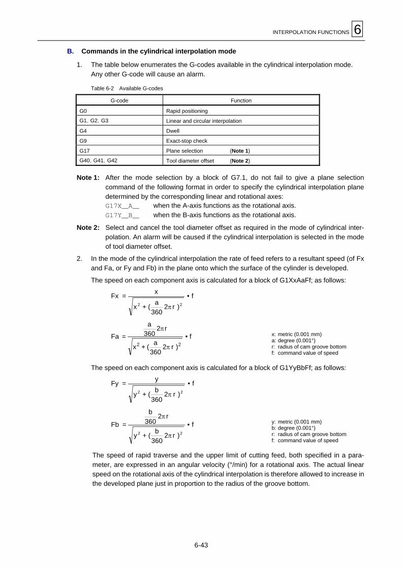
INTERPOLATION FUNCTIONS 6
6-43
B. Commands in the cylindrical interpolation mode
1. The table below enumerates the G-codes available in the cylindrical interpolation mode.Any other G-code will cause an alarm.
Table 6-2 Available G-codes
G-code Function
G0 Rapid positioning
G1,G2,G3 Linear and circular interpolation
G4 Dwell
G9 Exact-stop check
G17 Plane selection (Note 1)
G40,G41,G42 Tool diameter offset (Note 2)
Note 1: After the mode selection by a block of G7.1, do not fail to give a plane selectioncommand of the following format in order to specify the cylindrical interpolation planedetermined by the corresponding linear and rotational axes:G17X_A_ when the A-axis functions as the rotational axis.G17Y_B_ when the B-axis functions as the rotational axis.
Note 2: Select and cancel the tool diameter offset as required in the mode of cylindrical inter-polation. An alarm will be caused if the cylindrical interpolation is selected in the modeof tool diameter offset.
2. In the mode of the cylindrical interpolation the rate of feed refers to a resultant speed (of Fxand Fa, or Fy and Fb) in the plane onto which the surface of the cylinder is developed.
The speed on each component axis is calculated for a block of G1XxAaFf; as follows:
f•)r2
360a(+x
x=Fx22 π
f•)r2
360a(+x
r2360
a
=Fa22 π
πx: metric (0.001 mm)a: degree (0.001°)r: radius of cam groove bottomf: command value of speed
The speed on each component axis is calculated for a block of G1YyBbFf; as follows:
f•)r2
360b(+y
y=Fy22 π
f•)r2
360b(+y
r2360
b
=Fb22 π
πy: metric (0.001 mm)b: degree (0.001°)r: radius of cam groove bottomf: command value of speed
The speed of rapid traverse and the upper limit of cutting feed, both specified in a para-meter, are expressed in an angular velocity (°/min) for a rotational axis. The actual linearspeed on the rotational axis of the cylindrical interpolation is therefore allowed to increase inthe developed plane just in proportion to the radius of the groove bottom.

6 INTERPOLATION FUNCTIONS
6-44
4. Remarks
A. Positioning accuracy (on the rotational axis)
Each angular dimension entered is internally converted into linear one on the circumference,which is to be used in the calculation of the interpolation with the other linear axis. The actualangular motion is then determined by the results of that calculation. As a result, depending on thecylinder radius, positioning errors on the rotational axis may occur in the level of the leastsignificant digit, but they are not cumulative.
0.002 mm
0.001 mm
0.001°57.296 85.944 114.432 114.592
Radius ofcylinder
Error: 0.0009Error: 0.0005
0.001
Unit: mm
Fig. 6-24 Positioning error according to the angle and radius
B. Changing the radius of the groove bottom
In the mode of cylindrical interpolation, as mentioned before, the radius of the cam groovebottom cannot be otherwise modified than to zero. That is, the modification must be done aftercanceling the mode temporarily.
C. Rotational axis of the cylindrical interpolation
Only one rotational axis can be used for the cylindrical interpolation. It is not possible todesignate multiple rotational axes in a command of G7.1.
D. Manual interruption
1. With “manual absolute” ON
The “manual absolute” function is suspended during cylindrical interpolation, and the firstmotion block after the cancellation of cylindrical interpolation is executed for the very targetposition as programmed by canceling the amount of manual interruption.Refer to the example given later under 5-D.
2. With “manual absolute” OFF
The amount of manual interruption remains intact, irrespective of the selection andcancellation of cylindrical interpolation. See the example given under 5-D.
E. Restart operation
For restarting in the middle of the cylindrical interpolation, follow the normal restart procedure toensure normal operation by retrieving the necessary modal information (on the radius of groovebottom, etc.). Never use the [RESTART 2] menu function that skips the preceding blocks.
F. Resetting
Resetting (by the RESET key on the operating panel) cancels the cylindrical interpolation mode.

INTERPOLATION FUNCTIONS 6
6-45
5. Sample programs
Note: The examples in this section are all given for a cylindrical interpolation in the Y-B plane(with respect to a machining center as shown in Fig. 6-23).Replace the axis names X, Y and B with Y, X and A, respectively, for a cylindricalinterpolation in the X-A plane (on a vertical machining center as shown in Fig. 6-22).
A. Cam grooving program
0
Y
B
50.
0° 45° 135° 180° 270° 315° 360°
N19
N11
N10
N18
N17
N09
N08
N16
N15
N07
N06
N14
Groove width
Programmed contour
Tool radius
[Offset amount] = [Groove width] – [Tool radius]
Fig. 6-25 Cam grooving program
N01 G54G0G90X0Y0B0; .. Positioning to the cylinder axis
N02 Z0S800M3;N03 G1Z-5.F2000; ........ Infeed to the groove bottom
N04 G7.1B63.662; ........ Cylindrical interpolation ON
N05 G17G1G41Y0B0D1;N06 G2B45.R30.;N07 G3B135.R60.;N08 G1Y50.B180.;N09 G2B270.R60.;N10 G1Y0B315.;N11 G3B360.R30.;N12 G1G40;
N13 G1G42Y0B360.;N14 G2B45.R30.;N15 G3B135.R60.;N16 G1Y50.B180.;N17 G2B270.R60.;N18 G1Y0B315.;N19 G3B360.R30.;N20 G1G40;N21 G7.1B0; ..........Cylindrical interpolation OFF
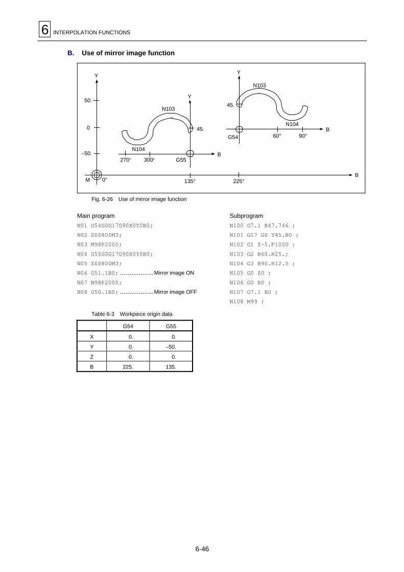
6 INTERPOLATION FUNCTIONS
6-46
B. Use of mirror image function
50.
N104
Y
Y
0
–50.
M 0°
N103
45.
270° 300° G55B
135° 225°
Y
G54
N103
N104B
60° 90°
B
45.
Fig. 6-26 Use of mirror image function
Main programN01 G54G0G17G90X0Y0B0;N02 Z0S800M3;N03 M98P2000;N04 G55G0G17G90X0Y0B0;N05 Z0S800M3;N06 G51.1B0; ..................Mirror image ON
N07 M98P2000;N08 G50.1B0; ..................Mirror image OFF
SubprogramN100 G7.1 B47.746 ;N101 G17 G0 Y45.B0 ;N102 G1 Z-5.F1000 ;N103 G2 B60.R25.;N104 G3 B90.R12.5 ;N105 G0 Z0 ;N106 G0 B0 ;N107 G7.1 B0 ;N108 M99 ;
Table 6-3 Workpiece origin data
G54 G55
X 0. 0.
Y 0. –50.
Z 0. 0.
B 225. 135.

INTERPOLATION FUNCTIONS 6
6-47
C. Use of circular interpolation commands
85.
Y
rN03
45°50
(mm)
47.5
10.
N04
N05
N06
r
50. 50.
90°100
135° 180°200
225°250
360°400 (mm)
270°300
r = (47.5 – 10)2 + 502
= 62.5 mmRadius of groove bottom = 63.662 mm
Fig. 6-27 Use of circular interpolation commands
N01 G90 G1 Y47.5 F1000 ;N02 G7.1 B63.662 ;N03 G17 G1 Y47.5 B45.;N04 G2 B90.R62.5 ;N05 G1 B180.;N06 G3 B270.I50.J37.5 ;
D. Operation examples with manual interruption
1. With “manual absolute” ON
Programmedcontour
Y
B
Cylindrical interpolationON
Manual interruption
N1N2 N3
N3’
N4
N4’
N5’
N6
N5Cylindrical interpolationOFF
N1 - N6: Programmed contourN2 - N4: In the mode of cylindrical interpolationN3: Manual interruptionN3 - N4: “Manual absolute” function ignored (N3’ and N4’)N5: “Manual absolute” function retrieved (N5’)
Fig. 6-28 With “manual absolute” ON

6 INTERPOLATION FUNCTIONS
6-48
2. With “manual absolute” OFF
Programmedcontour
Y
B
Cylindrical interpolationON
Manual interruption
N1N2 N3
N3’
N4
N4’
N5’
N6N5
Cylindrical interpolationOFF
N1 - N6: Programmed contourN2 - N4: In the mode of cylindrical interpolationN3: Manual interruptionN3 - N6: “Manual absolute” function OFF (N3’ to N6’)
N6’
Fig. 6-29 With “manual absolute” OFF
6. Related parameters
1. Set the type of the rotational axis (A or B) as “rotational” (with short-cut approach) in orderthat the initial angular movement should not occur on the roundabout route for a commandof tool diameter offset given in the vicinity of the 0° position.
N21 bit 0 = 0: Setting the type of the rotational axis as rotational= 1: Short-cut approach valid
2. Set the B- and A-axis as the primary parallel ones to the axis of abscissa and that of theordinate, respectively.
SU2 = 66: Setting the B-axis as parallel axis 1 for the axis of abscissaSU5 = 65: Setting the A-axis as parallel axis 1 for the axis of the ordinate
3. The following parameter setting is required for a cylindrical interpolation in the X-A plane onvertical machining centers:
F85 bit 7 = 1
4. The following parameter setting is required for inch data input in order that the speed of theangular movement may be calculated appropriately:
F85 bit 4 = 1
7. Related alarms
Table 6-4 Related alarms
AlarmNo. Alarm message Description Remedy
806 ILLEGALADDRESS
The address of argument in the block of selecting the cylin-drical interpolation does not refer to any rotational axis.
Use the correct address.
2110 ILLEGALFORMAT
The necessary conditions for the selection of cylindricalinterpolation are not yet all satisfied.
Refer to Table 6-1.
808 MIS-SET GCODE
An unavailable G-code is given in the mode of cylindricalinterpolation.
Refer to Table 6-2.
936 OPTION NOTFOUND (7, 0, 0)
The optional function for cylindrical interpolation is notprovided.
Equip the machine withthe option as required.

INTERPOLATION FUNCTIONS 6
6-49
6-12 Helical Interpolation: G02, G03
1. Function and purpose
Command G02 or G03 with a designation for the third axis allows synchronous circularinterpolation on the plane specified by plane-selection command G17, G18 or G19 with the linearinterpolation on the third axis.
2. Programming format
G17 G02 Xx1 Yy1 Zz1 Ii1 Jj1 Pp1 Ff1 ;
(G03)
or
G17 G02 Xx2 Yy2 Zz2 Rr2 Pp2 Ff2 ;
(G03)
3. Detailed description
θθsθe
Z
XX
Y
Y
l
1st
H734P0001
2ndp1-th
z1
1. For helical interpolation, movement designation is additionally required for one to two linearaxes not forming the plane for circular interpolation.
2. The velocity in the tangential direction must be designated as the feed rate F.
3. The pitch l is calculated as follows:
l =z1
(2π • p1 + θ)/2π
θ = θe – θs = tan–1 yexe
– tan–1 ysxs
(0 ≤ θ < 2π)
where (xs, ys): relative coordinates of starting point with respect to the arc center(xe, ye): relative coordinates of ending point with respect to the arc center
4. Address P can be omitted if the number of pitches is 1.
Feed rateNumber of pitchesArc center coordinatesLinear axis ending point coordinateArc ending point coordinates
Feed rateNumber of pitchesArc radiusLinear axis ending pointArc ending point coordinates

6 INTERPOLATION FUNCTIONS
6-50
5. Plane selectionAs with circular interpolation, the circular-interpolation plane for helical interpolation isdetermined by the plane-selection code and axis addresses. The basic programmingprocedure for helical interpolation is: selecting a circular-interpolation plane using a plane-selection command (G17, G18 or G19), and then designating the two axis addresses forcircular interpolation and the address of one axis (perpendicular to the circular-interpolationplane) for linear interpolation.
- X-Y plane circular, Z-axis linear
After setting G02 (or G03) and G17 (plane-selection command), set the axis addresses X,Y and Z.
- Z-X plane circular, Y-axis linear
After setting G02 (or G03) and G18 (plane-selection command), set the axis addresses Z,X and Y.
- Y-Z plane circular, X-axis linear
After setting G02 (or G03) and G19 (plane-selection command), set the axis addresses Y,Z and X.
4. Sample programs
Example 1:
G91 G28 X0 Y0 Z0;G92 X0 Z0 Y0;G17 G03 X100. Y50. Z-50. R50. F1000;
H734P0002
Startingpoint
Endingpoint
100.
–50.
50.
Y
Z
X
Example 2:
G91 G28 X0 Y0 Z0;G92 X0 Z0 Y0;G17 G03 X100. Y50. Z-50. R50. P2 F1000;
H734P0003
–50.
100.
50.
Y
Z
X
Startingpoint
Endingpoint
E

FEED FUNCTIONS 7
7-1
7 FEED FUNCTIONS
7-1 Rapid Traverse Rates
A separate rapid traverse rate can be set for each axis. The maximum rate of rapid traverse,however, is limited according to the particular machine specifications.Refer to the Operating manual for the machine for rapid traverse rates.Two types of tool paths are available for positioning: an interpolation type, which uses a line toperform interpolation from the starting point through the ending point, and a non-interpolationtype, which moves the tool at the maximum speed of each axis.Use a parameter to select the interpolation type or the non-interpolation type. The positioningtime is the same for both types.
7-2 Cutting Feed Rates
A cutting feed rate must be designated using address F and an eight-digit number (F8-digit directdesignation).The F8 digits must consist of five integral digits and three decimal digits, with the decimal point.Cutting feed rates become valid for commands G01, G02, G03, G33 and G34.
Example: Feed rateG01 X100. Y100. F200* 200.0 mm/minG01 X100. Y100. F123.4 123.4 mm/minG01 X100. Y100. F56.789 56.789 mm/min
* It means the same if F200. or F200.000 is set in stead of F200.
Note: An alarm (No. 713) will result if a feed rate command is not set for the first cuttingcommand (G01, G02, G03, G33 or G34) that is read firstly after power-on.
7-3 Asynchronous/Synchronous Feed: G94/G95
1. Function and purpose
Command G95 allows a feed rate per revolution to be set using an F-code.Command G94 retrieves the mode of asynchronous feed (per minuite).
2. Programming format
G94: Feed per minute (/min) [Asynchronous feed]G95: Feed per revolution (/rev) [Synchronous feed]
Since command G95 is modal, it will remain valid until command G94 is issued.

7 FEED FUNCTIONS
7-2
3. Detailed description
1. Feed rates that can be set using F-codes are listed in the table below.The table below also lists synchronous feed rates, which are to be set in millimeters (orinches) per spindle revolution using F-codes.
G94F_ (Feed per minute) G95F_ (Feed per revolution)
Input in mm 1 to 240000 mm/min (F1 to F240000) 0.0001 to 500.0000 mm/rev (F1 to F5000000)
Input in inches 0.01 to 9600.00 in./min (F1 to F960000) 0.000001 to 9.999999 in./rev (F1 to F9999999)
2. The effective feed rate per revolution, that is, the actual moving speed of the machine, canbe calculated as follows:
FC = F × N × OVR (Expression 1)
where FC: Effective feed rate (mm/min or inches/min)F: Designated feed rate (mm/rev or inches/rev)N: Spindle speed (rpm)OVR: Cutting feed override
If multiple axes are selected at the same time, effective feed rate FC given by expression 1above will become valid for the corresponding vectorial direction.
4. Remarks
1. On the POSITION display, FEED denotes an effective feed rate that is expressed in a feedrate per minute (mm/min or inches/min), based on the selected feed rate, the spindle speed,and the cutting feed override.
2. If the effective feed rate should become larger than the cutting feed limit speed, that limitspeed will govern.
3. In the dry run mode, feed will become asynchronous and the machine will operate at anexternally preset feed rate (mm/min or inches/min).
4. According to the setting of bit 1 of parameter F93, synchronous or asynchronous feed mode(G95 or G94) is automatically made valid upon power-on or by execution of M02 or M30.

FEED FUNCTIONS 7
7-3
7-4 Selecting a Feed Rate and Effects on Each Control Axis
As mentioned earlier, the machine has various control axes. These control axes can be broadlydivided into linear axes, which control linear motions, and rotational axes, which control rotationalmotions. Feed rates for control axes have different effects on the tool speed, which is of greatimportance for machining quality, according to the particular type of axis controlled.The amount of displacement must be designated for each axis, whereas the feed rate is to bedesignated as a single value for the intended tool movement. Before letting the machine controltwo or more axes at the same time, therefore, you must understand how the feed rate designatedwill act on each axis. In terms of this, selection of a feed rate is described below.
1. Controlling linear axes
The feed rate that has been selected using an F-code acts as a linear velocity in the movingdirection of the tool, irrespective of whether only one axis is to be controlled or multiple axessimultaneously.
Example: If linear axes (X- and Y-axes) are to be controlled using a feed rate of f:
MEP038
“f” denotes thevelocity in thisdirection.
Y
X
y
x
P2 (Tool ending point)
P1 (Tool starting point)
When only linear axes are to be controlled, setting of a cutting feed rate itself is only required.The feed rate for each axis refers to that component of the specified feed rate which correspondswith the ratio of movement stroke on the respective axis to the actual movement distance.
In the example shown above:x
X-axis feed rate = f ×x2 + y2
yY-axis feed rate = f ×
x2 + y2
2. Controlling a rotational axis
When a rotational axis is to be controlled, the selected feed rate acts as the rotating speed of therotational axis, that is, as an angular velocity.Thus, the cutting speed in the moving direction of the tool, that is, a linear velocity variesaccording to the distance from the rotational center to the tool. This distance must be consideredwhen setting a feed rate in the program.

7 FEED FUNCTIONS
7-4
Example 1: If a rotational axis (C-axis) is to be controlled using a feed rate of f (deg/min):
The linear velocity is obtainable from π!r!f180
“f” denotes the angular velocity.
P2 (Tool ending point)
Center ofrotation
P1 (Tool ending point)
MEP034
c
r
In this case, the cutting speed in the moving direction of the tool (linear velocity) “fc” is calculatedby:
fc = f × π • r180
Hence, the feed rate to be programmed for the required value fc is:
f = fc × 180π • r
Note: If the tool is to be moved by controlling linear axes along the circumference using thecircular interpolation function, the feed rate programmed is the velocity acting in themoving direction of the tool, that is, in the tangential direction.
Example 2: If linear axes (X- and Y-axes) are to be controlled at a feed rate of f using thecircular interpolation function:
Y
Xi
MEP040
“f” denotes thislinear speed.
x
P1
P2y
In this case, the X- and Y-axis feed rates will change with the movement of the tool. The resultantvelocity, however, will be kept at the constant value, f.

FEED FUNCTIONS 7
7-5
3. Controlling a linear axis and a rotational axis at the same time
The NC unit controls linear axes and rotational axes in exactly the same manner.For control of rotational axes, data given as a coordinate word (with A, B or C) is handled as anangle, and data given as a feed rate (F) is handled as a linear velocity. In other words, an angleof one degree for a rotational axis is handled as equivalent to a moving distance of 1 mm for alinear axis. Thus, for simultaneous control of a linear axis and a rotational axis, the magnitudes ofthe individual axis components of the data that has been given by F are the same as thoseexisting during linear axis control described previously in Subparagraph 1. above. In this case,however, the velocity components during linear axis control remain constant in both magnitudeand direction, whereas those of rotational axis control change in direction according to themovement of the tool. Therefore, the resulting feed rate in the moving direction of the toolchanges as the tool moves.
Example: If a linear axis (X-axis) and a rotational axis (C-axis) are to be controlled at the sametime at a feed rate of f:
MEP036
c
fc
ft
fxP1
θ
θx
fc ft
P2 fx
r
Center of rotation
- “fx” is constant in both sizeand direction.
- “fc” is constant in size, butvaries in direction.
- “ft” varies in both size anddirection.
X-axis incremental command data is expressed here as x, and that of C-axis as c.The X-axis feed rate (linear velocity), fx, and the C-axis feed rate (angular velocity), ω, can becalculated as follows:
fx = f ×x2 + c2
x !!!!!!! [1] ω = f ×
x2 + c2
c!!!!!!! [2]
The linear velocity “fc” that relates to C-axis control is expressed as:
fc = ω • π • r180 !!!!!!! [3]
If the velocity in the moving direction of the tool at starting point P1 is taken as “ft”, and its X- andY-axis components as “ftx” and “fty” respectively, then one can express “ftx” and “fty” as follows:
ftx = –r sin ( π180 θ) × π
180 ω + fx !!!!!!! [4]
fty = –r cos ( π180 θ) × π
180 ω !!!!!!! [5]
where r denotes the distance (in millimeters) from the rotational center to the tool, and q denotesthe angle (in degrees) of starting point P1 to the X-axis at the rotational center.

7 FEED FUNCTIONS
7-6
From expressions [1] through [5] above, the resultant velocity “ft” is:
ft = ftx2 + fty2
= f ×
π180
π90
π • r • c180
x2 – x • c • r sin ( θ) + ( )2
x2 + c2 !!!!!!! [6]
The feed rate f that is to be set in the program must be therefore:
f = ft × π
180π90
π • r • c180
x2 – x • c • r sin ( θ) + ( )2
x2 + c2
!!!!!!! [7]
In expression [6], “ft” is the velocity at starting point P1 and thus the value of ft changes with thatof θ which changes according to the rotational angle of the C-axis. To keep cutting speed “ft” asconstant as possible, the rotational angle of the C-axis in one block must be minimized to ensurea minimum rate of change of θ.
7-5 Automatic Acceleration/Deceleration
The rapid traverse and manual feed acceleration/deceleration pattern is linear acceleration andlinear deceleration. Time constant TR can be set independently for each axis using parameters in1 msec steps within a range from 1 to 500 msec. The cutting feed (not manual feed) accele-ration/deceleration pattern is exponential acceleration/deceleration. Time constant TC can be setindependently for each axis using parameters in 1 msec steps within a range from 1 to 500 msec.(Normally, the same time constant is set for each axis.)
TEP037
Rapid feed acceleration/deceleration pattern(TR = Rapid feed time constant)(Td = Deceleration check time)
Cutting feed acceleration/deceleration pattern(Tc = Cutting feed time constant)
TR TR
Td
t
fContinuouscommand
Continuouscommand
Tc Tc
t
f
During rapid traverse and manual feed, the following block is executed after the command pulseof the current block has become “0” and the tracking error of the acceleration/deceleration circuithas become “0”. During cutting feed, the following block is executed as soon as the commandpulse of the current block becomes “0” and also the following block can be executed when anexternal signal (error detection) can detect that the tracking error of the acceleration/decelerationcircuit has reached “0”. When the in-position check has been made valid (selected by machineparameter) during the deceleration check, it is first confirmed that the tracking error of theacceleration/deceleration circuit has reached “0”, then it is checked that the position deviation isless than the parameter setting, and finally the following block is executed.

FEED FUNCTIONS 7
7-7
7-6 Speed Clamp
This function exercises control over the actual cutting feed rate in which override has beenapplied to the cutting feed rate command so that the speed clamp value preset independently foreach axis is not exceeded.
Note: Speed clamping is not applied to synchronous feed.
7-7 Exact-Stop Check: G09
1. Function and purpose
Only after the in-position status has been checked following machine deceleration and stop orafter deceleration checking time has been passed, may you want to start the next blockcommand in order to reduce possible machine shocks due to abrupt changes in tool feed rateand to minimize any rounding of workpieces during corner cutting. An exact-stop check functionis provided for these purposes.
2. Programming format
G09 G01 (G02, G03) ;
Exact-stop check command G09 is valid only for the cutting command code (G01, G02, or G03)that has been set in that block.
3. Sample program
N001 G09 G01 X100.000 F150; The next block is executed after an in-position statuscheck following machine deceleration and stop.
N002 Y100.000 ;
TEP038
N002
The solid line indicates a feedrate pattern with the G09 available.The dotted line indicates a feedrate pattern without the G09.
N001
(Selected feedrate)f
Y-axis
X-axisTool
With G09available
Without G09
N001
N002Time
Fig. 7-1 Validity of exact-stop check

7 FEED FUNCTIONS
7-8
4. Detailed description
A. Continuous cutting feed commands
TEP039
Ts
Preceding block Next block
Fig. 7-2 Continuous cutting feed commands
B. Cutting feed commands with in-position status check
TEP040
Ts Ts
Lc
Preceding block Next block
Fig. 7-3 Block-to-block connection in cutting feed in-position status check mode
In Fig. 7-2 and 7-3 above,
Ts: Cutting feed acceleration/deceleration time constantLc: In-position width
As shown in Fig. 7-3, in-position width Lc represents the remaining distance within the blockimmediately preceding the next block to be executed.
The in-position width helps keep anyrounding of workpieces during cornercutting within a fixed level.
If rounding of workpieces at corners is tobe completely suppressed, include dwellcommand G04 between cutting blocks.
TEP041
Preceding block
Next blockLc

FEED FUNCTIONS 7
7-9
C. With deceleration check
- With linear acceleration/deceleration
TEP042
Ts : Acceliration/deceleration time constantTd : Deceleration check time
Td = Ts + (0 to 14 ms)
Preceding block Next block
Ts
Td
- With exponential acceleration/deceleration
TEP043
Ts : Acceleration/deceleration timeconstant
Td : Deceleration check timeTd = 2 × Ts + (0 to 14 ms)
Ts
Td
Preceding block Next block
- With exponential acceleration/linear deceleration
TEP044
Ts : Acceleration/deceleration timeconstant
Td : Deceleration check timeTd = 2 × Ts + (0 to 14 ms)
Preceding block Next block
2 × Ts
Td Ts
The time required for the deceleration check during cutting feed is the longest among the cuttingfeed deceleration check times of each axis determined by the cutting feed accele-ration/deceleration time constants and by the cutting feed acceleration/ deceleration mode of theaxes commanded simultaneously.

7 FEED FUNCTIONS
7-10
7-8 Exact-Stop Check Mode: G61
1. Function and purpose
Unlike exact-stop check command G09 which performs an in-position status check on that blockonly, command G61 functions as a modal command. That is, this command acts on all itssucceeding cutting commands (G01, G02, and G03) so that deceleration occurs at the end ofeach block, followed by an in-position status check. Command G61 is cleared by geometrycompensation command G61.1, automatic corner override command G62, tapping modecommand G63, or cutting mode command G64.
2. Programming format
G61;
7-9 Automatic Corner Override: G62
1. Function and purpose
Command G62 automatically overrides in the tool-diameter offset mode the selected feed rate toreduce the tool load during inner-corner cutting or automatic inner-corner rounding.Once command G62 has been issued, the automatic corner override function will remain validuntil it is cancelled by tool-diameter offsetting cancellation command G40, exact-stop checkmode command G61, geometry compensation command G61.1, tapping mode command G63,or cutting mode command G64.
2. Programming format
G62;
3. Detailed description
A. Inner-corner cutting
When inner corner of a workpiece is cut as shown in the figure below, the load on the toolincreases because of large amount of cutting. Using G62 in such a case allows the cutting feedrate to be automatically overriden within the preset zone, and thus the tool load to be reduced toaccomplish appropriate cutting.This function, however, is valid only for programming the as-finished shape of a workpiece.
MEP046
θ
Ci
[1] [2][3]
θ : Inner-corner maximum angleCi : Deceleration zone (IN)
Tool center path
Cutting amount
WorkpieceWorkpiece surface shape
Programmed path(Finish shape)
Tool
Cuttingamount
S
Fig. 7-4 Inner-corner cutting

FEED FUNCTIONS 7
7-11
<Machine operation>
- When the automatic corner override function is not used:In the figure above, as the tool is moving in order of positions [1]→[2]→[3], the load on the toolincreases because the cutting amount at position [3] is larger than that of position [2] by thearea of hatched section S.
- When the automatic corner override function is used:In the figure above, if maximum angle q of the inner corners is smaller than that preset in theappropriate parameter, the feed rate is automatically overriden with the preset value formovement through deceleration zone Ci.
<Setting parameters>
Set the following parameters as user parameters:
- F29: Override 0 to 100 (%)
- F21: Inner-corner maximum angle θ 0 to 180 (deg)
- F22: Deceleration zone Ci data 0 to 99999.999 (mm) or to 3937.000 (inches)
For further details of parameter setting, refer to the description in the Operating manual and theParameter list.
B. Automatic corner rounding
TEP046
Workpiece
Programmed path Tool center path
Corner rounding center
Cutting amount
CiCorner rounding section
Workpiecesurface shape
<Operation>
For inner corner cutting with automatic corner rounding, override will be effected as set inparameter through the deceleration zone Ci and corner rounding section (No check made aboutangle).

7 FEED FUNCTIONS
7-12
4. Operation examples
- Line-to-line corner
MEP047
θ
Ci
Programmed path
Tool center path
Tool
The feed rate is automatically overridden with the preset value by the parameter F29 throughdeceleration zone Ci.
- Line-to-circular (outside offsetting) corner
MEP048
θ
Ci
Tool centerpath
Programmedpath
Tool
The feed rate is automatically overridden with the preset value by the parameter F29 throughdeceleration zone Ci.
- Arc(internal compensation)-to-line corner
MEP049
θ
Ci
Programmed path
Tool center path
Tool
Tool
The feed rate is automatically overridden with the preset value by the parameter F29 throughdeceleration zone Ci.
Note: Data of deceleration zone Ci at which automatic overriding occurs represents thelength of the arc for a circular interpolation command.

FEED FUNCTIONS 7
7-13
- Arc(internal compensation)-to-arc (external compensation) corner
N1N2
θ
Ci
Programmed path
Tool center path
MEP050
The feed rate is automatically overridden with the preset value by the parameter F29 throughdeceleration zone Ci.
5. Correlationships to other command functions
Function Override at corners
Cutting feedrate override Automatic corner override is applied after cutting feed override.
Override cancel Automatic corner override is not cancelled by override cancel.
Feed rate clamp Valid (for the feed rate after automatic corner override)
Dry run Automatic corner override is invalid.
Synchronous feed A synchronous feed rate is automatically corner-overridden.
Skip (G31) During tool-diameter offset, G31 will result in a program error.
Machine lock Valid
G00 Invalid
G01 Valid
G02, G03 Valid
6. Precautions
1. Automatic corner override is valid only during the G01, G02 or G03 modes; it is invalidduring the G00 mode. Also, when the command mode is changed over from G00 to G01,G02, or G03 (or vice versa) at a corner, automatic corner override is not performed on theG00-containing block at that corner.
2. Even in the automatic corner override mode, automatic corner override is not performeduntil the tool diameter compensation mode has been set.

7 FEED FUNCTIONS
7-14
3. Automatic corner override does not occur at corners where tool diameter compensation is tostart or to be cancelled.
TEP051
Startup block
Tool center path
Cancel block
Automatic corner override remains invalid.
Programmed path
4. Automatic corner override does not occur at corners where tool diameter compensation I, Jand K vector commands are to be executed.
TEP052
(G41X_Y_I_J_;)
Programmed path
Tool center path
Automatic corner override remains invalid.
Block including I and Jvector commands
5. Automatic corner override occurs only when crossing points can be calculated. Crossingpoints can not be calculated in the following case:
- Four or more blocks that do not include move command appear in succession.
6. For circular interpolation, the deceleration zone is represented as the length of the arc.
7. The parameter-set angle of an inner corner is applied to the angle existing on theprogrammed path.
8. Setting the maximum angle to 0 or 180 degrees in the angle parameter results in anautomatic corner override failure.
9. Setting the override to 0 or 100 in the override parameter results in an automatic corneroverride failure.

FEED FUNCTIONS 7
7-15
7-10 Tapping Mode: G63
1. Function and purpose
Command G63 enters the NC unit into a control mode suitable for tapping. This mode has thefollowing features:- The cutting feed override is fixed at 100%.- Commands for deceleration at block-to-block connections are invalidated.- The feed hold function is invalidated.- The single-block function is invalidated.- Tapping-mode signal is output.The G63 command mode will remain valid until it is cancelled by exact-stop check modecommand G61, geometry compensation command G61.1, automatic corner override commandG62 or cutting mode command G64.
2. Programming format
G63 ;
7-11 Cutting Mode: G64
1. Function and purpose
Command G64 enters the NC unit into a control mode proper to obtain smoothly cut surfaces.Unlike the exact-stop check mode (G61 command mode), the cutting mode allows the next blockto be executed without decelerating/stopping the machine between cutting feed blocks.The G64 command mode is cleared by exact-stop check mode command G61, geometrycompensation command G61.1, automatic corner override command G62 or tapping modecommand G63.In the initial state of the NC unit, the cutting mode is selected.
2. Programming format
G64 ;

7 FEED FUNCTIONS
7-16
7-12 Geometry Compensation/Accuracy Coefficient: G61.1/,K
7-12-1 Geometry compensation function: G61.1
1. Function and purpose
The geometry compensation function (G61.1) is provided to reduce conventional geometryerrors caused by delayed follow-up of smoothing circuits and servo systems.The geometry compensation function is canceled, or replaced, by the functions of exact stopcheck mode (G61), automatic corner override (G62), tapping mode (G63) and cutting mode(G64).
The geometry compensation function is composed of the following four functions:
1. Pre-interpolation acceleration/deceleration2. Feed forward control3. Optimum corner deceleration4. Precise vector compensation
Refer to Section 11-2 “Geometry Compensation Function” in Chapter 3 of the Operating Manualfor the description of the above functions.
2. Programming format
G61.1;
3. Sample program
N001 G61.1G01X100.F1000X100.Y–100.X–100.Y–100.X–100.X–100.Y100.X100.Y100.G64
Selection of the geometry compensation function
Cancellation of the geometry compensation function
4. Remarks
1. The geometry compensation function cannot be selected or canceled for EIA/ISO programsby the setting of the parameter F72 (which is only effective for MAZATROL programs).
2. The geometry compensation is an optional function. On machines without correspondingoption the code G61.1 can only lead to an alarm (808 MIS-SET G CODE).
3. The geometry compensation function is suspended during execution of the followingoperations:Rapid traverse of non-interpolation type (according to bit 6 of parameter F91), Synchronoustapping, Measurement (skipping), Threading.
4. The pre-interpolation acceleration/deceleration is effective from the block of G61.1 onward.

FEED FUNCTIONS 7
7-17
7-12-2 Accuracy coefficient (,K)
1. Function and purpose
In the mode of geometry compensation (G61.1) the feed of the tool is automatically deceleratedat relevant corners and for circular motions by the optimal corner deceleration and the circularfeed limitation, respectively, in order to enhance the machining accuracy. Specifying an accuracycoefficient in the machining program can further improve the accuracy by additionallydecelerating the feed for the sections concerned.
2. Programming format
,K_; Specify the rate of reduction of the corner deceleration speed and the circular feed ratelimitation in percentage terms.
The accuracy coefficient is canceled in the following cases:- Resetting is performed,- The geometry compensation function is canceled (by G64),- A command of “,K0” is given.
3. Sample program
<Example 1>
N001 G61.1N200 G1X_Y_,K30N300 X_Y_N400 …
The rate of feed for a corner deceleration or circular motion in the section fromthis block onward will be reduced to 70% of the value applied in default of theaccuracy coefficient command.
<Example 2>
N001 G61.1N200 G2I-10.,K30N300 G1X10.,K0N400 …
Deceleration to 70% occurs for this block only.
The accuracy coefficient is canceled from this block onward.
4. Remarks
1. The accuracy coefficient cannot be specified in a MAZATROL program.
2. Specifying an accuracy coefficient 1 to 99 at address “,K” increases the machining timeaccording to the additional deceleration at relevant corners and for circular motions.

7 FEED FUNCTIONS
7-18
7-13 Inverse Time Feed: G93 (Option)
1. Function and purpose
When tool-diameter offsetting is performed for a smooth linear or circular small-line-segmentcommand, differences will occur between the shape defined in the program and that existingafter tool-diameter offsetting. The feed commands with G94 and G95 only apply for the toolpath existing after offsetting, and the tool speed at the point of cutting (that is, along the shapedefined in the program), therefore, will not be kept constant so that the resulting speedfluctuations will cause seams on the surface machined.Setting of an Inverse Time Feed command code makes constant the processing time for thecorresponding block of the machining program, and thus provides control to ensure a constantmachining feed rate at the point of cutting (along the programmed shape).Setting of command code G93 specifies the inverse time assignment mode.In G93 mode, the reciprocal of the machining time for the block of cutting command code G01,G02 or G03 is to be assigned using an F-code. Data that can be assigned with address F is from0.001 to 99999.999.
The feed rate for the corresponding block is calculated (by NC) from the commanded length ofthe program block and the value of the F-code.
- For linear interpolation (G01)
[Speed] : mm/min (for metric system) orinches/min (for inch system)
[Distance] : mm (for metric system) orinches (for inch system)
- For circular interpolation (G02 or G03)
[Speed] : mm/min (for metric system) orinches/min (for inch system)
[Arc radius] : mm (for metric system) orinches (for inch system)
2. Programming formats
- Linear interpolation: G93 G01 Xx1 Yy1 Ff1- Circular interpolation: G93 G02 Xx1 Yy1 Rr1 Ff1
(Code G03 can be used, instead of G02, and code I, J and/or K instead of R.)
3. Precautions
- Code G93, which belongs to the same G-code group as that of G94 (feed per minute) and G95(feed per revolution), is a modal G-code.
- In G93 mode, since F codes are not handled as modal codes, they must be set for each block.The absence of F-code results in alarm 816 FEEDRATE ZERO.
- Setting of F0 during G93 mode results in alarm 816 FEEDRATE ZERO.
- For a corner insertion block during tool-diameter offsetting, the F-code value in the previousblock is regarded as the inverse time command value.
- A modal F-code must be set if the G93 mode is changed over to G94 or G95.
[Speed]F-code value =
[Distance]
[Speed]F-code value =
[Arc radius]

FEED FUNCTIONS 7
7-19
4. Description of alarms
No. Message Description
940 NO INVERSE TIME OPTION The Inverse Time Feed option is not present.
941 G93 MODE An illegal G-code* has been set during G93 mode.
* Illegal G-codes are:G31 Skip
G32, G33 Threading
G7", G8", G2"" Fixed cycle
5. Sample program
N01 G90 G00 X-80. Y80.N02 G01 G41 X0 Y0 D11 F500N03 X200.N04 G93 G02 Y-200.R100. F5N05 G03 Y-400.R100. F5N06 G02 Y-600.R100. F5N07 G94 G01 X0 F500N08 Y0N09 G40 X-80. Y80.N10 M02
MEP053
Y
X
200
200φ
200φ
200φ
–200
–400
–600
D11 = 10 mm
D11 = 20 mm
In this example, set data as follows if the machining speed in the circular-interpolation blocks isto be made equal to 500 mm/min that is specified for the linear-interpolation block of G01:
[Speed] 500F-code value =
[Arc radius]=
100

7 FEED FUNCTIONS
7-20
- NOTE -
E

DWELL FUNCTIONS 8
8-1
8 DWELL FUNCTIONSThe start of execution of the next block can be delayed using a G04 command.
8-1 Dwell Command in Time: (G94) G04
1. Function and purpose
Setting command G04 in the feed-per-second mode (command G94) delays the start ofexecution of the next block for the specified time.
2. Programming format
G94 G04 X_;orG94 G04 P_;
Data must be set in 0.001 seconds.For address P, the decimal point is not available. Setting a decimal point will cause an alarm.
3. Detailed description
1. The setting range for dwell time is as follows:
Unit of data setting Range for address X Range for address P
0.001 mm, 0.0001 inches 0.001 to 99999.999 (sec) 1 to 99999999 (× 0.001 sec)
2. The count for the dwell command which is preceded by a block with cutting-feed commandis not started until the movement of the preceding block has been brought to a completestop.
TEP053
Cutting command inthe preceding block
Dwell command
Dwell time
Next block
If the dwell command is given in one block together with an M-, S- T- or B-code, the dwellcount and the execution of the respective code will be started at the same time.
3. If the bit 2 of parameter F92 is set to 1, dwell command value is always processed in timespecification irrespective of G94 and G95 modes.
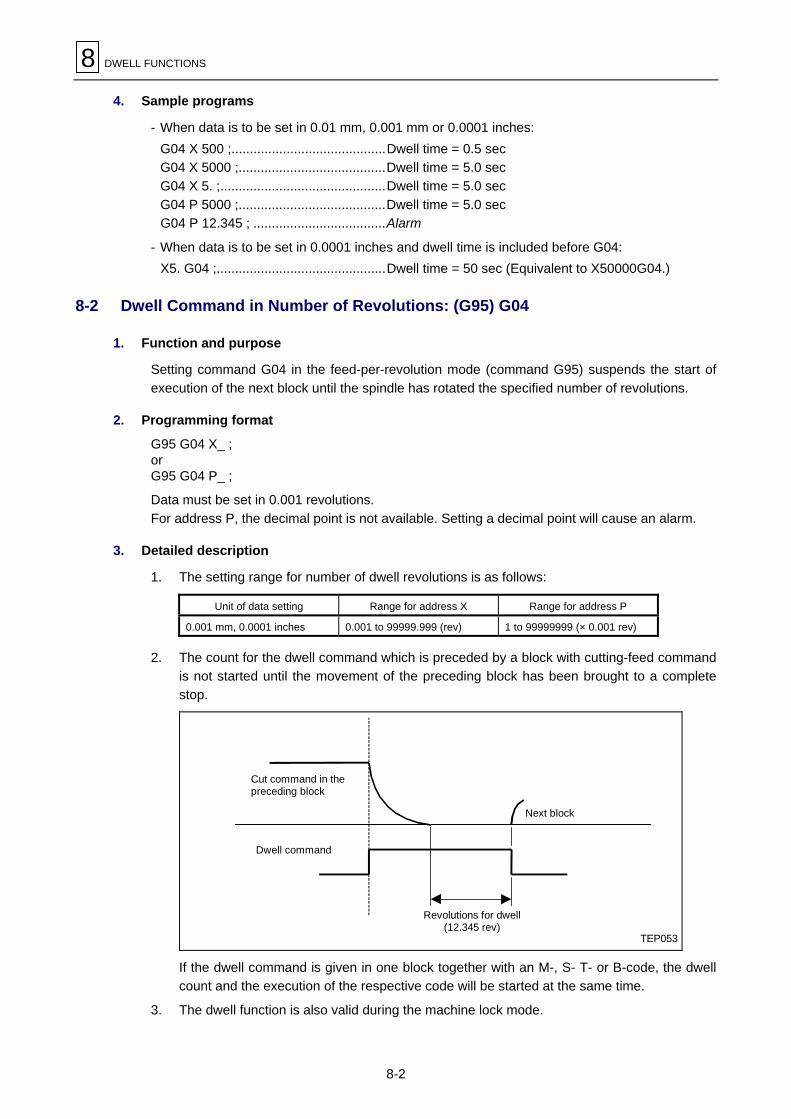
8 DWELL FUNCTIONS
8-2
4. Sample programs
- When data is to be set in 0.01 mm, 0.001 mm or 0.0001 inches:G04 X 500 ;..........................................Dwell time = 0.5 secG04 X 5000 ;........................................Dwell time = 5.0 secG04 X 5. ;.............................................Dwell time = 5.0 secG04 P 5000 ;........................................Dwell time = 5.0 secG04 P 12.345 ; ....................................Alarm
- When data is to be set in 0.0001 inches and dwell time is included before G04:X5. G04 ;..............................................Dwell time = 50 sec (Equivalent to X50000G04.)
8-2 Dwell Command in Number of Revolutions: (G95) G04
1. Function and purpose
Setting command G04 in the feed-per-revolution mode (command G95) suspends the start ofexecution of the next block until the spindle has rotated the specified number of revolutions.
2. Programming format
G95 G04 X_ ;orG95 G04 P_ ;
Data must be set in 0.001 revolutions.For address P, the decimal point is not available. Setting a decimal point will cause an alarm.
3. Detailed description
1. The setting range for number of dwell revolutions is as follows:
Unit of data setting Range for address X Range for address P
0.001 mm, 0.0001 inches 0.001 to 99999.999 (rev) 1 to 99999999 (× 0.001 rev)
2. The count for the dwell command which is preceded by a block with cutting-feed commandis not started until the movement of the preceding block has been brought to a completestop.
TEP053
Dwell command
Cut command in thepreceding block
Revolutions for dwell(12.345 rev)
Next block
If the dwell command is given in one block together with an M-, S- T- or B-code, the dwellcount and the execution of the respective code will be started at the same time.
3. The dwell function is also valid during the machine lock mode.

DWELL FUNCTIONS 8
8-3
4. During rest of the spindle, dwell count is also halted. When the spindle restarts rotating,dwell count will also restart.
5. If the bit 2 of parameter F92 is set to 1, dwell command value is alway processed in timespecification.

8 DWELL FUNCTIONS
8-4
- NOTE -
E

MISCELLANEOUS FUNCTIONS 9
9-1
9 MISCELLANEOUS FUNCTIONS
9-1 Miscellaneous Functions (M3-Digit)
Miscellaneous functions, which are also referred to as M-code functions, give spindle forward/backward rotation and stop commands, coolant on/off commands, and other auxiliary commandsto the NC machine.For the NC unit, these functions must be selected using M3-digit data (three-digit data precededby address M). Up to four sets of M3-digit data can be included in one block.
Example: G00 Xx1 Mm1 Mm2 Mm3 Mm4;
If five or more sets of M3-digit data are set, only the last four sets will become valid.Refer to the machine specification for more specific relationships between available data andfunctions.For M-codes M00, M01, M02, M30, M98, M99, M998 and M999, the next block of data is notread into the input buffer since pre-reading is disabled automatically.The M-codes can be included in any block that contains other command codes. If, however, theM-codes are included in a block that contains move commands, then the execution priority willbe either
- the M-code functions are executed after completion of movement, or- the M-code functions are executed together with movement.
It depends on the machine specifications which type of processing is applied.Processing and completion sequences are required in each case for all M commands exceptM98 and M99.The following lists six types of special M-code functions:
1. Program Stop: M00When this M-code is read, the tape reader will stop reading subsequent block. Whether themachine function such as spindle rotation and coolant will also stop depends on themachine specifications. The machine operation is restarted by pressing the cycle startbutton on the operation panel. Whether resetting can be initiated by M00 or not alsodepends on the machine specifications.
2. Optional Stop: M01When the M01 code is read with the [OPTIONAL STOP] menu function set to ON, the tapereader will stop operating to perform the same function as M00.The M01 command will be ignored if the [OPTIONAL STOP] menu function is set to OFF.
Example: MN10 G00 X1000;N11 M01;N12 G01 X2000 Z3000 F600; M
<[OPTIONAL STOP] menu function status and operation>If the menu function is on, operation stops at N11.If the menu function is off, operation does not stop at N11 and N12 is executed.
3. Program End: M02 or M30Usually, the program end command is given in the final block of machining program. Usethis command mainly for reading data back to the head of the program during memoryoperation, or rewinding the tape in the tape operation mode (use an M30 command torewind the tape). The NC unit is automatically reset after tape rewinding and execution ofother command codes included in that block.
9 MISCELLANEOUS FUNCTIONS
9-2
Automatic resetting by this command cancels both modal commands and offsetting data,but the designated-position display counter is not cleared to zero.The NC unit will stop operating when tape rewinding is completed (the automatic run modelamp goes out). To restart the NC unit, the cycle start button must be pressed.Beware that if, during the restart of the NC unit following completion of M02 or M30execution, the first movement command has been set in a coordinate word only, the validmode will be the interpolation mode existing when the program ended. It is recommended,therefore, that the first movement command be given with an appropriate G-code.
4. Subprogram Call/End: M98, M99Use M98 or M99 to branch the control into a subprogram or to recall it back to the callingprogram.As M99 and M99 are internaly processed by the NC M-code signals ans strobe signals arenot output.
<Internal processing by the NC unit when M00, M01, M02 or M30 is used>After M00, M01, M02 or M30 has been read, data pre-reading is automatically aborted. Othertape rewinding operations and the initialization of modals by resetting differ according to themachine specification.
Note 1: M00, M01, M02 and M30 output independent signals, which will be cancelled bypressing the RESET key.
Note 2: Tape rewinding is performed only when the tape reader has a rewinding function.
9-2 No. 2 Miscellaneous Functions (A8/B8/C8-Digit)
The No. 2 miscellaneous functions are used for positioning an index table. For the NC unit, thesefunctions must be designated using an eight-digit value (form 0 to 99999999) preceded byaddress A, B or C.The output signals are BCD signals of command data and start signals.A, B or C codes can be included in any block that contains other command codes. If, however,the A, B or C codes can be included in a block that contains move commands, then the executionpriority will be either
- the A, B or C code functions are performed after completion of movement, or
- the A, B or C code functions are performed together with movement.
It depends on the machine specifications which type of processing is applied.Processing and completion sequences are required in each case for all No. 2 miscellaneousfunctions.
Address combinations are shown below. The same address for both additional axis and the No.2 miscellaneous functions cannot be used.
Additional axis
No. 2 miscellaneous functionsA B C
A × ! !
B ! × ○
C ! ! ×
Note: When A has been designated as the No. 2 miscellaneous function address, linearangle commands cannot be used.
E

SPINDLE FUNCTIONS 10
10-1
10 SPINDLE FUNCTIONS
10-1 Spindle Function (S5-Digit Analog)
When the S5-digit function is added, this function must be set using the numerical command offive digits preceding an S code (0 to 99999) and for other case, two digits preceding by an Scode is used.S command binary outputs must be selected at this time.By designating a 5-digit number following the S code, this function enables the appropriate gearsignals, voltages corresponding to the commanded spindle speed (rpm) and start signals to beoutput.Processing and completion sequences are required for all S commands.The analog signal specifications are given below.
- Output voltage ......................................................... 0 to 10V or –8 to +8V
- Resolution................................................................ 1/4096 (2 to the power of –12)
- Load conditions ....................................................... 10 kiloohms
- Output impedance ................................................... 220 ohms
If the parameters for up to 4 gear range steps are set in advance, the gear range correspondingto the S command will be selected by the NC unit and the gear signal will be output. The analogvoltage is calculated in accordance with the input gear signal.
- Parameters corresponding to individual gears... Limit speed, maximum speed, gear shiftspeed and maximum speed during tapping.
- Parameters corresponding to all gears .............. Orient speed, minimum speed
10-2 Spindle Clamp Speed Setting: G92
1. Function and purpose
The code G92 can be used to set the maximum and minimum spindle speeds at addresses Sand Q, respectively.
2. Programming format
G92 Ss Qq Rr;
s: Maximum spindle speedq: Minimum spindle speedr: Spindle for speed clamping (to be specified with 3 for the milling spindle)
3. Detailed description
For gear change between the spindle and spindle motor, four steps of gear range can be set bythe related parameters in steps of 1 min–1 (rpm). In range defined by two ways, parameter settingand G92 SsQq setting, the smaller data will be used for the upper limit and the larger data for thelower limit.Do not fail to designate the spindle with argument “R3” in the G92 command block.

10 SPINDLE FUNCTIONS
10-2
- NOTE -
E

TOOL FUNCTIONS 11
11-1
11 TOOL FUNCTIONS
11-1 Tool Function (4-Digit T-Code)
Tool function, also referred to as T-code function, is used to designate the tool number and offsetnumber. Of a four-digit integer at address T, upper and lower two digits are respectively used tospecify the tool number and offset number.
Only one T-code can be included in a block, and the available range of T-codes depends on themachine specifications. For further details, especially on how to number the actual tools to beused, refer to the operating manual of the relevant machine.
The T-code can be given with any other commands in one block, and the T-code given togetherwith an axis motion command is executed, depending upon the machine specifications, in one ofthe following two timings:
- The T-code is not executed till completion of the motion command, or- The T-code is executed simultaneously with the motion command.
11-2 Tool Function (8-Digit T-Code)
This function allows you to select a tool number (from 0 to 99999999) using eight-digit commanddata preceded by address T. Only one T-code can be included in a block.
Set bit 4 of parameter F94 to 0 to select the group-number designation for T-code funciton, or setthis bit to 1 to select the tool-number designation.

11 TOOL FUNCTIONS
11-2
- NOTE -
E

TOOL OFFSET FUNCTIONS 12
12-1
12 TOOL OFFSET FUNCTIONS
12-1 Tool Offset
1. Overview
As shown in the diagram below, three types of basic tool offset functions are available: toolposition offset, tool length offset, and tool diameter offset.These three types of offset functions use offset numbers for designation of offset amount. Set theamount of offset directly using the operation panel or by applying the function of programmedparameter input. MAZATROL tool data can also be used for tool length offset or tool diameteroffset operations according to the parameter setting.
MEP055
L1
rrL2
L2+2r (Double extension) L1–r
Tool length offset
Reference point
Tool length
Plan
Side view
Tool diameter offset
Tool position offset
Offset tothe right
Offset to the left
Plan
(Contraction)

12 TOOL OFFSET FUNCTIONS
12-2
2. Selecting the amounts of tool offset
The amounts of tool offset corresponding to the offset numbers must be prestored on the TOOLOFFSET display by manual data input method or programmed data setting function (G10).
The mounts of tool offset can be selected using one of the following two types:
A. Type A
The same amount of offset will be set if identical offset numbers are selected using commands Dand H.
MEP056a2
a1
Referencepoint
(Dn) = an
(Hn) = an
B. Type B
Set an H-code and D-code, respectively, to use the total sum of the geometric offset amount andthe wear compensation amount for tool length offset and tool diameter offset.
MEP057d1
b1
c1 e1
Referencepoint
(Hn) = bn + cn
(Dn) = dn + en

TOOL OFFSET FUNCTIONS 12
12-3
3. TOOL OFFSET display types
As a data storage area for tool offsetting functions, two types of the TOOL OFFSET display areprovided: Type A and Type B.
Type Length/Diameter distinguished Geometric/Wear distinguished
A No No
B Yes Yes
A. Type A
As listed in the table below, one offset data is given for one offset number. No distinction is drawnbetween length, diameter, geometric and wear compensation amounts. That is, one set of offsetdata comprises all these four factors.
Offset No. Offset amount
1 a1
2 a2
3 a3
M M
M M
n an
B. Type B
As listed in the table below, two types of offset data can be set for one offset number. That is,different amounts of geometric offset and wear compensation can be set for each of the selectedtool length and the selected tool diameter.Use command H to select offset data concerning the tool length, and use command D to selectoffset data concerning the tool diameter.
(H1) = b1 + c1, (D1) = d1 + e1
(H2) = b2 + c2, (D2) = d2 + e2
M M(Hn) = bn + cn, (Dn) = dn + en
Tool length (H) Tool diameter (D) / (Position offset)Offset No.
Geometric offset Wear compensation Geometric offset Wear compensation
1 b1 c1 d1 e1
2 b2 c2 d2 e2
3 b3 c3 d3 e3
M M M M M
M M M M M
n bn cn dn en
(D1) = a1, (H1) = a1
(D2) = a2, (H2) = a2
M M(Dn) = an, (Hn) = an
12 TOOL OFFSET FUNCTIONS
12-4
4. Tool offset numbers (H/D)
Tool offset numbers can be selected using address H or D.
- Use address H to offset the selected tool length. Use address D to offset the selected toolposition or the selected tool diameter.
- Once a tool offset number has been selected, it will remain unchanged until a new H or D isused.
- Offset numbers can be set only once for one block. If offset numbers are set more than once forone block, only the last offset number will be used.
- The offset data range is as listed in the table below.Offset data for each offset number must be set beforehand on the TOOL OFFSET display.
Metric Inch
TOOL OFFSET Type A ±1999.9999 mm ±84.50000 in.
TOOL OFFSET Type BLength Geom. ±1999.9999 mm ±84.50000 in.
TOOL OFFSET Type BLength Wear ±99.9999 mm ±9.99999 in.
TOOL OFFSET Type BDia. Geom. ±999.9999 mm ±84.50000 in.
TOOL OFFSET Type BDia. Wear ±9.9999 mm ±0.99999 in.
Note: The tool offset number (H- or D-code) is not be made effective if it is not designated inthe corresponding offset mode.

TOOL OFFSET FUNCTIONS 12
12-5
12-2 Tool Length Offset/Cancellation: G43, G44, or T-Code/G49
1. Function and purpose
Commands G43 and G44 allow the ending point of execution of move commands to be shiftedthrough the previously set offset amount for each axis. Any deviations between programmed toollengths/diameters and actual lengths/diameters can be set as offset data using these commandsto make the program more flexible.
2. Programming format
G43 Zz Hh ...........Tool length offset +G44 Zz Hh ...........Tool length offset –G49 Zz .................Cancellation of tool length offset
3. Detailed description
The following represents the relationship between the programming format and the stroke ofmovement after offsetting.
1. Z-axis motion distance
G43Z±zHh1 ±z + {±lh1 – (±lh0)} Positive-direction offset by length offset amountG44Z±zHh1 ±z + {±lh1 – (±lh0)} Negative-direction offset by length offset amountG49Z±z ±z – (±lh1) Cancellation of the offset amount
lh1: BA62 + Value of offset No. h1
lh0: Offset amount existing before the G43 or G44 block
Irrespective of whether absolute or incremental programming method is used, the actualending point coordinates are calculated by offsetting the programmed end point coordinatethrough the offset amount.The initial state (upon turning-on or after M02) is of G49 (tool length offset cancellation).
2. Sample programs
For absolute data input(H01: Z = 95.)N001 G90 G94 G00 G40 G80N002 G91 G28 Z0 X0N003 T01 T00 M06N004 G90 G54 X0 Y0N005 G43 Z5. H01N006 G01 Z-50. F100
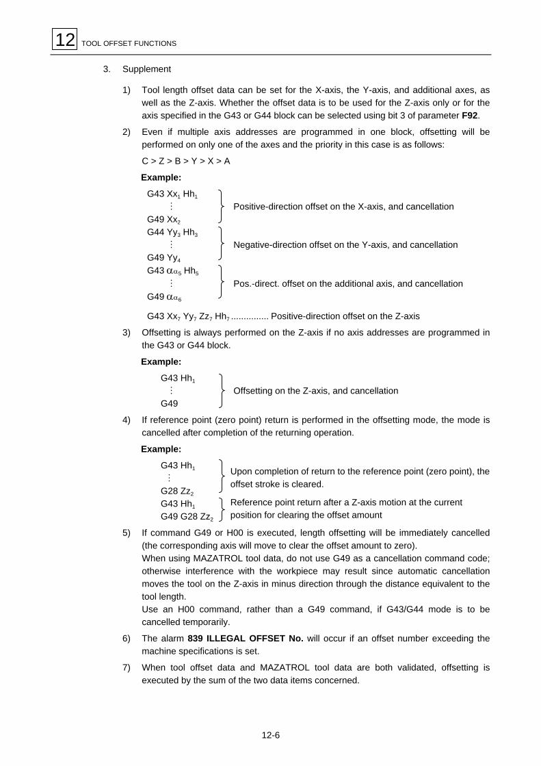
12 TOOL OFFSET FUNCTIONS
12-6
3. Supplement
1) Tool length offset data can be set for the X-axis, the Y-axis, and additional axes, aswell as the Z-axis. Whether the offset data is to be used for the Z-axis only or for theaxis specified in the G43 or G44 block can be selected using bit 3 of parameter F92.
2) Even if multiple axis addresses are programmed in one block, offsetting will beperformed on only one of the axes and the priority in this case is as follows:
C > Z > B > Y > X > A
Example:
G43 Xx1 Hh1
M Positive-direction offset on the X-axis, and cancellationG49 Xx2
G44 Yy3 Hh3
M Negative-direction offset on the Y-axis, and cancellationG49 Yy4
G43 αα5 Hh5
M Pos.-direct. offset on the additional axis, and cancellationG49 αα6
G43 Xx7 Yy7 Zz7 Hh7 ............... Positive-direction offset on the Z-axis
3) Offsetting is always performed on the Z-axis if no axis addresses are programmed inthe G43 or G44 block.
Example:
G43 Hh1
M Offsetting on the Z-axis, and cancellationG49
4) If reference point (zero point) return is performed in the offsetting mode, the mode iscancelled after completion of the returning operation.
Example:
G43 Hh1
M
G28 Zz2
G43 Hh1
G49 G28 Zz2
5) If command G49 or H00 is executed, length offsetting will be immediately cancelled(the corresponding axis will move to clear the offset amount to zero).When using MAZATROL tool data, do not use G49 as a cancellation command code;otherwise interference with the workpiece may result since automatic cancellationmoves the tool on the Z-axis in minus direction through the distance equivalent to thetool length.Use an H00 command, rather than a G49 command, if G43/G44 mode is to becancelled temporarily.
6) The alarm 839 ILLEGAL OFFSET No. will occur if an offset number exceeding themachine specifications is set.
7) When tool offset data and MAZATROL tool data are both validated, offsetting isexecuted by the sum of the two data items concerned.
Upon completion of return to the reference point (zero point), theoffset stroke is cleared.
Reference point return after a Z-axis motion at the currentposition for clearing the offset amount

TOOL OFFSET FUNCTIONS 12
12-7
12-3 Tool Position Offset: G45 to G48
1. Function and purpose
Command G45 or G46 allows the axis movement distance set previously in that block to beincreased or decreased, respectively, according to the offset data. Likewise, command G47 orG48 extends or contracts the previously set distance by twice the offset stroke, respectively.
G45 command G46 command
Extended thru offset stroke onlyContracted thru
offset stroke only
Internalcalculation
Movingstroke
Startingpoint
Endingpoint Starting
point
Internalcalculation
Movingstroke
Endingpoint
G47 command G48 command
Extended thru twicethe offset stroke
Contracted thru twicethe offset stroke
Internalcalculation
Movingstroke
Endingpoint
Startingpoint
Startingpoint
Internalcalculation
Movingstroke
Endingpoint
± =
2. Programming format
Programming format Function
G45 Xx DdTo extend a moving stroke by the offset stroke which has been set in the offsetmemory.
G46 Xx DdTo contract a moving stroke by the offset stroke which has been set in the offsetmemory.
G47 Xx DdTo extend a moving stroke by twice the offset stroke which has been set in theoffset memory.
G48 Xx DdTo contract a moving stroke by twice the offset stroke which has been set in theoffset memory.
(Program command value) (Offset stroke) (Moving stroke after offset)

12 TOOL OFFSET FUNCTIONS
12-8
3. Detailed description
- Programming based on incremental data is shown below.
Tape commandStroke of movement by
equivalent tape command(selected offset stroke = l)
Example(with x = 1000)
G45 Xx Dd X {x + l} l = 10 X = 1010l = –10 X = 990
G45 X–x Dd X – {x + l} l = 10 X = –1010l = –10 X = –990
G46 Xx Dd X {x – l} l = 10 X = 990l = –10 X = 1010
G46 X–x Dd X – {x – l} l = 10 X = –990l = –10 X = –1010
G47 Xx Dd X {x + 2!l} l = 10 X = 1020l = –10 X = 980
G47 X–x Dd X – {x + 2!l} l = 10 X = –1020l = –10 X = –980
G48 Xx Dd X {x – 2!l} l = 10 X = 980l = –10 X = 1020
G48 X–x Dd X – {x – 2!l} l = 10 X = –980l = –10 X = –1020
- Even if no offset numbers are set in the same block as that which contains commands G45 toG48, offsetting will be performed, based on previously stored tool position offset numbers.
- An alarm 839 ILLEGAL OFFSET No. will occur if the designated offset number is anunavailable one.
- These G-code commands are not modal ones, and thus they are valid only for the designatedblock.
- These commands must be used in modes other than the fixed-cycle mode. They will beignored if used in the fixed-cycle mode.
- The axis will move in reverse if internal calculation for changing the movement distance resultsin inversion of the direction of movement.
Program command: G48 X20.000Offset stroke: + 15.000
Real movement: X–10.000
MEP060
Starting point
Ending point
- The following lists how the machine operates if a movement distance of 0 using the incrementaldata command mode (G91) is programmed:
NC command G45 X0 D01 G45 X–0 D01 G46 X0 D01 G46 X–0 D01Equivalent command X1234 X–1234 X–1234 X1234
D01: Offset number1234: Offset amount for D01
For absolute data commands, if the movement distance is set equal to 0, the block will beimmediately completed and no movement through the offset distance will occur.

TOOL OFFSET FUNCTIONS 12
12-9
- When absolute data commands are used, each axis will also move from the ending pointpreset in the preceding block to the position set in the block that contains commands G45through G48.That is, when absolute data commands are used, offsetting will be performed according to themovement distance (increments in distance) set in that block.
4. Sample programs
1. During arc interpolation, tool diameter offsetting using commands G45 to G48 can be doneonly for a 1/4, 1/2, or 3/4 circle whose starting and ending points are present on a coordinateaxis passing through the arc center.
MEP061
(D01 = 200)G91 G45 G03 X–1000 Y1000 I–1000 F1000 D01
1000
Y
X
200
1000
Ending point
Tool
Tool center path
Program path
Starting pointProgram arc center
Tool position offset, with 1/4 arc command given
2. If an “n” number of axes are designated at the same time, the same amount of offsetting willbe performed on all designated axes. This also applies to additional axes, but within thelimits of the simultaneously controllable axis quantity.
X
Y
220. 270.
110.
60.50.
50.
G01 G45 X220. Y60. D20(D20 = +50.000)
Starting point
Ending point on the program
Ending point after offset
MEP062

12 TOOL OFFSET FUNCTIONS
12-10
Note: Use tool diameter offset commands G40, G41, or G42 if simultaneous offsetting of twoaxes is likely to result in excessive or insufficient cutting as shown below.
MEP063
l
X
Y
Desirable shape
Machining shape
Insufficient cutting
Tool
Tool center pathProgram path
G01 G45 Xx1 Dd1
Xx2 Yy2
G45 Yy3
l: Set value of offset stroke
Workpiece
MEP064
l
X
Y
Machining shape
Desirable shape
Excessive cutting
Tool
Tool center pathProgram path
G01 Xx1
G45 Xx2 Yy2 Dd2
Yy3
l: Set value of offset stroke
Workpiece

TOOL OFFSET FUNCTIONS 12
12-11
3. Cornering in a 1/4 circle
MEP065
X
Y
N4
N3
N2
N1
Tool center path
Program path N1 G46 G00 Xx1 Yy1 Dd1
N2 G45 G01 Yy2 Ff2
N3 G45 G03 Xx3 Yy3 Ii3N4 G01 Xx4
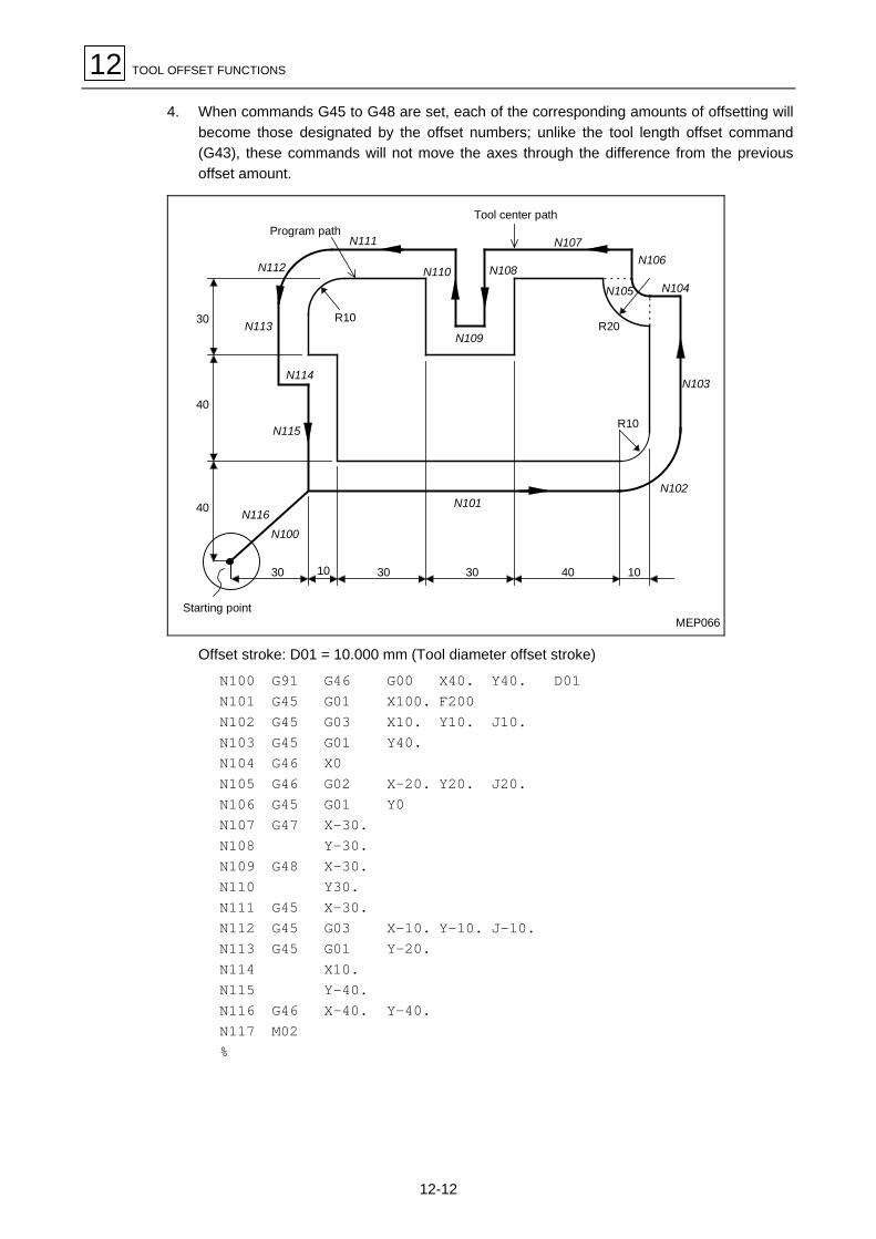
12 TOOL OFFSET FUNCTIONS
12-12
4. When commands G45 to G48 are set, each of the corresponding amounts of offsetting willbecome those designated by the offset numbers; unlike the tool length offset command(G43), these commands will not move the axes through the difference from the previousoffset amount.
MEP066
Tool center path
R10
40
40
30
N112
N113
N114
N115
N116N100
30 3010 30 40 10
N101N102
N103
N104
R20
N105
N106N107
N108
N109
N110
N111
R10
Program path
Starting point
Offset stroke: D01 = 10.000 mm (Tool diameter offset stroke)
N100 G91 G46 G00 X40. Y40. D01N101 G45 G01 X100. F200N102 G45 G03 X10. Y10. J10.N103 G45 G01 Y40.N104 G46 X0N105 G46 G02 X–20. Y20. J20.N106 G45 G01 Y0N107 G47 X–30.N108 Y–30.N109 G48 X–30.N110 Y30.N111 G45 X–30.N112 G45 G03 X–10. Y–10. J–10.N113 G45 G01 Y–20.N114 X10.N115 Y–40.N116 G46 X–40. Y–40.N117 M02%

TOOL OFFSET FUNCTIONS 12
12-13
12-4 Tool Diameter Offset Function: G40, G41, G42
12-4-1 Overview
1. Function and purpose
Offsetting in any vectorial direction can be done according to the tool radius preselected usingG-codes (G38 to G42) and D-codes. This function is referred to as tool diameter offsetting.
For turning tools, nose-R compensation can be performed according to the designated direction(only when TOOL OFFSET type C is selected).
2. Programming format
Command format Function Remarks
G40X_Y_ To cancal a tool diameter offset
G41X_Y_ To offset a tool diameter (Left)
G42X_Y_ To offset a tool diameter (Right)
G38 I_J_ To change and hold an offset vector
G39 To interpolate a corner arcThese commands can be givenduring the diameter offset mode.
3. Detailed description
For tool diameter offsetting, all H-code commands are ignored and only D-code commandsbecome valid.Also, tool diameter offsetting is performed for the plane that is specified by either the planeselection G-code command or two-axis address code command appropriate for tool diameteroffsetting. No such offsetting is performed for axes other than those corresponding or parallel tothe selected plane. See Section 6-7 to select a plane using a G-code command.
12-4-2 Tool diameter offsetting
1. Tool diameter offsetting cancellation
Tool diameter offsetting is automatically cancelled in the following cases:
- After power has been turned on
- After the reset key on the NC operation panel has been pressed
- After M02 or M30 has been executed (these two codes have a reset function)
- After G40 (offsetting cancellation command) has been executed
In the offsetting cancellation mode, the offset vector becomes zero and the tool center pathagrees with the programmed path.Programs containing the tool diameter offset function must be terminated during the offsettingcancellation mode. Give the G40 command in a single-command block (without any other G-code). Otherwise it may be ignored.

12 TOOL OFFSET FUNCTIONS
12-14
2. Startup of tool diameter offsetting
Tool diameter offsetting will begin during the offset mode when all the following three conditionsare met:
- Command G41 or G42 has been executed.
- The offset number for tool diameter offsetting is larger than zero, but equal to or smaller thanthe maximum available offset number.
- The command used with the offsetting command is a move command other than those used forarc interpolation.
Offsetting will be performed only when reading of five blocks in succession is completed,irrespective of whether the single-block operation mode is used.During offsetting, five blocks are pre-read and then calculation for offsetting is performed.
MEP067
S_
S_
G00_
G01_
G02_G41_
G00_ G41_
G01_
G01_ G02_
T_
T_ S_ G00_ G41_ G01_ G02_
G02_
Work program
Offset buffer
Pre-read buffer
Blocks executed
Start of pre-readingfive blocks
Control Status
T_
There are two types of offsetting startup operation: Type A and Type B.It depends on the setting of bit 4 of parameter F92 whether Type A or Type B is automaticallyselected.These two types of startup operation are similar to those of offsetting cancellation.In the descriptive diagrams below, “s” signifies the ending point of single-block operation.
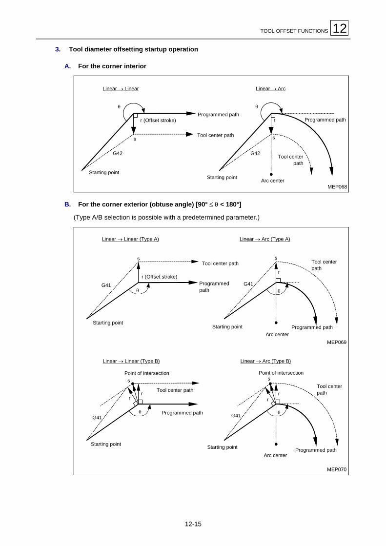
TOOL OFFSET FUNCTIONS 12
12-15
3. Tool diameter offsetting startup operation
A. For the corner interior
θ
s
G42
θ
r
s
G42
r (Offset stroke)
Starting point
Linear → Linear
Programmed path
Tool center path
Starting point
Linear → Arc
Programmed path
Tool centerpath
Arc centerMEP068
B. For the corner exterior (obtuse angle) [90° ≤ θ < 180°]
(Type A/B selection is possible with a predetermined parameter.)
θ
s
G41
r
s
G41θ
r (Offset stroke)
Starting point
Linear → Linear (Type A)
Programmedpath
Tool center path
Starting point
Linear → Arc (Type A)
Programmed pathArc center
Tool centerpath
MEP070
θ
s
G41
rr
rr
s
G41 θ
Starting point
Linear → Linear (Type B)
Programmed path
Tool center path
Starting point
Linear → Arc (Type B)
Programmed pathArc center
Tool centerpath
Point of intersection Point of intersection
MEP069

12 TOOL OFFSET FUNCTIONS
12-16
C. For the corner exterior (sharp angle) [θ < 90°]
(Type A/B selection is possible with a predetermined parameter.)
MEP071
r
s
θ
G41
r
s
θ
G41
r
s
θr
G41
r
s
θr
G41
Starting point
Tool center path
Linear → Linear (Type A)
Starting point
Linear → Arc (Type A)
Arc center
Programmed path
Tool center path
Linear → Linear (Type B)
Starting point
Starting point
Linear → Arc (Type B)
Programmed path
Arc center
4. Operation during the offset mode
Offsetting is performed for linear or arc interpolation commands and positioning commands.Identical offset commands G41 or G42 will be ignored if they are used during the offset mode.
Successive setting of four or more blocks that do not involve movement of axes during the offsetmode may result in excessive or insufficient cutting.

TOOL OFFSET FUNCTIONS 12
12-17
A. For the corner exterior
Tool center path
θ
Arc center
rr
s
Programmed path
Arc center
Arc → Arc (90° ≤ θ < 180°)
Arc center
Arc → Arc (0° < θ < 90°)
Tool center path
Arc center
Programmed path
θ
r r
MEP072
s
θ
s
Linear → Linear (90° ≤ θ < 180°)
Programmed path
Tool center path
Linear → Linear (0° < θ < 90°)
Programmed path
Tool center pathr
sθ
r
r
sθr
Programmed path
Tool center path
Arc center
Linear → Arc (0° < θ < 90°)
r
θ
r
Arc center
Programmed path
Tool center path
Arc → Linear ( 0° < θ < 90° )
s
rr
s
θ
Arc → Linear (90° ≤ θ < 180°)
Programmed path
Tool center path
Arc center
Programmed path
Tool center path
Linear → Arc (90° ≤ θ < 180°)
Arc center
θ
rr
s

12 TOOL OFFSET FUNCTIONS
12-18
B. For the corner interior
r
θArc center
Programmed path
Arc center
Tool center path
s
θ
r
r
s
Linear → Arc (Obtuse angle)
Programmed path
Tool center path
Arc center
θ
rs
Arc center
Arc → Linear (Obtuse angle)
Programmed path
Tool center path
θr
r
s
Linear → Linear (Obtuse angle)
Programmed path
Tool center path
Linear → Arc (Obtuse angle)
θ
r
Programmed path
Tool center path
Arc center
s
Linear → Linear (Obtuse angle)
s
Programmed path
Tool center path
θ
rr
r
θ
sProgrammed path
Arc center
Tool center path
Arc → Linear (Obtuse angle)
Arc → Arc (Sharp angle)
MEP073
Arc → Arc (Obtuse angle)
Arc center
r
s
θ
Programmed path
Arc center
Tool center path

TOOL OFFSET FUNCTIONS 12
12-19
C. For an arc that does not have the ending point on it
The area from the starting point of the arc to the ending point is interpolated as a spiral arc.
MEP074
Tool center path
Arc ending point
Virtual circle
Programmed path
Arc center
r
r
R
s
D. For arcs that do not have their inner crossing point
In cases such as those shown in the diagram below, there may or may not be a crossing point ofarcs A and B, depending on the particular offset data. In the latter case, the program terminatesat the ending point of the preceding block after an alarm 836 NO INTERSECTION has beendisplayed.
r
A B
r
Center of Arc A
Stop with program error
MEP075
Tool center path
Programmed path
Line of intersectionpoints betweenArcs A and B
5. Tool diameter offsetting cancellation
During the tool diameter offset mode, tool diameter offsetting will be cancelled in any of the twocases listed below.
- Command G40 has been executed.
- Offset number code D00 has been executed.
At this time, however, the move command executed must be one other than those used for arcinterpolation. An alarm 835 G41, G42 FORMAT ERROR will occur if an attempt is made tocancel offsetting using an arc command.
After the offsetting cancellation command has been read into the offset buffer, the cancellationmode is set automatically and subsequent blocks of data are read into the pre-read buffer, notthe offset buffer.
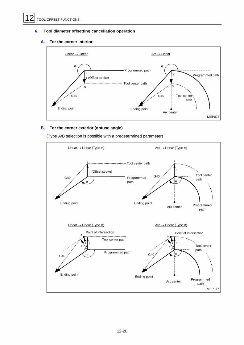
12 TOOL OFFSET FUNCTIONS
12-20
6. Tool diameter offsetting cancellation operation
A. For the corner interior
MEP076
r (Offset stroke)
Ending point
Linear → Linear
Programmed path
Tool center path
Ending point
Arc → Linear
Programmed path
Tool centerpath
Arc center
θ
s
G40
θ
r
s
G40
B. For the corner exterior (obtuse angle)
(Type A/B selection is possible with a predetermined parameter)
θ θ
s
G40
rr
r (Offset stroke)
Ending point
Linear → Linear (Type A)
Programmedpath
Tool center path
Ending point
Arc → Linear (Type A)
Programmedpath
Arc center
Ending point
Linear → Linear (Type B)
Programmed path
Tool center path
Ending point
Arc → Linear (Type B)
Programmedpath
Point of intersection
Arc center
Point of intersection
rr
s
G40
s
G40
r
s
G40θ θ
MEP077
Tool centerpath
Tool centerpath

TOOL OFFSET FUNCTIONS 12
12-21
C. For the corner exterior (sharp angle)
(Type A/B selection is possible with a predetermined parameter)
r
s
θr
G40
r
s
θr
G40
Programmed path
Tool center path
Linear → Linear (Type A)
Ending point
Arc → Linear (Type A)
Programmed path
Tool center path
Linear → Linear (Type B)
Ending point
Ending point
Arc centerArc → Linear (Type B)
Arc center
Ending point
r
s
θ
G40
r
s
θ
G40
MEP079

12 TOOL OFFSET FUNCTIONS
12-22
12-4-3 Tool diameter offsetting operation using other commands
1. Interpolation of the corner arc
When command G39 (corner-arc interpolation) is used, the coordinates of the crossing points atworkpiece corners will not be calculated and an arc with offset data as its radius will beinterpolated.
r
Programmed path
Tool center path
Interpolated arc
(G39 command given) (Without G39 command)
Point ofintersection
Programmed path
Tool center path
Interpolated arc
Outside Offset Inside Offset(G39 command given)
(Without G39 command )
r
Point of intersection
MEP080
2. Changing/retaining offset vectors
Using command G38, you can change or retain offset vectors during tool diameter offsetting.
- Retaining vectorsSetting G38 in block that contains move commands allows crossing-point calculation at theending point of that block to be cancelled and the vectors in the preceding block to be retained.This can be used for pick and feed operations.
G38 Xx Yy
- Changing vectorsThe directions of new offset vectors can be designated using I, J, and K (I, J, and K depend onthe selected type of plane), and offset data can be designated using D. (These commands canbe included in the same block as that which contains move commands.)
G38 Ii Jj Dd
N13r1
N12
N11
N14N15
r1
N16
i j
i2 + j2
jr2 = × r1
N11G1Xx11 N12G38Yy12 N13G38Xx13 N14G38Xx14Yy14 N15G38Xx15IiJjDd2 N16G40Xx16Yy16
Programmed path
Tool center path
Vector held Vector changed NEP081

TOOL OFFSET FUNCTIONS 12
12-23
3. Changing the offset direction during tool diameter offsetting
The offset direction is determined by the type of tool diameter offset command (G41 or G42) andthe sign (plus or minus) of the offset data.
Offset stroke signG-code
+ –
G41 Left side offset Right side offset
G42 Right side offset Left side offset
The offset direction can be changed by updating the offset command without selecting theoffsetting cancellation function during the offset mode. This can, however, be done only forblocks other than the offset startup block and the next block. See subsection 12-4-6, Generalprecautions on tool diameter offsetting, for NC operation that will occur if the sign is changed.
MEP082
r
rr
r
G41 G41 G42
Point of intersectionProgrammed path
Tool center path
This figure shows anexample in which no pointsof intersection are presentduring offset directionchange.
Linear → Linear
G41 G42 G41 G41 G42
r
r
r
r
r
r
Programmed path
Tool center path
Linear ↔Arc
Arc → Arc
G41
G41
Programmed path
Tool center path G42
G42G41
G41 G42
r
r
Arc center
Arc center

12 TOOL OFFSET FUNCTIONS
12-24
MEP083
r
G41
G42Tool center path
Programmed path
Linear turnaround
The arc of more than 360 degrees may result in the following cases:
- The offset direction has been changed by G41/G42 selection.
- Commands I, J, and K have been set for G40.
Programmed path
Tool center path
Arc of 360° or more (depends on the offsetting method used)
G42
G41G42
MEP084
4. Cases where the offset vectors are temporarily lost
If the command listed below is used during the offset mode, the current offset vectors will be losttemporarily and then the NC unit will re-enter the offset mode.In that case, movements for offsetting cancellation will not occur and program control will betransferred from one crossing-point vector directly to the vector-less point, that is, to theprogrammed point. Control will also be transferred directly to the next crossing point when theoffset mode is re-entered.

TOOL OFFSET FUNCTIONS 12
12-25
A. Reference-point return command
MEP085
(G41) MN5 G91 G01 X–60. Y–30.N6 G28 X–50. Y+40.N7 X–30. Y+60.N8 X–70. Y–40.
M
Intermediate point
← Temporary vector 0 as offset at the intermediatepoint (reference point when the intermediate point isnot available)
s s
s
N5 N6 N7 N8
5. Blocks that do not include movement
The blocks listed below are referred to as those which do not include movement:
M03................................................. M commandS12................................................. S commandT45................................................. T commandG04 X500 ...................................... DwellG22 X200. Y150. Z100........... To set a machining-prohibited areaG10 P01 R50 ............................... To set an offset strokeG92 X600. Y400. Z500........... To set a coordinate system(G17) Z40. .................................... To move outside the offsetting planeG90................................................. G code onlyG91 X0 .......................................... Moving stroke 0 ...........Moving stroke is 0.
A. When a block that does not include movement is set during the start of offsetting
Vertical offsetting will be performed on the next move block.
N2
N1
N3
N4
N1 X30. Y60.N2 G41 D10N3 X20. Y–50.N4 X50. Y–20.
MEP086
← Move-free block
Move-free

12 TOOL OFFSET FUNCTIONS
12-26
Offset vectors, however, will not be generated if four or more blocks that do not include movecommands appear in succession.
N1
N7
N8
N2 to N6N1 X30. Y60.N2 G41 D10N3 G4 X1000N4 F100N5 S500N6 M3N7 X20. Y–50.N8 X50. Y–20. (Point of intersection)
Move-free blocks
MEP087
N1 G41 X30. Y60. D10N2 G4 X1000N3 F100N4 S500N5 M3N6 X20. Y–50.N7 X50. Y–20.
N1
N6
N7
N2 to N5
(Point of intersection)
Move-free blocks
MEP088
B. When a block that does not include movement is set during the offset mode
Usual crossing-point vectors will be generated unless four or more blocks that do not includemovement appear in succession.
N6
N7 N8
N8
N6 Block N7 is executed here.
N6 G91 X100. Y200.N7 G04 P1000N8 X200. ← Move-free block
MEP089
Vertical offset vectors will be generated at the end point of preceding block if four or more blocksthat do not include movement appear in succession.

TOOL OFFSET FUNCTIONS 12
12-27
MEP090
N7 to N10
N6
N11
N11
N6
N6 X100. Y200.N7 G4 X1000N8 F100N9 S500N10 M4N11 X100.
Move-free blocks
In this case, excessive cutting may occur.
C. When a block that does not include movement is set together with offsettingcancellation
Only offset vectors will be cancelled if the block that does not include movement contains G40.
N6 X100. Y200.N7 G40 G04P1000N8 X100. Y50.
N6
N7
N8
MEP091
6. If I, J, and K are set with G40
When the last of the four move command blocks which immediately precede the G40 commandblock contains G41 or G42, movement will be handled as if it had been programmed to occur inthe vectorial direction of I, J, and K from the ending point of that last move command. That is, thearea up to the crossing point with the virtual tool center path will be interpolated and thenoffsetting will be cancelled. The offset direction will remain unchanged.
rrN1
N2
G41
A
(i, j)
(a, b) Virtual tool center path
Tool center path
Programmed path
N1 (G41) G1 X_N2 G40XaYbIiJj
MEP092

12 TOOL OFFSET FUNCTIONS
12-28
In this case, beware that irrespective of the offset direction, the coordinates of the crossing pointwill be calculated even if wrong vectors are set as shown in the diagram below.
r
(a, b)
A
N1G41
N2
r
(i, j)
Tool center path
Virtual tool center path
Programmed path
Where I and J in the sample programshown above have wrong signs
MEP093
Also, beware that a vertical vector will be generated on the block before that of G40 if crossing-point calculation results in the offset vector becoming too large.
MEP094
r
(a, b)
AG41
G40
(i, j) r
Tool center path
Programmed path
Virtual tool center path
Note: Part of the workpiece will be cut twice if the I/J/K command data in G40 preceded by anarc command generates an arc of more than 360 degrees.
MEP095
G42
N2
r
N1
(i, j)
G40
r
r
N3
Programmed path
Tool center path
N1 (G42, G91) G01X200.N2 G02 J150.N3 G40 G1X150. Y–150.I–100. J100.

TOOL OFFSET FUNCTIONS 12
12-29
12-4-4 Corner movement
If multiple offset vectors are generated at connections between move command blocks, the toolwill move linearly between those vectors. This action is referred to as corner movement.If the multiple vectors do not agree, the tool will move around the corresponding corners (but thismovement belongs to the next block). During single-block operation, the section of (Precedingblock + Corner movement) is executed as one block and the remaining section of (Connectionsmovement + Next block) is executed during next movement as another block.
MEP096
r
r
N1
N2
Stopping point in thesingle block mode
Arc center
Programmed path
Tool center path
This movement and itsfeedrate belong to Block N2.
12-4-5 Interruptions during tool diameter offsetting
1. Interruption by MDI
Tool diameter offsetting is valid during automatic operation, whether it is based on the tape,memory, or MDI operation mode.The following diagrams show what will occur if tape or memory operation is interrupted using theMDI function following termination of the program at a block:
A. Interruption without movement
No change in tool path
N1 G41D1N2 X–20. Y–50.N3 G3 X–40. Y40. R70. S1000 M3
MDI interruption
N2N3
s (Stop position in thesingle block mode)
MEP097

12 TOOL OFFSET FUNCTIONS
12-30
B. Interruption with movement
The offset vectors are recalculated automatically at the first effective move block afterinterruption.
MEP098
N2N3
s
s
N1 G41D1N2 X–20. Y–50.N3 G3 X–40. Y40. R70. X–50. Y30.
X–30. Y–50.
MDI interruption
Linear interruption
N2 N3
s
s
MEP099
N1 G41D1N2 X–20. Y–50.N3 G3 X–40. Y40. R70. G2 X–40. Y–40. R70.
G1 X–40.
MDI interruption
Arc interruption
2. Manual interruption
- For the incremental data command mode, the tool path shifts through the interruption amount.
- For the absolute data command mode, the intended tool path is restored at the ending point ofthe block immediately following that at which interruption has been performed. This state isshown in the diagram below.
Interruption Interruption MEP100

TOOL OFFSET FUNCTIONS 12
12-31
12-4-6 General precautions on tool diameter offsetting
1. Selecting the amounts of offset
The amounts of offset are selected by specifying an offset number using a D-code. Once a D-code has been used, it will remain valid until a second D-code is used. No H-codes can be usedto make these selections.D-codes are also used to select tool position offset data.
2. Updating the selected amounts of offset
Updating of the selected amounts of offset is usually to be done after a different tool has beenselected during the diameter offsetting cancellation mode. If such updating is done during theoffset mode, vectors at the ending point of a block will be calculated using the offset dataselected for that block.
3. The sign of offset data and the tool center path
Minus-signed (–) offset data generates the same figure as that obtained when G41 and G42 areexchanged each other. Therefore, the tool center will move around the inside of the workpiece ifit has been moving around the outside. Conversely, the tool center will move around the outsideof the workpiece if it has been moving around the inside.Sample programs are shown below. Usually, offset data is to be programmed as plus (+) data. Ifthe tool center has been programmed to move as shown in diagram (a) below, the movementcan be changed as shown in diagram (b) below by changing the sign of the offset data to minus(–). Conversely, if the tool center has been programmed to move as shown in diagram (b) below,the movement can be changed as shown in diagram (a) below by changing the sign of the offsetdata to plus (+). One tape for machining of both inside and outside shapes can be created in thisway. Also, a dimensional tolerance between both shapes can be freely set by selectingappropriate offset data (however, Type A is to be used during the start of offsetting or during itscancellation).
Tool center path Tool center path
Workpiece
Workpiece
G41 offset stroke positive orG42 offset stroke negative
(a)
G41 offset stroke negative orG42 offset stroke positive
(b)
MEP101

12 TOOL OFFSET FUNCTIONS
12-32
12-4-7 Offset number updating during the offset mode
In principle, offset numbers should not be updated during the offset mode. If updating is done,the tool center will move as shown below.
If an offset number (offset data) is updatedG41 G01 Dr1
M
M
M α = 0, 1, 2, 3N101 G0α Xx1 Yy1
N102 G0α Xx2 Yy2 Dr2 To change an offset numberN103 Xx3 Yy3
1. Line-to-line movement
r1
r1
r2
r2
N102
N103N101
r1
r1
r1
r1
r2
r2
N102
N101
N103
Programmed path
Tool center path
The offset stroke selectedin N101 will be used.
The offset stroke selectedin N102 will be used.
Programmed path
Tool center path
MEP102

TOOL OFFSET FUNCTIONS 12
12-33
2. Line-to-arc movement
r1r1
r2
N102G02
N101
N101
G03N102
r2
r1
r1
r1
r1
Arc center
Tool center path
Programmed path
Tool center path
Programmed path
Arc centerMEP103
3. Arc-to-arc movement
Tool center path
Tool center path
Programmed path
Programmed path
Arc center
Arc center
Arc center
Arc center
r2
r1
r1
N101
N102
r1
r1
r1
r2
r1N101N102
MEP104

12 TOOL OFFSET FUNCTIONS
12-34
12-4-8 Excessive cutting due to tool diameter offsetting
If an interference check function is not provided, excessive cutting may result in the followingthree cases:
1. Machining of the inside of an arc smaller than the tool radius
If the radius of the programmed arc is smaller than that of the tool, excessive cutting may resultfrom offsetting of the inside of the arc.
MEP105
R
Programmed path
Programmed arc
Excessive cutting
Tool center
2. Machining of a groove smaller than the tool radius
Excessive cutting may result if tool diameter offsetting makes the moving direction of the toolcenter opposite to that of the program.
MEP106
Oppositedirection
Tool center path
M
Programmed path
Excessive cutting
3. Machining of a stepped section smaller than the tool radius
MEP107
Tool center path
Programmed path
Excessive cutting

TOOL OFFSET FUNCTIONS 12
12-35
4. Relationship between the start of tool diameter offsetting and the cutting operation in theZ-axis direction
It is generally done that diameter offsetting (usually, on the X-Y plane) is done at a suitabledistance from the workpiece during the start of cutting and then the workpiece is cut along theZ-axis. At this time, incorporate the following programming considerations if you want to split theZ-axis action into rapid feed and cutting feed which is to follow only after the Z-axis has movedclose to the workpiece:If you make a program such as that shown below:
N1 G91 G00 G41 X500. Y500. D1N2 S1000N3 M3N4 G01 Z–300. F1N6 Y100. F2 . . . .
N6
N1
Y
X
N6
N1
N4
Y
Z
Tool center path
N4: Z axis movesdownward(1 block)
MEP108
With this program, all blocks up to N6 can be read during the start of offsetting based on N1.Thus, the NC unit will judge the relationship between N1 and N6 and correctly perform the offsetoperation as shown in the diagram above.A sample program in which the N4 block in the program shown above has been split into twoparts is shown below.
N1 G91 G00 G41 X500. Y500. D1N2 S1000N3 M3N4 Z–250.N5 G01 Z–50. F1N6 Y100. F2
X XN1
Y
N6
Z
N1
N4
N5N6
Excessivecutting
MEP109
In this case, the N2 through N5 blocks do not have any command corresponding to the X-Yplane and the relevant block N6 cannot be read during the start of offsetting based on N1. As aresult, offsetting will be based only on the information contained in the N1 block and thus the NCunit will not be able to create offset vectors during the start of offsetting. This will causeexcessive cutting as shown in the diagram above.
Even in such a case, however, excessive cutting can be prevented if a command code thatmoves the tool in exactly the same direction as that existing after the Z-axis has moveddownward is included immediately before the Z-direction cutting block.

12 TOOL OFFSET FUNCTIONS
12-36
N1 G91 G00 G41 X500. Y400. D1N2 Y100. S1000N3 M3N4 Z–250.N5 G01 Z–50. F1N6 Y100. F2
N1Y
X
N6
N1Y
Z
N6
N2
N6
N5N2
N4
MEP110
For the sample program shown above, correct offsetting is ensured since the moving direction ofthe tool center at N2 is the same as at N6.
12-4-9 Interference check
1. Overview
Even a tool whose diameter has been offset by usual tool-diameter offsetting based on two-blockpre-reading may move into the workpiece to cut it. This status is referred to as interference, anda function for the prevention of such interference is referred to as interference check.The following two types of interference check are provided and their selection is to be madeusing bit 5 of parameter F92.
Function Parameter Operation
Interference checkand alarm
Interference check andprevention off
The system will stop, with a program errorresulting before executing the cutting block.
Interference checkand prevention
Interference check andprevention on
The path is changed to prevent cutting fromtaking place.

TOOL OFFSET FUNCTIONS 12
12-37
Example:
(G41)N1 G90 G1 X–50. Y–100.N2 X–70. Y–100.N3 X–120. Y0
N1 N3
N2
Interference prevention path
Tool outsidediameter
Cutting by N2Cutting by N2
MEP111
- For the alarm functionAn alarm occurs before N1 is executed. Machining can therefore be proceeded with byupdating the program into, for example,N1 G90 G1 X–20. Y–40.using the buffer correction function.
- For the prevention functionInterference prevention vectors are generated by N1 and N3 crossing-point calculation.
MEP112
[1]
[2]+
[3]’ [4]’
[1]’[4]
N3
N2
N1
[3][2]’
Vector [1] [4]' check → No interference ↓Vector [2] [3]' check → No interference ↓Vector [3] [2]' check → Interference → Vector [3] [2]' deletion → Vector [4] [1]' deletion
The above process is performed to leave vectors [1] [2] [3]' and [4]' as effective ones. Resultantly,the route that connects vectors [1] [2] [3]' and [4] is taken as a bypass for the prevention ofinterference.

12 TOOL OFFSET FUNCTIONS
12-38
2. Detailed description
A. The case where interference is regarded as occurring
When move commands are present in three of the five command blocks to be pre-read,interference will be regarded as occurring, if the offset calculation vectors at the blockconnections of the individual move commands intersect.
MEP113N2
N3N1
r
Tool center path
Programmed path
Vectors intersect.
B. Cases where interference check cannot be performed
- When pre-reading of three move command blocks of the five to be pre-read is not possible(since the three blocks do not contain move commands).
- When the fourth and subsequent move command blocks themselves interfere.
N1
N2
N3 N4
N5
N6
Interference cannot be checked
Programmed path
Tool center path
MEP114
C. Movements during the prevention of interference
The following shows the movements occurring when interference prevention is provided:
MEP115N2
N3N1
Programmedpath
Tool center path

TOOL OFFSET FUNCTIONS 12
12-39
MEP116
N3N2
N1
N3N2
N1 r
r
Tool center path with interference prevented
Tool center path without interference check
Programmed path
Solid-line indicated vector: ValidDotted-line indicated vector: Invalid
Programmed path
Linear move
Arc center
Tool center path with interference prevented
Tool center path without interference check
N3
N2
N2
N4
r2
r1
r1r2
N1
N1
N3
Prevention vector
Prevention vector Tool center path
Programmed path
Programmed path
Prevention vector 1Prevention vector 2
Tool center path 2 Tool center path 1
Once all interference preventionlinear vectors have been erased,a new prevention vector is madeas shown at right. Thus,interference is prevented.
MEP117

12 TOOL OFFSET FUNCTIONS
12-40
In the diagram shown below, part of the groove is left uncut:
Programmed path
Tool center path
Interference prevention path
MEP118
3. Interference alarm
Cases that an interference alarm 837 TOOL OFFSET INTERFERENCE ERROR occurs arelisted below.
When interference check and alarm is selected
1) If all vectors at the ending point of the current block are erased:Prior to execution of N1, a program error will result if vectors 1 through 4 at the ending pointof the N1 block are all erased as shown in the diagram below.
N34
2, 3
1
N1
N2
MEP119

TOOL OFFSET FUNCTIONS 12
12-41
When interference check and prevention is selected
2) If all vectors at the ending point of the current block are erased but an effective vector(s)remains at the ending point of the next block:
- For the diagram shown below, interference checking at N2 will erase all vectors existing atthe ending point of N2, but leave the vectors at the ending point of N3 effective.At this time, a program error will occur at the ending point of N1.
N1
2 1
43
N4
N3
N2Alarm stop
MEP120
- For the diagram shown below, the direction of movement becomes opposite at N2.At this time, a program error will occur before execution of N1.
N1
N2 N3
N4
1, 2, 3, 4
MEP121

12 TOOL OFFSET FUNCTIONS
12-42
3) When prevention vectors cannot be generated:Prevention vectors may not be generated even when the conditions for generating them aresatisfied. Or even after generation, the prevention vectors may interfere with N3.A program error will therefore occur at the ending point of N1 if those vectors cross atangles of 90 degrees or more.
MEP122
θ
N1N1
N2 N2
N3
N3
N4
N4
Alarm stop Alarm stop
θ: Intersection angle
4) When the after-offsetting moving direction of the tool is opposite to that of the program:For a program for the machining of parallel or downwardly extending grooves narrower thanthe tool diameter, interference may be regarded as occurring even if it is not actuallyoccurring.
StopProgrammed path
Tool center path
MEP123

TOOL OFFSET FUNCTIONS 12
12-43
12-5 Three-Dimensional Tool Diameter Offsetting (Option)
Three-dimensional tool diameter offsetting is performed to offset a tool in three-dimensionalspace according to the previously designated three-dimensional vectors.
12-5-1 Function description
MEP124
Tool radiusr Z (K)
Y (J) X (I)
Tool
Tool center coordinates(x’, y’, z’) (I, J, K) Plane-normal vector
3-dimensional offset vector
Workpiece
Program coordinates(x, y, z)
As shown in the diagram above, the tool is moved through the tool radius r in the plane-normalvectorial direction of (I, J, K) from the program coordinates (x, y, z) to the offset tool centercoordinates (x’, y’, z’). Also, unlike two-dimensional tool diameter offsetting, which generatesvectors perpendicular to the direction of (I, J, K), three-dimensional tool diameter offsettinggenerates vectors in the direction of (I, J, K). (The vectors are generated at the ending point ofthat block.) The axis components of three-dimensional offset vectors become:
I2 + J2 + K2
IHx = • r
I2 + J2 + K2
JHy = • r
I2 + J2 + K2
KHz = • r
Hence, the tool center coordinates (x’, y’, z’) are expressed as
x’ = x + Hxy’ = y + Hyz’ = z + Hz
where (x, y, z) denote the program coordinates.
Note 1: The three-dimensional vectors (Hx, Hy, Hz) refer to plane-normal vectors that areidentical to the plane-normal vectors (I, J, K) in direction and have a magnitude of r(tool radius).
Note 2: If parameter F11 is set to a value other than 0, the value of F11 will be used as
I2 + J2 + K2.

12 TOOL OFFSET FUNCTIONS
12-44
12-5-2 Programming methods
1. G-codes and their functions
Parameter and featureG-code
Offset stroke positive Offset stroke negative Offset No. D00
G40To cancel the 3-dimensional tooldiameter offset
To cancel To cancel
G41 To offset in (I, J, K) direction To offset in the direction opposite to (I, J, K) To cancel
G42To offset in the direction opposite to(I, J, K)
To offset in (I, J, K) direction To cancel
2. Offset data
For the tool radius r that is to be offset, the offset number under which that offset amount hasbeen registered must be selected using D.
3. Space in which offsetting is to be performed
The space in which offsetting is to be performed is determined by the axis address commands (X,Y, Z, U, V, W) that are contained in the starting block of three-dimensional tool diameteroffsetting. When the U-, V-, and W-axes are taken as additions to the X-, Y-, and Z-axes,respectively, priority will be given to the X-, Y-, or Z-axis if the X-axis and the U-axis (or Y and V,or Z and W) are selected at the same time. Coordinate axes that have not been addressed willbe interpreted as the X-axis, the Y-axis, and the Z-axis, respectively.
Example: G41 Xx1 Yy1 Zz1 Ii1 Jj1 Kk1 XYZ spaceG41 Yy2 Ii2 Jj2 Kk2 XYZ spaceG41 Xx3 Vv3 Zz3 Ii3 Kk3 XVZ spaceG41 Ww4 Ii4 Jj4 Kk4 XYW space
4. Starting a three-dimensional tool diameter offset operation
Offset number D and the plane-normal vectors (I, J, K) must be set in the same block as thatwhich contains three-dimensional tool diameter offset command code G41 (or G42). In that case,(I, J, K) must be set for each of the X-, Y-, and Z-axes. If this vector setting is not complete(setting of zero for I, J or K is effective), the usual tool diameter offset mode will be set. If,however, the machine does not have the three-dimensional tool diameter offset function, analarm 838 3-D OFFSET OPTION NOT FOUND will result.
G41 (G42) Xx1 Yy1 Zz1 Ii1 Jj1 Kk1 Dd1
G41 (G42) : 3-dimensional tool diameter offset command
X, Y, Z : Command to move each axis and to determine an offsetting space
I, J, K : To indicate the offsetting direction in plane-normal vectors
D : Offset number
Use the G00 or G01 mode to start the three-dimensional tool diameter offset operation. Use ofthe G02 or G03 mode results in an alarm 835 G41, G42 FORMAT ERROR.

TOOL OFFSET FUNCTIONS 12
12-45
Example 1: If move commands are present:
MEP125
G41 Xx1 Yy1 Zz1 Ii1 Jj1 Kk1 Dd1
Programmed path
Tool center path
Starting point
3-dimensional offset vector
Example 2: If move commands are not present:
MEP126
G41 Ii2 Jj2 Kk2 Dd2
Tool center path
3-dimentionaloffset vector
Starting point
5. During three-dimensional tool diameter offsetting
Set move commands and new plane-normal vector commands as follows:
Xx3 Yy3 Zz3 Ii3 Jj3 Kk3
Example 1: If move commands and plane-normal vector commands are present:
Xx3 Yy3 Zz3 Ii3 Jj3 Kk3
Starting pointProgrammed path
New vector
Tool center path
Old vector
MEP127

12 TOOL OFFSET FUNCTIONS
12-46
Example 2: If plane-normal vector commands are not present:The new vector is the same as the old one.
Xx4 Yy4 Zz4
Starting pointProgrammed path
New vector
Tool center path
Old vector
MEP128
Example 3: For arc or helical cutting:The new vector is the same as the old one.
orG02 Xx5 Yy5 (Zz5) Rr0 (Radius-selected arc).
G02 Xx5 Yy5 (Zz5) Ii0 Jj0 I and J(K) represent the center of an arc.
MEP129
Tool center path
Programmed path
Starting point
Old vector
New vector
The arc shifts through the amount of vector.
Example 4: For changing the offset data:Set offset number D in the same block as that of three-dimensional tool diameteroffset command G41 or G42. Use the G00 or G01 mode to change the offset data.Use of the arc mode results in 835 G41, G42 FORMAT ERROR.
Starting point Programmed path
New vector
Tool center path
Old vector
G41 Xx0 Yy0 Zz0 Ii0 Jj0 Kk0 Dd1
MG41 Xx6 Yy6 Zz6 Ii6 Jj6 Kk6 Dd2
MEP130

TOOL OFFSET FUNCTIONS 12
12-47
Example 5: For changing the offset direction:
G41 Xx0 Yy0 Zz0 Ii0 Jj0 Kk0 Dd1
MG42 Xx0 Yy0 Zz0 Ii0 Jj0 Kk0
Tool center path
Programmed path
New vectorStarting point
Old vector
MEP131
Use the G00 or G01 mode to change the offset direction. Use of the arc mode results in an alarm835 G41, G42 FORMAT ERROR.
6. Cancelling the three-dimensional tool diameter offset operation
Make the program as follows:
G40 Xx7 Yy7 Zz7
Use the G00 or G01 mode to cancel three-dimensional tool diameter offsetting. Use of the G02or G03 mode results in an alarm 835 G41, G42 FORMAT ERROR.
Example 1: If move commands are present:
G40 Xx7 Yy7 Zz7
Starting point
Tool center pathOld vector
Programmed path Ending point
MEP132
Example 2: If move commands are not present:
G40 (or D00)
Programmed path
Old vector Tool center path
MEP133

12 TOOL OFFSET FUNCTIONS
12-48
12-5-3 Correlationships to other functions
1. Tool diameter offsetThe usual tool-diameter offset mode will be selected if setting of plane-normal vectors (I, J,K) in the starting block of three-dimensional tool diameter offsetting is not done for each ofthe X-, Y-, and Z-axes.
2. Tool length offsetTool length offsetting is performed according to the coordinates existing after execution ofthree-dimensional tool diameter offsetting.
3. Tool position offsetTool position offsetting is performed according to the coordinates existing after execution ofthree-dimensional tool diameter offsetting.
4. Selection of fixed-cycle operation results in an alarm 901 INCORRECT FIXED CYCLECOMMAND.
5. ScalingThree-dimensional tool diameter offsetting is performed according to the coordinatesexisting after execution of scaling.
6. Home position check (G27)The current offset data is not cancelled.
12-5-4 Miscellaneous notes on three-dimensional tool diameter offsetting
1. Although they can be used to select offset numbers, D-code commands are valid only aftercommand G41 or G42 has been set. If a D-code command is not present, the previous D-code command becomes valid.
2. Use the G00 or G01 mode to change the offset mode, the offset direction or the offset data.An alarm 835 G41, G42 FORMAT ERROR will occur if an attempt is made to perform thesechanges in an arc mode.
3. During the three-dimensional tool diameter offset mode using a space, three-dimensionaltool diameter offsetting cannot be done using any other space. The cancel command code(G40 or D00) must be executed to select some other offset space.
Example: G41 X_ Y_ Z_ I_ J_ K_ To start offsetting in X, Y and Z spaceM
G41 U_ Y_ Z_ I_ J_ K_ To offset in X, Y and Z space while the U axismoves by the command value
4. Selection of an offset number falling outside the range from 1 to the maximum availablenumber of offest data results in an alarm 839 ILLEGAL OFFSET No.
5. Only the G40 or D00 command code can be used to cancel three-dimensional tool diameteroffsetting. Cancellation is not possible with the NC reset key or external reset functions.
6. A program error will result if the vectorial magnitude specified by (I, J, K), that is
I2 + J2 + K2, overflows.

TOOL OFFSET FUNCTIONS 12
12-49
12-6 Programmed Data Setting: G10
1. Function and purpose
The G10 command allows tool offset data, work offset data and parameter data to be set ormodified in the flow of program.
2. Programming formats
A. Programming workpiece offsets
- Programming format for the workpiece origin data
G10 L2 P_ X_ Y_ Z_α_ (α: Additional axis)
P: 0.....Coordinate shift (Added feature)1.....G542.....G553.....G564.....G575.....G586.....G59
Data of P-commands other than those listed above are handled as P = 1.If P-command setting is omitted, the workpiece offsets will be handled as currently effectiveones.
- Programming format for the additional workpiece origin data
G10 L20 P_ X_ Y_ Z_α_ (α: Additional axis)P1: G54.1 P1P2: G54.1 P2 M
P299: G54.1 P299P300: G54.1 P300
The setting ranges of the data at axial addresses are as follows:
Metric Inch
Linear axis ±99999.9999 mm ±9999.99999 in.
Rotational axis ±99999.9999° ±99999.9999°
B. Programming tool offsets
- Programming format for the tool offset data of Type A
G10 L10 P_R_
P: Offset numberR: Offset amount
- Programming format for the tool offset data of Type B
G10 L10 P_R_ Geometric offset concerning the lengthG10 L11 P_R_ Wear compensation concerning the lengthG10 L12 P_R_ Geometric offset concerning the diameterG10 L13 P_R_ Wear compensation concerning the diameter

12 TOOL OFFSET FUNCTIONS
12-50
The setting ranges for programming tool offset amount (R) are as follows:
Metric Inch
TOOL OFFSET Type A ±1999.9999 mm ±84.50000 in.
TOOL OFFSET Type BLength Geom. ±1999.9999 mm ±84.50000 in.
TOOL OFFSET Type BLength Wear ±99.9999 mm ±9.99999 in.
TOOL OFFSET Type BDia. Geom. ±999.9999 mm ±84.50000 in.
TOOL OFFSET Type BDia. Wear ±9.9999 mm ±0.99999 in.
C. Programming parameter data
G10 L50................ Parameter input mode ONN_P_R_N_R_G11 ...................... Parameter input mode OFF
N: Parameter numberP: Axis number (for axis type parameter)R: Data of parameter
Specify the parameters with address N as indicated below:
Parameter N: Number P: Axis No.
A 1 to 200 1001 to 1200 —
B 1 to 200 2001 to 2200 —
C 1 to 200 3001 to 3200 —
D 1 to 144 4001 to 4144 —
E 1 to 144 5001 to 5144 —
F 1 to 168 (47 to 66 excluded) 6001 to 6168 —
I 1 to 24 9001 to 9024 1 to 16
J 1 to 144 10001 to 10144 —
K 1 to 144 11001 to 11144 —
L 1 to 144 12001 to 12144 —
M 1 to 48 13001 to 13048 1 to 16
N 1 to 48 14001 to 14048 1 to 16
P 1 to 5 150001 to 150005 1 to 16(1 to 32)
# 0 to 4095(0 to 2047)
150100 to 154195(150100 to 152147)
1 to 16(1 to 32)
S 1 to 48 16001 to 16048 1 to 16
SV 1 to 384 17001 to 17384 1 to 16
SP 1 to 256 18001 to 18256 1 to 8
SA 1 to 144 19001 to 19144 1 to 8
BA 1 to 132 20001 to 20132 —
TC 1 to 154 21001 to 21154 —
SU 1 to 168 22001 to 22168 —
SD 1 to 168 23001 to 23168 —
Note 1: As for the setting ranges of parameter data, refer to the Parameter List.
Note 2: As for parameters with address P or #, data in parentheses refer to the enlargednumber of data sets for the compensation of pitch errors (when K103 bit 2 = 1).

TOOL OFFSET FUNCTIONS 12
12-51
3. Detailed description
A. Workpiece origin data input
1. The G10 command is not associated with movement. However, do not use this command inthe same block with a G-code command other than: G21, G22, G54 to G59, G90 and G91.
2. Do not use the G10 command in the same block with a fixed cycle command or a sub-program call command. This will cause a malfunctioning or a program error.
3. Irrespective of workpiece offset type (G54 - G59 and G54.1), the data to the axial addresseshave to refer to the origin of the fundamental machine coordinate system.
4. Depending upon the data input mode — absolute (G90) or incremental (G91) — thedesignated data will overwrite, or will be added to, the existing data.
5. L-code and P-code commands can be omitted, indeed, but take notice of the following whenomitting them:
1) Omit both L-code and P-code commands only when
The axial data should refer to the coordinate system that was last selected.
2) The L-code command only may be omitted when the intended axial data refer to acoordinate system of the same type (in terms of L-code: L2 or L20) as the last selectedone; give a P-command in such a case as follows:
- Set an integer from 0 to 6 with address P to specify the coordinate shift data or one ofthe coordinate systems from G54 to G59.
- Set an integer from 1 to 300 with address P to specify one of the additional workpiececoordinate systems of G54.1.
3) If the P-code command only is omitted:
An alarm will result if the value of L mismatches the coordinate system last selected.
6. Axial data without a decimal point can be entered in the range from –99999999 to+99999999. The data settings at that time depend upon the data input unit.
Example: G10 L2 P1 X–100. Y–1000 Z–100 B–1000The above command sets the following data:Metric system X –100. Y –1. Z –0.1 B –1.Metric system (up to 4 dec. places) X –100. Y –0.1 Z –0.01 B –0.1Inch system X –100. Y –0.1 Z –0.01 B –1.Inch system (up to 5 dec. places) X –100. Y –0.01 Z –0.001 B –0.1
7. The origin data updated by a G10 command are not indicated as they are on the WORKOFFSET display until that display has been selected anew.
8. Setting an illegal L-code value causes an alarm.
9. Setting an illegal P-code value causes an alarm.
10. Setting an illegal axial value causes an alarm.
11. The G10 command is invalid (or skipped) during tool path check.
B. Tool offset data input
1. The G10 command is not associated with movement. However, do not use this command inthe same block with a G-code command other than: G21, G22, G54 to G59, G90 and G91.
2. Do not use the G10 command in the same block with a fixed cycle command or a sub-program call command. This will cause a malfunctioning or a program error.

12 TOOL OFFSET FUNCTIONS
12-52
3. Depending upon the data input mode — absolute (G90) or incremental (G91) — thedesignated data will overwrite, or will be added to, the existing data.
4. Offset data (R) without a decimal point can be entered in the range from –999999 to+999999 for geometric offset, or in the range from –99999 to +99999 for wearcompensation. The data settings at that time depend upon the data input unit.
Example: G10 L10 P1 R1000The above command sets the following data:Metric system 1.Metric system (up to 4 dec. places) 0.1Inch system 0.1Inch system (up to 5 dec. places) 0.01
5. The offset data updated by a G10 command are not indicated as they are on the TOOLOFFSET display until that display has been selected anew.
6. Setting an illegal L-code value causes an alarm.
7. A command of “G10 P_ R_” without an L-code is also available for tool offset data input.
8. Setting an illegal P-code value causes an alarm.
9. Setting an illegal offset value (R) causes an alarm.
10. The G10 command is invalid (or skipped) during tool path check.
C. Parameter data input
1. The G10 command is not associated with movement. However, do not use this command inthe same block with a G-code command other than: G21, G22, G54 to G59, G90 and G91.
2. Do not use the G10 command in the same block with a fixed cycle command or a sub-program call command. This will cause a malfunctioning or a program error.
3. Other NC statements must not be given in the parameter input mode.
4. No sequence number must be designated with address N in the parameter input mode.
5. Irrespective of the data input mode — absolute (G90) or incremental (G91) — thedesignated data will overwrite the existing parameter. Moreover, describe all the data indecimal numbers (hexadecimal and bit type data, therefore, must be converted).
Example: For changing a bit type data of 00110110 to 00110111:
Since (00110111)2 = (55)10 [a binary number of 00110111 corresponds to “55”in decimal notation], set 55 with address R.
6. All decimal places, even if inputted, are ignored.
7. Some specific bit-type parameters require selection of one of multiple bits. For theparameter shown as an example below, set data that turns on only one of bits 2 to 5.
Example: Parameter K107bit 7 6 5 4 3 2 1 0
S-shaped speed filter 7.1 msS-shaped speed filter 14.2 msS-shaped speed filter 28.4 msS-shaped speed filter 56.8 ms
Setting “1” for bits 2 and 3, for example, could not make valid a speed filter of 21.3 msec (= 7.1 + 14.2).

TOOL OFFSET FUNCTIONS 12
12-53
8. The parameter data updated by a G10 L50 command are not made valid till the execution ofa G11 command.
9. The parameter data updated by a G10 L50 command are not indicated as they are on thePARAMETER display until that display has been selected anew.
10. Setting an illegal L-code value causes an alarm.
11. Setting an illegal N-code value (parameter No.) causes an alarm.
12. Omission of P-code for an axis type parameter causes an alarm.
13. Setting an illegal parameter value with address R causes an alarm.
14. The G10 command is invalid (or skipped) during tool path check.
15. As for parameters (BA and SU) with separate values for each system, a G10 command isonly effective for the values of the system to which the current program section belongs.
4. Sample programs
A. Entering tool offset data from tape
L G10L10P10R–12345 G10L10P05R98765 G10L10P40R2468 LH10 = –12345 H05 = 98765 H40 = 2468
B. Updating tool offset data
Example 1: Assumes that H10 has already been set equal to –1000.N1 G01 G90 G43 Z–100000 H10 (Z = –101000)N2 G28 Z0N3 G91 G10 L10 P10 R–500 (–500 is added in the G91 mode.)N4 G01 G90 G43 Z–100000 H10 (Z = –101500)
Example 2: Assumes that H10 has already been set equal to –1000.
Main programN1 G00 X100000 ........................................ aN2 #1=–1000N3 M98 P1111L4 ........................................ b1, b2, b3, b4
Subprogram O1111N1 G01 G91 G43 Z0 H10 F100 ........ c1, c2, c3, c4
N2 G01 X1000 ............................................ d1, d2, d3, d4
N3 #1=#1–1000N4 G90 G10 L10 P10 R#1N5 M99
1000
1000
1000
1000
1000 1000 1000 1000
c1
d1
c2
d2
c3
d3
c4
d4
(a) (b1) (b2) (b3) (b4)
Note:Final offset stroke: H10 = –5000
MEP134

12 TOOL OFFSET FUNCTIONS
12-54
Example 3: The programs in Example 2 above can be rewritten as follows:
Main programN1 G00 X100000N2 M98 P1111 L4Subprogram O1111N1 G01 G91 G43 Z0 H10 F100N2 G01 X1000N3 G10 L10 P10 R–1000N4 M99
Note: Even when the command code is displayed on <Next Command>, the current offsetnumber and variables will remain unupdated until that command is executed.
N1 G10 L10 P10 R–100N2 G43 Z–10000 H10N3 G0 X–10000 Y–10000N4 G10 L10 P10 R–200 Executing block N4 will cause an offset stroke
in H10 to be updated.
C. Updating the workpiece coordinate system offset data
Assume that the previous workpiece coordinate system offset data is as follows:
X = –10.000 Y = –10.000
MN100 G00 G90 G54 X0 Y0N101 G10 L2 P1 X–15.000 Y–15.000N102 X0 Y0 MM02
–10.–20.–XM
N100
N101–10.
–Y
–20.–Y
–Y
–X
–X
(W1)
N102
W1
Coordinate system ofG54 after change
Fundamental machinecoordinate system zero point
Coordinate system of G54before change
MEP135

TOOL OFFSET FUNCTIONS 12
12-55
Note 1: Changes in the display of the workpiece position at N101At N101, the display of tool position in the G54 coordinate system changes before andafter workpiece coordinate system updating with G10.
X = 0Y = 0
X = +5.000Y = +5.000
Note 2: Prepare the following program to set workpiece coordinate system offset data in G54 toG59:
G10L2P1X–10.000 Y–10.000G10L2P2X–20.000 Y–20.000G10L2P3X–30.000 Y–30.000G10L2P4X–40.000 Y–40.000G10L2P5X–50.000 Y–50.000G10L2P6X–60.000 Y–60.000
D. Programming for using one workpiece coordinate system as multiple workpiececoordinate systems
Main program
M#1=–50. #2=10.M98 P200 L5 MM02%
Subprogram(O200)
N1 G90 G54 G10 L2 P1 X#1 Y#1N2 G00 X0 Y0N3 X–5. F100N4 X0 Y–5.N5 Y0N6 #1=#1+#2N7 M99%
–Y
–10.–20.–30.–40.–50.–60.–XM
–10.
–20.
–30.
–40.
–50.
1st cycle
2nd cycle
3rd cycle
4th cycle
5th cycle
WG54''''
WG54'''
WG54''
WG54'
WG54
Fundamentalmachine coordinatesystem zero point
MEP136

12 TOOL OFFSET FUNCTIONS
12-56
E. Programming for parameter data input
G10L50 Parameter input mode ONN4017R10 D17 is set to “10”.N6088R96 F88 is set to “01100000”. [ (01100000)2 = (96)10 ]N12067R–1000 L67 is set to “–1000”.N12072R67 L72 is set to “0x43”. [ (43)16 = (67)10 ]N150004P1R50 P4 data for the 1st axis (X-axis) is set to “50”.G11 Parameter input mode OFF
5. Related alarms
Alarm No. Alarm message Cause Remedy
807 ILLEGAL FORMAT
Work offset input:P-command is omitted in a block of G10 L20 (orL2) although the last selected coordinate system isone of the systems from G54 to G59 (or of theG54.1 systems).
Parameter input:An illegal parameter number is set.
Review the program data.
809ILLEGAL NUMBERINPUT
Work offset input:The setting range of the coordinate system numberor the offset data is overstepped.
Tool offset input:The setting range of the offset data is overstepped.
Parameter input:The axis number is not specified for an axis typeparameter.The setting range of the axis number or theparameter data is overstepped.
Review the program data.
839ILLEGAL OFFSETNo.
Tool offset input:The specified offset number is greater than thenumber of available data sets.
Correct the offset numberaccording to the number ofavailable data sets.
903ILLEGAL G10 LNUMBER
Work offset input:A command of G10 L20 is set although thecorresponding function for the G54.1 coordinatesystems is not provided.
Give an available L-codecommand.

TOOL OFFSET FUNCTIONS 12
12-57
12-7 Tool Offsetting Based on MAZATROL Tool Data
Parameter selection allows you to offset both the tool length and the tool diameter usingMAZATROL tool data (tool diameter and tool length data).
12-7-1 Selection parameters
Using the following parameters, select whether or not MAZATROL tool data is to be used:User parameters
F92 bit 7 = 1: Tool diameter offsetting uses the MAZATROL tool data ACT-φ (tool diameter data).
F93 bit 3 = 1: Tool length offsetting uses the MAZATROL tool data LENGTH (tool length data).
F94 bit 2 = 1: Tool length offsetting using the MAZATROL tool data is prevented from beingcancelled by a reference-point return command.
F94 bit 7 = 1: Tool offsetting uses the MAZATROL tool data ACT-φ CO. (or No.) and LENGCO. (or No.).(Set F94 bit 7 to 0 to use the data stored on the TOOL OFFSET display.)
1. Tool length offsetting
ParameterData items used F93
bit 3F94bit 7
Programmingformat
Remarks
TOOL OFFSET Tool offset No. 0 0 G43/G44 H_
LENGTH T_
LENGTH + OFFSET No.orLENGTH + LENG CO.
1 1T_ + H_
- Length offset cancellation notrequired for tool change.
- G43 not required.TOOL DATA(MAZATROL)
OFFSET No. orLENG CO.
0 1 G43/G44 H_Length offset cancellationrequired for tool change. [*]
TOOL OFFSET +TOOL DATA
Tool offset No. + LENGTH1 0
(G43/G44 H_) + (T_)
Length offset cancellationrequired for tool change. [*]
[*] Canceling method - Set G49 before tool change command.- Set G28/G30 before tool change command (when F94 bit 2 = 0).
2. Tool diameter offsetting
ParameterData items used F92
bit 7F94bit 7
Programming format
TOOL OFFSET Tool offset No. 0 0 G41/G42 D_
ACT-φ + ACT-φ CO. orACT-φ + OFFSET No.
1 1 G41/G42 T_TOOL DATA(MAZATROL) ACT-φ CO. or
OFFSET No.0 1 G41/G42 T_
TOOL OFFSET +TOOL DATA
Tool offset No. + ACT-φ1 0 G41/G42 D_ + T_

12 TOOL OFFSET FUNCTIONS
12-58
12-7-2 Tool length offsetting
1. Function and purpose
Even when offset data is not programmed, tool length offsetting will be performed according tothe MAZATROL tool data LENGTH that corresponds to the designated tool number.
2. Parameter setting
Set both bit 3 of parameter F93 and bit 2 of parameter F94 to 1.
3. Detailed description
1. Tool length offsetting is performed automatically, but its timing and method differ as follows:
- After a tool change command has been issued, offsetting is performed according to theLENGTH data of the tool mounted in the spindle. (A tool change command code must beset in the program before tool length offsetting can be done.)
- After command G43 has been set, offsetting is performed according to the LENGTH dataof the tool mounted in the spindle.
2. Tool length offsetting is cancelled in the following cases:
- When a command for tool change with some other tool is executed- When M02 or M30 is executed- When the reset key is pressed- When command G49 is issued- When a reference-point return command is executed with bit 2 of parameter F94 set to 0
3. Tool length offsetting becomes valid for the block onward that first involves Z-axis move-ment after tool change.
4. If this offset function is used with a G43 H-command, offsetting will use as its offset data thesum total of the MAZATROL tool data LENGTH and the offset amount specified by the G43H (or G44 H) command.
Note 1: Set G43 H0 if tool length offsetting is to be done using a G43 H-command and only theoffset amount specified by H is to be cancelled.
Note 2: With a G44 command, tool length offsetting based on MAZATROL tool data is notperformed.
Note 3: The restart operation must begin from a position before a G43 command code or a toolchange command code. Even when the spindle has a mounted tool, G43 or the toolchange command must be executed before offsetting based on MAZATROL tool datacan take place.
Note 4: Offsetting will fail if registered MAZATROL tool data LENGTH is not present.
Note 5: For an EIA/ISO program, to carry out tool length offset operations using the tool lengthdata included in MAZATROL tool data, it becomes necessary to set data in thevalidation parameter for the tool length data of the MAZATROL tool data and to insert atool change T- and M-code command block. It is to be noted that the tool changecommand block may not be missed particularly in the following cases:- During automatic operation, if the first tool to be used has already been mounted in
the spindle.- During call of an EIA/ISO program as a subprogram from the MAZATROL main
program, if the tool to be used immediately prior to call of the subprogram is the sameas that which is to be designated in that subprogram as the first tool to be used.

TOOL OFFSET FUNCTIONS 12
12-59
4. Sample programs
Offsetting values:(LENGTH = 95.)
N001 G90 G94 G00 G40 G80N002 G91 G28 Z0N003 T01 T00 M06N004 G90 G54 X-100. Y0N005 G0 Z5.N006 G01 Z-50. F100
Machine zero point
Workpiececoordinate Z
(G54)
Workpiece zero point
T01: LENGTH=95.
+5.00
Length offset amount=100.
BA62
12-7-3 Tool diameter offsetting
1. Function and purpose
Tool diameter offsetting by a G41 or G42 command uses MAZATROL tool data ACT-φ as theoffset amounts.
2. Parameter setting
Set bit 7 of parameter F92 to 1.
3. Detailed description
- Tool diameter offsetting uses as its offset amounts the diameter data of the tool which ismounted in the spindle at the issuance of G41/G42.
- Tool diameter offsetting is cancelled by G40.
- If the tool diameter offset function is used with a D-command, the sum total of the dataindicated by the corresponding offset number (D) and the radius of the tool will be used as theoffset data.
Note 1: The tool used must be mounted in the spindle before restarting the program.
Note 2: Offsetting based on tool diameter data will not occur if registered MAZATROL tooldiameter data is not present or if a tool for which tool diameter data cannot be enteredis to be used.
Note 3: To carry out for an EIA/ISO program the tool diameter offset operations using the tooldiameter data included in MAZATROL tool data, it is necessary to insert tool changecommand blocks, as it is the case for tool length offsetting (refer to Note 5 inSubsection 12-7-2).

12 TOOL OFFSET FUNCTIONS
12-60
12-7-4 Tool data update (during automatic operation)
1. Function and purpose
Tool Data Update allows MAZATROL tool data to be updated during automatic operation basedon an EIA/ISO program.
2. Parameter setting
Set parameter L57 to 1.
3. Detailed description
This function allows the entire tool data, except for spindle tools, to be updated during automaticoperation based on an EIA/ISO program.
Parameter TOOL NOM-φ ACT-φ LENGTH COMP. THR/HP LIFE TIME MAT. REV.
L57 = 0 No No No No No No Yes Yes No Yes
L57 = 1 Yes Yes Yes Yes Yes Yes Yes Yes Yes Yes
Note 1: In the table given above, “Yes” indicates that you can update the data, and “No”indicates that you cannot update the data.Identification between MAZATROL programs and EIA/ISO programs is automaticallymade by whether the program currently being executed, is MAZATROL or EIA/ISO,irrespective of whether it is a main program or subprogram.If, however, the main program is MAZATROL and its subprograms are EIA/ISO, thenthe currently active set of programs is regarded as a MAZATROL program.
Note 2: An alarm 428 MEMORY PROTECT (AUTO OPERATION) will occur if the spindle tooldata is modified during automatic operation based on an EIA/ISO program.

TOOL OFFSET FUNCTIONS 12
12-61
12-8 Shaping Function (Option)
12-8-1 Overview
The shaping function is provided to control the rotational axis concerned in order to keep the toolset normal (perpendicular) to the direction of the movement in the XY-plane.This optional function permits free-form shapes such as the rubber oil-seal surface to be cut outfor a better surface finish than with an end-milling tool.
Note: The name of the rotational axis to be controlled for the shaping function depends on theconstruction of the machine in question. The description in this section assumes thatthe rotational axis concerned is named C-axis.
- The C-axis control is automatically performed at block connections to keep the tool normallyoriented.
MEP304
Rotation onthe C-axis
Rotational axis (C-axis)
Tool nose
Tool
- During circular interpolation, the C-axis is continuously controlled in synchronization with thetool movement.
MEP305
Tool
Arc center
Tool nose
Rotation onthe C-axis
Rotation onthe C-axis

12 TOOL OFFSET FUNCTIONS
12-62
12-8-2 Programming format
G40.1G41.1 Xx Yy FfG42.1G40.1: Cancellation of shapingG41.1: Selection of shaping to the left (normal orientation on the left side)G42.1: Selection of shaping to the right (normal orientation on the right side)
x: X-axial position of ending pointy: Y-axial position of ending pointf : Feed rate
Note 1: The codes G40.1, G41.1 and G42.1 belong to group 15 of G-codes.
Note 2: The shaping control (orientation of the tool) can only be performed in the XY-plane,regardless of the plane currently selected.
MEP306
G41.1: Shaping to the left
Axis of rotation Axis of rotation
Programmedcontour
Programmedcontour
Tool nose path
G42.1: Shaping to the right
Tool nose path
12-8-3 Detailed description
1. Definition of the C-axial angle
The C-axial angle with the tool oriented in the +X direction is defined as 0°, and counterclockwiserotation is defined as positive (+).
MEP307
Tool orientation C-axial angle+X direction 0°+Y direction 90°–X direction 180°–Y direction 270° (–90°)
X
– direction
Axis of rotation
Definition of the C-axial angle
Y90°
0°180°
270° (–90°)
Z
Tool
+ direction
Tool

TOOL OFFSET FUNCTIONS 12
12-63
2. Movement
A. Start up
The C-axis rotation is performed at the starting point of the first shaping block and then the X-and Y-axial movement is carried out with the tool normally oriented. The direction of thepreparatory rotation is automatically selected for the smallest angel (≤ 180°).
- Selection in a single-command block
MEP308
Programmed contour
G41.1 execution
(x2, y2)No movement for N2
(x1, y1)
N3
N3
N1
Tool nose path MN1 G01 Xx1 Yy1 Ff1N2 G41.1N3 Xx2 Yy2 M
- Selection in a block containing motion command
MEP309
Programmed contour
G41.1 execution
(x1, y1)
N2
N2
N1
Tool nose path MN1 G01 Xx1 Yy1 Ff1N2 G41.1 Xx2 Yy2 M
(x2, y2)
B. Cancellation
After cancellation of shaping, the X- and Y-axial movement is carried out without C-axis rotation.
- Cancellation in a single-command block
MEP310
Programmed contour
G40.1 execution
No movement for N2
(x2, y2)
(x1, y1)
N3N1
Tool nose path MN1 Xx1 Yy1N2 G40.1N3 Xx2 Yy2 M

12 TOOL OFFSET FUNCTIONS
12-64
- Cancellation in a block containing motion command
MEP311
Programmed contour
G40.1 execution
N2
(x2, y2)
(x1, y1)
N1
Tool nose path MN1 Xx1 Yy1N2 G40.1 Xx2 Yy2 M
C. Movement in the shaping mode
Execution of a block
- Block of linear interpolationThe tool moves linearly without C-axis rotation.
- Block of circular interpolationThe angular position on the C-axis is continuously controlled in synchronization with thecircular movement of the tool.
MEP312
Programmedcontour
Tool nose path
N2
(x1, y1)
Arc center(i, j)
MN1 G41.1N2 G02 Xx1 Yy1 Ii Jj M

TOOL OFFSET FUNCTIONS 12
12-65
Connection between blocks
Without tool diameter offsettingAn independent C-axis rotation is performed at the end of the preceding block to orient the tool inthe normal direction with respect to the starting motion of the next block.
<linear—circular> <circular—circular>
Programmed contour
<linear—linear>
Tool nose path
MEP313
- With tool diameter offsettingThe tool diameter offsetting automatically inserts linear segments for connection betweenblocks whose paths cross each other at a sharp angle.The shaping function controls the C-axis so as to orient the tool in accordance with the offsettool path.
<circular—circular>
Tool nose path
MEP314<linear—linear>
Programmed contourRadially offset path
<linear—circular>

12 TOOL OFFSET FUNCTIONS
12-66
Direction of C-axis rotation at block connections
The rotation on the C-axis occurs in the negative direction (clockwise) in the mode of G41.1, or in thepositive direction (counterclockwise) in the mode of G42.1, at block connections.Parameter K2 (ε: minimum allowable angle of C-axis rotation) is provided to suppress the rotation asdescribed below.
- Direction of C-axis rotation at block connectionsFor G41.1: negative (CW)For G42.1: positive (CCW)
- Suppression or prohibition of C-axis rotation at block connectionsθ : Rotational angle requiredε : Parameter K2 (minimum allowable angle of C-axis rotation)
θ < εThe C-axis rotation is suppressed.
In the mode of G41.1:ε ≤ θ < 180° – εAlarm No. 147 C AXIS TURNING ANGLE OVER will be caused.
In the mode of G42.1:180° + ε ≤ θ < 360° – εAlarm No. 147 C AXIS TURNING ANGLE OVER will be caused.
MEP315Alarm 147 C AXIS TURNING ANGLE OVER
Rotation suppressed
90°
270°
0°–ε
+ε180°
180°+ε
C-axis rotation
Note: The C-axis rotation is suppressed if the angle of rotation required is smaller thanparameter K2 ( θ < ε ).The rotational angle thus ignored will surely be added to the angle of the next rotationrequired, which will then be actually performed or further suppressed according to theresult of the accumulation.

TOOL OFFSET FUNCTIONS 12
12-67
Angle at a block connection: α G41.1 G42.1
1. – ε < α < + ε
270°
90°
–ε+ε
0°180°
C-axis rotation suppressed C-axis rotation suppressed
2. + ε < α < (180° – ε )
+ε0°
270°
90°
180° – ε180°
Alarm 147 C AXIS TURNING ANGLEOVER
3. (180° – ε) ≤ α ≤ (180° + ε )
0°
270°
90°
180° – ε180°180° + ε
4. (180° + ε) ≤ α ≤ (360° – ε )
0°
270°
90°
360° – ε180°180° + ε
Alarm 147 C AXIS TURNING ANGLEOVER

12 TOOL OFFSET FUNCTIONS
12-68
3. Speed of C-axis rotation for shaping
- At block connectionThe C-axis rotation is performed at such a speed that the tool nose will move at the speedspecified by the F-code.The C-axis rotational speed Fc is calculated as follows:
MEP316
Fc
FF
R
R
F
If parameter K1 (radius of C-axis rotation) ≠ 0
Fc = FR × 180
π (deg/min)
If parameter K1 (radius of C-axis rotation) = 0
Fc = F × 180π (deg/min)
F: Feed rate (mm/min)R: Parameter K1 (mm) [radius of C-axis rotation (distance between C-axis and tool nose)]
The C-axis rotation, however, is controlled in order that the preset maximum allowable cuttingspeed of the C-axis should not be exceeded, regardless of the result Fc of the abovecalculation.Similar formulae apply to the rapid traverse.
- During circular interpolationThe circular interpolation is performed at such a speed that the tool nose will move at the speedspecified by the F-code.The cutting feed rate of the circular interpolation (Fr) is calculated as follows:
MEP317
Fr
R
F
r
Fr = F × r
R + r (mm/min)
F: Feed rate (mm/min)r : Radius of circular interpolation (mm)R: Parameter K1 (mm) [radius of C-axis rotation (distance between C-axis and tool nose)]
The speed of the circular interpolation (F), however, is automatically controlled in order that thepreset maximum allowable cutting speed of the C-axis should not be exceeded.

TOOL OFFSET FUNCTIONS 12
12-69
12-8-4 Remarks
1. If the axis of the work spindle is to be used for shaping control, the spindle axis must bechanged over to a servoaxis (C-axis). The following M-codes are provided to select thecontrol mode of the work spindle.
M193: Selection of spindle as the C-axis (Servo On)M194: Selection of spindle as the milling spindle (Servo Off)
2. In the mode of single-block operation, interlocking at the start of cutting block or each block,the operation will be stopped before the preparatory rotation on the C-axis.
MEP318
Block stop position
3. The C-axis motion command is ignored in the mode of shaping.
4. The workpiece origin offsetting for the C-axis (G92 Cc) cannot be set in the mode of shaping(G41.1 or G42.1). Setting such a command will only result in alarm 807 ILLEGAL FORMAT.
5. With the mirror image selected for the X- or Y-axis, the direction of the C-axis rotation isreversed.
MEP319
Mirror image OFFMirror image on the X-axis ON
X
Y
Mirror image on the Y-axis ON
Mirror image on the X-and Y-axes ON
6. The indication for the C-axis under BUFFER on the POSITION display refers to an absolutevalue.
7. For the connection between blocks, the BUFFER area on the POSITION display indicatesthe angle of the C-axis rotation in addition to the distance of the X- and Y-axial movement.
8. The setting in bit 4 of parameter F85 (rotational axis feed rate × 1/10) is ignored in the modeof the shaping for inch system.

12 TOOL OFFSET FUNCTIONS
12-70
12-8-5 Compatibility with the other functions
Function Description
One-way positioning Shaping control is suppressed. (Note 1)Helical interpolation Shaping is realized adequately.Spiral interpolation Shaping cannot be realized correctly since the starting and ending point do not lie on
one and the same circumference. (Note 2)Synchronous feed The designated feed rate cannot be obtained since the work spindle is controlled as the
C-axis.Shape correction Shaping cannot be realized correctly since the control for constant acceleration and
deceleration is not applicable to the rotation on the C-axis.High-speed machining Alarm 807 ILLEGAL FORMAT will be caused.Exact-stop check Deceleration and stop do not occur for the rotation on the C-axis.Error detection Deceleration and stop do not occur for the rotation on the C-axis.Overriding Overriding is applied adequately to the rotation on the C-axis.Figure rotation Shaping control is performed for the rotated figure.Coordinates system rotation Shaping control is performed for the rotated figure.Scaling Shaping control is performed for the scaled figure.Mirror image Shaping control is performed for the mirrored figure.Linear angle command Shaping control is performed for the calculated connection between linear segments.Return to reference point Shaping control is suppressed. (Note 3)Return to starting point Shaping control is suppressed for the movement to the intermediate point, indeed, but it
is performed for the movement from the intermediate point to the programmed positionif the interpolation-type rapid traverse (G00) is selected [F91 bit 6 = 0]. (Note 4)
Workpiece coordinate systemsetting
The rotation on the C-axis is performed with reference to the coordinate systemestablished in the shaping mode.
Local coordinate systemsetting
The rotation on the C-axis is performed with reference to the coordinate systemestablished in the shaping mode.
Dry run The speed of C-axis rotation is also modified by the external signal.Modal restart Restart from a block in the shaping mode can be performed with adequate control of the
C-axis.Non-modal restart Restart from the midst of the shaping mode is only performed without C-axis control
since the modal information before the restart block is ignored.Tool path check (plane) The rotation on the C-axis cannot be displayed.Virtual Machining/Safety Shield
The rotation on the C-axis cannot be displayed.
Three-dimensional coordinateconversion
Shaping function is available in the mode of 3D coordinate conversion, but on thecontrary 3D coordinate conversion cannot be used in the shaping mode.
MEP320
Rotation
Interm.
Without rotationWithout rotation
Without rotation
Without rotation(Note 3)(Note 2)(Note 1)
G29Interm.
EndStart
F91 bit 6=1 (Non-interpolation G00)(Note 4) F91 bit 6=0 (Interpolation-type G00)
G29Interm.
EndStart
Interm.
G28
End
StartSpiral center
Actural normal
Ideal normal
EndStart
G60
End
Start

TOOL OFFSET FUNCTIONS 12
12-71
12-8-6 Sample program
Main program SubprogramWNo. 1000 WNo. 1001
O1000 O1001G91G28 X0 Y0 Z0 G17 G91 G01 Y20.,R10.Z-0.01M193 X-70.,R10.G28 C0 Y-40.,R10.G90 G92 G53 X0 Y0 Z0 X70. ,R10.G00 G54 G43 X35.Y0.Z100.H1 Y20.G00 Z3. M99G01 Z0.1 F3000 %G42.1M98 P1001 L510M98 P1002 L2 WNo. 1002
G91 G01 Y10.Z0.05 O1002G40.1 G17 G91 G01 Y20.,R10.G90 G00 Z100. X-70.,R10.G28 X0 Y0 Z0 Y-40.,R10.G00 C0 X70.,R10.M194 Y20.M30 M99% %
MEP321
W: Workpiece originof G54
Spindle(C-axis)
W
Tool
105
0.1
20
20
3535
R10R10
R10R10

12 TOOL OFFSET FUNCTIONS
12-72
- NOTE -
EE

PROGRAM SUPPORT FUNCTIONS 13
13-1
13 PROGRAM SUPPORT FUNCTIONS
13-1 Hole Machining Pattern Cycles: G34.1/G35/G36/G37.1
13-1-1 Overview
1. Function and purpose
Hole machining patterns are used to arrange on a predetermined pattern hole positions at whichto execute a hole-machining cycle.
- Give beforehand a command of the desired hole-machining cycle without any axis positioningdata (which only causes storage of the hole-machining data to be executed at the arrangedhole positions).
- The execution of this command begins with the positioning to the first one of the arranged holes.The type of hole machining depends on the corresponding cycle designated last.
- The current mode of hole-machining cycle will remain active over the execution of thiscommand till it is cancelled explicitly.
- This command will only activate positioning when it is given in any other mode than those ofhole-machining cycle.
- These commands only cause positioning at the speed of the current modal condition (of G-code group 01) in default of any preceding hole-machining cycle.
2. List of hole machining pattern cycles
G-code Description Argument addresses Remarks
G34.1 Holes on a circle X, Y, I, J, K
G35 Holes on a line X, Y, I, J, K
G36 Holes on an arc X, Y, I, J, P, K
G37.1 Holes on a grid X, Y, I, P, J, K

13 PROGRAM SUPPORT FUNCTIONS
13-2
13-1-2 Holes on a circle: G34.1
As shown in the format below, a command of G34.1 determines a circle of radius “r” around thecenter designated by X and Y. The circumference is then divided, beginning from the point of thecentral angle “θ”, regularly by “n”, and the hole machining designated beforehand by a fixed cycle(G81 etc.) will be done around all the vertices of the regular n-gon.The movement in the XY-plane from hole to hole occurs rapidly (under G00). The argument dataof the G34.1 command will be cleared upon completion of its execution.
1. Programming format
G34.1 Xx Yy Ir Jθ Kn;
X, Y : Coordinates of the center of the circle.I : Radius (r) of the circle. Always given in a positive value.J : Central angle (θ) of the first hole. Positive central angles refer to counterclockwise
measurement.K : Number (n) of holes to be machined (from 1 to 9999). The algebraic sign of
argument K refers to the rotational direction of the sequential machining of “n” holes.Set a positive and a negative number respectively for counterclockwise and clock-wise rotation.
2. Sample programes
Given below is an example of G81 hole machining with a figure representing the hole positions.
N001 G91;N002 G81 Z-10. R5. L0. F200;N003 G90 G34.1 X200. Y100. I100. J20. K6;N004 G80;N005 G90 G0 X500. Y100.;
D740PB0007
θ = 20°
n = 6
x = 200
y = 100
r = 100
(500, 100)Last position beforeG34.1 execution
3. Notes
- Give a G90 or G91 command as required to designate the axis position in absolute orincremental values.
- As shown in the above example, the last position of the G34.1 command is on the last one ofthe arranged holes. Use the method of absolute data input, therefore, to specify the movementto the position for the next operation desired. (An incremental command would require a moreor less complicated calculation with respect to that last hole.)

PROGRAM SUPPORT FUNCTIONS 13
13-3
13-1-3 Holes on a line: G35
As shown in the format below, a command of G35 determines a straight line through the startingpoint designated by X and Y at the angle “θ” with the X-axis. On this line “n” holes will bemachined at intervals of “d”, according to the current mode of hole machining.The movement in the XY-plane from hole to hole occurs rapidly (under G00). The argument dataof the G35 command will be cleared upon completion of its execution.
1. Programming format
G35 Xx Yy Id Jθ Kn;
X, Y : Coordinates of the starting point.I : Interval (d) between holes. Change of sign for argument I causes a centrically
symmetric hole arrangement with the starting point as the center.J : Angle (θ) of the line. Positive angles refer to counterclockwise measurement.K : Number (n) of holes to be machined (from 1 to 9999), inclusive of the starting point.
2. Sample programes
Given below is an example of G81 hole machining with a figure representing the hole positions.
N001 G91;N002 G81 Z-10. R5. L0. F100;N003 G35 X200. Y100. I100. J30. K5;N004 G80;
D740PB0008
θ = 30°
n = 5
x = 200
d = 100
y = 100
Last position beforeG35 execution
3. Notes
- Give a G90 or G91 command as required to designate the axis position in absolute orincremental values.
- Omission of argument K or setting “K0” will result in a programming error. A setting of K withfive or more digits will lead to the lowest four digits being used.
- In a block with G35 any words with addresses other than G, L, N, X, Y, I, J, K, F, M, S, T and Bwill simply be ignored.
- Giving a G-code of group 00 in the same block with G35 will cause an exclusive execution ofeither code which is given later.
- In a block with G35 a G22 or G23 command will simply be ignored without affecting theexecution of the G35 command.

13 PROGRAM SUPPORT FUNCTIONS
13-4
13-1-4 Holes on an arc: G36
As shown in the format below, a command of G36 determines a circle of radius “r” around thecenter designated by X and Y. On the circumference “n” holes will be machined, starting from thepoint of the central angle “θ”, at angular intervals of “∆θ”, according to the current mode of holemachining.The movement in the XY-plane from hole to hole occurs rapidly (under G00). The argument dataof the G36 command will be cleared upon completion of its execution.
1. Programming format
G36 Xx Yy Ir Jθ P∆θ Kn;
X, Y : Coordinates of the center of the arc.I : Radius (r) of the arc. Always given in a positive value.J : Central angle (θ) of the first hole. Positive central angles refer to counterclockwise
measurement.P : Angular interval (∆θ) between holes. The algebraic sign of argument P refers to the
rotational direction of the sequential machining of “n” holes. Set a positive and anegative value respectively for counterclockwise and clockwise rotation.
K : Number (n) of holes to be machined (from 1 to 9999).
2. Sample programes
Given below is an example of G81 hole machining with a figure representing the hole positions.
N001 G91;N002 G81 Z–10. R5. F100;N003 G36 X300. Y100. I300. J10. P15. K6;N004 G80;
D740PB0009
Last position beforeG36 execution
θ = 10°
n = 6
∆θ = 15°
x = 300
y = 100
3. Notes
- Give a G90 or G91 command as required to designate the axis position in absolute orincremental values.

PROGRAM SUPPORT FUNCTIONS 13
13-5
13-1-5 Holes on a grid: G37.1
As shown in the format below, a command of G37.1 determines a grid pattern of [∆x]∗[nx] by[∆y]∗[ny] with the point designated by X and Y as starting point. On the grid points the holemachining designated beforehand by a fixed cycle will be done “nx” in number along the X-axisat intervals of “∆x”, and “ny” in number along the Y-axis at intervals of “∆y”. The main progressionof machining occurs in the X-axis direction.
The movement in the XY-plane from hole to hole occurs rapidly (under G00). The argument dataof the G37.1 command will be cleared upon completion of its execution.
1. Programming format
G37.1 Xx Yy I∆x Pnx J∆y Kny;
X, Y : Coordinates of the starting point.I : Hole interval (∆x) on the X-axis. Set a positive and a negative value to arrange holes
in respective directions from the starting point on the X-axis.P : Number (nx) of holes to be arranged on the X-axis (from 1 to 9999).J : Hole interval (∆y) on the Y-axis. Set a positive and a negative value to arrange holes
in respective directions from the starting point on the Y-axis.K : Number (ny) of holes to be arranged on the Y-axis (from 1 to 9999).
2. Sample programs
Given below is an example of G81 hole machining with a figure representing the hole positions.
N001 G91;N002 G81 Z–10. R5. F20;N003 G37.1 X300. Y-100. I50. P10 J100. K8;N004 G80;
D740PB0010
ny = 8
∆y = 100
x = 300
y = 100
Last position beforeG37.1 execution
∆x = 50
nx = 10
3. Notes
- Give a G90 or G91 command as required to designate the axis position in absolute orincremental values.
- Omission of argument P or K, or setting “P0” or “K0” will result in a programming error. A settingof K or P with five or more digits will lead to the lowest four digits being used.
- In a block with G37.1 any words with addresses other than G, L, N, X, Y, I, J, K, F, M, S, T andB will simply be ignored.

13 PROGRAM SUPPORT FUNCTIONS
13-6
- Giving a G-code of group 00 in the same block with G37.1 will cause an exclusive execution ofeither code which is given later.
- In a block with G37.1 a G22 or G23 command will simply be ignored without affecting theexecution of the G37.1 command.

PROGRAM SUPPORT FUNCTIONS 13
13-7
13-2 Fixed Cycles
13-2-1 Outline
1. Function and purspose
The fixed-cycle functions allow positioning, hole-drilling, boring, tapping, or other machiningprograms to be executed according to the predetermined job sequence by the commands of asingle block. The available job sequences for machining are listed below.The fixed-cycle function mode is cancelled on reception of G80 or a G-command (G00, G01,G02, G03, G2.1, or G3.1) of group G01. All related types of data are also cleared to zero at thesame time.
2. List of fixed cycles
G-code Description Arguments Notes
G71.1 Chamfering cutter (CW) [X, Y] Z, Q, R, F [P, D]
G72.1 Chamfering cutter (CCW) [X, Y] Z, Q, R, F [P, D]
G73 High-speed deep-hole drilling [X, Y] Z, Q, R, F [P, D, K, I, J(B)]
G74 Reverse tapping [X, Y] Z, R, F [P, D, J(B), H] Dwell in seconds
G75 Boring [X, Y] Z, R, F [Q, P, D, K, I, J(B)]
G76 Boring [X, Y] Z, R, F [Q, P, D, J(B)]
G77 Back spot facing [X, Y] Z, R, F [Q, P, E, J(B)] Return to initial point only.
G78 Boring [X, Y] Z, R, F [Q, P, D, K]
G79 Boring [X, Y] Z, R, F [Q, P, D, K, E]
G81 Spot drilling [X, Y] Z, R, F
G82 Drilling [X, Y] Z, R, F [P, D, I, J(B)]
G83 Deep-hole drilling [X, Y] Z, Q, R, F [P, D, K, I, J(B)]
G84 Tapping [X, Y] Z, R, F [P, D, J(B), H] Dwell in seconds
G85 Reaming [X, Y] Z, R, F [P, D, E]
G86 Boring [X, Y] Z, R, F [P]
G87 Back boring [X, Y] Z, R, F [Q, P, D, J(B)] Return to initial point only.
G88 Boring [X, Y] Z, R, F [P]
G89 Boring [X, Y] Z, R, F [P]
Note 1: The arguments enclosed in brackets ([ ]) can be omitted.
Note 2: Whether argument J or B is to be used depends on the value that has been set in bit 1of parameter F84.
Parameter F84 bit 1 = 1: Argument J-command= 0: Argument B-command

13 PROGRAM SUPPORT FUNCTIONS
13-8
13-2-2 Fixed-cycle machining data format
1. Setting fixed-cycle machining data
Set fixed-cycle machining data as follows:
G□□X_Y_Z_Q_R_P_D_K_I_J(B)_E_H_F_L_
Hole position data Repeat times
Hole-machining dataHole-machining mode
- Hole-machining mode (G-code)See the list of the fixed cycles.
- Hole position data (X, Y)Set hole positions using incremental or absolute data.
- Hole-machining data
Z.......... Set the distance from R-point to the hole bottom using incremental data, or set theposition of the hole bottom using absolute data.
Q......... Set this address code using incremental data. (This address code has different usesaccording to the type of hole-machining mode selected.)
R ......... Set the distance from the initial point of machining to R-point using incremental data, orset the position of R-point using absolute data.
P ......... Set the desired time or the number of spindle revolutions, for dwell at the hole bottom.(Set the overlapping length for the chamfering cutter cycles G71.1 and G72.1.)
D ......... Set this address code using incremental data. (This address code has different usesaccording to the type of hole-machining mode selected.)
K ......... Set this address code using incremental data. (This address code has different usesaccording to the type of hole-machining mode selected.)
I........... Set the feed override distance for the tool to be decelerated during the last cuttingoperation of drilling with a G73, G82, or G83 command code.
J(B) ..... For G74 or G84, set the timing of dwell data output; for G75, G76, or G87, set thetiming of M3 and M4 output, or; for G73, G82, or G83, set the feed override ratio fordeceleration during the last cutting operation.
E ......... Set a cutting feed rate (for G77, G79 and G85).
H ......... Select synchronous/asynchronous tapping cycle and set the return speed overrideduring a synchronous tapping cycle.
F.......... Set a cutting feed rate.
- Repeat times (L)If no data is set for L, it will be regarded as equal to 1.If L is set equal to 0, hole-machining will not occur; hole-machining data will only be stored intothe memory.

PROGRAM SUPPORT FUNCTIONS 13
13-9
- The differences between the G90 mode data setting method and the G91 mode data settingmethod are shown in the diagram below.
G90 G91
Z = 0
R
D
Z
Initial point
R-point
Point D
Point Z
R
D
Z
Initial point
R-point
Point D
Point Z
MEP138
: Signifies signed distance data that begins at !.: Signifies unsigned distance data.
Note 1: The initial point refers to the Z-axis position existing at the moment of the fixed-cyclemode selection.
Note 2: Point D is that at which positioning from R-point can be done further at a rapid feedrate.
2. Programming format
As shown below, the fixed-cycle command consists of a hole-machining mode section, a holeposition data section, a hole-machining data section, and a repeat instruction section.
G□□X_Y_Z_Q_R_P_D_K_I_J(B)_E_H_F_L_
Hole position data Repeat times
Hole-machining dataHole-machining mode
3. Detailed description
1. The hole-machining mode refers to a fixed-cycle mode used for drilling, counterboring,tapping, boring, or other machining operations. Hole position data denotes X- and Y-axispositioning data. Hole-machining data denotes actual machining data. Hole position dataand repeat times are non-modal, whereas hole-machining data are modal.
2. If M00 or M01 is set either in the same block as a fixed-cycle command or during the fixed-cycle mode, then the fixed-cycle command will be ignored and then after positioning, M00 orM01 will be outputted. The fixed-cycle command will be executed if either X, Y, Z, or R isset.
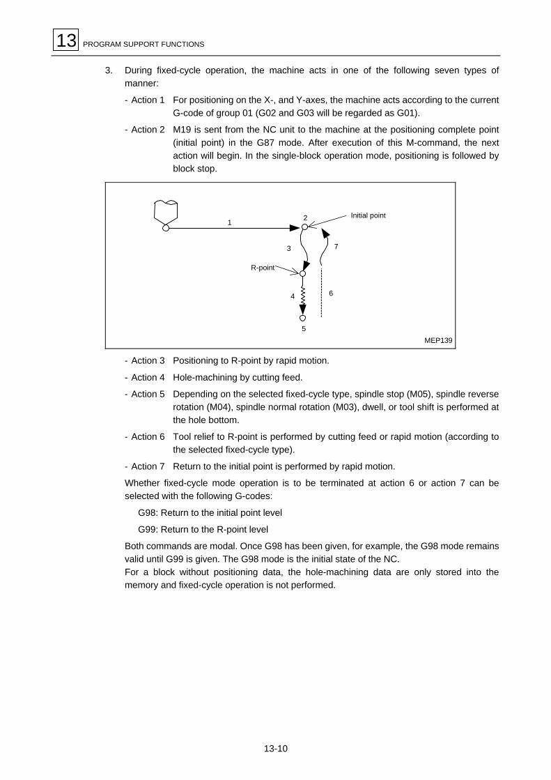
13 PROGRAM SUPPORT FUNCTIONS
13-10
3. During fixed-cycle operation, the machine acts in one of the following seven types ofmanner:
- Action 1 For positioning on the X-, and Y-axes, the machine acts according to the currentG-code of group 01 (G02 and G03 will be regarded as G01).
- Action 2 M19 is sent from the NC unit to the machine at the positioning complete point(initial point) in the G87 mode. After execution of this M-command, the nextaction will begin. In the single-block operation mode, positioning is followed byblock stop.
3 7
6
1
R-point
Initial point2
4
5MEP139
- Action 3 Positioning to R-point by rapid motion.
- Action 4 Hole-machining by cutting feed.
- Action 5 Depending on the selected fixed-cycle type, spindle stop (M05), spindle reverserotation (M04), spindle normal rotation (M03), dwell, or tool shift is performed atthe hole bottom.
- Action 6 Tool relief to R-point is performed by cutting feed or rapid motion (according tothe selected fixed-cycle type).
- Action 7 Return to the initial point is performed by rapid motion.
Whether fixed-cycle mode operation is to be terminated at action 6 or action 7 can beselected with the following G-codes:
G98: Return to the initial point level
G99: Return to the R-point level
Both commands are modal. Once G98 has been given, for example, the G98 mode remainsvalid until G99 is given. The G98 mode is the initial state of the NC.For a block without positioning data, the hole-machining data are only stored into thememory and fixed-cycle operation is not performed.

PROGRAM SUPPORT FUNCTIONS 13
13-11
13-2-3 G71.1 (Chamfering cutter CW)
G71.1 [Xx Yy] Rr Zz Qq0 [Pp0 Dd0] Ff0
d0G99
f0
G98
Initial point
R-point
Point D
Point Z
MEP140
5
q0
p0
32
1
4
q0 : Radiusp0 : Overlapping length (in arc)
d0 : Distance from R-pointf0 : Feed rate
- X, Y, P, and/or D can be omitted.
- Omission of Q or setting “Q0” results in a program error.

13 PROGRAM SUPPORT FUNCTIONS
13-12
13-2-4 G72.1 (Chamfering cutter CCW)
G72.1 [Xx Yy] Rr Zz Qq0 [Pp0 Dd0] Ff0
d0G99
f0
G98
Initial point
R-point
Point D
Point Z
MEP141
q0
p0
3 2
51
4
q0 : Radiusp0 : Overlapping length (in arc)
d0 : Distance from R-pointf0 : Feed rate
- X, Y, P, and/or D can be omitted.
- Omission of Q or setting “Q0” results in a program error.

PROGRAM SUPPORT FUNCTIONS 13
13-13
13-2-5 G73 (High-speed deep-hole drilling)
G73 [Xx Yy] Rr Zz Qtz [Ptc] Ff0 [Dd0 Kk0 Ii0 Jj0(Bb0)]
tz
tz + d0
f0
f0 d0
f1
[2]
[1]
i0
k0
G98
G99f2
f2
Point Z
Point D
R-point
Dwell (tc)
Initial point
Dwell (tc)
MEP142
tz : Depth of cut per passtc : Dwell (in time or No. of revolutions)d0 : Return distancek0 : Distance from R-point to the starting
point of cutting feedi0 : Feed override distance
j0 : Feed override ratio (%)(b0)f0 : Feed ratef1 : Feed overridden f1 = f0×j0(b0)/100f2 : Return speed (fixed)
Max. speed: 9999 mm/min (for mm-spec.)999.9 in./min (for in.-spec.)
- The feed rate will remain unchanged if either I or J(B) is omitted.
- X, Y, P, D, K, I, and/or J(B) can be omitted.If D is omitted or set to 0, the machine operates according to the value of parameter F12.
- The alarm 809 ILLEGAL NUMBER INPUT will occur if Q is set to 0.
- Whether argument J or B is to be used depends on the value that has been set in bit 1 ofparameter F84.
Parameter F84 bit 1 = 1: Argument J-command= 0: Argument B-command
Note: For a horizontal machining center, if the value of bit 1 of parameter F84 is 1(argument J-command), setting a B-command will cause the table to rotate. Becareful in that case to ensure no interference between the workpiece and the tool.
- The feed rate is f1 only if the starting point of a cutting pass is within the range of i0.
Example: In the diagram shown above, during the second cutting operation, since peckingreturn point [1] falls outside the range of feed override distance i0, feeding doesnot decelerate and cutting is performed at feed rate f0; during the third cuttingoperation, since pecking return point [2] falls within the range of i0, feedingdecelerates and cutting is performed at feed rate f1.

13 PROGRAM SUPPORT FUNCTIONS
13-14
13-2-6 G74 (Reverse tapping)
G74 [Xx Yy] Rr Zz [Ptc] Ff0 [Jj0(Bb0) Dd0 Hh0 Kk0]
G98
G99
M04
f1f1f0
d0
DwellM03
k0
Initial point
Point R’
R-point
Point Z
Point D
MEP143’
tc : Dwell (always in time)f0 : Feed ratej0 : 1…M03 after dwell at hole bottom(b0) 2…M03 before dwell at hole bottom
4…M04 after dwell at R-pointd0 : Distance from R-point
(Tap lifting distance)
h0 : Flag for synchronous/asynchronous tapping andthe return speed override (%) for synchronoustappingh0 = 0 Asynchronous tappingh0 > 0 Synchronous tapping
k0 : Distance from R-point
- X, Y, P, J(B), D, H, and/or K can be omitted.If, however, J(B) is omitted or set to 0, the setting of J(B) will be regarded as 2.If H is omitted, the selection between synchronous/asynchronous tapping is performed by thebit 6 of parameter F94.
- For synchronous tapping, see Subsection 13-2-21.
- Whether argument J or B is to be used depends on the value that has been set in bit 1 ofparameter F84.
Parameter F84 bit 1 = 1: Argument J-command= 0: Argument B-command
Note: For a horizontal machining center, if the value of bit 1 of parameter F84 is 1 (argumentJ-command), setting a B-command will cause the table to rotate. Be careful in thatcase to ensure no interference between the workpiece and the tool.

PROGRAM SUPPORT FUNCTIONS 13
13-15
13-2-7 G75 (Boring)
G75 [Xx Yy] Rr Zz [Ptc Qq0] Ff0 [Dd0 Jj0(Bb0) Kk0 Ii0]
Dwell
MEP144
d0
k0
G98
G99
q0
f0
i0
q0M03
M19q0
Initial point
R-point
Point D
Point Z
Feed and Spindle speed 70%
M03
tc : Dwell (in time or No. of revolutions)q0 : Amount of relief on the XY-plane
(Direction determined by bits 3 & 4 of I14)f0 : Feed rated0 : Distance from R-point
j0 : 0 or omitted・・・・・・・ M03 after machining(b0) Value except 0・・・・ M04 after machiningk0 : Distance from point Zi0 : Distance from point Z
- X, Y, P, Q, D, J(B), K, and/or I can be omitted.
- Whether argument J or B is to be used depends on the value that has been set in bit 1 ofparameter F84.
Parameter F84 bit 1 = 1: Argument J-command= 0: Argument B-command
Note: For a horizontal machining center, if the value of bit 1 of parameter F84 is 1 (argumentJ-command), setting a B-command will cause the table to rotate. Be careful in thatcase to ensure no interference between the workpiece and the tool.

13 PROGRAM SUPPORT FUNCTIONS
13-16
13-2-8 G76 (Boring)
G76 [Xx Yy] Rr Zz [Ptc Qq0] Ff1 [Dd0 Jj0(Bb0)]
MEP145
d0
G98
G99
q0
q0
f1
M03
M03q0
Initial point
R-point
Point D
Point Z
M19Dwell
tc : Dwell (in time or No. of revolutions)q0 : Amount of relief on the XY-plane
(Direction determined by bits 3 & 4 of I14)
f1 : Feed ratej0 : 0 or omitted ・・・・・・・M03 after machining(b0) Value except 0 ・・・・M04 after machining
- X, Y, P, Q, D, and/or J(B) can be omitted.
- Whether argument J or B is to be used depends on the value that has been set in bit 1 ofparameter F84.
Parameter F84 bit 1 = 1: Argument J-command= 0: Argument B-command
Note: For a horizontal machining center, if the value of bit 1 of parameter F84 is 1(argument J-command), setting a B-command will cause the table to rotate. Becareful in that case to ensure no interference between the workpiece and the tool.

PROGRAM SUPPORT FUNCTIONS 13
13-17
13-2-9 G77 (Back spot facing)
G77 [Xx Yy] Rr Zz [Ptc Qtz] Ff0 [Ef1 Jj0(Bb0) Dd0]
Dwell
MEP146’
f1
f1
f0 f0
M04M03
tz
d0
Initial point
Point R’
Point Z (z)
R-point (r)
(∗)
Point D
tc : Dwell (in time or No. of revolutions)tz : Distance from the initial pointf0 : Feed rate 0f1 : Feed rate 1
j0(b0) : Output order of M03 and M04 at hole bottom.0: M03, then M04 (for normal spindle rotation)1: M04, then M03 (for reverse spindle rotation)
d0 : Distance from point R’
- Normally, asynchronous feed (G94) is used for the pass marked with (∗). If f1 = 0, or if f1 isomitted, however, synchronous feed (G95) is used (feed rate = 0.5 mm/rev).
- X, Y, P, Q, E, J (B), and/or D can be omitted.
- Whether argument J or B is to be used depends on the value that has been set in bit 1 ofparameter F84.
Parameter F84 bit 1 = 1: Argument J-command= 0: Argument B-command
Note: For a horizontal machining center, if the value of bit 1 of parameter F84 is 1(argument J-command), setting a B-command will cause the table to rotate. Becareful in that case to ensure no interference between the workpiece and the tool.
- In G91 (incremental data input) mode, the direction of hole machining is automaticallydetermined according to the sign of Z data (the sign of data at address R will be ignored).

13 PROGRAM SUPPORT FUNCTIONS
13-18
13-2-10 G78 (Boring)
G78 [Xx Yy] Rr Zz [Ptc] Ff0 [Dd0 Kk0 Qi0]
MEP147
i0k0
G98
G99
f0
d0
Initial point
R-point
Point D
Point ZDwellM19
tc : Dwell (in time or No. of revolutions)d0 : Distance from R-point
k0 : Distance from point Zi0 : Distance from point Z
- X, Y, P, D, K, and/or Q can be omitted.

PROGRAM SUPPORT FUNCTIONS 13
13-19
13-2-11 G79 (Boring)
G79 [Xx Yy] Rr Zz [Ptc] Ff0 [Dd0 Kk0 Qi0 Ef1]
d0
i0k0
f1
G98
G99
f0
Initial point
R-point
Point Z
Dwell
Point D
MEP148
tc : Dwell (in time or No. of revolutions)f0 : Feed rate 0d0 : Distance from R-point
k0 : Distance from point Zi0 : Distance from point Zf1 : Feed rate 1
- Asynchronous feed is used for f1.If, however, f1 is set equal to 0 or is not set, then the tool is fed at the setting of f0.
- X, Y, P, D, K, Q, and/or E can be omitted.
13-2-12 G81 (Spot drilling)
G81 [Xx Yy] Rr Zz
G98
G99
Initial point
R-point
Point Z
MEP149
- X and/or Y can be omitted.

13 PROGRAM SUPPORT FUNCTIONS
13-20
13-2-13 G82 (Drilling)
G82 [Xx Yy] Rr Zz [Ptc] Ff0 [Dd0 Ii0 Jj0(Bb0)]
G98
G99
d0
i0
f0
f1
Initial point
R-point
Point D
Point ZDwell (tc) MEP150
tc : Dwell (in time or No. of revolutions)d0 : Distance from R-point to the starting
point of cutting feedi0 : Feed override distance
j0 : Feed override ratio (%)(b0)f0 : Feed ratef1 : Feed overridden f1 = f0×j0(b0)/100
- The feed rate will remain unchanged if either I or J(B) is omitted.
- X, Y, P, D, I, and/or J(B) can be omitted.
- Whether argument J or B is to be used depends on the value that has been set in bit 1 ofparameter F84.
Parameter F84 bit 1 = 1 : Argument J-command= 0 : Argument B-command
Note: For a horizontal machining center, if the value of bit 1 of parameter F84 is 1(argument J-command), setting a B-command will cause the table to rotate. Becareful in that case to ensure no interference between the workpiece and the tool.
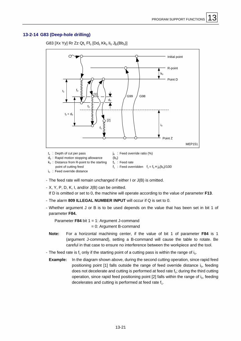
PROGRAM SUPPORT FUNCTIONS 13
13-21
13-2-14 G83 (Deep-hole drilling)
G83 [Xx Yy] Rr Zz Qtz Ff0 [Dd0 Kk0 Ii0 Jj0(Bb0)]
MEP151
k0
i0
G98G99d0
f0
f0
f1
tz + d0
tz
[2]
[1]
Initial point
R-point
Point D
Point Z
tz : Depth of cut per passd0 : Rapid motion stopping allowancek0 : Distance from R-point to the starting
point of cutting feedi0 : Feed override distance
j0 : Feed override ratio (%)(b0)f0 : Feed ratef1 : Feed overridden f1 = f0×j0(b0)/100
- The feed rate will remain unchanged if either I or J(B) is omitted.
- X, Y, P, D, K, I, and/or J(B) can be omitted.If D is omitted or set to 0, the machine will operate according to the value of parameter F13.
- The alarm 809 ILLEGAL NUMBER INPUT will occur if Q is set to 0.
- Whether argument J or B is to be used depends on the value that has been set in bit 1 ofparameter F84.
Parameter F84 bit 1 = 1: Argument J-command= 0: Argument B-command
Note: For a horizontal machining center, if the value of bit 1 of parameter F84 is 1(argument J-command), setting a B-command will cause the table to rotate. Becareful in that case to ensure no interference between the workpiece and the tool.
- The feed rate is f1 only if the starting point of a cutting pass is within the range of i0.
Example: In the diagram shown above, during the second cutting operation, since rapid feedpositioning point [1] falls outside the range of feed override distance i0, feedingdoes not decelerate and cutting is performed at feed rate f0; during the third cuttingoperation, since rapid feed positioning point [2] falls within the range of i0, feedingdecelerates and cutting is performed at feed rate f1.

13 PROGRAM SUPPORT FUNCTIONS
13-22
13-2-15 G84 (Tapping)
G84 [Xx Yy] Rr Zz [Ptc] Ff0 [Jj0(Bb0) Dd0 Hh0 Kk0]
MEP152’
G99 G98
d0
k0
Initial point
Point R’
R-point
Point D
Point Z
DwellM03
DwellM04
tc : Dwell (always in time)f0 : Feed ratej0 : 1…M04 after dwell at hole bottom(b0) 2…M04 before dwell at hole bottom
4…M03 after dwell at R-pointd0 : Distance from R-point
(Tap lifting distance)
h0 : Flag for synchronous/asynchronous tapping andthe return speed override (%) for synchronoustappingh0 = 0 Asynchronous tappingh0 > 0 Synchronous tapping
k0 : Distance from R-point
- X, Y, P, J(B), D, H, and/or K can be omitted.If, however, J(B) is omitted or set to 0, the setting of J(B) will be regarded as 2.If H is omitted, the selection between synchronous/asynchronous tapping is performed by thebit 6 of parameter F94.
- For synchronous tapping, see Subsection 13-2-21.
- Whether argument J or B is to be used depends on the value that has been set in bit 1 ofparameter F84.
Parameter F84 bit 1 = 1 : Argument J-command= 0 : Argument B-command
Note: For a horizontal machining center, if the value of bit 1 of parameter F84 is 1 (argumentJ-command), setting a B-command will cause the table to rotate. Be careful in thatcase to ensure no interference between the workpiece and the tool.

PROGRAM SUPPORT FUNCTIONS 13
13-23
13-2-16 G85 (Reaming)
G85 [Xx Yy] Rr Zz [Ptz] Ff0 [Ef1 Dd0]
Dwell MEP153
G99
f1
f0
d0
G98
Initial point
R-point
Point Z
tz : Dwell (in time or No. of revolutions)f0 : Feed rate 0
f1 : Feed rate 1d0 : Distance from R-point
- Asynchronous feed is used for f1.If, however, f1 is set equal to 0 or is not set, then the tool is fed at the setting of f0.
- X, Y, P, E, and/or D can be omitted.
13-2-17 G86 (Boring)
G86 [Xx Yy] Rr Zz [Ptc]
Initial point
R-point
Point ZDwell
G99
G98
M03
M05 MEP154
tc : Dwell (in time or No. of revolutions)
- X, Y, and/or P can be omitted.

13 PROGRAM SUPPORT FUNCTIONS
13-24
13-2-18 G87 (Back boring)
G87 [Xx Yy] Rr Zz [Ptc Qq0] Ff0 [Dd0 Jj0(Bb0)]
M19
M03q0
M19
M03
d0
Initial point
Point Z
R-point
MEP155
Dwell
tc : Dwell (in time or No. of revolutions)q0 : Amount of relief on the XY-plane
(Direction determined by bits 3 & 4 of I14)f0 : Feed rate
d0 : Distance from point Zj0 : 0 or omitted・・・・・・・ M03 at R-point(b0) Value except 0・・・・ M04 at R-point
- X, Y, P, Q, D, and/or J(B) can be omitted.
- Initial-point return is always used for G87 (even if the current modal is of G99).
- Whether argument J or B is to be used depends on the value that has been set in bit 1 ofparameter F84.
Parameter F84 bit 1 = 1: Argument J-command= 0: Argument B-command
Note: For a horizontal machining center, if the value of bit 1 of parameter F84 is 1(argument J-command), setting a B-command will cause the table to rotate. Becareful in that case to ensure no interference between the workpiece and the tool.
- In G91 (incremental data input) mode, the direction of hole machining is automaticallydetermined according to the sign of Z data (the sign of data at address R will be ignored).

PROGRAM SUPPORT FUNCTIONS 13
13-25
13-2-19 G88 (Boring)
G88 [Xx Yy] Rr Zz [Ptc]
MEP156
G99
G98
Initial point
R-point
Point ZDwell, M05, M00
tc : Dwell (in time or No. of revolutions)
- X, Y, and/or P can be omitted.
- At the hole bottom, M05 and M00 are outputted.
13-2-20 G89 (Boring)
G89 [Xx Yy] Rr Zz [Ptc]
G98
G99
Initial point
Dwell
R-point
Point Z
MEP157
tc : Dwell (in time or No. of revolutions)
- X, Y, and/or P can be omitted.

13 PROGRAM SUPPORT FUNCTIONS
13-26
13-2-21 Synchronous tapping (Option)
In an EIA/ISO program, synchronous tapping can be selected by additionally setting data at theaddress H in the tapping cycle block of G74 or G84. Address H is used to select asynchronous/asynchronous tapping and to designate the override of return speed. Specialpreparatory functions G84.2 and G84.3 are also provided for both types of synchronous tapping.
1. G74 [Reverse tapping]
G74 [Xx Yy] Rr Zz [Ptc] Ff0 [Jj0(Bb0) Dd0 Hh0 Kk0]
G98
G99
M04
f1f1f0
d0
k0
Initial point
Point R’
R-point
Point Z
Point D
Spindle stop
DwellM03
MEP143’
tc : Dwell (always in time)f0 : Feed rate
(Set the pitch for synchronous tapping)j0 : 1…M03 after dwell at hole bottom(b0) 2…M03 before dwell at hole bottom
4…M04 after dwell at R-point
d0 : Distance from R-point (Tap lifting distance)h0 : Return speed override (%)
h0 = 0 .....Asynchronous tappingh0 ≥ 1 ....Synchronous tapping
k0 : Distance from R-point
- X, Y, P, J(B), D, H, and/or K can be omitted.If, however, J(B) is omitted or set to 0, the setting of J(B) will be regarded as 2.If H is omitted, the selection between synchronous/asynchronous tapping is performed by thebit 6 of parameter F94.
- H is used to select whether synchronous tapping cycle operation or asynchronous tappingcycle operation is to be performed using a machine capable of synchronous tapping. This codeis also used to override the return speed for synchronous tapping cycle operation. H becomesinvalid for a machine not capable of synchronous tapping, or if your machine has synchronoustapping function but bit 6 of parameter F94 is not set to 1.
- Whether argument J or B is to be used depends on the value that has been set in bit 1 ofparameter F84.
Parameter F84 bit 1 = 1: Argument J-command= 0: Argument B-command
Note: For a horizontal machining center, if the value of bit 1 of parameter F84 is 1(argument J-command), setting a B-command will cause the table to rotate. Becareful in that case to ensure no interference between the workpiece and the tool.
- During gear selection for tapping, due consideration must be given to ensure the minimumspindle acceleration/deceleration time. Refer to the machine-operating manual.

PROGRAM SUPPORT FUNCTIONS 13
13-27
2. G84 (Normal tapping)
G84 [Xx Yy] Rr Zz [Ptc] Ff0 [Jj0(Bb0) Dd0 Hh0 Kk0]
G99 G98
d0
k0
Initial point
Point R’
R-point
Point Z
Point D
DwellM03
Spindle stop
DwellM04 MEP152’
tc : Dwell (always in time)f0 : Feed rate
(Set the pitch for synchronous tapping)j0 : 1…M04 after dwell at hole bottom(b0) 2…M04 before dwell at hole bottom
4…M03 after dwell at R-point
d0 : Distance from R-point (Tap lifting distance)h0 : Return speed override (%)
h0 = 0 .....Asynchronous tappingh0 ≥ 1 ....Synchronous tapping
k0 : Distance from R-point
- X, Y, P, J(B), D, H, and/or K can be omitted.If, however, J(B) is omitted or set to 0, the setting of J(B) will be regarded as 2.If H is omitted, the selection between synchronous/asynchronous tapping is performed by thebit 6 of parameter F94.
- H is used to select whether synchronous tapping cycle operation or asynchronous tappingcycle operation is to be performed using a machine capable of synchronous tapping. This codeis also used to override the return speed for synchronous tapping cycle operation. H becomesinvalid for a machine not capable of synchronous tapping, or if your machine has synchronoustapping function but bit 6 of parameter F94 is not set to 1.
- Whether argument J or B is to be used depends on the value that has been set in bit 1 ofparameter F84.
Parameter F84 bit 1 = 1: Argument J-command= 0: Argument B-command
Note: For a horizontal machining center, if the value of bit 1 of parameter F84 is 1(argument J-command), setting a B-command will cause the table to rotate. Becareful in that case to ensure no interference between the workpiece and the tool.
- During gear selection for tapping, due consideration must be given to ensure the minimumspindle acceleration/deceleration time. Refer to the machine-operating manual.

13 PROGRAM SUPPORT FUNCTIONS
13-28
3. G84.2 (Normal tapping)
G84.2 [Xx Yy] Rr Zz [Ptc] Ff0
f0 f0 f0
G98
G99
Initial point
R-point
Point ZDwellM04
Spindle stop
tc : Dwell (in time) at point Z and upon return to R-pointf0 : Feed rate (in pitch)
- X, Y, and/or P can be omitted.
- G84.2 and G84.3 always performs a synchronous tapping, irrespective of the setting in bit 6 ofparameter F94.
- Designation of G84.2 or G84.3 without the corresponding option would cause the alarm No.952 NO SYNCHRONIZED TAP OPTION.
- During gear selection for tapping, due consideration must be given to ensure the minimumspindle acceleration/deceleration time. Refer to the machine-operating manual.
- The value of parameter K90 is always referred to as the return speed override (%).

PROGRAM SUPPORT FUNCTIONS 13
13-29
4. G84.3 (Reverse tapping)
G84.3 [Xx Yy] Rr Zz [Ptc] Ff0
f0 f0 f0
G98
G99
Initial point
R-point
Point ZDwellM03
Spindle stop
tc : Dwell (in time) at point Z and upon return to R-pointf0 : Feed rate (in pitch)
- X, Y, and/or P can be omitted.
- G84.2 and G84.3 always performs a synchronous tapping, irrespective of the setting in bit 6 ofparameter F94.
- Designation of G84.2 or G84.3 without the corresponding option would cause the alarm No.952 NO SYNCHRONIZED TAP OPTION.
- During gear selection for tapping, due consideration must be given to ensure the minimumspindle acceleration/deceleration time. Refer to the machine-operating manual.
- The value of parameter K90 is always referred to as the return speed override (%).

13 PROGRAM SUPPORT FUNCTIONS
13-30
13-3 Initial Point and R-Point Level Return: G98 and G99
1. Function and purpose
Commands G98 or G99 can be used to select whether the return level of the final sequenceduring fixed-cycle operation is to be set at R-point or at the initial point of machining.
2. Programming format
G98: Initial point level return
G99: R-point level return
3. Detailed description
The following represents the relationship between the G98/G99 mode and repeat times:
Numberof holes
Sample programG98
(At power-on or after cancellationusing M02, M30, or RESET key)
G99
Onlyone
G81 X100. Y100.Z–50. R25. F1000
Initial point
R-point
Return to initial point level.
Initial point
R-point
Return to R-point level.
Two ormore
G81 X100. Y100.Z–50. R25. L5 F1000
Last hole2nd hole1st hole
≈
Always return to initial point.
Last hole2nd hole1st hole
≈
MEP158

PROGRAM SUPPORT FUNCTIONS 13
13-31
13-4 Scaling ON/OFF: G51/G50
1. Function and purpose
The shape specified in a machining program can be enlarged or reduced in size using scalingcommand G51. The range of scaling (enlargement/reduction) factors is from 0.000001 to99.999999.Use command G51 to specify a scaling axis, the center of scaling, and a scaling factor.Use command G50 to specify scaling cancellation.
2. Programming format
G51 Xx Yy Zz Pp Scaling on (specify a scaling axis, the center of scaling(incremental/absolute), and a scaling factor)
G50 Scaling cancel
3. Detailed description
A. Specifying a scaling axis
The scaling mode is set automatically by setting G51. Command G51 does not move any axis; itonly specifies a scaling axis, the center of scaling, and a scaling factor.Scaling becomes valid only for the axis to which the center of scaling has been specified.
Center of scalingThe center of scaling must be specified with the axis address according to the absolute orincremental data command mode (G90 or G91). This also applies even when specifying thecurrent position as the center.
Scaling factorUse address P to specify a scaling factor.
Minimum unit of specification: 0.000001
Specifiable range of factors: 1 to 99999999 or 0.000001 to 99.999999 (times)(Although both are valid, the latter with a decimal point must bepreceded by G51.)
Scaling center
Programmed shape
Machining shape
b
a
Scaling factor: b/a
MEP177

13 PROGRAM SUPPORT FUNCTIONS
13-32
The scaling factor set in parameter F20 will be used if you do not specify any scaling factor in thesame block as that of G51. The current setting of this parameter will be used if it is updatedduring the scaling mode. That is, the parameter setting existing when G51 is set is valid.Data will be calculated at a scaling factor of 1 if neither the program nor the parameter has aspecified scaling factor.
Program errors occur in the following cases:
- If scaling is specified for a machine not capable of scaling (Alarm 872 G51 OPTION NOTFOUND)
- If a scaling factor exceeding its maximum available value is specified in the same block as thatof G51 (Alarm 809 ILLEGAL NUMBER INPUT) (All scaling factors less than 0.000001 areprocessed as 1.)
B. Cancellation of scaling
The scaling cancel mode is set automatically by setting G50. Setting this command code offsetsany deviation between the program coordinates and the coordinates of the actual machineposition. Even for axes that have not been designated in the same block as that of G50, themachine moves through the offset amount specified by scaling.
4. Precautions
1. Scaling does not become valid for tool diameter offsetting, tool length offsetting, or toolposition offsetting. Offsets and other corrections are calculated only for the shape existingafter scaling.
2. Scaling is valid only for move commands associated with automatic operation (tape,memory, or MDI); it is not valid for manual movement.
3. After-scaling coordinates are displayed as position data.
4. Scaling is performed on the axis for which the center of scaling is specified by G51. In thatcase, scaling becomes valid for all move commands associated with automatic operation,as well as for the parameter-set return strokes of G73 and G83 and for the shift strokes ofG76 and G87.
5. If only one axis of the plane concerned is selected for scaling, circular interpolation isperformed with the single scaling on that axis.
6. Scaling will be cancelled if either M02, M30, or M00 (only when M0 contains reset) is issuedduring the scaling mode. Scaling is also cancelled by an external reset command or anyother reset functions during the reset/initial status.
7. Data P, which specifies a scaling factor, can use a decimal point. The decimal point,however, becomes valid only if scaling command code G51 precedes data P.
G51P0.5 0.5 timeP0.5G51 1 time (regarded as P = 0)P500000G51 0.5 timeG51P500000 0.5 time
8. The center of scaling is shifted accordingly if the coordinate system is shifted usingcommands G92 or G52 during scaling.

PROGRAM SUPPORT FUNCTIONS 13
13-33
5. Sample programs
1. Basic operation I
N01 G92X0Y0Z0N02 G90G51X–100.Y–100.P0.5N03 G00G43Z–200.H02N04 G41X–50.Y-50.D01N05 G01Z–250.F1000N06 Y–150.F200N07 X–150.N08 G02Y–50.J50.N09 G01X–50.N10 G00Z0N11 G40G50X0Y0N12 M02
–200. –150. –100. –50.
–50.
–100.
–150.
Tool path after 1/2 scalingProgram path after 1/2 scalingTool path without scalingProgram path without scaling
D01 = 25.000M: Scaling center
XW
Y
N09 N11N04
N06
N07
MN08
MEP178

13 PROGRAM SUPPORT FUNCTIONS
13-34
2. Basic operation II
N01 G92X0Y0N02 G90G51P0.5 .................. See [1] to [4] below.N03 G00X–50.Y–50.N04 G01X–150.F1000N05 Y–150.N06 X–50.N07 Y–50.N08 G00G50N09 M02
[1] Without scaling N02 G90G51P0.5[2] If scaling is to be done for X, Y N02 G90G51X–100.Y–100.P0.5[3] If scaling is to be done for X only N02 G90G51X–100.P0.5[4] If scaling is to be done for Y only N02 G90G51Y–100.P0.5
[3]
[4]
[2]
[1]
–150. –100. –50.Y
M
X
–50.
–100.
–150.
W
MEP179

PROGRAM SUPPORT FUNCTIONS 13
13-35
3. Basic operation III
N01 G92X0Y0N02 G90G51P0.5 .................. See [1] to [4] below.N03 G00X–50.Y–50.N04 G01Y–150.F1000N05 G02X–100.I–25.N06 G01X–150.N07 G02X–200.I–25.N08 G01X–250.Y–100.N09 Y–50.N10 X–50.N11 G00G50N12 M02
[1] Without scaling N02 G90G51P0.5[2] If scaling is to be done for X, Y N02 G90G51X–125.Y–100.P0.5[3] If scaling is to be done for X only N02 G90G51X–125.P0.5[4] If scaling is to be done for Y only N02 G90G51Y–100.P0.5
–250. –200. –150. –100. –50.
–50.
–100.
–150.
–125.
Y
X
M
W
[1]
[4]
[3]
[2]
MEP180

13 PROGRAM SUPPORT FUNCTIONS
13-36
4. Reference-point (zero point) check (G27) during scaling
Setting G27 during scaling cancels the scaling mode after G27 has been executed.
N01 G28X0Y0N02 G92X0Y0N03 G90G51X–100.Y–100.P0.5N04 G00X–50.Y–50.N05 G01X–150.F1000N06 G27X0Y0
M
If a program is constructed in the manner that the reference point is reached under normalmode, it will also be reached even under scaling mode.
–150. –100. –50.
–50.
–100.
X
Y
N06*
N06**
N04
N05
W
MN06**............ During scalingN06* ............. Without scaling
MEP181

PROGRAM SUPPORT FUNCTIONS 13
13-37
5. Reference-point (zero point) return (G28, G29, or G30) during scaling
Setting G28 or G30 during scaling cancels the scaling mode at the middle point and thenexecutes the reference-point (zero point) return command. If the middle point has not beenset, the reference-point (zero point) return command is executed with the point wherescaling has been cancelled as middle point.If G29 is set during the scaling mode, scaling will be performed for the entire movementafter the middle point.
N01 G28X0Y0N02 G92X0Y0N03 G90G51X–100.Y–150.P500000N04 G00X–50.Y–100. 0.5N05 G01X–150.F1000N06 G28X–100.Y–50.N07 G29X–50.Y–100.
MEP182
–150. –100. –50.
–50.
–100.
X
Y
N06*
N06**
M
N04
N05
–150.N06*N07*
Without scaling
During scaling
Intermediate point
N06**N07**
N07**
N07*
N07
N06
W

13 PROGRAM SUPPORT FUNCTIONS
13-38
6. One-way positioning (G60) during scaling
Setting G60 during the scaling mode executes scaling at the final point of positioning, andthus no scaling is performed for the parameter l1 of creeping. That is, the amount ofcreeping remains constant, irrespective of whether scaling is valid.
N01 G92X0Y0N02 G91G51X–100.Y–150.P0.5N03 G60X–50.Y–50.N04 G60X–150.Y–100.
–150. –100. –50.
–50.
–100.
X
Y
N04
N03
–150.
W
Without scaling
During scaling
M
MEP183
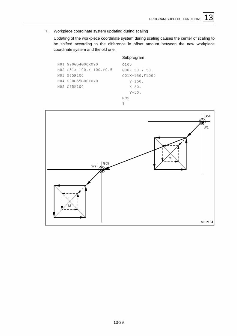
PROGRAM SUPPORT FUNCTIONS 13
13-39
7. Workpiece coordinate system updating during scaling
Updating of the workpiece coordinate system during scaling causes the center of scaling tobe shifted according to the difference in offset amount between the new workpiececoordinate system and the old one.
N01 G90G54G00X0Y0N02 G51X–100.Y–100.P0.5N03 G65P100N04 G90G55G00X0Y0N05 G65P100
Subprogram
O100G00X–50.Y–50.G01X–150.F1000
Y–150.X–50.Y–50.
M99%
W1
M
M’
W2G55
G54
MEP184

13 PROGRAM SUPPORT FUNCTIONS
13-40
8. Figure rotation during scaling
Setting a figure rotate command during scaling executes scaling for both the center andradius of rotation of the figure.
N01 G92X0Y0N02 G90G51X0Y0P0.5N03 G00X–100.Y–100.N04 M98P200I–50.L8
Subprogram
O200G91G01X–14.645Y35.355F1000M99%
MEP185
X–150. –100. –50.
–50.
–100.
Y
–150.
W
–200.
After scaling
Machining program
Scaling center

PROGRAM SUPPORT FUNCTIONS 13
13-41
9. Scaling using a figure rotation subprogram
Setting a scaling command in a figure rotation subprogram executes scaling only for theshape predefined in the subprogram. Scaling is not executed for the radius of rotation of thefigure.
G92X0Y0G90G00X100.M98P300I–100.L4G90G00X0Y0M02
Subprogram
O300G91G51X0Y0P0.5G00X–40.G01Y–40.F1000
X40.G03Y80.J40.G01X–40.
Y–40.G00G50X40.
X–100.Y100.M99%
W
Machining program
After scaling
MEP186

13 PROGRAM SUPPORT FUNCTIONS
13-42
10. Scaling during coordinate rotation
If scaling during coordinate rotation is programmed the center of scaling will rotate andscaling will be performed at that rotated center of scaling.
N01 G92X0Y0N02 M00 (Coordinate rotation data setting)N03 G90G51X–150.Y–75.P0.5N04 G00X–100.Y–50,N05 G01X–200.F1000N06 Y–100.N07 X–100.N08 Y–50.N09 G00G50X0Y0
–150. –100. –50.
–50.
–100.
X
Y
–150.
W
–200.
Shift of scaling centerby coordinate rotation
Machining program
N04
N08N05
N06N07
Scaling only
Coordinate rotation only
Coordinate rotation and scaling
MEP187

PROGRAM SUPPORT FUNCTIONS 13
13-43
11. Setting G51 during scaling
If command G51 is set during the scaling mode, the axis for which the center of scaling isnewly specified will also undergo scaling. The scaling factor specified by the latest G51command becomes valid in that case.
N01 G92X0Y0N02 G90G51X–150.P0.75 Scaling axis X; P = 0.75N03 G00X–50.Y–25.N04 G01X–250.F1000N05 Y–225.N06 X–50.N07 Y–25.N08 G51Y–125.P0.5 Scaling axes X and Y; P = 0.5N09 G00X–100.Y–75.N10 G01X–200.N11 Y–175.N12 X–100.N13 Y–75.N14 G00G50X0Y0 Cancel
–150. –100. –50.
–50.
X
Y
W
–200.
–100.
–150.
–250.
–200.
N03N14
N09
N04
N05
N11
N12
N06
N07
N13
N10
Machiningprogram
MEP188

13 PROGRAM SUPPORT FUNCTIONS
13-44
13-5 Mirror Image ON/OFF: G51.1/G50.1
1. Function and purpose
Mirror image mode can be turned on and off for each axis using G-codes. Higher priority is givento the mirror image setting with the G-codes over setting by any other methods.
2. Programming format
G51.1 Xx1 Yy1 Zz1 Mirror image OnG50.1 Xx2 Yy2 Zz2 Mirror image Off
3. Detailed description
- Use the address and coordinates in a G51.1 block to specify the mirroring axis and mirroringcenter (using absolute or incremental data), respectively.
- If the coordinate word is designated in G50.1, then this denotes the axis for which the mirrorimage is to be cancelled. Coordinate data, even if specified, is ignored in that case.
- After mirror image processing has been performed for only one of the axes forming a plane, therotational direction and the offset direction become reverse during arc interpolation, tooldiameter offsetting, or coordinate rotation.
- Since the mirror image processing function is valid only for local coordinate systems, the centerof mirror image processing moves according to the particular counter preset data or workpiececoordinate offsetting data.
4. Sample programs
MEP189
Y
X
[1]
[4][3]
[2]
(Main program)G00G90G40G49G80M98P100G51.1X0M98P100G51.1Y0M98P100G50.1X0M98P100G50.1Y0M30
X Y
[1] OFF OFF[2] ON OFF
[3] ON ON
[4] OFF OFFOFF OFF
(Subprogram O100)G91G28X0Y0G90G00X20.Y20.G42G01X40.D01F120Y40.X20.Y20.G40X0Y0M99

PROGRAM SUPPORT FUNCTIONS 13
13-45
13-6 Subprogram Control: M98, M99
1. Function and purpose
Fixed sequences or repeatedly used programs can be stored in the memory as subprogramswhich can then be called from the main program when required. M98 serves to call subprogramsand M99 serves to return from the subprogram. Furthermore, it is possible to call othersubprograms from particular subprograms and the nesting depth can include as many as 8levels.
TEP161
Sub program Sub programSub programSub programMain program
O5000;
M99;
(Level 8)(Level 3)(Level 2)(Level 1)
Nesting depth
O0010;
M98P1000;
M02;
O1000;
M98P1200 Q20;
M99;
O1200;
N20;M98P2000;
N60;M99;
O2000;
M98P2500;
M99P60;
The table below shows the functions which can be executed by adding and combining the tapestoring and editing functions, subprogram control functions and fixed cycle functions.
Case 1 Case 2 Case 3 Case 4
1. Tape storing and editing2. Subprogram control3. Fixed cycles
YesNoNo
YesYesNo
YesYesYes
YesNoYes
Function
1. Memory operation " " " "
2. Tape editing (main memory) " " " "
3. Subprogram call × " " ×
4. Subprogram nesting level call (Note 2) × " " ×
5. Fixed cycles × × " "
6. Fixed cycle subprogram editing × × " "
Notes:1. “"” denotes a function which can be used and “×” a function which cannot be used.2. The nesting depth can include as many as 8 levels.

13 PROGRAM SUPPORT FUNCTIONS
13-46
2. Programming format
Subprogram call
M98 P_ Q_ L_;Number of subprogram repetitions (L1 if omitted)
Sequence number in subprogram to be called (head block if omitted)
Program number of subprogram to be called (own program if omitted).P can only be omitted during memory operation.
Return to main program from subprogram
M99 P_ L_;Number of times after repetition number has been changed
Sequence number of return destination (returned to block following block of call if omitted)
3. Creating and entering subprograms
Subprograms have the same format as machining programs for normal memory operationexcept that the subprogram completion instruction M99 (P_ L_) is entered as an independentblock at the last block.
O∆∆∆∆ ; Program number as subprogram...............;...............; M Main body of subprogram...............; M99; Subprogram return command%(EOR) End of record code (% with ISO code and EOR with EIA code)
The above program is registered by editing operations. For further details, refer to the section onprogram editing.Only those subprograms numbers ranging from 1 through 9999 designated by the optionalspecifications can be used. When there are no program numbers on the tape, the setting numberfor “program input” is used.Up to 8 nesting levels can be used for calling programs from subprograms, and program erroroccurs if this number is exceeded.Main programs and subprograms are registered in order in which they were read because nodistinction is made between them. This means that main programs and subprograms should notbe given the same numbers. (If the same numbers are given, error occurs during entry.)

PROGRAM SUPPORT FUNCTIONS 13
13-47
Example: ;O"""" ;.................; Subprogram A MM99; %
;O∆∆∆∆ ;.................; Subprogram B MM99; %
;O#### ;.................; Subprogram C MM99; %
Note 1: Main programs can be used during memory and tape operation but subprograms musthave been entered in the memory.
Note 2: The following commands are not the object of subprogram nesting and can be calledeven beyond the 8th nesting level.- Fixed cycles- Pattern cycles
4. Subprogram execution
M98: Subprogram call commandM99: Subprogram return command
Programming format
M98 P_ Q_ L_;
Where P : Number of the subprogram to be called (up to 8 digits)Q : Any sequence number within the subprogram to be called (up to 5 digits)L : Number of repetitions from 1 to 9999 with numerical value of four figures; if L is
omitted, the subprogram is executed once ; with L0, there is no execution.For example,M98 P1 L3; is equivalent to the following :M98 P1;M98 P1;M98 P1;

13 PROGRAM SUPPORT FUNCTIONS
13-48
Example 1: When there are 3 subprogram calls (known as 3 nesting levels)
TEP162
Main program
M98P1;
M02;
Subprogram 1
O1;
M98P10;
M99;
Subprogram 2
O10;
M98P20;
M99;
Subprogram 3
O20;
M99;
[1]
[1]’
[2]
[2]’
[3]
[3]’
Sequence of execution: [1]→[2]→[3]→[3]’→[2]’→[1]’
For nesting, the M98 and M99 commands should always be paired off on a 1 : 1 basis [1]' for [1],[2]' for [2], etc.Modal information is rewritten according to the execution sequence without distinction betweenmain programs and subprograms. This means that after calling a subprogram, attention must bepaid to the modal data status when programming.
Example 2: The M98 Q_ ; and M99 P_ ; commands designate the sequence numbers in aprogram with a call instruction.
TEP163
M98Q3;
N3__;
M99;
M98Q_;
N100__;M98P123;N200__;N300__;N400__; M M
M99P_;
O123;
M99P100;
Search

PROGRAM SUPPORT FUNCTIONS 13
13-49
Example 3: Main program M98 P2 ;O1; M Subprogram 1M99;%O2; MN200 Subprogram 2 MM99;%O3; MN200 Subprogram 3 MM99;%
- When the O2 N200 block is searched with the memory search function, the modal data areupdated according to the related data of O2 to N200.
- The same sequence number can be used in different subprograms.
- When the subprogram (No. p1) is to be repeatedly used, it will be repeatedly executed for I1
times provided that M98 Pp1 Ll1 ; is programmed.
5. Other precautions
- Programming error occurs when the designated program number (P) is not found.
- Single block stop does not occur in the M98P _ ; and M99 ; block. If any address except O, N, P,Q or L is used, single block stop can be executed. (With X100. M98 P100 ; operation branchesto O100 after X100. is executed.)
- When M99 is commanded in the main program, operation returns to the head.
- Operation can branch from tape or PTR operation to a subprogram by M98P_ but thesequence number of the return destination cannot be designated with M99P_ ;. (P_ is ignored.)
- Care should be taken that the search operation will take time when the sequence number isdesignated by M99P_ ;
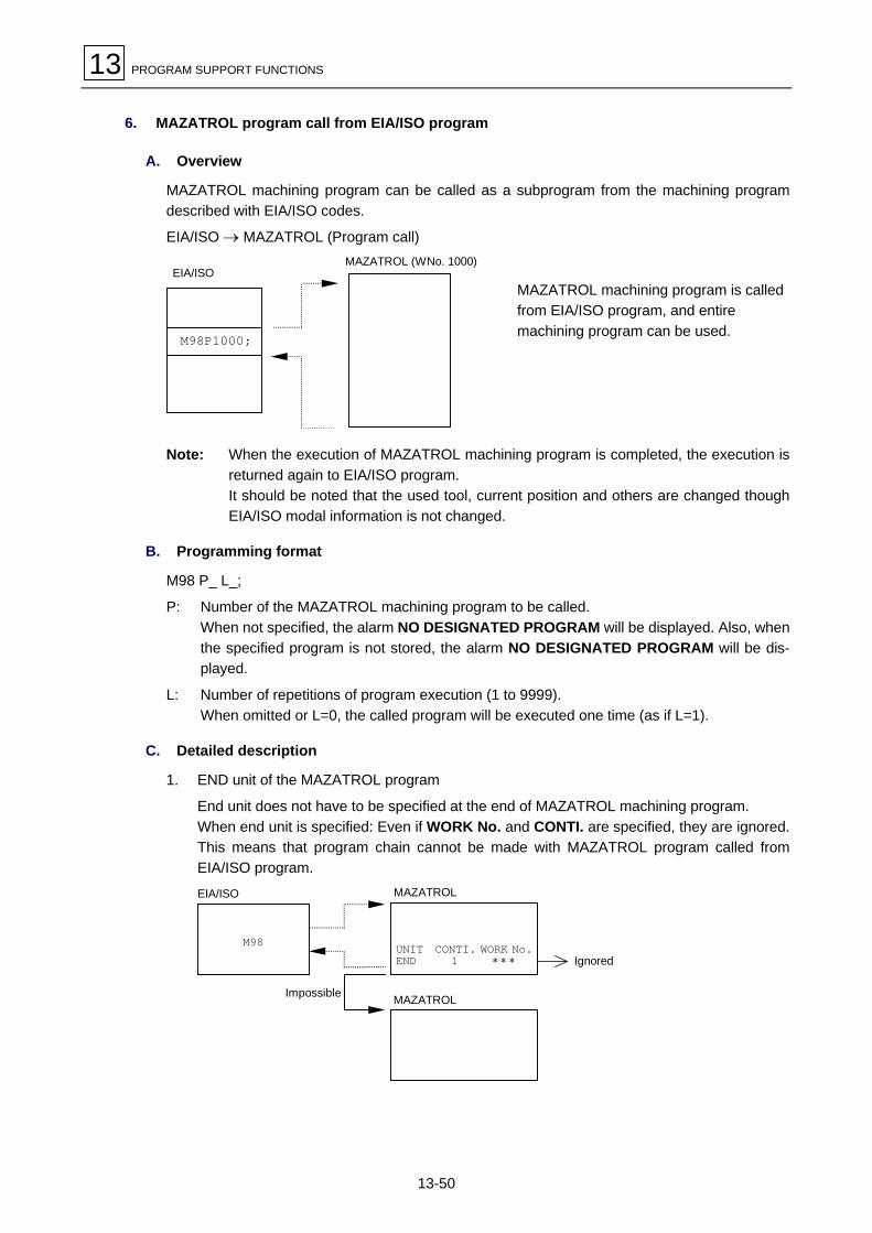
13 PROGRAM SUPPORT FUNCTIONS
13-50
6. MAZATROL program call from EIA/ISO program
A. Overview
MAZATROL machining program can be called as a subprogram from the machining programdescribed with EIA/ISO codes.
EIA/ISO → MAZATROL (Program call)
M98P1000;
EIA/ISOMAZATROL (WNo. 1000)
MAZATROL machining program is calledfrom EIA/ISO program, and entiremachining program can be used.
Note: When the execution of MAZATROL machining program is completed, the execution isreturned again to EIA/ISO program.It should be noted that the used tool, current position and others are changed thoughEIA/ISO modal information is not changed.
B. Programming format
M98 P_ L_;
P: Number of the MAZATROL machining program to be called.When not specified, the alarm NO DESIGNATED PROGRAM will be displayed. Also, whenthe specified program is not stored, the alarm NO DESIGNATED PROGRAM will be dis-played.
L: Number of repetitions of program execution (1 to 9999).When omitted or L=0, the called program will be executed one time (as if L=1).
C. Detailed description
1. END unit of the MAZATROL program
End unit does not have to be specified at the end of MAZATROL machining program.When end unit is specified: Even if WORK No. and CONTI. are specified, they are ignored.This means that program chain cannot be made with MAZATROL program called fromEIA/ISO program.
M98 UNIT CONTI. WORK No.END 1 ∗ ∗ ∗ Ignored
MAZATROL
MAZATROLEIA/ISO
Impossible

PROGRAM SUPPORT FUNCTIONS 13
13-51
2. MAZATROL program executionWhen MAZATROL program is called from EIA/ISO program, the MAZATROL program isexecuted like automatic operation of MAZATROL.MAZATROL program is executed independently of EIA/ISO program which has made thecall. In other words, it performs the same machining as MAZATROL program alone isexecuted. When calling MAZATROL program, always place a tool outside the safety profilebeforehand. Failure to do this may cause interference of a workpiece with the tool.
3. NestingWithin a MAZATROL program called from EIA/ISO program, the subprogram unit (SUBPRO) cannot be used.
M98; SUB PRO
END
MAZATROLEIA/ISO
Call
Impossible
EIA/ISO
Refer to the MAZATROL Programming Manual for SUB PRO unit.
Note: As is the case with a SUB PRO unit, alarm SUB PROGRAM NESTING OVER willoccur if a point-machining unit is present in the MAZATROL program that hasbeen called up as a subprogram from the EIA program.
D. Remarks
1. MDI interruption and macro interruption signal during MAZATROL program execution areignored.
2. MAZATROL program cannot be restarted halfway.
3. MAZATROL program call in the mode of a fixed cycle results in an alarm.
4. MAZATROL program call in the mode of tool radius compensation results in an alarm.
5. MAZATROL program call is not available in the MDI operation mode (results in an alarm).
6. A MAZATROL program called by M98 cannot be executed but in its entirety (from the headto the end).
7. Commands to addresses other than O, N, P, Q, L and H in a block of M98 for MAZATROLprogram call will not be processed till completion of the called program.
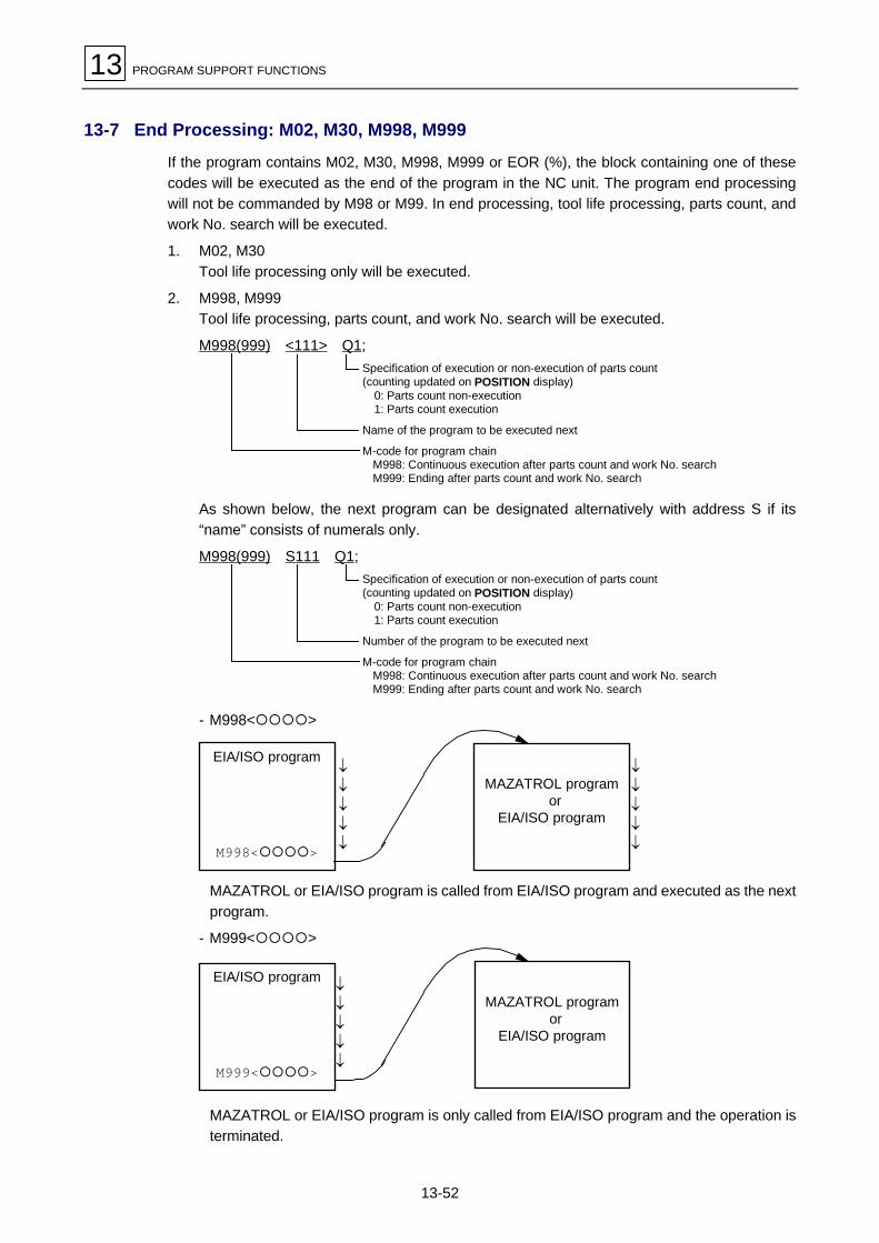
13 PROGRAM SUPPORT FUNCTIONS
13-52
13-7 End Processing: M02, M30, M998, M999
If the program contains M02, M30, M998, M999 or EOR (%), the block containing one of thesecodes will be executed as the end of the program in the NC unit. The program end processingwill not be commanded by M98 or M99. In end processing, tool life processing, parts count, andwork No. search will be executed.
1. M02, M30Tool life processing only will be executed.
2. M998, M999Tool life processing, parts count, and work No. search will be executed.
M998(999) <111> Q1;Specification of execution or non-execution of parts count(counting updated on POSITION display)
0: Parts count non-execution1: Parts count execution
Name of the program to be executed next
M-code for program chainM998: Continuous execution after parts count and work No. searchM999: Ending after parts count and work No. search
As shown below, the next program can be designated alternatively with address S if its“name” consists of numerals only.
M998(999) S111 Q1;Specification of execution or non-execution of parts count(counting updated on POSITION display)
0: Parts count non-execution1: Parts count execution
Number of the program to be executed next
M-code for program chainM998: Continuous execution after parts count and work No. searchM999: Ending after parts count and work No. search
- M998<"""">
↓↓↓↓↓
↓↓↓↓↓
EIA/ISO program
M998<"""">
MAZATROL program or
EIA/ISO program
MAZATROL or EIA/ISO program is called from EIA/ISO program and executed as the nextprogram.
- M999<"""">
EIA/ISO program
M999<"""">
MAZATROL program or
EIA/ISO program
↓↓↓↓↓
MAZATROL or EIA/ISO program is only called from EIA/ISO program and the operation isterminated.

PROGRAM SUPPORT FUNCTIONS 13
13-53
Note 1: In order to prevent the machine operation from being inconveniently stopped, the NCwill process a block of M998Q1 automatically as that of M999Q1 in case the totalnumber of machined parts should amount to, or exceed, the preset number of partsrequired.
Note 2: Omission of the designation of the next program, be it by name or number, will result inthe current main program being called up as the next one.
13-8 Linear Angle Commands
1. Function and purpose
Programming the linear angle and one of the coordinates of the ending point makes the NC unitautomatically calculate the coordinates of that ending point.
2. Programming format
N1 G01 Aa1 Zz1 (Xx1) Designate the angle and the coordinates of the X-axis or the Z-axis.N1 G01 A–a2 Zz1 Xx1
TEP180
(x1, z1)
a2a1
N1
Z
X
3. Detailed description
1. The angle denotes that relative to the plus (+) direction of the first axis (horizontal axis) onthe selected plane.Assign the sign + for a counterclockwise direction (CCW) or the sign – for a clockwisedirection (CW).
2. Set the ending point on one of the two axes of the selected plane.
3. Angle data will be ignored if the coordinates of both axes are set together with angles.
4. If angles alone are set, the command will be handled as a geometric command.
5. For the second block, the angle at either the starting point or the ending point can bespecified.
6. The linear angle command function does not work if address A is to be used for an axisname or for the No. 2 auxiliary function.
7. This function is valid only for the G01 command; it is not valid for other interpolation orpositioning commands.
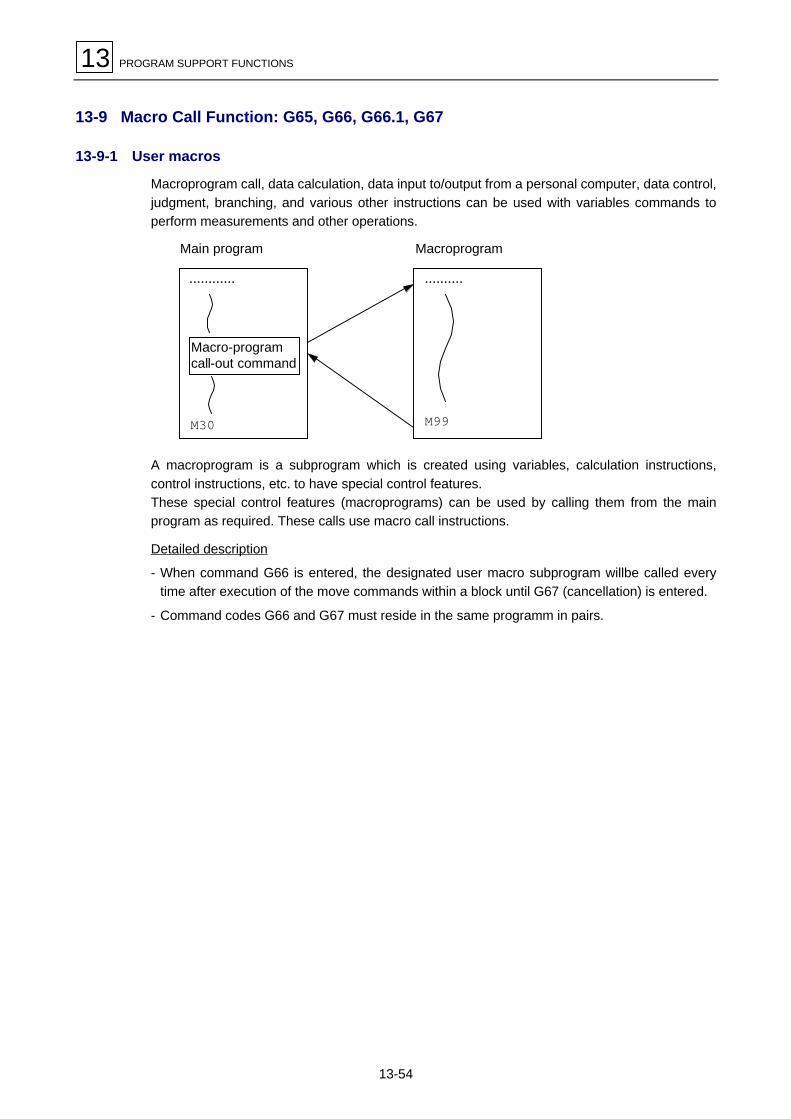
13 PROGRAM SUPPORT FUNCTIONS
13-54
13-9 Macro Call Function: G65, G66, G66.1, G67
13-9-1 User macros
Macroprogram call, data calculation, data input to/output from a personal computer, data control,judgment, branching, and various other instructions can be used with variables commands toperform measurements and other operations.
MacroprogramMain program
M30
Macro-programcall-out command
$$$$$$$$$$$$ $$$$$$$$$$
M99
A macroprogram is a subprogram which is created using variables, calculation instructions,control instructions, etc. to have special control features.These special control features (macroprograms) can be used by calling them from the mainprogram as required. These calls use macro call instructions.
Detailed description
- When command G66 is entered, the designated user macro subprogram willbe called everytime after execution of the move commands within a block until G67 (cancellation) is entered.
- Command codes G66 and G67 must reside in the same programm in pairs.

PROGRAM SUPPORT FUNCTIONS 13
13-55
13-9-2 Macro call instructions
Two types of macro call instructions are provided: single-call instructions used to call only at thedesignated block, and modal call instructions used to call at each block within a macro call mode.Modal call instructions are further divided into type A and type B.
1. Single call
Main program
G65P01Ll1 <argument>
Subprogram (O 01)
O01
M99
to subprogram
to main program
The designated user macro subprogram ends with M99.Instruction G65 calls the designated user macro subprogram only once.
Format:G65 P__ L__ <argument>
Repeat times
Program No. (When P is omitted, ownprogram will be repeated.)
<Argument>When argument is to be delivered to the user macro subprogram as a local variable, designatethe required data with the respective addresses. (Argument designation is not available for auser macro subprogram written in MAZATROL language.)In such a case, the argument can have a sign and a decimal point, irrespective of the address.Arguments can be specified using method I or II, as shown below.

13 PROGRAM SUPPORT FUNCTIONS
13-56
A. Argument specification I
Format: A_B_C_ $$$$$$$ X_Y_Z_
Detailed description
- An argument can be specified using all addresses, except G, L, N, O, and P.
- Except for I, J, and K, addresses does not need be specified in an alphabetical order.I_J_K_ ... CorrectJ_I_K_ ... Wrong
- Addresses whose specification is not required can be omitted.
- The relationship between addresses that can be specified using argument specification I, andvariables numbers in a user macro unit, is shown in the following table:
Relationship between address and variables number Call commands and usable addresses
Address specified usingmethod I
Variable in macro-program G65, G66 G66.1
A #1 " "
B #2 " "
C #3 " "
D #7 " "
E #8 " "
F #9 " "
G #10 × ×*
H #11 " "
I #4 " "
J #5 " "
K #6 " "
L #12 × ×*
M #13 " "
N #14 × ×*
O #15 × ×
P #16 × ×*
Q #17 " "
R #18 " "
S #19 " "
T #20 " "
U #21 " "
V #22 " "
W #23 " "
X #24 " "
Y #25 " "
Z #26 " "
": Usable ×: Unusable *: Usable in G66.1 modal

PROGRAM SUPPORT FUNCTIONS 13
13-57
B. Argument specification II
Format: A_B_C_I_J_K_I_J_K_$$$$$Detailed description- Up to a maximum of 10 sets of arguments that each consist of addresses I, J, and K, as well as
A, B, and C, can be specified.- If identical addresses overlap, specify them in the required order.- Addresses whose specification is not required can be omitted.- The relationship between addresses that can be specified using argument specification II, and
variables numbers in a user macro unit, is shown in the following table:
Argument specificationII addresses
Variables in macro-programs
Argument specificationII addresses
Variables in macro-programs
A #1 K5 #18
B #2 I6 #19
C #3 J6 #20
I1 #4 K6 #21
J1 #5 I7 #22
K1 #6 J7 #23
I2 #7 K7 #24
J2 #8 I8 #25
K2 #9 J8 #26
I3 #10 K8 #27
J3 #11 I9 #28
K3 #12 J9 #29
I4 #13 K9 #30
J4 #14 I10 #31
K4 #15 J10 #32
I5 #16 K10 #33
J5 #17
Note: In the table above, the numerals 1 through 10 have been added to addresses I, J, andJ just to denote the order of arrangement of the designated sets of arguments: thesenumerals are not included in actual instructions.
C. Combined use of argument specification I and II
When both method I and method II are used to specify arguments, only the latter of twoarguments which have an address corresponding to the same variable will become valid.
Example: Call command G65 A1.1 B–2.2 D3.3 I4.4 I7.7Variables#1: 1.1#2: –2.2#3:#4: 4.4#5:#6:#7: 7.7
If two arguments (D3.3 and I7.7) are designated for the variable of #7, only the latterargument (I7.7) will be used.

13 PROGRAM SUPPORT FUNCTIONS
13-58
2. Modal call, type A (Move command call)
Main program
G66P01Ll1 <argument>
Subprogram
O01
M99
to subprogram
to main program
G67to subprogram
For a block that has a move command code between G66 and G67, the designated user macrosubprogram is executed after that move command has been executed. The subprogram isexecuted an l1 number of times for the first call, or once for subsequent calls.For modal call of type A, the methods of specifying <argument> are the same as used for singlecall.
Format:G66 P__ L__ <argument>
Repeat times
Program No.
Detailed description
- When command G66 is entered, the designated user macro subprogram will be called everytime after execution of the move commands within a block until command G67 (cancellation) isentered.
- Command codes G66 and G67 must reside in the same program in pairs.Entry of a G67 command without a G66 command results in an alarm 857 INCORRECT USERMACRO G67 PROG.

PROGRAM SUPPORT FUNCTIONS 13
13-59
Example: Drilling cycle
N1G90G54G0X0Y0Z0N2G91G00X–50.Y–50.Z–200.N3G66P9010R–10.Z–30.F100N4X–50.Y–50.N5X–50.N6G67
M
Main program
Subprogram
MEP165
O9010N10G00Z#18M03N20G09G01Z#26F#9N30G00Z–[#18+#26]M99
To subprogram after execution of axis command
To main program
To subprogram after execution of axis command
To subprogram
W
N1
N4
N2X
Y
–50.
–100.
–50.–100.–150.
N5
N3
Argument F
Argument Z
Argument RN10
N30N20
Note 1: The designated subprogram is executed after the axis commands in the main programhave been executed.
Note 2: No subprograms are executed for the G67 block and its successors.
3. Modal call, type B (Block-to-block call)
The designated user macro subprogram is called unconditionally for each of the commandblocks present between G66.1 and G67. Execution of the macro program is repeated asspecified with L for the first call, and only once for each of subsequent calls.
Format:G66.1 P__ L__ <argument>
Repeat times
Program No.
Detailed description
- During the G66.1 mode, only the codes O, N, and G in each of the read command blocks areexecuted. No other codes in those blocks are executed; codes other than O, N, and G arehandled as arguments. However, only the last G-code and the N-codes following a code otherthan O or N become arguments.
- All significant blocks in the G66.1 mode are regarded as preceded by the command G65P_.
For example, the block of
N100G01G90X100. Y200. F400R1000in the G66.1P1000 mode is handled as equivalent to

13 PROGRAM SUPPORT FUNCTIONS
13-60
N100G65P1000G01G90X100. Y200. F400R1000.Note: Call is executed even for the G66.1 command block of the G66.1 mode, with the
relationship between the addresses of the arguments and the variables numbersbeing the same as for G65 (single call).
- The data range of the G, L, P, and N commands that you can set as new variables using theG66.1 mode is the same as the data range of usual NC commands.
- Sequence number N, modal G-codes, and O are all updated as modal information.
4. G-code macro call
The user macro subprograms of the required program number can be called just by setting G-codes.
Format:G×× <argument>
G-code which calls macro-subprogram
Detailed description
- The instruction shown above performs the same function as those of the instructions listedbelow. Which of these listed instructions will apply is determined by the parameter data to beset for each G-code.
M98P∆∆∆∆
G65P∆∆∆∆ <argument>
G66P∆∆∆∆ <argument>
G66.1P∆∆∆∆ <argument>
- Use parameters to set the relationship between G×× (macro call G-code) and P∆∆∆∆ (programnumber of the macro to be called).
- Of G00 through G255, up to a maximum of 10 command codes can be used with thisinstruction unless the uses of these codes are clearly predefined by EIA Standards, such asG00, G01, G02, etc.
- The command code cannot be included in user macro subprograms that have been calledusing G-codes.
5. Auxiliary command macro call (M-, S-, T-, or B-code macro call)
The user macro subprograms of the required program number can be called just by setting M-,S-, T-, or B-codes.
Format:Mm (or Ss, Tt and Bb)
M (or S, T and B) code which calls macro-subprogram
Detailed description (The following description also applies to S-, T-, and B-codes.)
- The instruction shown above performs the same function as those of the instructions listed

PROGRAM SUPPORT FUNCTIONS 13
13-61
below. Which of these listed instructions will apply is determined by the parameter data to beset for each M-code.
M98P∆∆∆∆
G65P∆∆∆∆Mm
G66P∆∆∆∆Mm
G66.1P∆∆∆∆Mm
- Use parameter to set the relationship between Mm (macro call M-code) and P∆∆∆∆ (programnumber of the macro to be called).Up to a maximum of 10 M-codes, ranging from M00 to M95, can be registered. Do not registerthe M-codes that are fundamentally required for your machine, nor M0, M1, M2, M30, and M96through M99.
- If registered auxiliary command codes are set in the user macro subprograms that have beencalled using M-codes, macro calls will not occur since those special auxiliary command codeswill be handled as usual ones (M-, S-, T-, or B-codes).
6. Differences in usage between commands M98, G65, etc.
- Arguments can be designated for G65, but cannot be designated for M98.
- Sequence numbers can be designated for M98, but cannot be designated for G65, G66, orG66.1.
- Command M98 executes a subprogram after M98 block commands other than M, P, H, and Lhave been executed, whereas G65 just branches the program into a subprogram without doinganything.
- Single-block stop will occur if the block of command M98 has addresses other than O, N, P, H,and L. For G65, however, single-block stop will not occur.
- The level of local variables is fixed for M98, but for G65 does change according to the depth ofnesting. (For example, #1s, if present before and after M98, always mean the same, but ifpresent before and after G65, they have different meanings.)
- Command M98 can have up to a maximum of 15 levels of call multiplexity when combined withG65, G66, or G66.1, whereas the maximum available number of levels for command G65 isfour when it is combined with G66 or G66.1.
7. Multiplexity of macro call commands
The maximum available number of levels of macro subprogram call is four, whether it is single ormodal. Arguments in macro call instructions become valid only within the level of the calledmacro. Since the multiplexity of macro call is of up to a maximum of four levels, arguments canbe included in a program as local variables each time a macro call is made.
Note 1: When a G65, G66, or G66.1 macro call or an auxiliary command macro call is made,nesting will be regarded as single-level and thus the level of local variables will alsoincrease by 1.
Note 2: For modal call of type A, the designated user macro subprogram is called each time amove command is executed. If, however, multiple G66s are present, the next usermacro subprogram will be called even for the move commands in the macro each timeaxis movement is done.
Note 3: User macro subprograms are cancelled in a reverse order to that in which they havebeen arranged.
Example:

13 PROGRAM SUPPORT FUNCTIONS
13-62
G66Pp1
G66Pp2
Zz2
Zz3
G67
Zz4
Zz5
Zz1
G67Macro p2
x1 w1 x2 M99
x1 w1 x2 M99
x1 w1 x2 M99
Macro p2 Macro p2
User macroprogram operation
Macro p1
Macro p1
Macro p1
(p2 call-out)
After z2 execution
(p1 call-out)
After z1 execution
Main program
(p1 call-out)
After z3 execution
(p1 cancel)
(p2 cancel)
8. User macro call based on interruption
Outline
Prior creation of special user macros for interrupt processing allows the user macros to beexecuted during automatic operation when a user macro interrupt signal is input. After the usermacro has been executed, the program can also be returned to the interrupted program blockand then started from this block.
Detailed description
- Format for selecting the user macro branching destination
MM96P_L_ M M MM97 (Branching mode off) M
(Branching mode on)When user macroprogram interruption signal is inputduring this space, the branch into the specified usermacroprogram will be applied.
- User macro interrupts can be processed even when the number of levels of macro callmultiplexity during the occurrence of an interrupt is four. The local variables' level of the usermacros used for interruption is the same as the level of the user macros existing during theoccurrence of an interrupt.

PROGRAM SUPPORT FUNCTIONS 13
13-63
Interruption return
O2000 MM96P5100G1X
MG65P2100
MM97 MM99
O2100
G1Y
M99
O5100
M99
Interruption branch
Interruption
(Level 4)
Interruption
(Level 3)
Local variable Local variable

13 PROGRAM SUPPORT FUNCTIONS
13-64
13-9-3 Variables
Of all types of variables available for the NC unit, only local variables, common variables, andpart of system variables are retained even after power-off.
1. Multiplexing of variables
Under user macro specifications, variables can have their identifiers (identification numbers)either transformed into variables, which is referred to as multiplexing, or replaced with<expression>.For <expression>, only one arithmetic expression (for either multiplication, division, addition, orsubtraction) can be used.
Example 1: Multiplexing variables#1=10 #10=20 #20=30 From #1 = 10, #[#[#1]] = #[#10] will result.#5=#[#[#1]] From #10 = 20, #[#10] = #20 will result. Therefore #5 = #20, i.e. #5
= 30 will result.
#1=10 #10=20 #20=30 From #1 = 10, #[#[#1]] = #[#10] will result.#5=1000 From #10 = 20, #[#10] = #20 will result. Therefore #20 = #5, i.e.#[#[#1]]=#5 #20 = 1000 will result.
Example 2: Replacing variables identifiers with <expression>#10=5#[#10+1]=1000 #6 = 1000 will result.#[#10–1]=–1000 #4 = –1000 will result.#[#10∗3]=100 #15 = 100 will result.#[#10/2]=100 #2 = –100 will result.
2. Undefined variables
Under user macro specifications, variables remaining unused after power-on or local variablesthat are not argument-specified by G65, G66, or G66.1 can be used as <empty>. Also, variablescan be forcibly made into <empty>.Variable #0 is always used as <empty> one, and this variable cannot be defined on the left sideof the expression.
A. Arithmetic expression
#1=#0.................#1 = <empty>
#2=#0+1 ............#2 = 1
#3=1+#0 ............#3 = 1
#4=#0∗10 ..........#4 = 0
#5=#0+#0 ..........#5 = 0
Note: Be careful that <empty> is handled the same as 0 during processing of expressions.
<empty> + <empty> = 0
<empty> + <constant> = constant
<constant> + <empty> = constant

PROGRAM SUPPORT FUNCTIONS 13
13-65
B. Applying variables
Application of an undefined variable alone causes even the address to be ignored.
If #1 = <empty>
G0X#1Y1000 is equivalent to G0Y1000, andG0X[#1+10]Y1000 is equivalent to G0X10Y1000.
C. Conditional expression
Only for EQ and NE, does <empty> differ from 0 in meaning.
If #101 = <empty> If #101 = 0
#101EQ#0 <empty> = <empty> holds. #101EQ#0 0 = <empty> does not hold.
#101NE0 <empty> ≠ 0 holds. #101NE0 0 ≠ 0 does not hold.
#101GE#0 <empty> ≥ <empty> holds. #101GE#0 0 ≥ <empty> holds.
#101GT0 <empty> > 0 does not hold. #101GT0 0 > 0 does not hold.
Hold-conditions and not-hold-conditions list(For conditional expressions including undefined variables)
EQ NE GT LT GE LERight side
Left side Empty Constant Empty Constant Empty Constant Empty Constant Empty Constant Empty Constant
Empty H H H H H
Constant H H H
H: Holds (The conditional expression holds.)Blank: The conditional expression does not hold.

13 PROGRAM SUPPORT FUNCTIONS
13-66
13-9-4 Types of variables
1. Common variables (#100 to #199, and #500 to #999)
Common variables refer to the variables to be used in common at any position. The identifiers ofcommon variables which can be used are from #100 to #199, or from #500 to #999.
2. Local variables (#1 to #33)
Local variables refer to variables that can be defined as <argument> when calling a macrosubprogram, or those which can be used locally within the main program or a subprogram. Thereis no relationship between macros. Thus, these variables can be overlapped on each other, butup to a maximum of four levels of overlapping.
G65Pp1Ll1 <argument>
where p1 : Program number
l1 : Number of repeat times
<Argument> must be: Aa1 Bb1 Cc1 $$$ Zz1.
The following represents the relationship between the address specified by <argument> and thelocal variables number used in the user macro unit:
Call commands Call commands
G65G66
G66.1Argumentaddress
Localvariable G65
G66G66.1
Argumentaddress
Localvariable
" " A #1 " " R #18
" " B #2 " " S #19
" " C #3 " " T #20
" " D #7 " " U #21
" " E #8 " " V #22
" " F #9 " " W #23
× ×* G #10 " " X #24
" " H #11 " " Y #25
" " I #4 " " Z #26
" " J #5 – #27
" " K #6 – #28
× ×* L #12 – #29
" " M #13 – #30
× ×* N #14 – #31
× × O #15 – #32
× ×* P #16 – #33
" " Q #17
Argument addresses marked as × in the table above cannot be used. Only during the G66.1mode, however, can argument addresses marked with an asterisk (*) in this table be additionallyused. Also, the dash sign (–) indicates that no address is crosskeyed to the local variablesnumber.

PROGRAM SUPPORT FUNCTIONS 13
13-67
1. Local variables for a subprogram can be defined by specifying <argument> when calling amacro.
G65P9900A60.S100.F800
M02
#5=#4010G91G01 X[#19∗COS[#1]]
Y[#19∗SIN[#1]]F#9M99
A (#1)=60.000
F (#9)=800
S (#19)=100.000
Main program Subprogram (O9900)
To subprogram
Control of move andothers after referringto local variables.
Local variable setting by argument
Local variabledata table
2. Within a subprogram, local variables can be freely used.
G65P1A100.B50.J10.F500
#30=FUP[#2/#5/2]#5=#2/#30/2M98H100L#30X#1M99N100G1X#1F#9Y#5X–#1X#5M99
A (#1) 100.000B (#2) 50.000F (#9) 500J (#5) 10.000 → 8.333
(#30) → 3.
Main program Subprogram (O1)
Local variable set by argumentLocal variablescan be changed inthe sub-program
Example of face milling
To subprogram
Local variabledata table
B
J
A
In the sample program for face-milling that is shown above, although the argument J has initiallybeen programmed as a machining pitch of 10 mm, it has been changed into 8.333 mm to ensureequal-pitched machining.Also, local variable #30 contains the calculated data about the number of times of reciprocalmachining.

13 PROGRAM SUPPORT FUNCTIONS
13-68
3. Local variables can be used for each of the four levels of macro call separately. For themain program (macro level 0), separate local variables are also provided. The localvariables of level 0, however, cannot be designated with arguments.
M99
#1=0.1#2=0.2#3=0.3
P65P1A1.B2.C3.
M02
Local variable (0)#1 0.100#2 0.200#3 0.300
#33
G65P100A100.B200.
M99
G65P10A10.B20.C30.
M99
Local variable (1)A(#1) 1.000B(#2) 2.000C(#3) 3.000D(#7)
Z(#26)
#33
Local variable (2)A(#1) 10.000B(#2) 20.000C(#3) 30.000D(#7)
Z(#26)
#33
Local variable (3)A(#1) 100.000B(#2) 200.000C(#3)
Z(#26)
#33
Main (Level 0) O1 (Macro level 1) O10 (Macro level 2) O100 (Macro level 3)
How the local variables are currently being used is displayed on the screen.For further details, refer to the Operating Manual.

PROGRAM SUPPORT FUNCTIONS 13
13-69
3. Macro interface input system variables (#1000 to #1035)
You can check the status of an interface input signal by reading the value of the appropriatevariables number (#1000 to #1035).The read value of the variables number is either 1 (contact closed) or 0 (contact open). You canalso check the status of all input signals of the variables from #1000 to #1031 by reading thevalue of variables number 1032. Variables from #1000 to #1035 can only be read; they cannot beplaced on the left side of an arithmetic expression.
System variable Points Interface input signal System variable Points Interface input signal
#1000 1 Register R72, bit 0 #1016 1 Register R73, bit 0
#1001 1 Register R72, bit 1 #1017 1 Register R73, bit 1
#1002 1 Register R72, bit 2 #1018 1 Register R73, bit 2
#1003 1 Register R72, bit 3 #1019 1 Register R73, bit 3
#1004 1 Register R72, bit 4 #1020 1 Register R73, bit 4
#1005 1 Register R72, bit 5 #1021 1 Register R73, bit 5
#1006 1 Register R72, bit 6 #1022 1 Register R73, bit 6
#1007 1 Register R72, bit 7 #1023 1 Register R73, bit 7
#1008 1 Register R72, bit 8 #1024 1 Register R73, bit 8
#1009 1 Register R72, bit 9 #1025 1 Register R73, bit 9
#1010 1 Register R72, bit 10 #1026 1 Register R73, bit 10
#1011 1 Register R72, bit 11 #1027 1 Register R73, bit 11
#1012 1 Register R72, bit 12 #1028 1 Register R73, bit 12
#1013 1 Register R72, bit 13 #1029 1 Register R73, bit 13
#1014 1 Register R72, bit 14 #1030 1 Register R73, bit 14
#1015 1 Register R72, bit 15 #1031 1 Register R73, bit 15
System variable Points Interface input signal
#1032 32 Register R72 and R73
#1033 32 Register R74 and R75
#1034 32 Register R76 and R77
#1035 32 Register R78 and R79
Note: The following interface input signals are used exclusively in the NC system operation(cannot be used for other purposes).
Interface input signal Description
Register R72, bit 0 Touch sensor mounted in the spindle
Register R72, bit 4 X- and Y-axis machine lock ON
Register R72, bit 5 M-, S-, T-code lock ON
Register R72, bit 6 Z-axis machine lock ON

13 PROGRAM SUPPORT FUNCTIONS
13-70
4. Macro interface output system variables (#1100 to #1135)
You can send an interface output signal by assigning a value to the appropriate variablesnumber (#1100 to #1135).All output signals can take either 0 or 1.You can also send all output signals of the variables from #1100 to #1131 at the same time byassigning a value to variables number 1132. In addition to the data writing for offsetting the#1100 to #1135 output signals, the reading of the output signal status can be done.
System variable Points Interface output signal System variable Points Interface output signal
#1100 1 Register R172, bit 0 #1116 1 Register R173, bit 0
#1101 1 Register R172, bit 1 #1117 1 Register R173, bit 1
#1102 1 Register R172, bit 2 #1118 1 Register R173, bit 2
#1103 1 Register R172, bit 3 #1119 1 Register R173, bit 3
#1104 1 Register R172, bit 4 #1120 1 Register R173, bit 4
#1105 1 Register R172, bit 5 #1121 1 Register R173, bit 5
#1106 1 Register R172, bit 6 #1122 1 Register R173, bit 6
#1107 1 Register R172, bit 7 #1123 1 Register R173, bit 7
#1108 1 Register R172, bit 8 #1124 1 Register R173, bit 8
#1109 1 Register R172, bit 9 #1125 1 Register R173, bit 9
#1110 1 Register R172, bit 10 #1126 1 Register R173, bit 10
#1111 1 Register R172, bit 11 #1127 1 Register R173, bit 11
#1112 1 Register R172, bit 12 #1128 1 Register R173, bit 12
#1113 1 Register R172, bit 13 #1129 1 Register R173, bit 13
#1114 1 Register R172, bit 14 #1130 1 Register R173, bit 14
#1115 1 Register R172, bit 15 #1131 1 Register R173, bit 15
System variable Points Interface output signal
#1132 32 Register R172 and R173
#1133 32 Register R174 and R175
#1134 32 Register R176 and R177
#1135 32 Register R178 and R179
Note 1: Data of the system variables from #1100 to #1135 is saved according to the logicallevel (1 or 0) of the signal that has been lastly sent. The saved data is cleared bypower-on/off automatically.
Note 2: The following applies if a data other than 1 or 0 is assigned to the variables from #1100to #1131:
<empty> is regarded as equal to 0.
Data other than 0 and <empty> is regarded as equal to 1.
Data less than 0.00000001, however, is regarded as undefined.

PROGRAM SUPPORT FUNCTIONS 13
13-71
32 bit
#1033
#1034
#1035
#1100
#1101
#1102
#1003
#1128
#1129
#1130
#1131
Macro-instruction
Input signal Output signal
Read onlyRead andwrite
#1133
#1134
#1135
(R72, R73) #1032 #1132 (R172, R173)
(R76, R77)
(R74, R75)
(R78, R79)
32bit
(R176, R177)
(R174, R175)
(R178, R179)
#1000
#1001
#1002
#1003
#1028
#1029
#1030
#1031
5. Tool offset
Standard 128 setsOptional 512 sets
Range of variable Nos. Type A Type B
#10001 - #10000+n #2001 - #2000+n ○ ○ Length Geom. offset
#11001 - #11000+n #2201 - #2200+n × ○ Length Wear compensation
#16001 - #16000+n*(#12001 - #12000+n)
#2401 - #2400+n × ○ Dia. Geom. offset
#17001 - #17000+n*(#13001 - #13000+n)
#2601 - #2600+n × ○ Dia. Wear compensation
*: The numbers of variables used for tool offset depend upon a parameter:
F96 bit 0 = 0: #16001 to #16000+n, and #17001 to #17000+n= 1: #12001 to #12000+n, and #13001 to #13000+n.
Using variables numbers, you can read tool data or assign data.Usable variables numbers are of the order of either #10000 or #2000. For the order of #2000,however, only up to 200 sets of tool offsets can be used.

13 PROGRAM SUPPORT FUNCTIONS
13-72
The last three digits of a variables number denote a tool offset number.As with other variables, tool offset data is to contain the decimal point. The decimal point musttherefore be included if you want to set data that has decimal digits.
#101=1000#10001=#101#102=#10001 H1=1000.000
#101=1000.0
#102=1000.0
Afterexecution
Program example Common variables Tool offset data
Example: Tool offset data measuring
G28Z0T01M06#1=#5003G00Z–500.G31Z–100.F100#10001=#5063–#1 M
#1
H1
Return to zero pointTool change (Spindle T01)Starting point memoryRapid feed to safe positionSkip measuringMeasuring distance calculationand tool offset data setting #5063
Sensor
G00
G31
Note: The example shown above does not allow for any skip sensor signal delay. Also,#5003 denotes the position of the starting point of the Z-axis, and #5063 denotes theskip coordinate of the Z-axis, that is, the position at which a skip signal was input duringexecution of G31.
6. Workpiece coordinate system offset
Using variables numbers from 5201 to 5336, you can read workpiece coordinate system offsetdata or assign data.
Note: The number of controllable axes depends on the machine specifications.
Axis No.Data name
1st axis 2nd axis 3rd axis16thaxis
Remarks
SHIFT #5201 #5202 #5203 #5216 An external data input/output optionalspec. is required.
G54 #5221 #5222 #5223 #5236
G55 #5241 #5242 #5243 #5256
G56 #5261 #5262 #5263 #5276
G57 #5281 #5282 #5283 #5296
G58 #5301 #5302 #5303 #5316
G59 #5321 #5322 #5323 #5336
A workpiece coordinate system offsetfeature is required.
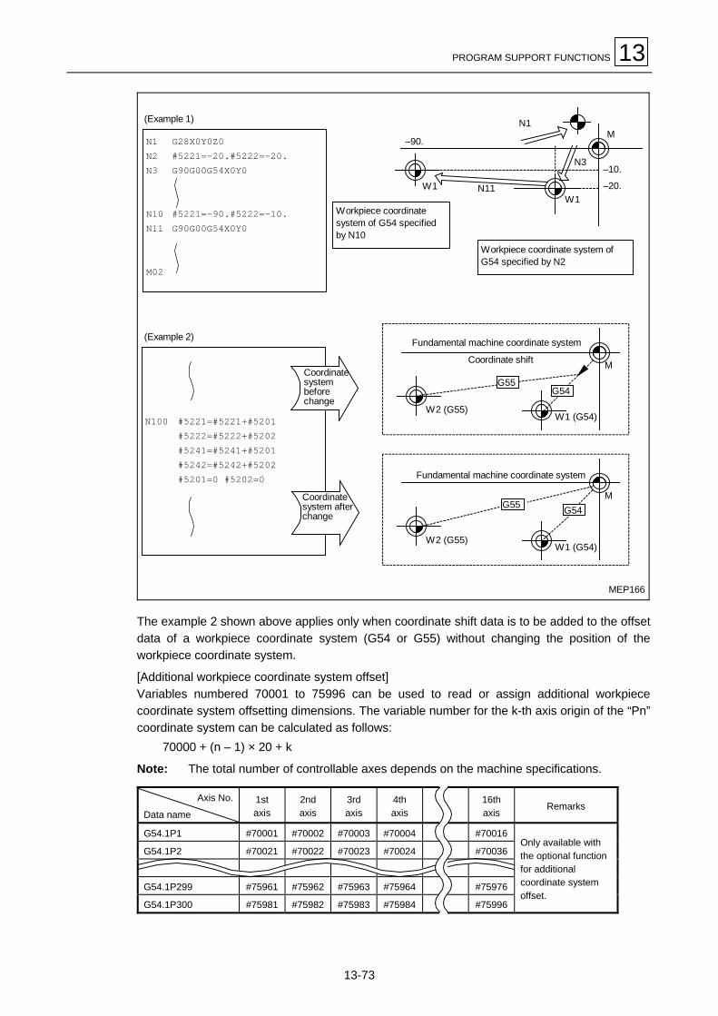
PROGRAM SUPPORT FUNCTIONS 13
13-73
MEP166
N100 #5221=#5221+#5201#5222=#5222+#5202#5241=#5241+#5201#5242=#5242+#5202#5201=0 #5202=0
Coordinatesystembeforechange
Coordinatesystem afterchange
N1 G28X0Y0Z0N2 #5221=–20.#5222=–20.N3 G90G00G54X0Y0
N10 #5221=–90.#5222=–10.N11 G90G00G54X0Y0
M02
W1
N1
N11W1
–20.
–10.N3
–90.M
Workpiece coordinatesystem of G54 specifiedby N10
(Example 1)
(Example 2)
Workpiece coordinate system ofG54 specified by N2
Fundamental machine coordinate system
Coordinate shift
Fundamental machine coordinate system
W2 (G55)W1 (G54)
M
G55
W2 (G55)W1 (G54)
MG54G55
G54
The example 2 shown above applies only when coordinate shift data is to be added to the offsetdata of a workpiece coordinate system (G54 or G55) without changing the position of theworkpiece coordinate system.
[Additional workpiece coordinate system offset]Variables numbered 70001 to 75996 can be used to read or assign additional workpiececoordinate system offsetting dimensions. The variable number for the k-th axis origin of the “Pn”coordinate system can be calculated as follows:
70000 + (n – 1) × 20 + k
Note: The total number of controllable axes depends on the machine specifications.
Axis No.
Data name1staxis
2ndaxis
3rdaxis
4thaxis
16thaxis
Remarks
G54.1P1 #70001 #70002 #70003 #70004 #70016
G54.1P2 #70021 #70022 #70023 #70024 #70036
G54.1P299 #75961 #75962 #75963 #75964 #75976
G54.1P300 #75981 #75982 #75983 #75984 #75996
Only available withthe optional functionfor additionalcoordinate systemoffset.

13 PROGRAM SUPPORT FUNCTIONS
13-74
Alternatively, variables numbered 7001 to 7956 can be used to read or assign additional work-piece coordinate system offsetting dimensions. The variable number for the k-th axis origin of the“Pn” coordinate system can be calculated as follows:
7000 + (n – 1) × 20 + k
Note: The total number of controllable axes depends on the machine specifications.
Axis No.
Data name1staxis
2ndaxis
3rdaxis
4thaxis
16thaxis
Remarks
G54.1P1 #7001 #7002 #7003 #7004 #7016
G54.1P2 #7021 #7022 #7023 #7024 #7036
G54.1P3 #7041 #7042 #7043 #7044 #7056
G54.1P48 #7941 #7942 #7943 #7944 #7956
Only available withthe optional functionfor additional coordi-nate system offset.
7. NC alarm (#3000)
The NC unit can be forced into an alarm status using variables number 3000.
#3000 = 70 (CALL#PROGRAMMER#TEL#530)
Alarm No. Alarm message
The setting range for the alarm No. is from 1 to 6999.The maximum available length of the alarm message is 31 characters.
Note: The type of alarm message displayed on the screen depends on the designated alarmnumber, as indicated in the following table.
Designated alarm No. Displayed alarm No. Displayed alarm message
1 to 20 [Designated alarm No.] + 979 Message preset for the displayed alarm No. *1
21 to 6999 [Designated alarm No.] + 3000 Designated alarm message as it is *2
*1 Refers to alarm Nos. 980 to 999 whose messages are preset as indicated in Alarm List.
*2 Display of a message as it is set in the macro statement.
Operation stopby NC alarm
Program ex. 1 (Command for displayof “980 MACRO USER ALARM 1” oncondition of #1=0)
Program ex. 2 (Command for display of“3021#ORIGINAL#ALARM#1” on conditionof #2=0)
Operation stop byNC alarm
M
IF[#1NE0]GOTO100#3000=1N100$$$$$$$$$$$$
M
M
IF[#2NE0]GOTO200#3000=21(#ORIGINAL#ALARM#1)N200$$$$$$$$$$
M
980 MACRO USER ALARM 1
3021#ORIGINAL#ALARM#1

PROGRAM SUPPORT FUNCTIONS 13
13-75
8. Integrated time (#3001, #3002)
Using variables #3001 and #3002, you can read the integrated time existing during automaticoperation or assign data.
Type Variable No. Unit Data at power-on Initialization Counting
Integrated time 1 Always during power-on
Integrated time 2
3001
3002msec
Same as atpower-off
Data is assignedin variables. During auto-starting
The integrated time is cleared to 0 after having reached about 2.44 × 10¹¹ msec (about 7.7years).
#3001=0WHILE[#3001LE#20]DO1
END1M99
G65P9010T (Allowable time msec)
O9010
To subprogram
Into local variable #20
Execution of blocks from DO1 to END1is repeated until the allowable time haselapsed, and then the control jumps tothe end block of M99.
Local variable
T#20______
9. Validation/invalidation of single-block stop or auxiliary-function finish signal wait (#3003)
Assigning one of the values listed in the table below to variables number 3003 allows single-block stop to be made invalid at subsequent blocks or the program to be advanced to the nextblock without ever having to wait for the arrival of an auxiliary-function code (M, S, T, or B)execution finish signal (FIN).
#3003 Single block stop Auxiliary-function completion signal
0 Effective Wait
1 Ineffective Wait
2 Effective No wait
3 Ineffective No wait
Note: Variable #3003 is cleared to 0 by resetting.

13 PROGRAM SUPPORT FUNCTIONS
13-76
10. Validation/invalidation of feed hold, feed rate override, or G09 (#3004)
Feed hold, feed rate override, or G09 can be made valid or invalid for subsequent blocks byassigning one of the values listed in the table below to variables number 3004.
Bit 0 Bit 1 Bit 2#3004Contents (Value) Feed hold Feed rate override G09 check
0 Effective Effective Effective
1 Ineffective Effective Effective
2 Effective Ineffective Effective
3 Ineffective Ineffective Effective
4 Effective Effective Ineffective
5 Ineffective Effective Ineffective
6 Effective Ineffective Ineffective
7 Ineffective Ineffective Ineffective
Note 1: Variable #3004 is cleared to 0 by resetting.
Note 2: Each of the listed bits makes the function valid if 0, or invalid if 1.
11. Program stop (#3006)
Use of variables number 3006 allows the program to be stopped after execution of theimmediately preceding block.
Format:#3006 = 1 (CHECK OPERAT)
Character string to be displayed
Additional setting of a character string (in 29 characters at maximum) in parentheses allows therequired stop message to be displayed on the monitor.
12. Mirror image (#3007)
The mirror image status of each axis at one particular time can be checked by reading variablesnumber 3007.Variable #3007 has its each bit crosskeyed to an axis, and these bits indicate that:If 0, the mirror image is invalid.If 1, the mirror image is valid.
Bit 15 14 13 12 11 10 9 8 7 6 5 4 3 2 1 0
Axis no. 6 5 4 3 2 1
13. G-command modal status
The G-command modal status in a pre-read block can be checked using variables numbers from4001 to 4027. For variables numbers from #4201 to #4227, the modal status of the block beingexecuted can be checked in a similar manner to that described above.
Variable Nos.Block
pre-readBlock
executedFunction
#4001 #4201 Interpolation mode G0-G3 : 0-3, G2.1 : 2.1, G3.1 : 3.1
#4002 #4202 Plane selection G17 : 17, G18 : 18, G19 : 19 #4003 #4203 Absolute/Incremental programming G90/91 : 90/91
#4004 #4204 Pre-move stroke check G22 : 22, G23 : 23

PROGRAM SUPPORT FUNCTIONS 13
13-77
Variable Nos.Block
pre-readBlock
executedFunction
#4005 #4205 Feed specification G94 : 94, G95 : 95
#4006 #4206 Inch/metric selection G20/21 : 20/21
#4007 #4207 Tool diameter offset G40 : 40, G41 : 41, G42 : 42 #4008 #4208 Tool length offset G43/44 : 43/44, G43.4 : 43.4, G43.5 : 43.5, G49 : 49 #4009 #4209 Fixed cycle G80 : 80, G273/274 : 273/274, G276 : 276, G81-G89 : 81-89
#4010 #4210 Returning level G98 : 98, G99 : 99
#4011 #4211 Scaling OFF/ON G50/51 : 50/51
#4012 #4212 Workpiece coordinate system G54-G59 : 54-59, G54.1 : 54.1
#4013 #4213 Mode of machining (feed) G61-64 : 61-64, G61.1 : 61.1, G61.4 : 61.4
#4014 #4214 Macro modal call G66 : 66, G66.1 : 66.1, G67 : 67
#4015 #4215 Shaping function G40.1 : 40.1, G41.1 : 41.1, G42.1 : 42.1 #4016 #4216 Programmed coordinate conversion ON/OFF G68/69 : 68/69
#4017 #4217
#4018 #4218
#4019 #4219 Mirror image by G-codes (5-surf. machining) G17.1-17.9 : 17.1-17.9, G45.1 : 45.1 G49.1 : 49.1, G50.1 : 50.1, G51.1 : 51.1
#4020 #4220 Cross machining control G110 : 110, G110.1 : 110.1, G111 : 111 #4021 #4221 #4022 #4222
#4023 #4223 Polygonal machining and Hobbing G50.2 : 50.2, G51.2 : 51.2, G113 : 113, G114.3 : 114.3
#4024 #4224
#4025 #4225
#4026 #4226
#4027 #4227 Dynamic offsetting II G54.2 : 54.2
14. Other modal information
Modal information about factors other than the G-command modal status in a pre-read block canbe checked using variables numbers from 4101 to 4132. For variables numbers from #4301 to#4330, the modal information of the block being executed can be checked in a similar manner tothat described above.
Variable Nos. Variable Nos.Block
pre-readBlock
executedModal information Block
pre-readBlock
executedModal information
#4101 #4301 #4113 #4313 Miscellaneous function$$$M#4102 #4302 No. 2 miscellaneous function #4114 #4314 Sequence No.$$$N#4103 #4303 #4115 #4315 Program No.$$$O#4104 #4304 #4116 #4316#4105 #4305 #4117 #4317#4106 #4306 #4118 #4318
#4107 #4307 Tool diameter offset No.$$$D #4119 #4319 Spindle function$$$S
#4108 #4308 #4120 #4320 Tool function$$$T
#4109 #4309 Rate of feed$$$F #4130 #4330 Addt. workpiece coordinate systemG54-G59: 0, G54.1P1-P300: 1-300
#4110 #4310
#4111 #4311 Tool length offset No.$$$H#4131 Surface type
Upper: 0, 0°/180°: 1, 90°/270°: 2
#4112 #4312 #4132Machining surfaceUpper: 5, 0°: 6, 90°: 7, 180°: 8,270°: 9

13 PROGRAM SUPPORT FUNCTIONS
13-78
15. Position information
Using variables numbers from #5001 to #5116, you can check the ending-point coordinates ofthe previous block, machine coordinates, workpiece coordinates, skip coordinates, tool positionoffset coordinates, and servo deviations.
Position information
Axis No.
End pointcoordinatesof previous
block
Machinecoordinate
Workpiececoordinate
Skipcoordinate
Toolpositionoffset
coordinates
Servodeviationamount
1 #5001 #5021 #5041 #5061 #5081 #5101
2 #5002 #5022 #5042 #5062 #5082 #5102
3 #5003 #5023 #5043 #5063 #5083 #5103
16 #5016 #5036 #5056 #5076 #5096 #5116
Remarks(Reading during move)
Possible Impossible Impossible Possible Impossible Possible
Note: The number of controllable axes depends on the machine specifications.
1. The ending-point coordinates and skip coordinates read will be those related to theworkpiece coordinate system.
2. Ending-point coordinates, skip coordinates, and servo deviations can be checked evenduring movement. Machine coordinates, workpiece coordinates, and tool position offsetcoordinates must be checked only after movement has stopped.
MEP167
Readcommand
W
W
G01
M
G00
MFundamental machine coordinate system
Workpiece coordinate system
End pointcoordinates
Workpiececoordinates
Machinecoordinates
Machinecoordinate system
Workpiececoordinate system

PROGRAM SUPPORT FUNCTIONS 13
13-79
3. Skip coordinates denote the position at which a skip signal has turned on at the block ofG31. If the skip signal has not turned on, skip coordinates will denote the correspondingending-point position.
Readcommand
Skip coordinate value
Gauge, etc.
MEP168
4. The ending-point position denotes the tool tip position which does not allow for any tooloffsets, whereas machine coordinates, workpiece coordinates, and skip coordinates denotethe tool reference-point position which allows for tool offsets.
Mark !: Read after confirmation of stop.Mark ": Can be read during move.
Skip signal
F (Speed)
Skip signal inputcoordinates
W
M
Workpiececoordinates
Machine coordinates
Workpiececoordinate system
Machinecoordinate system
MEP169
The input coordinates of a skip signal denote the position within the workpiece coordinatesystem. The coordinates stored in variables from #5061 to #5066 are those existing whenskip signals were input during movement of the machine. These coordinates can thereforebe read at any time after that. See Chapter 15 for further details.
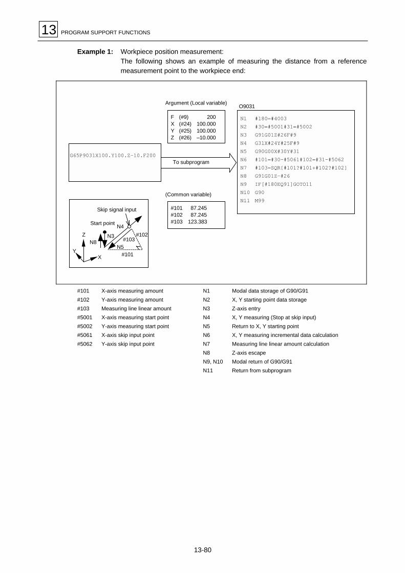
13 PROGRAM SUPPORT FUNCTIONS
13-80
Example 1: Workpiece position measurement:The following shows an example of measuring the distance from a referencemeasurement point to the workpiece end:
O9031
N1 #180=#4003N2 #30=#5001#31=#5002N3 G91G01Z#26F#9N4 G31X#24Y#25F#9N5 G90G00X#30Y#31N6 #101=#30–#5061#102=#31–#5062N7 #103=SQR[#101?#101+#102?#102]N8 G91G01Z–#26N9 IF[#180EQ91]GOTO11N10 G90N11 M99
G65P9031X100.Y100.Z-10.F200
F (#9) 200X (#24) 100.000Y (#25) 100.000Z (#26) –10.000
#101 87.245#102 87.245#103 123.383
(Common variable)
Argument (Local variable)
Skip signal input
Start point N4
N3N8
#102#103
N5
Z
YX #101
To subprogram
#101 X-axis measuring amount N1 Modal data storage of G90/G91#102 Y-axis measuring amount N2 X, Y starting point data storage#103 Measuring line linear amount N3 Z-axis entry#5001 X-axis measuring start point N4 X, Y measuring (Stop at skip input)#5002 Y-axis measuring start point N5 Return to X, Y starting point#5061 X-axis skip input point N6 X, Y measuring incremental data calculation#5062 Y-axis skip input point N7 Measuring line linear amount calculation
N8 Z-axis escapeN9, N10 Modal return of G90/G91N11 Return from subprogram
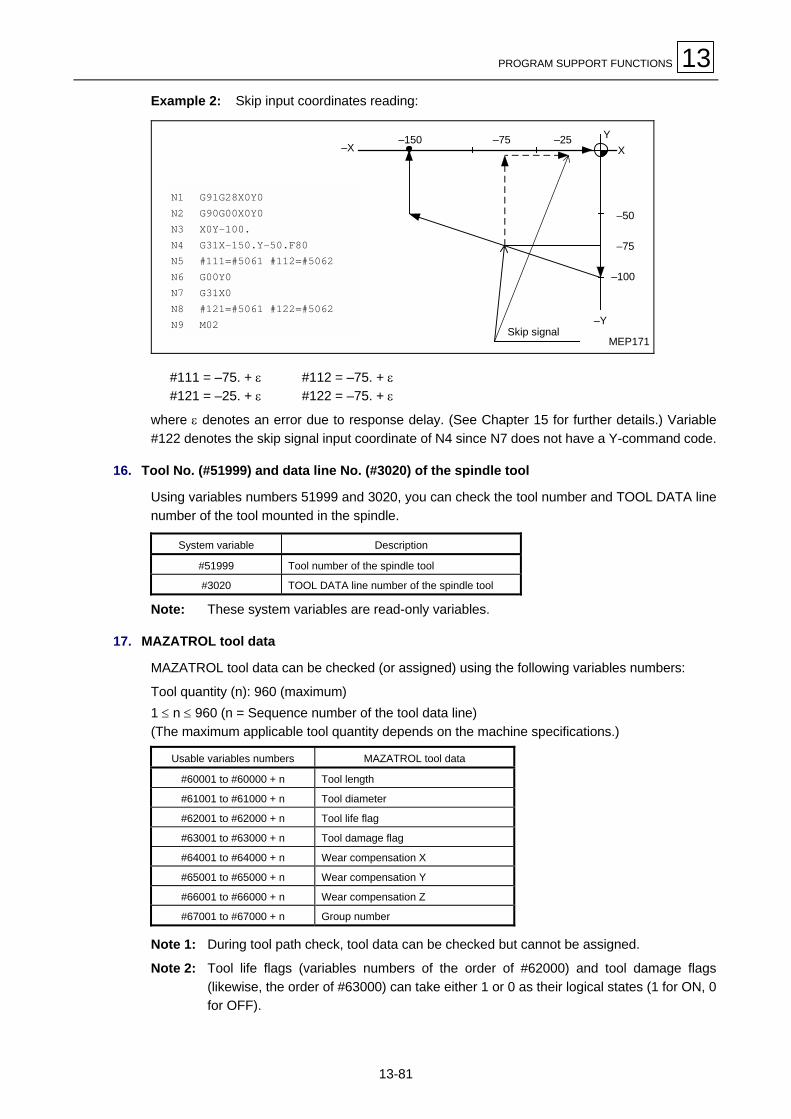
PROGRAM SUPPORT FUNCTIONS 13
13-81
Example 2: Skip input coordinates reading:
XY
–50
–75
–100
–Y
–25–75–150–X
N1 G91G28X0Y0N2 G90G00X0Y0N3 X0Y–100.N4 G31X–150.Y–50.F80N5 #111=#5061 #112=#5062N6 G00Y0N7 G31X0N8 #121=#5061 #122=#5062N9 M02
Skip signalMEP171
#111 = –75. + ε #112 = –75. + ε#121 = –25. + ε #122 = –75. + ε
where ε denotes an error due to response delay. (See Chapter 15 for further details.) Variable#122 denotes the skip signal input coordinate of N4 since N7 does not have a Y-command code.
16. Tool No. (#51999) and data line No. (#3020) of the spindle tool
Using variables numbers 51999 and 3020, you can check the tool number and TOOL DATA linenumber of the tool mounted in the spindle.
System variable Description
#51999 Tool number of the spindle tool
#3020 TOOL DATA line number of the spindle tool
Note: These system variables are read-only variables.
17. MAZATROL tool data
MAZATROL tool data can be checked (or assigned) using the following variables numbers:
Tool quantity (n): 960 (maximum)1 ≤ n ≤ 960 (n = Sequence number of the tool data line)(The maximum applicable tool quantity depends on the machine specifications.)
Usable variables numbers MAZATROL tool data
#60001 to #60000 + n Tool length
#61001 to #61000 + n Tool diameter
#62001 to #62000 + n Tool life flag
#63001 to #63000 + n Tool damage flag
#64001 to #64000 + n Wear compensation X
#65001 to #65000 + n Wear compensation Y
#66001 to #66000 + n Wear compensation Z
#67001 to #67000 + n Group number
Note 1: During tool path check, tool data can be checked but cannot be assigned.
Note 2: Tool life flags (variables numbers of the order of #62000) and tool damage flags(likewise, the order of #63000) can take either 1 or 0 as their logical states (1 for ON, 0for OFF).

13 PROGRAM SUPPORT FUNCTIONS
13-82
18. EIA/ISO tool data
Using variables numbers tabulated below, EIA/ISO tool data (tool life management data) can beread or updated, as required.
Tool quantity (n): 960 (maximum)1 ≤ n ≤ 960 (n = Sequence number of the tool data line)
System variables Corresponding data
#40001 to #40000 + n Tool length offset numbers or tool length offset amounts
#41001 to #41000 + n Tool diameter offset numbers or tool diameter offset amounts
#42001 to #42000 + n Tool life flags
#43001 to #43000 + n Tool damage flags
#44001 to #44000 + n Tool data flags
#45001 to #45000 + n Tool operation time (sec)
#46001 to #46000 + n Tool life time (sec)
Note 1: During tool path check, tool data can be checked but cannot be assigned.
Note 2: Tool life flags (variables numbers of the order of #42000) and tool damage flags(likewise, the order of #43000) can take either 1 or 0 as their logical states (1 for ON, 0for OFF).
Note 3: The identification between number and amount of tool length or diameter offset ismade by referring to the tool data flag.
Tool data flag bit 0 bit 1 bit 2 bit 3
Length offset No. 0 0 – –
Length offset amount 0 1 – –
Diam. offset No. – – 0 0
Diam. offset amount – – 0 1
19. Date and time (Year-month-day and hour-minute-second)
Variables numbered 3011 and 3012 can be used to read date and time data.
Variable Nos. Description
#3011 Date (Year-month-day)
#3012 Time (Hour-minute-second)
Example: If the date is December 15, 1995 and the time is 16:45:10, data is set as follows inthe corresponding system variables:
#3011 = 951215#3012 = 164510.
20. Total number of machined parts and the number of parts required
Variables numbered 3901 and 3902 can be used to read or assign the total number of machinedparts and the number of parts required.
Variable Nos. Description
#3901 Total number of machined parts
#3902 Number of parts required
Note 1: These variables must be integers from 0 to 9999.
Note 2: Data reading and writing by these variables is surely suppressed during tool pathchecking.

PROGRAM SUPPORT FUNCTIONS 13
13-83
21. Setting and using variables names
Any variables name can be assigned to each of common variables #500 through #519. Thevariables name, however, must be of seven alphanumerics or less that begin with a letter of thealphabet.
Format:SETVNn [NAME1, NAME2, .....]
Starting number of the variable to be named
Name of #n (Variables name)
Name of #n + 1 (Varaibles name)
Each variables name must be separated using the comma (,).
Detailed description
- Once a variables name has been set, it remains valid even after power-off.
- Variables in a program can be called using the variables names. The variable to be called must,however, be enclosed in brackets ([ ]).Example: G01X[#POINT1]
[#TIMES]=25- Variables names can be checked on the USER PARAMETER No. 1 display. The names
assigned to variables #500 to #519 are displayed at F47 to F66.Example: Program SETVN500[ABC,EFG]
On the displayF46 0F47 ABC ← Variables name assigned to #500F48 EFG ← Variables name assigned to #501F49 ← Variables name assigned to #502F50

13 PROGRAM SUPPORT FUNCTIONS
13-84
13-9-5 Arithmetic operation commands
Various operations can be carried out between variables using the following format.
#i = <expression>
where <expression> must consist of a constant(s), a variable(s), a function(s), or an operator(s).In the table given below, constants can be used instead of #j and/or #k.
[1] Definition/replacement ofvariables
#i=#j Definition/replacement
[2] Additional-type operations #i=#j+#k Addition#i=#j–#k Subtraction#i=#jOR#k Logical additon (For each of 32 bits)#i=#jXOR#k Exclusive OR (For each of 32 bits)
[3] Multiplicative-typeoperations
#i=#j∗#k Multiplication#i=#j/#k Division#i=#jMOD#k Surplus#i=#jAND#k Logical product (For each of 32 bits)
[4] Functions #i=SIN[#k] Sine#i=COS[#k] Cosine#i=TAN[#k] Tangent (tanq is used as sinq/cosq.)#i=ATAN[#j] Arc-tangent (Either ATAN or ATN can be used.)#i=ACOS[#j] Arc-cosine#i=SQRT[#k] Square root (Either SQRT or SQR is available.)#i=ABS[#k] Absolute value#i=BIN[#k] BINARY conversion from BCD#i=BCD[#k] BCD conversion from BINARY#i=ROUND[#k] Rounding to the nearest whole number (Either ROUND or
RND is available.)#i=FIX[#k] Cutting away any decimal digits#i=FUP[#k] Counting any decimal digits as 1s#i=LN[#k] Natural logarithm#i=EXP[#k] Exponent with the base of e (= 2.718 ...)
Note 1: In principle, data without a decimal point is handled as data that has a decimal point.(Example: 1 = 1.000)
Note 2: Offsets from variable #10001, workpiece coordinate system offsets from variable#5201, and other data become data that has a decimal point. If data without a decimalpoint is defined using these variables numbers, therefore, a decimal point will also beassigned to the data.
Example:
Execution#101 1000#102 1.000
#101=1000#10001=#101#102=#10001
Common variable
Note 3: The <expression> after a function must be enclosed in brackets ([ ]).
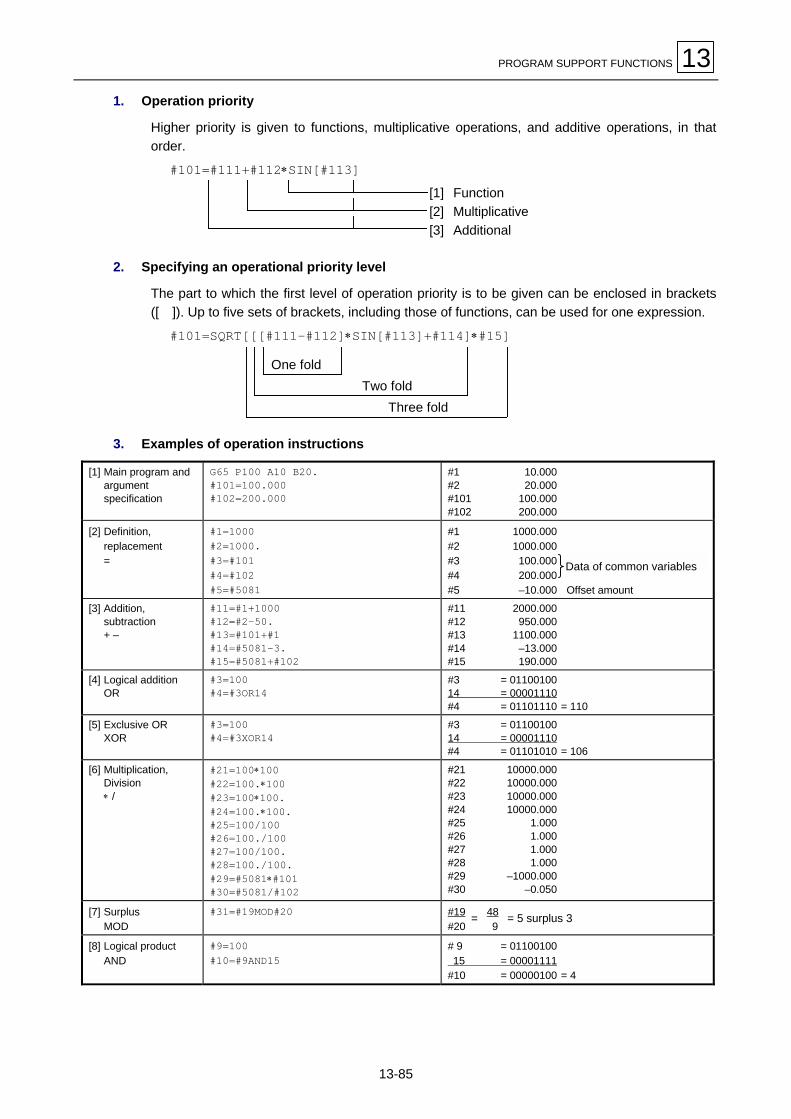
PROGRAM SUPPORT FUNCTIONS 13
13-85
1. Operation priority
Higher priority is given to functions, multiplicative operations, and additive operations, in thatorder.
#101=#111+#112∗SIN[#113][1] Function[2] Multiplicative[3] Additional
2. Specifying an operational priority level
The part to which the first level of operation priority is to be given can be enclosed in brackets([ ]). Up to five sets of brackets, including those of functions, can be used for one expression.
#101=SQRT[[[#111–#112]∗SIN[#113]+#114]∗#15]
One foldTwo fold
Three fold
3. Examples of operation instructions
[1] Main program andargumentspecification
G65 P100 A10 B20.#101=100.000#102=200.000
#1 10.000#2 20.000#101 100.000#102 200.000
[2] Definition,replacement=
#1=1000#2=1000.#3=#101#4=#102#5=#5081
#1 1000.000#2 1000.000#3 100.000#4 200.000#5 –10.000 Offset amount
[3] Addition,subtraction+ –
#11=#1+1000#12=#2–50.#13=#101+#1#14=#5081–3.#15=#5081+#102
#11 2000.000#12 950.000#13 1100.000#14 –13.000#15 190.000
[4] Logical additionOR
#3=100#4=#3OR14
#3 = 0110010014 = 00001110#4 = 01101110 = 110
[5] Exclusive ORXOR
#3=100#4=#3XOR14
#3 = 0110010014 = 00001110#4 = 01101010 = 106
[6] Multiplication,Division∗ /
#21=100∗100#22=100.∗100#23=100∗100.#24=100.∗100.#25=100/100#26=100./100#27=100/100.#28=100./100.#29=#5081∗#101#30=#5081/#102
#21 10000.000#22 10000.000#23 10000.000#24 10000.000#25 1.000#26 1.000#27 1.000#28 1.000#29 –1000.000#30 –0.050
[7] SurplusMOD
#31=#19MOD#20 #19 48#20 9
[8] Logical productAND
#9=100#10=#9AND15
# 9 = 01100100 15 = 00001111#10 = 00000100 = 4
Data of common variables
= 5 surplus 3=

13 PROGRAM SUPPORT FUNCTIONS
13-86
[9] SineSIN
#501=SIN[60]#502=SIN[60.]#503=1000∗SIN[60]#504=1000∗SIN[60.]#505=1000.∗SIN[60]#506=1000.∗SIN[60.]Note: SIN[60] is equal to SIN[60.].
#501 0.866#502 0.866#503 866.025#504 866.025#505 866.025#506 866.025
[10]CosineCOS
#541=COS[45]#542=COS[45.]#543=1000∗COS[45]#544=1000∗COS[45.]#545=1000.∗COS[45]#546=1000.∗COS[45.]Note: COS[45] is equal to COS[45.].
#541 0.707#542 0.707#543 707.107#544 707.107#545 707.107#546 707.107
[11]TangentTAN
#551=TAN[60]#552=TAN[60.]#553=1000∗TAN[60]#554=1000∗TAN[60.]#555=1000.∗TAN[60]#556=1000.∗TAN[60.]Note: TAN[60] is equal to TAN[60.].
#551 1.732#552 1.732#553 1732.051#554 1732.051#555 1732.051#556 1732.051
[12]Arc-tangentATAN
#561=ATAN[173205/1000000]#562=ATAN[173.205/100.]#563=ATAN[1.732]
#561 60.000#562 60.000#563 59.999
[13]Arc-cosineACOS
#521=ACOS[100000/141421]#522=ACOS[100./141.421]#523=ACOS[1000/1414.213]#524=ACOS[10./14.142]#525=ACOS[0.707]
#521 45.000#522 45.000#523 45.000#524 44.999#525 45.009
[14]Square rootSQRT
#571=SQRT[1000]#572=SQRT[1000.]#573=SQRT[10.∗10.+20.∗20.]#574=SQRT[#14∗#14+#15∗#15]Note: For enhanced accuracy, perform
operations within [ ] as far as possible.
#571 31.623#572 31.623#573 22.361#574 190.444
[15]Absolute valueABS
#576=–1000#577=ABS[#576]#3=70.#4=–50.#580= ABS[#4–#3]
#576 –1000.000#577 1000.000
#580 120.000
[16]BIN, BCD #1=100#11=BIN[#1]#12=BCD[#1]
#11 64#12 256
[17]Rounding into thenearest wholenumberROUND
#21=ROUND[14/3]#22=ROUND[14./3]#23=ROUND[14/3.]#24=ROUND[14./3.]#25=ROUND[–14/3]#26=ROUND[–14./3]#27=ROUND[–14/3.]#28=ROUND[–14./3.]
#21 5#22 5#23 5#24 5#25 –5#26 –5#27 –5#28 –5
[18]Cutting away anydecimal digitsFIX
#21=FIX[14/3]#22=FIX[14./3]#23=FIX[14/3.]#24=FIX[14./3.]#25=FIX[–14/3]#26=FIX[–14./3]#27=FIX[–14/3.]#28=FIX[–14./3.]
#21 4.000#22 4.000#23 4.000#24 4.000#25 –4.000#26 –4.000#27 –4.000#28 –4.000
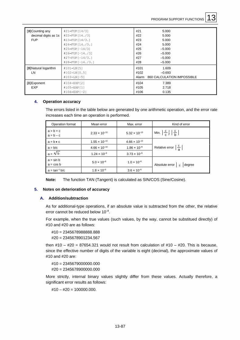
PROGRAM SUPPORT FUNCTIONS 13
13-87
[19]Counting anydecimal digits as 1sFUP
#21=FUP[14/3]#22=FUP[14./3]#23=FUP[14/3.]#24=FUP[14./3.]#25=FUP[–14/3]#26=FUP[–14./3]#27=FUP[–14/3.]#28=FUP[–14./3.]
#21 5.000#22 5.000#23 5.000#24 5.000#25 –5.000#26 –5.000#27 –5.000#28 –5.000
[20]Natural logarithmLN
#101=LN[5]#102=LN[0.5]#103=LN[–5]
#101 1.609#102 –0.693Alarm 860 CALCULATION IMPOSSIBLE
[21]ExponentEXP
#104=EXP[2]#105=EXP[1]#106=EXP[–2]
#104 7.389#105 2.718#106 0.135
4. Operation accuracy
The errors listed in the table below are generated by one arithmetic operation, and the error rateincreases each time an operation is performed.
Operation format Mean error Max. error Kind of error
a = b + ca = b – c
2.33 × 10⁻¹⁰ 5.32 × 10⁻¹⁰ Min. εc , ε
b
a = b • c 1.55 × 10⁻¹⁰ 4.66 × 10⁻¹⁰
a = b/c 4.66 × 10⁻¹⁰ 1.86 × 10⁻⁹
a = b 1.24 × 10⁻⁹ 3.73 × 10⁻⁹
Relative error εa
a = sin ba = cos b
5.0 × 10⁻⁹ 1.0 × 10⁻⁸
a = tan–1 b/c 1.8 × 10⁻⁶ 3.6 × 10⁻⁶
Absolute error ε degree
Note: The function TAN (Tangent) is calculated as SIN/COS (Sine/Cosine).
5. Notes on deterioration of accuracy
A. Addition/subtraction
As for additional-type operations, if an absolute value is subtracted from the other, the relativeerror cannot be reduced below 10–8.
For example, when the true values (such values, by the way, cannot be substitued directly) of#10 and #20 are as follows:
#10 = 2345678988888.888#20 = 2345678901234.567
then #10 – #20 = 87654.321 would not result from calculation of #10 – #20. This is because,since the effective number of digits of the variable is eight (decimal), the approximate values of#10 and #20 are:
#10 = 2345679000000.000#20 = 2345678900000.000
More strictly, internal binary values slightly differ from these values. Actually therefore, asignificant error results as follows:
#10 – #20 = 100000.000.

13 PROGRAM SUPPORT FUNCTIONS
13-88
B. Logical relationship
As for EQ, NE, GT, LT, GE and LE, the processing is executed in a similar manner to additionand substraction, so be careful to errors. For example, to judge whether #10 is equal to #20 ofthe above example, the conditional expression
IF [#10EQ#20]
is not appropriate due to the errors. In such a case, therefore, give a macro-instruction as shownbelow to allow for an acceptable tolerance in the judgement on the equality of two values.
IF [ABS[#10 – #20] LT200000]
C. Trigonometric functions
For trigonometric functions, although the absolute error is guaranteed, the relative error is notbelow 10–8. Be careful, therefore, when carrying out multiplication, or division after trigonometricfunction operations.
13-9-6 Control commands
The flow of a program can be controlled using IF ∼ GOTO ∼ and WHILE DO ∼ commands.
1. Branching
Format: IF [conditional expression] GOTO n
where n is a sequence number in the same program.The branching will occur to the block headed by sequence number ‘n’ if the condition holds, or ifthe condition does not hold, the next block will be executed.An independent setting of GOTO statement without IF [conditional expression] will performunconditional branching to the specified block.
The [conditional expression] consists of the following six types:
#i EQ #j = ( #i is equal to #j.)
#I NE #j ≠ (#i is not equal to #j.)
#i GT #j > (#i is larger than #j.)
#I LT #j < (#i is smaller than #j.)
#I GE #j ≥ (#i is equal to #j, or larger than #j.)
#I LE #j ≤ (#i is equal to #j, or smaller than #j.)
For GOTO n, n must be a sequence number within the same program. If the sequence numberdoes not exist in that program, an alarm 843 DESIGNATED SNo. NOT FOUND will occur. Anexpression or a variable can be used instead of #i, #j, or n.Sequence number designation Nn must be set at the beginning of the destination block.Otherwise, an alarm 843 DESIGNATED SNo. NOT FOUND will result. If, however, the blockbegins with “/” and Nn follows, the program can be branched into that sequence number.

PROGRAM SUPPORT FUNCTIONS 13
13-89
N10 #22=#20 #23=#21IF[#2EQ1] GOTO100#22=#20–#3#23=#21–#4
N100 X#22 Y#23#1=#1+1
Branching to N100if #2 = 1. Search
forN10to becon-
tinuedback to
thehead
Searchfor
N100
Note: During search for the branching destination sequence number, if the area from theblock after “IF ...” to the program end (% code) is searched (forward search) in vain,then the area from the head down to the block before “IF ...” will be searched next(backward search). It will therefore take more time to execute backward search(searching in the opposite direction to the flow of the program) than to execute forwardsearch.
2. Looping
Format:WHILE [Condition expression] DOm (m = 1, 2, 3 $$$ 127)
ENDm
The area from the next block to the ENDm block loops while the conditional expression holds. Ifthe conditional expression does not hold, control will be tansferred to the block after ENDm. Inthe format shown above, DOm can precede WHILE.You must always use WHILE [conditional expression] DOm and ENDm in pairs. If you omitWHILE [conditional expression], the area from DOm to ENDm will endlessly loop. In DOm, m (1to 127) identifies the number of looping. (DO1, DO2, DO3, and so on up to DO127)The maximum available number of degrees of multiplicity is 27.

13 PROGRAM SUPPORT FUNCTIONS
13-90
[1] Same identifying No. can be used repeatedly.
END1
END1
WHILE ∼ DO1
WHILE ∼ DO1
Usable
Usable
[2] The identifying No. of WHILE ∼ DOm is arbitrary.
END1
WHILE ∼ DO1
END3
WHILE ∼ DO3
END2
WHILE ∼ DO2
END1
WHILE ∼ DO1
Usable
[3] Up to 27 levels of WHILE ∼ DOm can be used.
m can be 1 to 127, independent of the depth of nesting.
WHILE ∼ DO1
WHILE ∼ DO2 MWHILE ∼ DO27
END27 MEND2
END1
Usable
DO1
DO2 % % %
DO27
Note: For nesting, m once used cannot be used again.
[4] The total number of levels of WHILE ∼ DOm must not
exceed 27.
Unusable
WHILE ∼ DO1WHILE ∼ DO2
WHILE ∼ DO27
WHILE ∼ DO28
END28
END27
END2END1
M
M
[5] WHILE ∼ DOm must precede ENDm.
Unusable
WHILE ∼ DO1
END1
[6] WHILE ∼ DOm must correspond to ENDm one-to-one in thesame program.
WHILE ∼ DO1
WHILE ∼ DO1
END1
Unusable
[7] WHILE ∼ DOm must not overlap.
Unusable
WHILE ∼ DO1
END1
WHILE ∼ DO2
END2
[8] Outward branching from the range of WHILE ∼ DOm ispossible.
WHILE ∼ DO1
IF ∼ GOTOn
END1
Nn$$$$$$$$
Usable

PROGRAM SUPPORT FUNCTIONS 13
13-91
[9] Branching into WHILE ∼ DOm is not allowed.
IF ∼ GOTOn
WHILE ∼ DO1
END1
Nn$$$$$$$$
END1
WHILE ∼ DO1
Nn$$$$$$$$
END1
IF ∼ GOTOn
Unusable
WHILE ∼ DO1
Unusable
[10] Subprogram can be called using M98, G65, G66, etc. fromthe midway of WHILE ∼ DOm.
G65 P100
END1M02
Usable
Main program Subprogram
WHILE ∼ DO2
END2
M99
To sub-program
WHILE ∼ DO1
[11] The looping can be independently programmed in asubprogram which is called using G65/G66 from themidway of WHILE ∼ DOm. Up to 27 levels of nesting forboth programs can be done.
END1
UsableG65 P100
Main program Subprogram
WHILE ∼ DO1
END1
M99
WHILE ∼ DO1
To sub-program
[12] If WHILE and END are not included in pairs in subprogram(including macro subprogram), a program error will result atM99.
M02
M65 P100
Main program Subprogram
M99
WHILE ∼ DO1
Alarm 868 DO-END MIS-MATCH

13 PROGRAM SUPPORT FUNCTIONS
13-92
13-9-7 External output commands (Output via RS-232C)
1. Overview
In addition to standard user macros, the types of macros listed below are provided as externaloutput commands. These external output macros can be used to output character data or thenumerical data in variables to an external unit via an RS-232C interface. The data are outputtedin a data length of 7 bits with an even-parity bit added.
A. Types and functions of external output macros
POPEN Setup processing for data output
PCLOS Termination processing of data output
BPRNT Printout of character data or binary printout of variable data
DPRNT Printout of character data or numerical printout of variable data on a digit-by-digitbasis
B. Programming order
Close command
Data output commands
Open command
BPRNT
POPEN
DPRNT
PCLOS
2. Open command POPEN
Programming format: POPEN
Detailed description
- The command code POPEN must be included before a series of data output command codes.
- The control code for DC2 and the percentage code % are output from the NC unit to anexternal output unit.
- Once POPEN has been set, it will remain valid until PCLOS is set.
3. Close command PCLOS
Programming format: PCLOS
Detailed description
- The command code PCLOS must be included after all data output command codes.
- The control code for DC4 and the percentage code % are outputted from the NC unit to anexternal output unit.
- This command must be used together with POPEN. This command code must be included onlyafter POPEN.
- This command must be set at the end of the program even after data output has been abortedusing, for example, the NC reset switch.

PROGRAM SUPPORT FUNCTIONS 13
13-93
4. Data output command BPRNT
Programming format:
BPRNT[l1#v1[c1]l2#v2[c2]$$$$$$$$]
Variable value× 10c
Effective digits after decimal pointVariable numberCharacter string
Detailed description
- The command BPRNT can be used to output characters or to output variable data in binaryform.
- The designated character string is outputted directly in the ISO coded format. Alphanumerics(A to Z, and 0 to 9) and/or special characters (+, –, ∗, /) can be used. Of these characters, onlythe asterisk (∗) is outputted as a space code.
- Since all variables are saved as those having a decimal point, the necessary number ofdecimal digits must be enclosed in brackets ([ ]).All variables are handled as data of four bytes (32 bits), and each byte is outputted as binarydata in the order of the most significant byte first. Minus data is processed as the complementfor that data.Example 1: If three digits are specified for 12.3456, then
[12.346 × 10³] = 12346 (0000303A)will be outputted as binary data.
Example 2: If no digits are specified for –100.0, then–100 (FFFFFF9C)will be outputted as binary data.
- After the specified data has been outputted, the EOB (End Of Block) code is outputted in theformat of the appropriate ISO code.
- Variables containing <empty> are interpreted as 0s.
5. Data output command DPRNT
Programming format:
DPRNT[l1#v1[d1 c1]l2#v2[c2]LL]
c + d ≤ 8Effective digits below decimal pointEffective digits above decimal pointVariable numberCharacter string
Detailed description
- Output of character data or decimal output of variable data is performed in the format of ISOcodes.
- The designated character string is outputted directly in the ISO coded format.Alphanumerics (A to Z, and 0 to 9) and/or special characters (+, –, ∗, /) can be used. Of thesecharacters, only the asterisk (∗) is outputted as a space code.
- Of the data contained in a variable, the necessary number of digits above the decimal point andthat of digits below the decimal point must each be enclosed in brackets ([ ]). The variabledata will then have its total specified number of digits, including the decimal point, outputted inthe ISO coded format in the order of the most significant digit first. No trailing zeros will be leftout in that case.

13 PROGRAM SUPPORT FUNCTIONS
13-94
13-9-8 External output command (Output onto the hard disk)
1. Overview
External output macros can also be used to output data in text file format into the predetermineddirectory on the hard disk.
2. Related parameters
- DPR14: Selection of an output destination portSet DPR14 to “4” (Output onto the hard disk) under OTHER on the DATA I/O PARAMETERdisplay.
- DPR15: Number of lines in feed sectionSet the required number of lines to be fed.
- DPR8: Output file sizeUse this parameter to specify the maximum permissible output file size.
Maximum permissible file size: DPR8 × 100 (KB)
A command for outputting a greater file will cause a corresponding alarm.
However, the file size limit is 100 KB if the value in DPR8 is 0.
Note: Output of a file of smaller size than the limit, however, may not be possible due to ashortage of available area on the hard disk.
The DATA I/O PARAMETER display can be selected by pressing the [DATA I/O PARAM.]menu key on the DATA I/O display.
See the Parameter List for details of the parameters.
3. Output file
The text file will be automatically outputted with a particular file name into the predetermineddirectory.
Output directory: c:\MC_sdg\print\
Output file name: print.txt(A file of this name will be automatically created, if required, or the text datawill be added to the current contents of the file.)
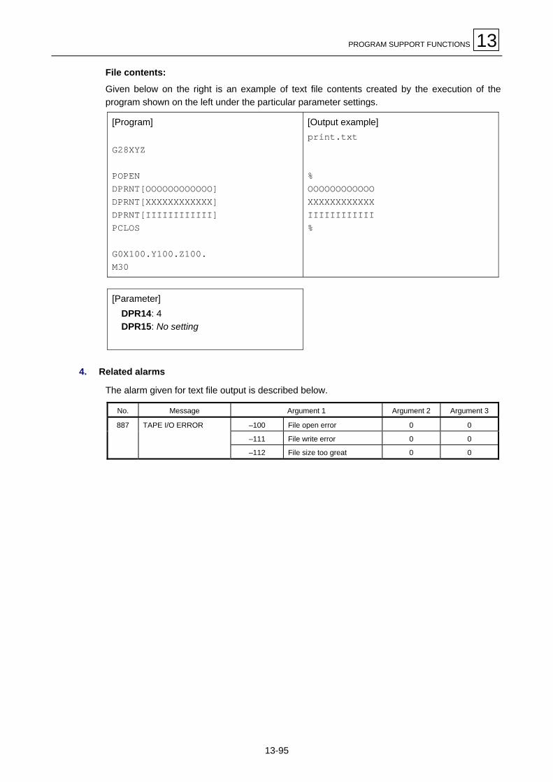
PROGRAM SUPPORT FUNCTIONS 13
13-95
File contents:
Given below on the right is an example of text file contents created by the execution of theprogram shown on the left under the particular parameter settings.
[Program]
G28XYZ
POPENDPRNT[OOOOOOOOOOOO]DPRNT[XXXXXXXXXXXX]DPRNT[IIIIIIIIIIII]PCLOS
G0X100.Y100.Z100.M30
[Output example]print.txt
%OOOOOOOOOOOOXXXXXXXXXXXXIIIIIIIIIIII%
[Parameter] DPR14: 4 DPR15: No setting
4. Related alarms
The alarm given for text file output is described below.
No. Message Argument 1 Argument 2 Argument 3
–100 File open error 0 0
–111 File write error 0 0
887 TAPE I/O ERROR
–112 File size too great 0 0

13 PROGRAM SUPPORT FUNCTIONS
13-96
13-9-9 Precautions
Use of user macro commands allows a machining program to be created by combining arithmeticoperation, judgment, branchining, or other macro commands with conventional NC commandssuch as move commands, M-, S-, T-commands, etc. The statement defined by these macrocommands and that of conventional NC commands are taken as a macro statement and an NCexecute statement, respectively. The treatment of a macro statement has no direct rerations withmachine control. Its treatment as short as possible is effective for shortening machining time.Parallel processing of the NC execute statement and the macro statement becomes possibleaccording to the setting of bit 6 of parameter F93.(It becomes possible to process all macro statements in batch form by setting the parameter bitto OFF when machining the workpiece, or to execute the macro statements block-by-block bysetting the parameter bit to ON when checking the program. Therefore, set the parameter bitaccording to your requirements.)
Sample programN1 G91G28X0Y0Z0N2 G92X0Y0Z0N3 G00X–100.Y–100.N4 #101=100.∗COS[210.]N5 #102=100.∗SIN[210.]N6 G01X#101Y#102F800
A macro statement refers to a statement that consists of the following blocks:
- Arithmetic operation command block (compassing the equal sign =)
- Control command block (compassing GOTO, DO ∼ END, etc.)
- Macro call command block (compassing macro call or cancellation G-code commands G65,G66, G66.1, or G67)
An NC execute statement refers to a non-macro statement.
Macro statements

PROGRAM SUPPORT FUNCTIONS 13
13-97
The flow of processing of these two types of statements is shown below.
ParameterOFF
ParameterON
Machining program data is displayed as follows:
ParameterOFF
(In execution) N3 G00X–100.Y–100.(Next command) N6 G01X#101Y#102F800
N4, N5 and N6 are treated in parallel with NCexecution sentence of N3, and N6 is displayed asnext command because it is NC executionsentence. When N4, N5, and N6 are analizedduring NC execution sentence of N3, machinecontrol continues.
ParameterON
(In execution) N3 G00X–100.Y–100.(Next command) N4 #101=100.∗COS[210.]
N4 is treated in parallel with the control of NCexecution sentence of N3, and is displayed asnext command.After N3 is completed, N5 and N6 are analized sothe machine control is forced to wait by theanalyzing time of N5 and N6 before N6 can beexecuted.
Macroprogram statementtreatment
NC statementtreatment
Next command
Program analysis
In execution
N1 N2 N3 N4 N5 N6 N7
N4 N5
N2 N3 N6 N7
N1 N2 N3 N6
N1 N2 N3 N4 N5 N6 N7
N4 N5
N2 N3 N4 N7
N1 N2 N3 N6
Macroprogram statementtreatment
NC statementtreatment
Next command
Program analysis
In execution

13 PROGRAM SUPPORT FUNCTIONS
13-98
13-9-10 Specific examples of programming using user macros
The following three examples of programming are shown here:
Example 1: SIN curveExample 2: Bolt-hole circleExample 3: Grid
Example 1: SIN curve
MEP172
A: Initial value 0°B: Final value 360°C: R of R∗SINθF: Feed rate
(sin θ)Y
0 90. 180. 270. 360.
X
–100.
100.G65 Pp1 Aa1 Bb1 Cc1 Ff1
To subprogram
MG65P9910A0B360.C100.F100 M
WHILE[#1LE#2]DO1#10=#3∗SIN[#1]G90G1X#1Y#10F#9#1=#1+10.END1M99
Note
O9910 (Subprogram)Main program
Note: G90G01X#1Y[#3∗SIN[#1]]F#9makes one block command available.
Local variable setin argument
#1 = 0#2 = 360.000#3 = 100.000#9 = 100.000

PROGRAM SUPPORT FUNCTIONS 13
13-99
Example 2: Bolt-hole circleAfter hole data has been defined using fixed-cycle machining commands G72 toG89, hole positions are to be designated using macro commands.
G81Z–100.R50.F300G65P9920Aa1Bb1Rr1Xx1Yy1
Main program
To subprogram
#120 = Hole position X coordinate#121 = Hole position Y coordinate#122 = X-axis absolute value#123 = Y-axis absolute value
a1 : Start angleb1 : Hole quantityr1 : Radiusx1 : X-axis center positiony1 : Y-axis center position
–X x1
y1
W
–Y
a1
MEP173
0 → #101G90,G91 - Read-in
→ #102Preceding coordinateread-in
X → #103Y → #104
Start angle → #111
#101 ≤ Holequantity
#102 = 90
N100X#122Y#123
No
Yes
Yes
No
#101 = Hole count
#102 = G90 or G91
#103 = X-axis present position#104 = Y-axis present position#111 = Start angle
Mode judge G90, G91
Note:The processing time can be reduced byone-block reduced programming.
Hole number count-up
#111 = Hole position angle
Radius∗COS [#111]+ center coordinate X → #120Radius∗SIN [#111]+ center coordinate Y → #121#120 → #122#121 → #123
#120 – #103 → #122
#121 – #104 → #123
#120 → #103
#121 → #104
Y
#122 = X-axis incremental value
#123 = Y-axis incremental value
X-axis present position renewal
Y-axis present position renewal
Drilling command
#101+1 → #101
360°∗#101/Hole quantity
+ #1 → #111
O9920
END
O9920 (Subprogram)
#101=0#102=#4003#103=#5001#104=#5002#111=#1
WHILE[#101LT#2]DO1
#120=#24+#18∗COS[#111]#121=#25+#18∗SIN[#111]
#122=#120 #123=#121IF[#102EQ90]GOTO100
#122=#120–#103#123=#121–#104
#103=#120#104=#121
N100 X#122Y#123#101=#101+1#111=#1+360.∗#101/#2
END1M99
Note
Note
Note
Note
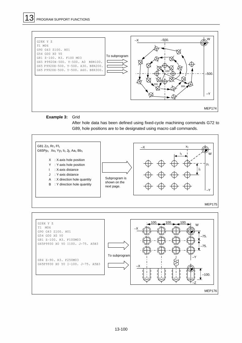
13 PROGRAM SUPPORT FUNCTIONS
13-100
MEP174
–500.
G28X Y ZT1 M06G90 G43 Z100. H01G54 G00 X0 Y0G81 Z-100. R3. F100 M03G65 P9920X-500. Y-500. A0 B8R100.G65 P9920X-500. Y-500. A30. B8R200.G65 P9920X-500. Y-500. A60. B8R300.
–X –500. W
–Y
100.
300.200.
To subprogram
Example 3: GridAfter hole data has been defined using fixed-cycle machining commands G72 toG89, hole positions are to be designated using macro call commands.
MEP175
Subprogram isshown on thenext page.
G81 Zz1 Rr1 Ff1G65Pp1 Xx1 Yy1 Ii1 Jj1 Aa1 Bb1
X : X-axis hole positionY : Y-axis hole positionI : X-axis distanceJ : Y-axis distanceA : X direction hole quantityB : Y direction hole quantity
–Y
y1
j1
W
x1–X
i1
To subprogram
G28X Y ZT1 M06G90 G43 Z100. H01G54 G00 X0 Y0G81 Z–100. R3. F100M03G65P9930 X0 Y0 I100. J–75. A5B3
G84 Z–90. R3. F250M03G65P9930 X0 Y0 I–100. J–75. A5B3
100. 100. 100.
–75.
W
–75.
–Y
–100.
–Z
–X
–X
MEP176

PROGRAM SUPPORT FUNCTIONS 13
13-101
#101 = X-axis start point#102 = Y-axis start point#104 = Y direction distance#105 = X-axis hole quanty#106 = Y-axis hole quantity – 1#110 = Y direction line count#111 = Even/odd times judge#112 = X-asis drilling direction
reverse switch
#101=#24#102=#25#104=#10#105=#1#106=#2–1#110=0#111=0#112=0
N2 #113=0#103=#9
WHILE[#105GT0]DO1#101=#101+#113#105=#105–1X#101Y#102
IF[#112EQ1]GOTO10IF[#111NE1]GOTO10
#103=0–#103#112=1
N10 #113=#103END1
N100 #106=#106–1#112=0#110=#110+1
IF[#106LT0]GOTO200
#105=#1#102=#102+#104#111=#110
#111=#111AND1
GOTO2
N200 M99
O9930 (Subprogram)
Note:The processing time can be reduced by one-block reduced programming.
Note
Note
Note
Note
Note
Note
Y direction hole drillingcompletion check
Start point X coordinate → #101Start point Y coordinate → #102Y-axis direction distance → #104X-axis hole quantity → #105Y-axis hole quantity –1 → #106
0 → #1100 → #1110 → #112
#105 > 0No
Yes
O9930
0 → #113X direction distance → #103
#112 = 1
#101 + #113 → #101#105 –1 → #105
Yes
#111 = 1
X-axis drilling direction reverseswitch check
No
Yes
0 – #103 → #1031 → #112
#103 → #113
#106 – 1 → #1060 → #112#110 + 1 → #110
#106 < 0Yes
No
#1 → #105#102 + #104 → #102#110 → #111#111AND 1 → #111
X#101 Y#102
For even times (#111 = 0), Xdistance is same as command.For odd times (#111 = 1), X-axisdrilling direction reverse switch on
No
#113 = X-axis distance initial#103 = X direction distance
X coordinates renewalX direction hole quantity – 1
X direction hole drillingcompletion check
Drilling command
X-axis drilling distance reset
Y-axis hole quantity – 1X-axis drilling direction reverse switch onY direction line count-up off
X-axis hole quantity resetY coordinates renewal
Even times = 0Odd times = 1
N2
N10
N100
END
N100
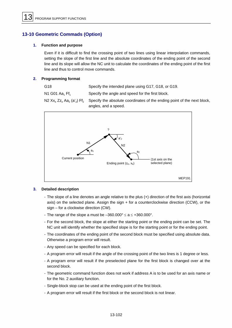
13 PROGRAM SUPPORT FUNCTIONS
13-102
13-10 Geometric Commads (Option)
1. Function and purpose
Even if it is difficult to find the crossing point of two lines using linear interpolation commands,setting the slope of the first line and the absolute coordinates of the ending point of the secondline and its slope will allow the NC unit to calculate the coordinates of the ending point of the firstline and thus to control move commands.
2. Programming format
G18 Specify the intended plane using G17, G18, or G19.
N1 G01 Aa1 Ff1 Specify the angle and speed for the first block.
N2 Xxe Zze Aa2 (a’2) Ff2 Specify the absolute coordinates of the ending point of the next block,angles, and a speed.
a2
Ending point (ze, xe)
N2
a’2
?
N1
a1
Current position (1st axis on theselected plane)
MEP191
3. Detailed description
- The slope of a line denotes an angle relative to the plus (+) direction of the first axis (horizontalaxis) on the selected plane. Assign the sign + for a counterclockwise direction (CCW), or thesign – for a clockwise direction (CW).
- The range of the slope a must be –360.000° ≤ a ≤ +360.000°.
- For the second block, the slope at either the starting point or the ending point can be set. TheNC unit will identify whether the specified slope is for the starting point or for the ending point.
- The coordinates of the ending point of the second block must be specified using absolute data.Otherwise a program error will result.
- Any speed can be specified for each block.
- A program error will result if the angle of the crossing point of the two lines is 1 degree or less.
- A program error will result if the preselected plane for the first block is changed over at thesecond block.
- The geometric command function does not work if address A is to be used for an axis name orfor the No. 2 auxiliary function.
- Single-block stop can be used at the ending point of the first block.
- A program error will result if the first block or the second block is not linear.

PROGRAM SUPPORT FUNCTIONS 13
13-103
4. Correlationships to other functions
Geometric command can be set following a linear angle command.
N1Xx2Aa1N2Aa2N3Xx3Zz3Aa3
MEP192
(x3, z3)
(x2, z2)
(x1, z1)
N1
N2
N3
?
a1
a3
a2
13-11 Corner Chamfering and Corner Rounding Commands
Automatic chamfering (or rounding) at any angle becomes possible by adding characters “,C_”or “, R_” at the end of the first block of the two blocks that use only lines to generate corners.
13-11-1 Corner chamfering ( , C_)
1. Function and purpose
The sections before and after virtual corners, for which it is assumed that no chamfering is totake place, are chamfered over a distance which is specified in C_.
2. Programming format
N100 G01 X_Y_, C_
N200 G01 X_Y_
Distance from the virtual corner to the starting or ending point ofchamfering
Chamfering will be executed at the crossing point of N100 andN200.

13 PROGRAM SUPPORT FUNCTIONS
13-104
3. Sample program
[1] G91G01X100.,C10.[2] X100.Y100.
Y-axis
Y100.0
X100.0X100.0
10.0
10.0
[2]
[1]
Chamferingending point
X-axis
Virtual cornercrossing point
Chamferingstarting point
MEP193
4. Detailed description
- The starting point of the next block of corner chamfering is a virtual corner crossing point.
- If character C is not preceded by a comma (,), that command will be regarded as a C-codecommand.
- If one block contains both “, C_” and “, R_”, only the last issued command will become valid.
- Tool offset data is calculated for the shape existing after completion of corner chamfering.
- Scaling, if already set, also works for the amount of corner chamfering.
- Alarm 912 NO MOTION COMMAND AFTER R/C results if the command in the blockimmediately succeeding that of the corner-chamfering command is not a linear-machiningcommand.
- Alarm 913 INCORRECT R/C COMMAND results if the distance of movement, specified in thecorner-chamfering command block, is less than the amount of chamfering.
- Alarm 914 INCORRECT COMMAND AFTER R/C results if the distance of movement,specified in the block immediately succeeding the corner chamfering command block, is lessthan the amount of chamfering.
- Alarm 911 CORNER R/C OPTION NOT FOUND results if the command in the blockimmediately succeeding that of the corner chamfering command is an arc-machiningcommand.

PROGRAM SUPPORT FUNCTIONS 13
13-105
13-11-2 Corner rounding ( ,R_)
1. Function and purpose
The virtual corners to be used when it is assumed that no corner rounding is to take place for thecorners that each consist of only lines, are rounded using the arcs whose radii are specifiedusing R_.
2. Programming format
N100 G01 X_Y_,R_
N200 G01 X_Y_
3. Sample program
[1] G91G01X100.,R10.[2] X100.Y100.
MEP194
Y-axis
Y100.0
X100.0X100.0
[2]
[1]
X-axis
R10.0
Corner roundingstarting point
Corner roundingending point
Virtual cornercrossing point
Radius of the arc for corner rounding
Rounding will be executed at the crossing point ofN100 and N200.

13 PROGRAM SUPPORT FUNCTIONS
13-106
4. Detailed description
- The starting point of the next block of corner rounding is a virtual corner crossing point.
- If character R is not preceded by a comma (,), that command will be regarded as an R-codecommand.
- If one block contains both “, C_” and “, R_”, only the last issued command will become valid.
- Tool offset data is calculated for the shape existing after completion of corner rounding.
- Scaling, if already set, also works for the amount of corner rounding.
- Alarm 912 NO MOTION COMMAND AFTER R/C results if the command in the blockimmediately succeeding that of the corner-rounding command is not a linear-machiningcommand.
- Alarm 913 INCORRECT R/C COMMAND results if the distance of movement, specified in thecorner-rounding command block, is less than the amount of rounding.
- Alarm 914 INCORRECT COMMAND AFTER R/C results if the distance of movement,specified in the block immediately succeeding the corner-rounding command block, is less thanthe amount of rounding.
- Alarm 911 CORNER R/C OPTION NOT FOUND results if the command in the blockimmediately succeeding that of the corner-rounding command is an arc-machining command.
E

COORDINATE SYSTEM SETTING FUNCTIONS 14
14-1
14 COORDINATE SYSTEM SETTING FUNCTIONS
14-1 Fundamental Machine Coordinate System, Workpiece Coordinate Systems,and Local Coordinate Systems
The fundamental machine coordinate system, which is a fixed coordinate system for the machine,is used to designate the tool change position, stroke end position, etc. that are predetermined forthe machine.Workpiece coordinate systems are the coordinate systems to be used by a programmer whencreating programs. These coordinate systems have their origins set at reference points onworkpieces. Local coordinate systems are the coordinate systems to be set on the workpiececoordinate systems to facilitate the creating of partial-machining programs.
M
W1 W2R#1
R#1
M
W1 to W4: Workpiece coordinate system 1 to 4
Fundamental machine coordinate system
Local coordinate system
(1st) reference point
MEP195
W4
W2W1
W3

14 COORDINATE SYSTEM SETTING FUNCTIONS
14-2
14-2 Machine Zero Point and Second, Third, and Fourth Reference Points
The machine zero point refers to a position that acts as a reference point for the fundamentalmachine coordinate system. That is, the machine zero point is a point specific to the machine,determined by return to the reference point (zero point).
The second, third, and fourth reference points (zero point) are the points whose positions in thefundamental machine coordinate system are parameter-preset.
x
y
y
y
x
(X1, Y1)(X2, Y2)
Workpiece coordinate system (G54 to G59)
Local coordinatesystem (G52)
3rd ref. point
2nd ref. point
1st ref. point
Fundamental machinecoordinate system (G53)
Machine zero point
4th ref. point
x
MEP196

COORDINATE SYSTEM SETTING FUNCTIONS 14
14-3
14-3 Fundamental Machine Coordinate System Selection: G53
1. Function and purpose
The fundamental machine coordinate system is used to designate the tool change position,stroke end position, etc. that are predetermined for the machine.Command G53 and its succeeding coordinate words move the tool at the rate of rapid traverse tothe designated position on the fundamental machine coordinate system.
2. Programming format
Selection of the fundamental machine coordinate system:(G90) G53 Xx Yy Zz αα (α: Additional axis)
3. Detailed description
- When power is turned on, the fundamental machine coordinate system will be set according tothe reference point (zero point) return position which is determined by a manual or automaticreference point (zero point) return command.
- The fundamental machine coordinate system is not updated by command G92.
- Command G53 is valid only for designated blocks.
- During the incremental data command mode (G91), command G53 moves the tool on theselected coordinate system according to incremental data.
- Setting of command G53 does not cancel the tool diameter offset data of the designated axis.
- The coordinate data of the first reference point represents the distance from point 0 on thefundamental machine coordinate system to the reference point (zero point) return position.
M–X
–Y
R#1
(500, 500)
Reference point (zero point)return position (#1)
Zero point of the fundamentalmachine coordinate system
First reference point coordinate values: X = +500Y = +500
MEP197

14 COORDINATE SYSTEM SETTING FUNCTIONS
14-4
14-4 Coordinate System Setting: G92
1. Function and purpose
Setting of command G92 allows absolute coordinate system and current position display data tobe newly preset exactly as programmed, without ever having to move the machine.
2. Programming format
G92 Xx1 Yy1 Zz1 αα1 (α: Additional axis)
3. Detailed description
- After power-on, return to the reference point is initially performed using watchdogs. Coordinatesystems are set automatically on completion of return.
MEP198
R
W(G54) 100. 200. 300.
[M-Pos.] X 0.000 Y 0.000
[W-Pos.] X 300.000 Y 200.000
100.
R, M
Power-onposition
WorkpieceCoordinate system
Power-onposition
Referencepoint return
Referencepoint returncompletion
Fundamental machine coordinate system
M-Pos. : Current position in the Machine coordinate systemW-Pos. : Current position in the Workpiece coordinate system
Fundamental machine and workpiece coordinate systems are established at predeterminedpositions.
- Setting of command G92 allows absolute (workpiece) coordinate system and current positiondisplay data to be newly preset exactly as programmed, without ever having to move themachine.
W(G54)
Tool
Tool
100. 200. 300.
100.
P(G54') 200.
100.
200.
100.–50.
W(G54)
50.
R, MR, M
[M-Pos.]X 0.000Y 0.000[W-Pos.]X 0.000Y 0.000
[M-Pos.]X –200.000Y –150.000
[W-Pos.]X 100.000Y 50.000
–100.
For example, if G92X0Y0; is set, a new workpiece coordinate system will be established.
Coordinatesystem setting
MEP199

COORDINATE SYSTEM SETTING FUNCTIONS 14
14-5
14-5 Automatic Coordinate System Setting
The automatic coordinate system setting function allows various coordinate systems to begenerated according to parameters previously set on the operation panel when the first manualreference point return or watchdog-based reference point return is completed.Use the automatically set coordinate systems when creating machining programs.
MEP200
y2
x2
y4
x4
y3
x3
x1
y1
W1 (G54)
W4 (G57)
W2 (G55)
W5 (G58)
W3 (G56)
W6 (G59)
First referencepoint
Machine zero pointFundamental machine coordinates system (G53)
- This function generates the following coordinate systems:
1) Fundamental machine coordinate system (G53)
2) Workpiece coordinate systems (G54 through G59)
- Parameters for the NC unit must be the distance data from the origin of the fundamentalmachine coordinate system. You must therefore determine where on the fundamental machinecoordinate system the first reference point is to be set, and then set the zero point of theworkpiece coordinate system.
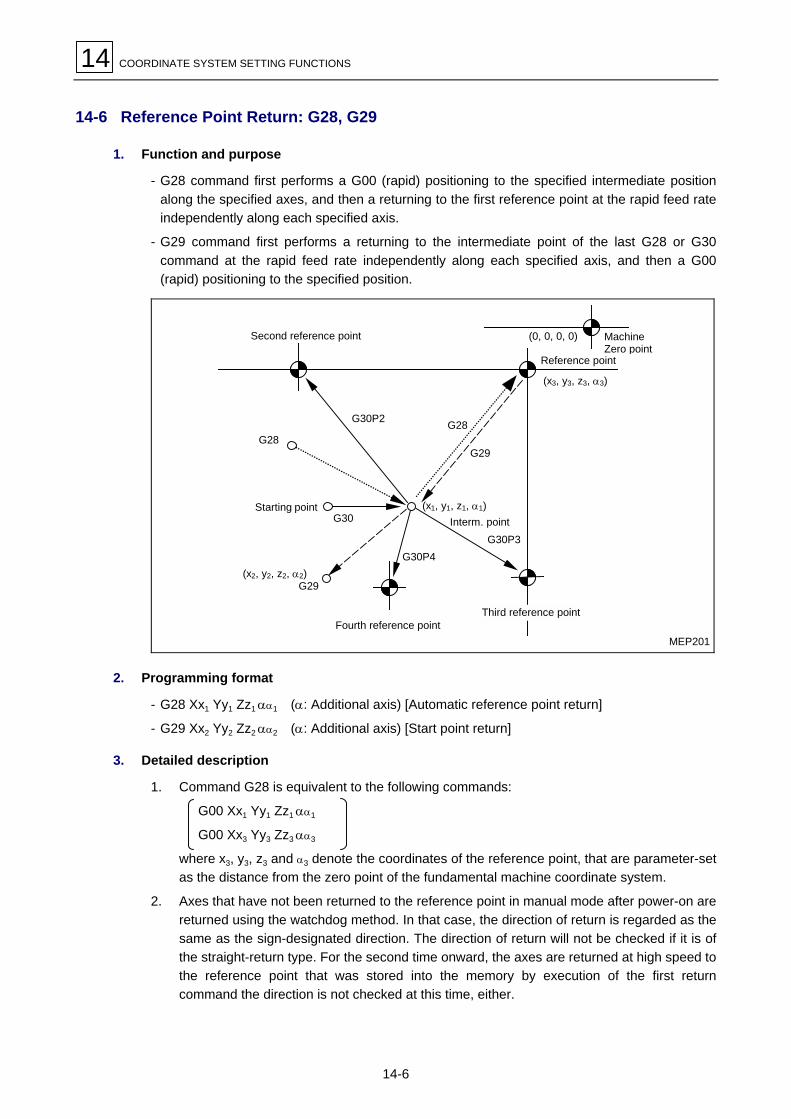
14 COORDINATE SYSTEM SETTING FUNCTIONS
14-6
14-6 Reference Point Return: G28, G29
1. Function and purpose
- G28 command first performs a G00 (rapid) positioning to the specified intermediate positionalong the specified axes, and then a returning to the first reference point at the rapid feed rateindependently along each specified axis.
- G29 command first performs a returning to the intermediate point of the last G28 or G30command at the rapid feed rate independently along each specified axis, and then a G00(rapid) positioning to the specified position.
MEP201
G30P4
G29(x2, y2, z2, α2)
G30
G28
G30P2 G28
G29
G30P3
(x1, y1, z1, α1)
(x3, y3, z3, α3)
(0, 0, 0, 0)
Fourth reference point
Starting pointInterm. point
Third reference point
Second reference point MachineZero point
Reference point
2. Programming format
- G28 Xx1 Yy1 Zz1 αα1 (α: Additional axis) [Automatic reference point return]
- G29 Xx2 Yy2 Zz2 αα2 (α: Additional axis) [Start point return]
3. Detailed description
1. Command G28 is equivalent to the following commands:
G00 Xx1 Yy1 Zz1 αα1
G00 Xx3 Yy3 Zz3 αα3
where x3, y3, z3 and α3 denote the coordinates of the reference point, that are parameter-setas the distance from the zero point of the fundamental machine coordinate system.
2. Axes that have not been returned to the reference point in manual mode after power-on arereturned using the watchdog method. In that case, the direction of return is regarded as thesame as the sign-designated direction. The direction of return will not be checked if it is ofthe straight-return type. For the second time onward, the axes are returned at high speed tothe reference point that was stored into the memory by execution of the first returncommand the direction is not checked at this time, either.

COORDINATE SYSTEM SETTING FUNCTIONS 14
14-7
3. When reference point (zero point) return is completed, a return complete output signal willbe output and “#1” will be displayed in the field of the axis name.
4. Command G29 is equivalent to the following commands:
G00 Xx1 Yy1 Zz1 αα1 Independent rapid feed on each axisG00 Xx2 Yy2 Zz2 αα2 (not the same as for G0).
where x1, y1, z1 and α1 are the coordinates of the middle point specified by the last G28 orG30 command.
5. A program error will result if G29 is executed without any preceding G28 (automaticreference point return command) after turning-on.
6. Under machine locked status or Z-axis cancelled status, any movements of the Z-axis up tothe middle point are ignored and only subsequent positioning is performed.
7. The coordinates of the intermediate point (x1, y, z1, α1) must be given according to the type ofdimensional data input (G90 or G91).
8. G29 command can refer to both G28 and G30, and the positioning along the specified axesis performed through the intermediate point of the last G28 or G30 command.
9. The tool offsetting, if left valid, is cancelled during execution of the return command and theoffset data is also cleared.
4. Sample programs
Example: G28Xx1Zz1 From point A to reference pointG30Xx2Zz2 From point B to second reference pointG29Xx3Zz3 From point C to point D
R2
D
(x3, z3)
(x2, z2)
C
G29
G30
B
R1A
G28
New interm. point
Second reference point(#2)
Reference point (#1)Current position
Old interm. point
MEP204

14 COORDINATE SYSTEM SETTING FUNCTIONS
14-8
14-7 Second, Third, or Fourth Reference Point Return: G30
1. Function and purpose
The returning to the second, third, or fourth reference point can be programmed by setting “G30P2 (P3, P4)”.
G30P4
G29
G30
G28G30P2 G28
G29
G30P3
(x1, y1, z1, α1)
Fourth reference point
Startingpoint Interm. point
Third reference point
Second reference point
Reference point
MEP205
2. Programming format
G30 P2 (P3, P4) Xx1 Yy1 Zz1 αα1 (α: Additional axis)
3. Detailed description
1. Use address P to specify the number of the required reference point (P2, P3 or P4). Returnto the second reference point is automatically selected if P-command is omitted or zero, one,five or a greater integer is set at address P.
2. Return to the second, third or fourth reference point is performed through the specifiedintermediate point like the return to the first reference point.
3. The coordinates of the second, third, or fourth reference point represent the positionsspecific to the machine. Display machine parameters M5, M6 and M7 on the screen tocheck the coordinates concerned.
4. A command of G29 after return to the second, third or fourth reference point is carried outthrough the intermediate point of the last command for return to the reference point.
MEP206
G30P3Xx1Yy1
G29Xx2Yy2
(x2, y2) –Y
–X R#1
R#3
Intermediate point(x1, y1)
First reference point
Third reference point

COORDINATE SYSTEM SETTING FUNCTIONS 14
14-9
5. Tool diameter offsetting function is temporarily cancelled during return to a reference pointin the offsetting plane and made valid again for a return (by G29) from there. Thecancellation and resumption of offsetting dimensions occur during movement from theintermediate point to the reference point and vice versa.
–Y
–X
G29Xx2Yy2
R#3
(x1, y1)
(x2, y2)
Third reference pointIntermediate pointTool center path
Program pathG30P3Xx1Yy1
MEP207
6. Upon second, third, or fourth reference point return, the tool length offset data for the returnaxis is cancelled automatically.
7. For the second, third, or fourth reference point return under machine locked status,movement from the middle point to the reference point is skipped. The next block isexecuted after the designated axis has arrived at the intermediate point.
8. For the second, third, or fourth reference point return in the mirror image mode, the mirrorimage is valid for movement from the starting point to the intermediate point and the axismoves in an opposite direction to the designated one. For movement from the intermediatepoint to the reference point, however, the mirror image becomes invalid and thus the axismoves to the reference point.
–Y
–X R#3
G30P3Xx1Yy1
Without mirror image
X axis mirror image
Third reference point
MEP208

14 COORDINATE SYSTEM SETTING FUNCTIONS
14-10
14-8 Reference Point Check Command: G27
1. Function and purpose
G27 command performs a rapid positioning to the specified position, checks the final position foragreement with the specified reference point and, upon confirmation of the agreement, outputs areference point return complete signal to the machine side as is the case with G28. For amachining program, therefore, of which the starting and the ending positions are the referencepont, this function is useful for checking whether the returning, i.e. the program itself, has beencorrectly executed to the end.
2. Programming format
G27 Xx1 Yy1 Zz1 Pp1
Check No.P1: First reference point checkP2: Second reference point checkP3: Third reference point checkP4: Fourth reference point check
Return control axis
Check command
3. Detailed description
- The first reference point check will occur if the P code is omitted.
- The number of axes for which reference point check can be done at the same time depends onthe number of simultaneously controllable axes.
- An alarm will result if the designated reference point is not the final position on completion ofthis command.

COORDINATE SYSTEM SETTING FUNCTIONS 14
14-11
14-9 Workpiece Coordinate System Setting and Selection: (G92) G54 to G59
1. Function and purpose
- Workpiece coordinate systems are set to facilitate creation of a workpiece machining programhaving its origin set at a machining reference point for the intended workpiece. Commands G54through G59 move the designated axis to the designated position on the workpiece coordinatesystem corresponding to the command code number. These six types of commands generaterespective workpiece coordinate systems.
- Command G92 can be used to modify the current workpiece coordinate system in order thatthe current tool position be indicated by the specified coordinates. (The current tool positionrefers to a position that has incorporated tool diameter, tool length, and tool position offsetdata.)Command G92 also generates a virtual machine coordinate system according to which thecurrent tool position is indicated by the specified coordinates. (The current tool position refersto a position that has incorporated tool diameter, tool length, and tool position offset data.)
2. Programming format
- Selecting a workpiece coordinate system (G54 to G59)(G90) G54 Xx1 Yy1 Zz1 αα1 (α: Additional axis)
- Setting the workpiece coordinate system (G54 to G59)(G54) G92 Xx1 Yy1 Zz1 αα1 (α: Additional axis)
3. Detailed description
1. Tool diameter offset data for the designated axis is not cancelled by the selection of a newworkpiece coordinate system using commands G54 to G59.
2. The coordinate system corresponding to G54 will always be selected when power is turnedon.
3. Commands G54 through G59 are modal commands (of group 12).
4. Command G92 only moves the workpiece coordinate system.
5. The workpiece origins (reference points) of G54 to G59 must be externally preset withreference to the fundamental machine coordinate system.
R#1
–Y
–X M
–Y(G54)
–X (G54)
–X (G55)
–Y(G55)
W1
W2
G54 X = –500Y = –500
G55 X = –2000Y = –1000
(#1) Reference point (zero point)Return position
Zero point of the fundamental machinecoordinate system
G54 reference point
G55 reference pointSetting on the WORK OFFSET display
MEP209
6. Settings of workpiece origin can be updated repeatedly (manually or by programming “G10L2 Pp1 Xx1 Yy1 Zz1”).

14 COORDINATE SYSTEM SETTING FUNCTIONS
14-12
7. New workpiece coordinate system 1 (G54) can be generated by setting G92 during themode of G54. At the same time, other workpiece coordinate systems 2 through 6 (G55through G59) are shifted parallel to the new workpiece coordinate system 1.
MEP210
–X M
R#1
[M]–X
–Y
–X (G54)
W1
W2
–X (G55)
–X (G54’)
–X (G55’)[W1]
[W2]
–Y (G55’)
–Y (G54’)
–Y
–Y (G55) –Y (G54)
Zero point of the fundamentalmachine coordinate system
Virtual machine coordinate zero point by G92
Old workpiece coordinate system 1 (G54)
Old workpiece coordinate system 2 (G55)
New workpiece coordinate system 1 (G54)
New workpiece coordinate system 2 (G55)
(#1) Reference point (zero point)Return position
A virtual machine coordinate system is also formed in accordance with shifting of workpiececoordinate system by G92.After power has been turned on, the virtual machine coordinate system will coincide with thefundamental machine coordinate system by the first automatic (G28) or manual referencepoint return.When a virtual machine coordinate system is generated, new workpiece coordinate systemswill be set by using the preset origins with reference to the virtual machine coordiate system.
8. After power has been turned on, the fundamental machine coordinate system andworkpiece coordinate systems will be set automatically according to the presettings whenthe first automatic (G28) or manual reference point return is completed.
4. Sample programs
Example 1: [1] G28X0Y0[2] G53X�100.Y�50.[3] G53X0Y0
MEP211–Y
–X
M
R#1
[3][2]
[1]
Current position
(#1) Reference point (zero point)Return position
If the coordinate data of the first reference point is 0 (zero), the zero point (origin) of thefundamental machine coordinate system and the reference point return position (#1) will agree.

COORDINATE SYSTEM SETTING FUNCTIONS 14
14-13
Example 2: [1] G28X0Y0[2] G90G00G53X0Y0[3] G54X�500.Y�500.[4] G01G91X�500.F100[5] Y�500.[6] X+500.
[7] Y+500.[8] G90G00G55X0Y0[9] G01X�500.F200[10] X0Y�500.[11] G90G28X0Y0
[11][10]
M
–1000
–500
–1500
[1]
[2]
[3]
[4][5]
[6]
[7]
[8]W2[9]
–X (G54)
–X (G55)
–1500 –500
W1
–Y(G54)
–Y(G55)
Current position
MEP212
(#1) Reference point (zero point)Return position
Example 3: Same machining as is given in Example 2 after shifting through (–500, –500) theworkpiece coordinate system of G54 (provided that [3] through [10] in Example 2have been registered in subprogram O1111):
[1] G28X0Y0[2] G90G00G53X0Y0 (Not required if #1 ref. pt. = machine origin)[3] G54X�500.Y�500. Shift amount of workpiece coordinate system[4] G92X0Y0 New workpiece coordinate system setting[5] M98P1111
M
[1][2]
[3]
W2
–X (G55) –X (G54’)
–X (G55’)W1
–Y(G54’)–Y
(G55)–Y
(G55’)
[4]
–Y(G54)
–X
–X (G54)
–Y
Current position
Old G54 coordinate system
Old G55 coordinate system
New G55 coordinate system New G54 coordinate system
MEP213
(#1) Reference point (zero point)Return position
Note: If blocks [3] through [5] are used repeatedly, reference point return command G28 mustbe set at the end of the program since the workpiece coordinate systems will shift eachtime those blocks are executed.

14 COORDINATE SYSTEM SETTING FUNCTIONS
14-14
Example 4: If one and the same machining is to be done for each of six identical workpiecesplaced on the coordinate systems of G54 through G59:
A. Setting of workpiece origins
Workpiece 1 X = –100.000 Y = –100.000 .......... G542 X = –100.000 Y = –500.000 .......... G553 X = –500.000 Y = –100.000 .......... G564 X = –500.000 Y = –500.000 .......... G575 X = –900.000 Y = –100.000 .......... G586 X = –900.000 Y = –500.000 .......... G59
B. Machining program (Subprogram)
O100N1G90G00G43X�50.Y�50.Z�100.H10 PositioningN2G01X�200.F50
Y�200.X�50.Y�50.
N3G28X0Y0Z0T!!M06
N4G98G81X�125. Y�75.Z�150.R�95.F40 Drilling 1X�175. Y�125. Drilling 2X�125. Y�175. Drilling 3X�75. Y�125. Drilling 4
G80N5G28X0Y0Z0∼
N6G98G84X�125. Y�5.Z�150.R�95.F40 Tapping 1X�175. Y�125. Tapping 2X�125. Y�175. Tapping 3X�75. Y�125. Tapping 4
G80M99
C. Positioning program (Main program)
G28X0Y0Z0N1 G90G54M98P100N2 G55M98P100N3 G57M98P100N4 G56M98P100N5 G58M98P100N6 G59M98P100N7 G28X0Y0Z0N8 M02%
At power-on
Face milling

COORDINATE SYSTEM SETTING FUNCTIONS 14
14-15
G54 75175
125200
50
100 mm
500 mm
175200 mm
500 mm
W1
–X
(Workpiece 1)(Workpiece 3)(Workpiece 5)
W5
–Y
G58
1
23
4
–XM
0100
(Workpiece 2)(Workpiece 4)(Workpiece 6)
–X
W3
–Y
G56
–X
–Y
75
–X
W6
–Y
G59
–X
W4
–Y
G57
–X
W2
–Y–Y
G55
50
125
900 mm

14 COORDINATE SYSTEM SETTING FUNCTIONS
14-16
14-10 Additional Workpiece Coordinate System Setting and Selection: G54.1
1. Function and purpose
In addition to the six standard systems G54 to G59, up to 300 sets of workpiece origin data canbe used to facilitate program creation.
Note 1: Local coordinate system setting is not available in G54.1 mode.
Note 2: Setting a G52-command during G54.1 mode will cause the alarm 949 NO G52 ING54.1 MODE.
2. Programming format
A. Selection of a workpiece coordinate system
G54.1 Pn (n = 1 to 300)
Example: G54.1P48 Selection of P48 system
Note: Omission of P and setting of “P0” function the same as “P1”. Setting a value other thanintegers from 0 to 300 at address P causes the alarm 809 ILLEGAL NUMBER INPUT.
B. Movement in a workpiece coodinate system
G54.1Pn ( n = 1 to 300)
G90 Xx Yy Zz
Example: G54.1P1 Selection of P1 systemG90X0Y0Z0 Movement to P1-system origin (0, 0, 0)
C. Setting of workpiece origin data
G10 L20 Pn Xx Yy Zz (n = 1 to 300)
Example: G90G10L20P30X�255.Y�50. Data at addresses X and Y are set as data of P30-system origin.
G91G10L20P30X�3.Y�5. Data at addresses X and Y are added to data of P30-system origin.
3. Detailed description
A. Remarks on omission of P and/or L
G10 L20 Pn Xx Yy Zz When n = 1 to 300: Correct setting of data for Pn-system origin
Otherwise: Alarm 809 ILLEGAL NUMBER INPUT
G10 L20 Xx Yy Zz Correct setting of workpiece origin data for the current system, exceptfor G54- to G59-system (in which case: Alarm 807 ILLEGAL FOR-MAT)
G10 Pn Xx Yy Zz Correct setting of workpiece origin data for the current system
G10 Xx Yy Zz Correct setting of workpiece origin data for the current system

COORDINATE SYSTEM SETTING FUNCTIONS 14
14-17
B. Precautions for programming
- Do not set together in a block of G54.1 or L20 any G-code that can refer to address P.
Such G-codes are for example:
G04 Pp DwellG30 Pp Reference-point returnG72 to G89 Fixed cycleG65 Pp, M98 Pp Subprogram call
- Setting the G54.1-command without the option will cause the alarm 948 NO G54.1 OPTION.
- Setting “G10 L20” without the option will cause the alarm 903 ILLEGAL G10 L NUMBER.
- Local coordinate system setting is not available in G54.1 mode. Setting a G52-commandduring G54.1 mode will cause the alarm 949 NO G52 IN G54.1 MODE.
C. Related system variables
The origin data of additional workpiece coordinate systems are assigned to system variables aslisted-up in the following table.Note: The total number of controllable axes depends on the machine specifications.
1st axis to 16th axis 1st axis to 16th axis
P1 #70001 to #70016 P1 #7001 to #7016
P2 #70021 to #70036 P2 #7021 to #7036
: :
: :
: :
P299 #75961 to #75976 P47 #7921 to #7936
P300 #75981 to #75996
or
P48 #7941 to #7956
The variable number for the k-th axis origin of the “Pn” coordinate system can be calculated asfollows:
70000 + 20 (n – 1) + k or 7000 + 20 (n – 1) + k(n = 1 to 300, k = 1 to 16) (n = 1 to 48, k = 1 to 16)

14 COORDINATE SYSTEM SETTING FUNCTIONS
14-18
4. Sample programs
1. Consecutive setting of origin data for all the 48 sets of additional workpiece coordinatesystem
10
20
30
460
470
480
10
2030460470480
P1
P2
P3
P46
P47
P48
Setting in format “G10L20PpXxYyZz” Setting in assignment of variablesO100#100=1
#101=10.WHILE[#100LT49]DO1G90G10L20P#100X#101Y#101#100=#100+1#101=#101+10.END1M30%
P-No. initial.
Origin settingP-No. count-up
O200G90#100=7001#101=10.#102=1WHILE[#102LT49]DO1#103=0WHILE[#103LT2]DO2#[#100]=#101#100=#100+1#103=#103+1END2#100=#100+19#101=#101+10.#102=#102+1END1M30%
Sys.-var.-No. initial.
Counter initial.
Counter initial.
Sys.-var. SettingSys.-var.-No. count-upCounter count-up
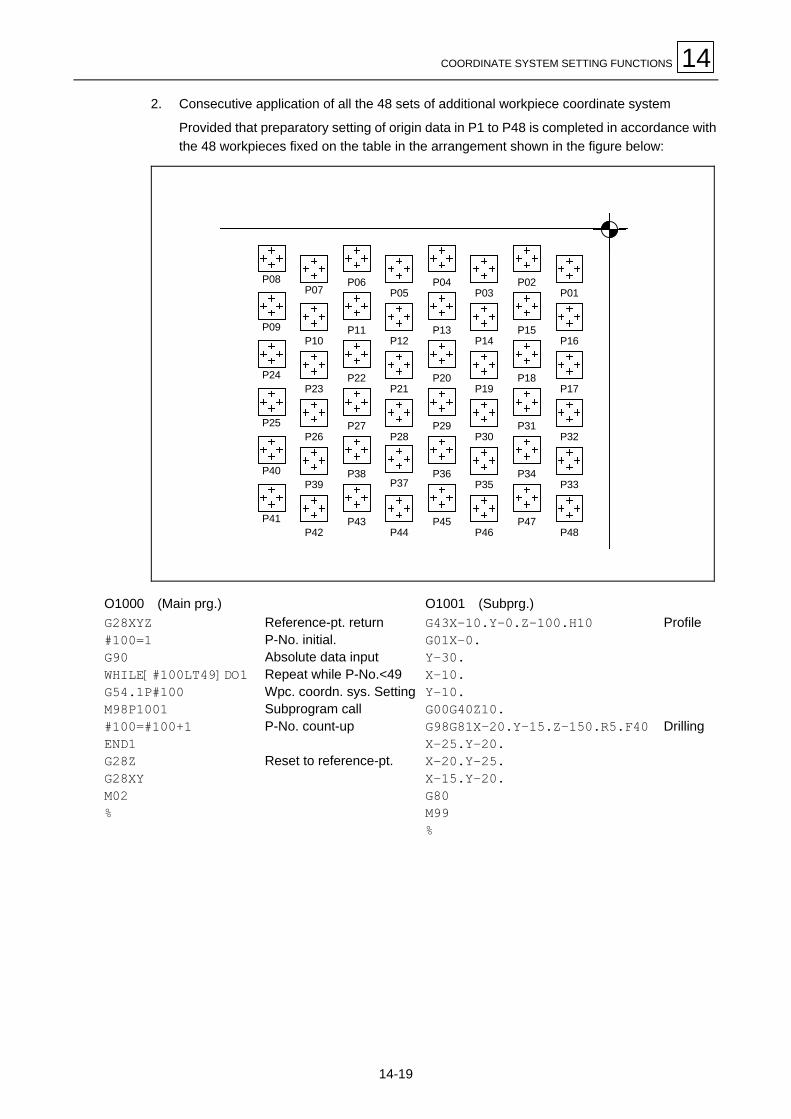
COORDINATE SYSTEM SETTING FUNCTIONS 14
14-19
2. Consecutive application of all the 48 sets of additional workpiece coordinate system
Provided that preparatory setting of origin data in P1 to P48 is completed in accordance withthe 48 workpieces fixed on the table in the arrangement shown in the figure below:
P08P07
P06P05
P04P03
P02P01
P09P10
P11P12
P13P14
P15P16
P24P23
P22P21
P20P19
P18P17
P25P26
P27P28
P29P30
P31P32
P40P39
P38P37
P36P35
P34P33
P41P42
P43 P45P46
P47P48P44
O1000 (Main prg.) O1001 (Subprg.)G28XYZ#100=1G90WHILE[#100LT49]DO1G54.1P#100M98P1001#100=#100+1END1G28ZG28XYM02%
Reference-pt. returnP-No. initial.Absolute data inputRepeat while P-No.<49Wpc. coordn. sys. SettingSubprogram callP-No. count-up
Reset to reference-pt.
G43X�10.Y�0.Z�100.H10G01X�0.Y�30.X�10.Y�10.G00G40Z10.G98G81X�20.Y�15.Z�150.R5.F40X�25.Y�20.X�20.Y�25.X�15.Y�20.G80M99%
Profile
Drilling

14 COORDINATE SYSTEM SETTING FUNCTIONS
14-20
3. Application of additional systems via transmission into G54 to G59
Provided that preparatory setting of origin data in P1 to P24 is completed in accordance withthe 24 sections of a workpiece fixed on the rotary table as shown in the figure below:
P20P19
P21P23
P22P24
P1P3
P2
P5
P4P6
ZY
X
B
O2000 (Main prg.) O2001 (Origin-data transference)G28 XYZBG90G00 B0G65 P2001A1M98 P2002G00 B90.G65 P2001A7M98 P2002G00 B180.G65 P2001A13M98 P2002G00 B270.G65 P2001A19M98 P2002G28 XYBM02%
Reference-pt. returnAbsolute data inputTable indexed f. 1. surf.Origin-data loadingDrilling-subprg. callTable indexed f. 2. surf.
Table indexed f. 3. surf.
Table indexed f. 4. surf.
Reset to reference-pt.
#2=5221#3=[#1�1]20+7001#5=0WHILE[#5LT6]DO1#6=#2#7=#3#4=0WHILE[#4LT6]DO2#[#6]=#[#7]#6=#6+1#7=#7+1#4=#4+1END2#2=#2+20#3=#3+20#5=#5+1END1M99%
Init.-var.-No. of 1. G-sys.Init.-var.-No. of 1. P-sys.Sys.-qty-counter clearedCheck f. sys.-qty.1.-ax.-var.-No. of receiver1.-ax.-var.-No. of transm.Axis-qty-counter clearedCheck f. axis-qty.Transmission of var.-dataAxis-qty count-up f. recvr.Axis-qty count-up f. transm.Axis-qty counter up
Init.-var.-No. of next G-sys.Init.-var.-No. of next P-sys.Sys.-qty-counter up
O2002 (Drilling subprg.)G54 M98 H100G55 M98 H100G56 M98 H100G57 M98 H100G58 M98 H100G59 M98 H100G28 Z0M99N100G98G81X�0.Y�15.Z�50.R5.F40X�25. Y�20.X�20. Y�25.X�15. Y�20.G80G28ZM99%
Drilling in G54-systemDrilling in G55-systemDrilling in G56-systemDrilling in G57-systemDrilling in G58-systemDrilling in G59-system
Fixed cycle for drilling

COORDINATE SYSTEM SETTING FUNCTIONS 14
14-21
4. Simplified version of Example 3 program in application of “G54.1 Pp”
Provided that preparatory setting of origin data in P1 to P24 is completed in accordance withthe 24 sections of a workpiece fixed on the rotary table as shown in the figure below:
P20P19
P21P23
P22P24
P1P3
P2
P5
P4P6
ZY
X
B
O3000G28 XYZBG90G00 B0G65 P3001A1G00 B90.G65 P3001A7G00 B180.G65 P3001A13G00 B270.G65 P3001A19G28 XYBM30%
Reference-point returnSelection of absolut data inputIndexing of table for 1st surface
Indexing of table for 2nd surface
Indexing of table for 3rd surface
Indexing of table for 4th surface
Reset to reference-point
O3001#100=#1#101=0WHILE[#101LT6]DO1G54.1P#100M98H100#100=#100+1#101=#101+1END1G28Z0M99N100G98G81X�20.Y�15.Z�150.R5.F40X�25. Y�20.X�20. Y�25.X�15. Y�20.G80G28ZM99%
Initialization of P-No.Initialization of counter
Setting of additional workpiece coordinate systemCall for drilling subroutineP-No. count-upChecking counter count-up
Fixed cycle for drilling

14 COORDINATE SYSTEM SETTING FUNCTIONS
14-22
14-11 Local Coordinate System Setting: G52
1. Function and purpose
A local coordinate system in which the designated position becomes the program origin can beset on the current workpiece coordinate system by setting command code G52.Command code G52 can also be used instead of G92 to update any positional shift between themachining program origin and the workpiece origin.
2. Programming format
G52 Xx1 Yy1 Zz1 αα1 (α: Additional axis)
3. Detailed description
Command G52, which causes no machine movement, is valid until a new G52 is issued.Command G52 is therefore convenient for using a new coordinate system without changing theorigin of the workpiece coordinate system.The local coordinate system offset data is cleared by execution of either an automaticreference-point return operation, or a manual reference-point (zero point) return operation usingthe watchdog method following power-on.
R
M
Ln
Ln
Ln
(G90)G52 X_ Y_
Incremental value(G91) G52X_ Y_
Reference point
Wn (n = 1 thru 6)
Absolute value
Workpiece coordinate system
Workpiece coordinate system offset(CRT setting, G10 G54 X_ Y_ )
External workpiece coordinate system setting(PC input, CRT setting)
Local coordinatesystems
Absolute value
Machine coordinate systemMEP215
Coordinates given in the absolute data input mode (G90) refer to the local coordinate system.

COORDINATE SYSTEM SETTING FUNCTIONS 14
14-23
4. Sample programs
1. Setting local coordinates in the absolute data input mode (local coordinate system offsetdata is not integrated)
[1] G28X0Y0[2] G00G90X1.Y1.[3] G92X0Y0[4] G00X500.Y500[5] G52X1.Y1.[6] G00X0Y0[7] G01X500.F100[8] Y500.[9] G52X0Y0[10] G00X0Y0
[10]
500 1000 1500 2000 2500 3000
500
1000
1500
2000
2500
[1]
[3][2]
[5][4]
[8][9]
[6]
[W1] L1
[W1]
X
Y
[7]
Local coordinate systemestablished by [5]
New coordinate system set by [3],which coincides with the local coordinatesystem set by [9]
Current positionR#1W1
MEP216
The local coordinate system is established by [5] and cancelled by [9], and coincides withthe coordinate system of [3].

14 COORDINATE SYSTEM SETTING FUNCTIONS
14-24
2. Setting local coordinates in the incremental data input mode (local coordinate system offsetdata is integrated)
[1] G28X0Y0 (a) O100[2] G92X0Y0 (b) G90G00X0Y0[3] G91G52X500.Y500. (c) G01X500.[4] M98P100 (d) Y500.[5] G52X1.Y1. (e) G91[6] M98P100 (f) M99[7] G52X�1.5Y�1.5[8] G00G90X0Y0
M02
500 1000 1500 2000 2500 3000
500
1000
1500
2000
2500
[1]
[3][2]
[4]
[8]
[W1] L1
X
Y
[8]
[W1] L2(c)
(d)
[6]X’’
X’
Y’’Y’
(d)
(c)
(b)
R#1W1
Local coordinate systemestablished by [5]
New coordinate system set by [3]
Coincides with the local coordinatesystem set by [7]
Current
MEP217
Block [3] generates local coordinate system X’-Y’ at the position of (500, 500) in the X-Ycoordinate system.Block [5] generates local coordinate system X”-Y” at the position of (1000, 1000) in the X’-Y’coordinate system.Block [7] generates a local coordinate system at the position (–1500, –1500) in the X”-Y”coordinate system. That is, the local coordinate system and the X-Y coordinate systemcoincide, which means that the former has been cancelled.
…

COORDINATE SYSTEM SETTING FUNCTIONS 14
14-25
3. Combined use of local coordinate system and workpiece coordinate system[1] G28X0Y0 (a) O200[2] G00G90G54X0Y0 (b) G00X0Y0[3] G52X500.Y500. (c) G01X500.F100[4] M98P200 (d) Y500.[5] G00G90G55X0Y0 (e) M99[6] M98P200 %[7] G00G90G54X0Y0
M02
500 1000 1500 2000 2500 3000
500
1000
1500
2000
2500
[1]
W1
R#1X
Y
3000
Local coordinate systemestablished by [3]
Workpiece origin data
Current
[W1] L1
W2(c)
[3][2]
[7]
[5]
G54
G55
G54
1000500
G55
10002000
XY
(d)
(b)
(b)
(d)
(c)
MEP218
Block [3] generates a local coordinate system at the position of (500, 500) in the G54coordinate system no local coordinate system is generated in the G55 coordinate system.
Block [7] performs a movement to the local coordinate system reference point (zero point) ofG54.
The local coordinate system can be cancelled using this format:
G90 G54 G52 X0 Y0
…

14 COORDINATE SYSTEM SETTING FUNCTIONS
14-26
4. Combined use of G54 workpiece coordinate system and multiple local coordinate systems[1] G28X0Y0 (a) O300[2] G00G90G54X0Y0 (b) G00X0Y0[3] M98P300 (c) G01X500.F100[4] G52X1.Y1. (d) Y500.[5] M98P300 (e) X0Y0[6] G52X2.Y2. (f) M99[7] M98P300 %[8] G52X0Y0 M
M02
[3]
[5]
500 1000 1500 2000 2500 3000
500
1000
1500
2000
2500
[1]W1
R#1
3000
[8][2]
G54
(d)
[W1] L1
[W1] L2
[7]
(c)(e)
(b)
Local coordinate systemestablished by [6]
G54
500500
XY Workpiece origin data
Local coordinate systemestablished by [4]
Current position
MEP219
Block [4] generates a local coordinate system at the position of (1000, 1000) in the G54coordinate system.Block [6] generates a local coordinate system at the position of (2000, 2000) in the G54coordinate system.Block [8] makes the local coordinate system coincide with the G54 coordinate system.

COORDINATE SYSTEM SETTING FUNCTIONS 14
14-27
14-12 Reading/Writing of MAZATROL Program Basic Coordinates
The basic coordinates of a MAZATROL program can be read or rewritten by calling a usermacroprogram in the subprogram unit of the MAZATROL program.
UNo. UNIT X 1 WPC-0 �100.
UNo. UNIT . . . . 5 SUB PRO . . . . . .
M3P378
G65P9998X ..........M99
Main program(MAZATROL)
Macroprogram(EIA/ISO)
The WPC coordinates of line UNo. 1 can beread or rewritten.
Note 1: For updating the basic coordinates, do not forget to select the [MEASURE MACRO]menu function in entering a subprogram unit for the macroprogram concerned (WNo.9998); otherwise the new coordinates may not always be used in time for the executionof the machining unit immediately following the subprogram unit.
Note 2: On the other hand, do not select the [MEASURE MACRO] menu function unless theabove macroprogram is to be used.
14-12-1 Calling a macroprogram (for data writing)
To rewrite the basic coordinates data, call the specific user macroprogram from a subprogramunit of the MAZATROL program (macroprogram call is not required for data reading).Refer to the section of subprogram unit in the Programming Manual (MAZATROL Programming)for details on data setting for subprogram call.
14-12-2 Data reading
System variables can be used to read the MAZATROL basic coordinates that are effective duringmacroprogram execution.
System variables for MAZATROL basic coordinates (WPC)
Variables number Function Variables number Function
#5341 WPC-X #5344 WPC-4
#5342 WPC-Y #5345 WPC-5
#5343 WPC-Z #5347 WPC-th

14 COORDINATE SYSTEM SETTING FUNCTIONS
14-28
14-12-3 Rewriting
Same as reading, you are to use system variables when rewriting the basic coordinates.
The basic coordinates, however, cannot be rewritten just by entering the data into #5341 through#5347. It is therefore necessary to create a macroprogram in the following format:
1. Macroprogramming format
G65 P9998 X_Y_Z_D_B_C_
M99
- At the end of macroprogramming, call the rewriting macroprogram (WNo. 9998). At this time,assign new coordinates as arguments. The relationship between each argument and axis is asfollows:
X: WPC-X Y: WPC-Y Z: WPC-Z
D: WPC-th B: WPC-4 C: WPC-5
- Only the coordinates assigned with the respective argument are rewritten. The argument datais handled as data having the decimal point.
2. Rewriting macroprogram
The rewriting macroprogram (WNo. 9998) is shown below.
O9998 N30 #50467=#50467OR�65536IF[#50600EQ0]GOTO60 IF[#7EQ#0]GOTO40 #50499=#50499OR1IF[#24EQ#0]GOTO10 #5347=#7 N60#5341=#24 #50441=#7 M99#50449=#24 #50467=#50467OR512 %#50467=#50467OR32 N40N10 IF[#2EQ#0]GOTO45IF[#25EQ#0]GOTO20 #5344=#2#5342=#25 #50443=#2#50447=#25 #50467=#50467OR256#50467=#50467OR64 N45N20 IF[#3EQ#0]GOTO50IF[#26EQ#0]GOTO30 #5345=#3#5343=#26 #50453=#3#50445=#26 #50467=#50467OR1024#50467=#50467OR128 N50
Note: An alarm will occur when executing the macroprogram if no basic coordinates ofMAZATROL program are currently validated.
The body of the macroprogramto be created by the user

COORDINATE SYSTEM SETTING FUNCTIONS 14
14-29
14-13 Workpiece Coordinate System Rotation
1. Function and purpose
The function refers to rotating the workpiece coordinate system around the position of thespecified machine coordinates. The machining program can be rotated in its entirety as requiredfor the actual inclination of the workpiece.
2. Programming format
(G17) G92.5 Xx Yy Rr X-Y plane(G18) G92.5 Zz Xx Rr Z-X plane(G19) G92.5 Yy Zz Rr Y-Z planeor(G17) G92.5 Xx Yy Ii Jj X-Y plane(G18) G92.5 Zz Xx Kk Ii Z-X plane(G19) G92.5 Yy Zz Jj Kk Y-Z plane
x, y, z : Coordinates of the rotational center.The position along the two axes of the previously selected X-Y, Z-X, or Y-Z plane must be designatedin machine coordinates.The designation for an axis not corresponding to the plane will be ignored.
R : Angle of rotation.Designate the rotational angle for the coordinate system. A positive value refers to a counterclockwiserotation.
i, j, k : Axial component vectors.The angle for coordinate system rotation can also be designated in axial component vectorscorresponding to the previously selected plane.The designation for an axis not corresponding to the plane will be ignored.
x
yjr
i
X
r
Rotationalcenter
Machine origin
Machinecoordinate
Workpiececoordinate system
Workpiece coordinate system rotation
Y
Range and unit for angle data setting
Setting method Setting range Setting unit
Metric system 0 to ±99999.999 0.001 mmAxial component vectors(i, j, k) Inch system 0 to ±9999.9999 0.0001 in.
Metric systemAngle of rotation ( r )
Inch system0 to ±99999.999° 0.001°

14 COORDINATE SYSTEM SETTING FUNCTIONS
14-30
3. Detailed description
1. Irrespective of the actual mode for incremental or absolute data input, the values ataddesses X, Y, Z, or I, J, K as well as R are always referred to the machine coordinatesystem.
2. Two methods are available to designate a rotational angle:(a) Designation in rotational angle (r), or(b) Designation in axial component vectors (i, j, k).
3. If angle data are entered using both methods (a) and (b) above, the rotational angle (ataddress R) will govern.
4. If, during rotation of the workpiece coordinate system, a rotational angle of zero degrees isdesignated (by setting G92.5 R0, for example), the coordinate system rotation will becancelled, irrespective of the data input mode of G90 (absolute) or G91 (incremental). Thenext move command will then be executed for the ending point in the original (not rotated)workpiece coordinate system (refer to Article 1 in Item 5. Precautions).
5. The rotational center coordinates will be retained and automatically applied for asucceeding rotation command without data designation at addresses X, Y, and/or Z.
Example: N1 G17 Selection of the X-Y planeN2 G92.5X100.Y100.R45.M
Rotation of the workpiece coordinate system through45 deg around the point of (X, Y) = (100, 100)
N3 G92.5R0M
Cancellation of the workpiece coordinate systemrotation
N4 G17G92.5R90.M%
Rotation of the workpiece coordinate system through90 deg around the center last programmed (X100,Y100)
6. Omission of addresses R and I, J , K is regarded as a rotational angle designation of zerodegrees.
Example: “G92.5 X0. Y0.” is equivalent to “G92.5 X0. Y0. R0”.
7. Alarm No. 809 ILLEGAL NUMBER INPUT will be displayed if the specified axial componentvectors (i, j, k) or rotational angle (r) oversteps the effective setting range.
8. Plane selection (by codes G17, G18, and G19) need not be included in the block of G92.5, ifthe rotation shall be performed on the currently active plane.
9. The designation for an axis not corresponding to the selected plane will be ignored. Thedesignations at addresses Z and K in a block of G92.5, for example, will be ignored in themode of G17 (X-Y plane).
Example: The second block shown below rotates the workpiece coordinate system through63.435 , calculation from tan–1(2/1), around the point of (X, Y) = (10, 20) on the X-Yplane, and the values at Z and K are ignored for the rotation.G17G92.5X10.Y20.Z30.I1.J2.K3.
Even the ignored axial values at X, Y, and Z in a G92.5 block are retained as well asthe values actually used (see Article 5 above) and, for example, if the G92.5 blockshown above is followed byG19G92.5J2.K3.
then the workpiece coordinate system will be rotated around the point of (Y, Z) = (20,30) through 56.301°, calculation from tan–1(3/2), on the Y-Z plane (G19).

COORDINATE SYSTEM SETTING FUNCTIONS 14
14-31
4. Examples of operation
1. Rotation around the machine origin.
N1 G28X0Y0N2 G17N3 G90N4 G55N5 G92.5X0Y0R90. .................................
(or G92.5X0Y0I0J1.)N6 G0X0Y0N7 G1X100.F1000.N8 Y200.N9 X0.N10 Y0.N11 M30%
Rotation around the machine originthrough 90 deg
100 200 300X
–100–200–300
100
200
300
Y
W2Y X
YX
N8
N9
N10
N7
W2'
N6
RM
0
90°
Workpiece originafter rotation
Workpiece originwithout rotation
Programmed contour afterworkpiece coordinatesystem rotation
Programmed contourwithout workpiececoordinate systemrotation
Workpiece coordinates systems
Machine coordinate system
- The block of G92.5 under N5 rotates the workpiece coordinate system through 90 degreesaround the origin of the machine coordinate system. For N6 onward, the machine operatesaccording to the rotated workpiece coordinate system.
- The above example of the vector setting method for the same 90-deg rotation is based on thefollowing calculation:
θ = tan–1 (J/I) = tan–1 (1/0) = 90°.
G55 (Work Offset)X100.Y100.

14 COORDINATE SYSTEM SETTING FUNCTIONS
14-32
2. Rotation around the workpiece origin.
N1 G28X0Y0Z0N2 G17N3 G55N4 G90N5 G92.5X100.Y100.R45......................N6 G81X50.Y50.Z�25.R�5.F500N7 X100.N8 X150.N9 M30%
Rotation through 45 deg around the point ofmachine coordinates X=100 and Y=100 (thatis, the origin of the G55 workpiece coordinatesystem).
100 200 300
100
200
300
RM
W2W2’
45°
X
Y
Holemachining
Workpiececoordinatessystems
Programmed contour withoutworkpiece coordinate systemrotation
Workpiece coordinatesystem after rotation
Programmed contour afterworkpiece coordinatesystem rotation
Workpiece coordinate systemwithout rotation
- The block of G92.5 under N5 rotates the workpiece coordinate system around its own originthrough 45 degrees. For N6 onward, the machine operates according to the rotated workpiececoordinate system.
- Set the rotational center on the workpiece origin, as shown in this example, to rotate the currentworkpiece coordinate system around its own origin.
G55 (Work Offset)X100.Y100.

COORDINATE SYSTEM SETTING FUNCTIONS 14
14-33
3. Programmed coordinate rotation (G68) in the mode of G92.5
N1 G28X0Y0N2 G17N3 G55N4 G90N5 G92.5X0Y0R90. ...............................N6 G68X50.Y50.R45. ...........................N7 G0X0Y0N8 G1X100.F500N9 Y100.N10 X0N11 Y0N12 M30%
[1][2]
100 200–100–200
100
200
R M
N9 N8
N10 N11W2’ W2N7
X
Y
Programmed contourwithout [2]
Programmed contourwithout both [1] and [2]
G68rot. ctr.
G68rot. ctr.
Programmed contourwith both [1] and [2] Programmed
contourwithout [1]
In a combined use with G92.5, the center of programmed coordinate rotation by G68 will be aposition which corresponds with the workpiece coordinate system rotation designated by theG92.5 command.It will not affect operation even if the order of the program blocks marked [1] and [2] above isreversed.
G55 (Work Offset)X100.Y100.

14 COORDINATE SYSTEM SETTING FUNCTIONS
14-34
4. Figure rotation (M98) in the mode of G92.5
N1 G28X0Y0N2 G17N3 G55N4 G90N5 G92.5X0Y0R90. ..........................N6 G0X0Y0N7 M98H10I�50.J50.L4N8 M30N9N10 G1X100.Y50.F500N11 X0Y100.N12 M99%
Rotation through 90 deg around the origin of themachine coordinate system
100 200–100–200
100
200
R M–300
300
N11(1)
N10(1)
N10(2)
N11(2)
N10(3) N11(3)
N10(4)
N11(4)
W2’
W2
N6
Fig. rot. ctr.
Fig. rot. ctr.
Programmed contour withoutworkpiece coordinate system rotation
Programmed contour afterworkpiece coordinate
system rotation
Serialnumber ofrepetition
X
Y
In a combined use with G92.5, the center of figure rotation by M98 will be a position whichcorresponds with the workpiece coordinate system rotation designated by the G92.5 command.
G55 (Work Offset)X100.Y100.
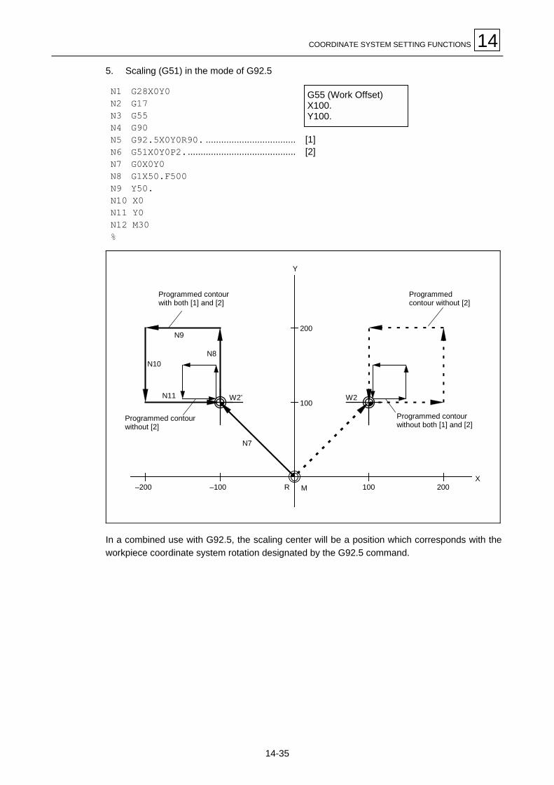
COORDINATE SYSTEM SETTING FUNCTIONS 14
14-35
5. Scaling (G51) in the mode of G92.5
N1 G28X0Y0N2 G17N3 G55N4 G90N5 G92.5X0Y0R90. ...................................N6 G51X0Y0P2...........................................N7 G0X0Y0N8 G1X50.F500N9 Y50.N10 X0N11 Y0N12 M30%
[1][2]
100 200–100–200
100
200
R M
W2’ W2
N7
N9
N10
N11
N8
X
Y
Programmed contourwith both [1] and [2]
Programmed contourwithout [2]
Programmedcontour without [2]
Programmed contourwithout both [1] and [2]
In a combined use with G92.5, the scaling center will be a position which corresponds with theworkpiece coordinate system rotation designated by the G92.5 command.
G55 (Work Offset)X100.Y100.

14 COORDINATE SYSTEM SETTING FUNCTIONS
14-36
6. Mirror image in the mode of G92.5
a) G-code mirror image
N1 G28X0Y0N2 G17N3 G55N4 G90N5 G92.5X0Y0R90. ..............................N6 G51.1X�50......................................N7 G0X0Y0N8 G1X100.F500N9 Y100.N10 X0Y0N11 M30%
[1][2]
100 200–100–200
100
200
R
N8
M
–100
X
Y
N10
N9
W2’
W2
N7
Mirror axis (Without G92.5)
Programmedcontour without [1]
Mirror axis(Without G92.5)
Programmed contourwithout both [1] and [2]
Programmedcontour without [2]
Programmed contourwith both [1] and [2]
G55 (Work Offset)X100.Y100.

COORDINATE SYSTEM SETTING FUNCTIONS 14
14-37
b) M-code mirror image
N1 G28X0Y0N2 G17N3 G55N4 G90N5 G92.5X0Y0R90. ..................................N6 M91. ..........................................................N7 G0X0Y0N8 G1X100.F500N9 Y100.N10 X0Y0N11 M30%
[1][2]
100 200–100–200
100
200
R MX
Y
W2’ W2
N8
N9
N10 N7
Programmedcontour without [2]
Programmed contourwithout both [1] and [2]
Mirror axis(Without G92.5)
Programmed contourwith both [1] and [2]
Mirror axis (With G92.5)
Programmedcontour
without [1]
In a combined use with G92.5, the axis of symmetry for G-code or M-code mirror image will beset in accordance with the workpiece coordinate system rotation designated by the G92.5command.
G55 (Work Offset)X100.Y100.

14 COORDINATE SYSTEM SETTING FUNCTIONS
14-38
7. Coordinate system setting (G92) in the mode of G92.5
N1 G28X0Y0N2 G17N3 G55N4 G90N5 G92.5X0Y0R90. ..............................N6 G92X�100.Y100. ............................N7 G0X0Y0N8 G1X100.F500N9 Y100.N10 X0Y0N11 M30%
[1][2]
100
200
–100–200
100
200
MR
X
Y
W2
N9
N10N8
–100
N7
W2’
Programmedcontour without [2]
Programmed contourwith both [1] and [2]
Programmed contourwithout both [1] and [2]
Programmed contour without [1]
Coordinate system setting by a G92 block after G92.5 will be performed in reference to thecoordinate system rotation designated by the G92.5 command.
G55 (Work Offset)X100.Y100.

COORDINATE SYSTEM SETTING FUNCTIONS 14
14-39
5. Precautions
1. If, during rotation of the workpiece coordinate system, a rotational angle of zero degrees isdesignated (by setting G92.5 R0, for example), the coordinate system rotation will becancelled, irrespective of the data input mode of G90 (absolute) or G91 (incremental). Thenext move command will then be executed for the ending point in the original (not rotated)workpiece coordinate system.
Example 1: For incremental data input
N1 G28X0Y0N2 G17G92.5X0Y0R20.N3 G91G01Y50.F1000.N4 X100.N5 G92.5R0 ........................................N6 Y�50. ............................................N7 X�100.N8 M30%
Command for 0-deg rotationMotion to (X100, Y0)
Example 2: For absolute data input
N1 G28X0Y0N2 G17G92.5X0Y0R20.N3 G90G01Y50.F1000.N4 X100.N5 G92.5R0 ........................................N6 Y0 ...................................................N7 X0N8 M30%
Command for 0-deg rotationMotion to (X100, Y0)
Programmed contour for Examples 1 and 2 above
N4
0 100
50
N3
N7
N6
X
Y Programmed contour with N2(Workpiece coordinate system rotation)
Programmed contourwithout N2

14 COORDINATE SYSTEM SETTING FUNCTIONS
14-40
2. Use a linear motion command (with G00 or G01) for the first movement to be executed afterG92.5 command.Circular interpolation in such a case, as shown below, would have to take place from thecurrent position A, which refers to the original workpiece coordinate system, to the endingpoint B’ to which the point B should be shifted in accordance with the rotation. As a result,the radii of the starting and ending points would differ too significantly and the alarm No. 817INCORRECT ARC DATA would be caused.
Example:
N1 G28X0Y0N2 G91G01X50.F1000.N3 G17G92.5X0Y0R20.N4 G02X40.Y40.I40.N5 M30%
Circular interpolation as the first motion after G92.5
Center of arc
Programmed contourwithout N3
Alarm for incorrectcircular commandB'
Rs : Arc radius for the starting pointRe : Arc radius for the ending point
40
0
Programmed contourwithout N2
50 90
20°
B
Re
RsA
3. Set a G92.5 command in the mode of G40.
4. The machine will operate on the rotated coordinate system for an MDI interruption duringthe mode of G92.5.
5. For a manual interruption during the mode of G92.5 using the JOG or handle feed mode,the machine will operate independently of the coordinate system rotation.

COORDINATE SYSTEM SETTING FUNCTIONS 14
14-41
6. Differences between workpiece coordinate system rotation and programmed coordinaterotation.
Function name Workpiece coordinate system rotation Programmed coordinate rotation
System to be rotated Workpiece coordinate system Local coordinate system
Programming format (G17) G92.5 Xx Yy Rr
(G18) G92.5 Yy Zz Rr (Angle)
(G19) G92.5 Zz Xx Rr
or
(G17) G92.5 Xx Yy Ii Jj
(G18) G92.5 Yy Zz Jj Kk (Vector comp.)
(G19) G92.5 Zz Xx Kk Ii
(G17) G68 Xx Yy Rr
(G18) G68 Yy Zz Rr
(G19) G68 Zz Xx Rr
Operation
Rotationalt
y
i
jr
x
r
Workpiececoordinate system
Local coordinatesystem
Workpiececoordinate system
Machine coordinate system
r
Rotational center coordinates Designation at addresses X, Y, Z Designation at addresses X, Y, Z
Angle of rotation Designation at R (angle) or at I, J, K (vectorcomponents)
Designation at R (angle)
Power-off → on Retained Cleared
M02/M30 Retained Cleared
Reset key Retained Cleared
Informationon centerand angle ofrotationcleared? Resumption of
readiness afteremergencystop
Retained Cleared
Note: Resetting or M02/M30 cancels the G92.5 mode itself, while the information on therotational center, etc., at related addresses is retained as indicated above.
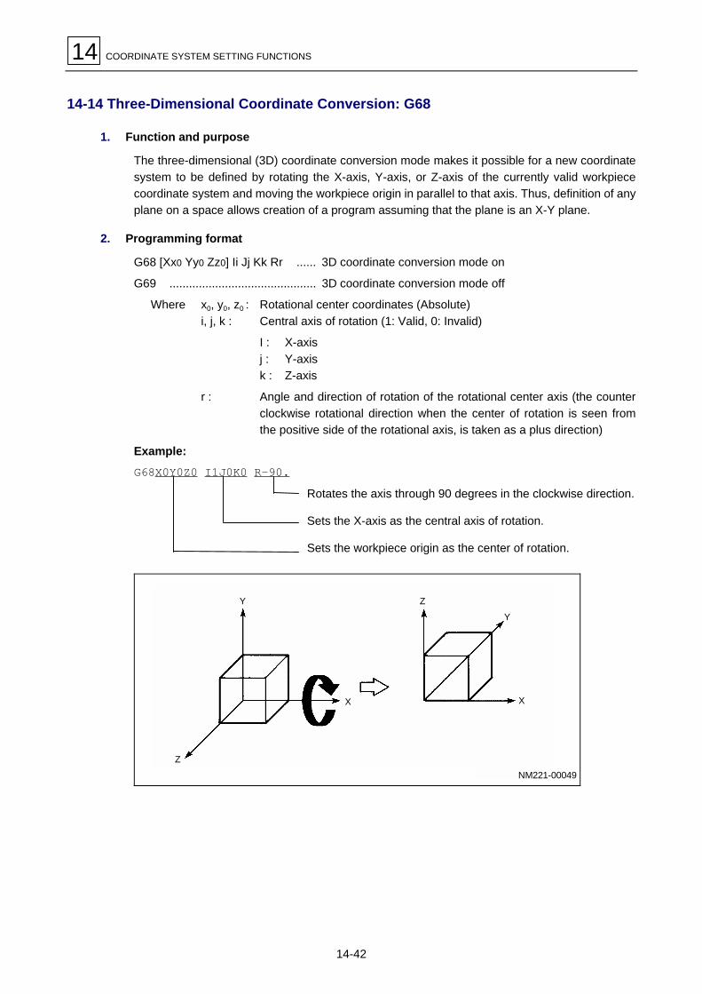
14 COORDINATE SYSTEM SETTING FUNCTIONS
14-42
14-14 Three-Dimensional Coordinate Conversion: G68
1. Function and purpose
The three-dimensional (3D) coordinate conversion mode makes it possible for a new coordinatesystem to be defined by rotating the X-axis, Y-axis, or Z-axis of the currently valid workpiececoordinate system and moving the workpiece origin in parallel to that axis. Thus, definition of anyplane on a space allows creation of a program assuming that the plane is an X-Y plane.
2. Programming format
G68 [Xx0 Yy0 Zz0] Ii Jj Kk Rr ...... 3D coordinate conversion mode on
G69 ............................................. 3D coordinate conversion mode off
Where x0, y0, z0 : Rotational center coordinates (Absolute)i, j, k : Central axis of rotation (1: Valid, 0: Invalid)
I : X-axisj : Y-axisk : Z-axis
r : Angle and direction of rotation of the rotational center axis (the counterclockwise rotational direction when the center of rotation is seen fromthe positive side of the rotational axis, is taken as a plus direction)
Example:
G68X0Y0Z0 I1J0K0 R�90.Rotates the axis through 90 degrees in the clockwise direction.
Sets the X-axis as the central axis of rotation.
Sets the workpiece origin as the center of rotation.
NM221-00049
Y
Z
Z
Y
X X

COORDINATE SYSTEM SETTING FUNCTIONS 14
14-43
<Precautions>
- If X, Y, or Z is omitted, the workpiece origin in the currently valid workpiece coordinate systemwill become rotational center coordinates.
- The charatcters I, J, and K must all be set. Omission of even one of these three charactersresults in alarm 807 ILLEGAL FORMAT. Omission of all the three characters makes programcoordinate rotation valid, instead of 3D coorinate conversion.
G68X0Y0Z0I1K0R�45. Format error
G68X0Y0Z0R�45. Program coordinate rotation ON
- Setting of 0 in all the arguments of I, J, and K also results in alarm 807 ILLEGAL FORMAT.
- Setting of 1 in the arguments of two or more of the three characters (I, J, and K) also results inalarm 807 ILLEGEAL FORMAT.
G68X0Y0Z0I1J1K0R�90. Format error
- Setting of command G68 in the absence of a 3D coordinate conversion option results in alarm942 NO 3-D CONVERSION OPTION.
- Setting of an illegal G-code during the 3D coordinate conversion mode results in alarm 943CONVERTING IN 3-D CORDINATES.See Paragraph 5. Relationship to other functions, for the listing of illegal G-codes.
3. Sample program
N01 G90G00G40G49G80G54X0Y-100. """"""""" [1]G43Z50.H01 """"""""" [2]G01Z-1.F1200 """"""""" [3]Y-50. """"""""" [4]G02X100.R50. """"""""" [5]G01Y-100. """"""""" [6]G01Z50. """"""""" [7]G91G28Z0 """"""""" [8]G28X0Y0 """"""""" [9]
N02 G90G00G40G49G80G54G00A90.
G68I1J0K0R-90.G00X0Y0 """"""""" [10]G43Z50.H01 """"""""" [11]G01Z-1. """"""""" [12]Y50. """"""""" [13]G02X100.R50. """"""""" [14]G01Y0 """"""""" [15]G01Z50. """"""""" [16]G69G91G28Z0 """"""""" [17]G28X0Y0 """"""""" [18]M30
X
Y
Z[1]
[2][3]
[4]
[5]
[6]
[7][8]
[16][17][13]
[12]
[11] [10]
[18]
[14]
[15]
[9] Z
X
Y
Program origin
Machine origin
Machine origin
Programorigin
NM221-00050

14 COORDINATE SYSTEM SETTING FUNCTIONS
14-44
4. 3D coordinate conversion and a program coordinate system
Use of command G68 allows the coordinates of the rotational center in the currently validcoordinate system to be shifted to the designated position (X, Y, Z) and the correspondinggraphics to be rotated through the designated angle of rotation (R) in the designated direction ofrotational center (I, J, K). Thus, a new program coordinate system can be set.
Example: [1] G90 G54 X0 Y0[2] G68 X10.Y0 Z0 I0 J1 K0 R-30.[3] G68 X0 Y10.Z0 I1 J0 K0 R45.[4] G69
[1] Set a workpiece coordinate system using workpiece offset command G54.
[2] The program origin in the workpiece coordinate system that was set during step [1]above shifts to the position of (x, y, z) =(10, 0, 0) and the graphics rotates through 30degrees in a clockwise direction around the Y-axis. Thus, new program coordinatesystem A is set.
[3] The program origin in the workpiece coordinate system that was set during step [2]above shifts to the position of (x, y, z) = (0, 10, 0) and the graphics rotates through 45degrees in a counter clockwise direction around the X-axis. Thus, new programcoordinate system B is set.
[4] Both the program coordinate systems that were set during steps [2] and [3] above arecancelled and the coordinate system that was set during step [1] above becomes validonce again.
+Z
P (0, 0, 0)
P’ (10, 0, 0)+X
+Y’
+Z’
+X’
+X”
P (0, 10, 0)
45°
NM221-00051
–30°
+Y
+Y”Program coodinate system B
Workpiece coodinate system
Program coodinate system A

COORDINATE SYSTEM SETTING FUNCTIONS 14
14-45
5. Relationship to other functions
1. The table below indicates the compatibility of each G-code with the 3D coordinateconversion function in the two columns on the right.
[1] Is the G-code available in the mode of 3D coordinate conversion?[2] Is the 3D coordinate conversion mode selectable under the condition of the G-code?
G-code Group Function [1] [2]
00 01 Positioning Yes Yes
01 01 Linear interpolation Yes Yes
01.1 01 Threading with C-axis Yes No
02 01 Circular interpolation CW Yes (*1) No
03 01 Circular interpolation CCW Yes (*1) No
02.1 00 Spiral interpolation CW No No
03.1 00 Spiral interpolation CCW No No
04 00 Dwell Yes (*4)
05 00 High-speed machining No No
06.1 01 Spline interpolation No No
06.2 01 NURBS interpolation No No
07 00 Virtual-axis interpolation No No
07.1 00 Cylindrical interpolation Yes No
09 00 Exact-stop check Yes
10 00 Programmed parameter input Yes (*4) No
11 00 Programmed parameter input cancel Yes (*4)
17 02 Plane selection X-Y Yes Yes
18 02 Plane selection Z-X Yes Yes
19 02 Plane selection Y-Z Yes Yes
20 06 Inch command No Yes
21 06 Metric command No Yes
22 04 Pre-move stroke check ON No No
23 04 Pre-move stroke check OFF No Yes
27 00 Reference-point check No
28 00 Reference-point return Yes (*2)
29 00 Starting-point return Yes
30 00 No. 2 through 4 reference-point return Yes (*2)
31 00 Skip Yes
31.1 00 Multi-step skip 1 Yes
31.2 00 Multi-step skip 2 Yes
31.3 00 Multi-step skip 3 Yes
32 01 Constant lead threading No No
33 01 Constant lead threading No No
34 01 Variable lead threading No No
37 00 Automatic tool-length measurement No
38 00 Tool-diameter offset vector selection No No
39 00 Tool-diameter offset corner arc No No
40 07 Tool-diameter offset cancel Yes Yes
40.1 15 Shaping cancel Yes No
41 07 Tool-diameter offset left Yes No
41.1 15 Shapint to the left Yes No
42 07 Tool-diameter offset right Yes No
42.1 15 Shaping to the right Yes No

14 COORDINATE SYSTEM SETTING FUNCTIONS
14-46
G-code Group Function [1] [2]
43 08 Tool-length offset (+) Yes No
44 08 Tool-length offset (–) Yes No
45 00 Tool-position offset, extension Yes No
45.1 19 Attachment compensation Yes Yes
46 00 Tool-position offset, reduction Yes No
47 00 Tool-position offset, double extension Yes No
48 00 Tool-positon offset, double reduction Yes No
49 08 Tool-length offset cancel Yes Yes
49.1 19 Attachment compensation cancel Yes Yes
50 11 Scaling cancel No Yes
51 11 Scaling on No No
50.1 19 G-command mirror image cancel Yes Yes
50.2 23 Polygonal machining cancel Yes Yes
51.1 19 G-command mirror image on Yes No
51.2 23 Polygonal machining Yes Yes
52 00 Local coordinate system setting Yes Yes
53 00 Machine coordinate system selection Yes (*5)
54 12 Workpiece coordinate system 1 selection No Yes
54.1 12 Additional workpiece coordinate system selection No Yes
55 12 Workpiece coordinate system 2 selection No Yes
56 12 Workpiece coordinate system 3 selection No Yes
57 12 Workpiece coordinate system 4 selection No Yes
58 12 Workpiece coordinate system 5 selection No Yes
59 12 Workpiece coordinate system 6 selection No Yes
60 00 One-way positioning Yes
61 13 Exact-stop check mode Yes Yes
61.1 13 Geometry compensation mode Yes Yes
61.4 13 Inverse model control Yes Yes
62 13 Automatic corner override Yes Yes
63 13 Tapping mode Yes Yes
64 13 Cutting mode Yes Yes
65 00 User macro simple call Yes
66 14 User macro modal call A Yes No
66.1 14 User macro modal call B Yes No
67 14 User macro modal call cancel Yes Yes
Program coordinates rotation No No68 16
3D coordinate conversion Yes Yes
69 16 Cancellation of coordinates rotation/3D conversion Yes (*2) Yes
71.1 09 Fixed cycle (chamfering cutter 1) Yes No
72.1 09 Fixed cycle (chamfering cutter 2) Yes No
73 09 Fixed cycle (high-speed deep-hole drilling) Yes No
74 09 Fixed cycle (reverse tapping) Yes No
75 09 Fixed cycle (boring) Yes No
76 09 Fixed cycle (boring) Yes No
77 09 Fixed cycle (back facing) Yes No
78 09 Fixed cycle (boring) Yes No
79 09 Fixed cycle (boring) Yes No
80 09 Fixed cycle cancel Yes Yes
81 09 Fixed cycle (drill/spot drill) Yes No
82 09 Fixed cycle (drill) Yes No

COORDINATE SYSTEM SETTING FUNCTIONS 14
14-47
G-code Group Function [1] [2]
82.2 09 Fixed cycle (drill) Yes No
83 09 Fixed cycle (deep hole drill) Yes No
84 09 Fixed cycle (tapping) Yes No
84.2 09 Fixed cycle (synchronous tapping) Yes No
84.3 09 Fixed cycle (synchronous reverse tapping) Yes No
85 09 Fixed cycle (reaming) Yes No
86 09 Fixed cycle (boring) Yes No
87 09 Fixed cycle (back boring) Yes No
88 09 Fixed cycle (boring) Yes No
89 09 Fixed cycle (boring) Yes No
90 03 Absolute data input Yes Yes
91 03 Incremental data input Yes Yes
92 00 Machine coordinate system setting No
92.5 00 Workpiece coordinate system rotation Yes
93 05 Inverse time feed Yes Yes
94 05 Asynchronous feed (feed per minute) Yes (*4) Yes
95 05 Synchronous feed (feed per revolution) Yes (*4) Yes
98 10 Initial level return in fixed cycle Yes Yes
99 10 R-point level return in fixed cycle Yes Yes
*1: Setting of helical interpolation results in an alarm.*2: Only the intermediate point has its coordinates converted.*3: Setting of program coordinate rotation results in an alarm.*4: The preparatory function is executed independently of the coordinate conversion.*5: The operation is always performed in the original coordinate system (free from any conversion).
2. Setting of a G-code other than G17, G18, and G19, in the block containing G68 or G69results in alarm 807 ILLEGAL FORMAT.
3. G28 and G30 commands permit a return to the reference point through the 3D convertedintermediate point, whereas a G53 command is performed without any conversion.
4. Codes G41 (Tool diameter offset left), G42 (Tool diameter offset right), G51.1 (G-commandmirror image on), and Fixed cycle codes must be present with their cancellation codesbetween G68 and G69 so that a nested relationship is established. Moreover, give a motioncommand with G90 (absolute data input) in the next block to that of the G68 command.
Example: G68X50.Y100.Z150.I1J0K0R-90.G90G00X0Y0Z0G41G01X10.F1000
M
M
G40G69
5. Tool-length, -diameter and -position offset is first processed, and the 3D conversion isconducted on the offset contour.
6. Mirror image can only be applied by G51.1 (the related M-codes are not available). Theprocessing order is: mirror image first, then 3D conversion.

14 COORDINATE SYSTEM SETTING FUNCTIONS
14-48
7. In mode G68, code G52 is handled as follows:
- If code G68 is set in the coordinates that have been set using G52, that local coordinatesystem will be overriden with a new workpiece coordinate system by G68. Setting of G69under that status will make the original local coordinate system valid once again.
G68
M: Machine coordinate systemW: Workpiece coordinate systemL: Local coordinate system
L
W
M
G69L
W
M
NM221-00052
- If code G52 is present in the data set using mode G68, a local coordinate system can beset on the workpiece coordinate system that has been set using G68. Setting of G69under that status will cancel the local coordinate system and the G68-set workpiececoordinate system and thus the original coordinate system existing before G68 was setwill become valid once again.
G68L
M: Machine coordinate systemW: Workpiece coordinate systemL: Local coordinate systemG68: G68-set workpiece coordinate system
NM221-00053
W
M
G69
WM
- If code G52 is present in the data set using mode G68, a local coordinate system can beset that starts from the workpiece coordinate system to be set using G68. Setting of G68under that status will cancel the local coordinate system and then set a G68 programcoordinate system.
L
G68W
M
G68’G68
W
MM: Machine coordinate systemW: Workpiece coordinate systemL: Local coordinate systemG68, G68’: G68-set workpiece coordinate
system
G68
NM221-00054

COORDINATE SYSTEM SETTING FUNCTIONS 14
14-49
8. Setting of G68 during figure rotation results in alarm 850 G68 AND M98 COMMANDSSAME BLOCK.
9. Three-dimensional coordinate conversion is not valid for the axis of rotation.
10. The G68 mode does not accept any external workpiece origin setting commands.
11. Cancel the 3D coordinate conversion mode temporarily if a MAZATROL program is to becalled up as a subprogram.

14 COORDINATE SYSTEM SETTING FUNCTIONS
14-50
- NOTE -
EE

MEASUREMENT SUPPORT FUNCTIONS 15
15-1
15 MEASUREMENT SUPPORT FUNCTIONSMeasurement by EIA/ISO is basically the same as that by MAZATROL. Information given byMAZATROL may be executed by preparation function below.
G31: Skip function
15-1 Skip Function: G31
15-1-1 Function description
1. Overview
During linear interpolation by G31, when an external skip signal is inputted, the feed will stop, allremaining commands will be cancelled and then the program will skip to the next block.
2. Programming format
G31 Xx Yy Zz Ff ;
x, y, z : The coordinates of respective axes. These coordinates are designated using absoluteor incremental data.
F : Feed rate (mm/min)
3. Detailed description
1. An asynchronous feed rate commanded previously will be used as feed rate. If anasynchronous feed command is not made previously and if Ff is not commanded, the alarmSKIP SPEED ZERO will be caused. F-modal command data will not be updated by the F-command given in the G31 block.
2. Automatic acceleration/deceleration is not applied to command block G31.
3. If feed rate is specified per minute, override, dry run and automatic acceleration/de-celeration will not be allowed. They will be effective when feed rate is specified perrevolution.
4. Command G31 is unmodal, and thus set it each time.
5. The execution of command G31 will immediately terminate if a skip signal is inputted at thebeginning.Also, if a skip signal is not inputted until the end of command block G31, execution of thiscommand will terminate on completion of execution of move commands.
6. Setting this command code during tool radius compensation results in a program error.
7. Under a machine lock status the skip signals will be valid.

15 MEASUREMENT SUPPORT FUNCTIONS
15-2
4. Execution of G31
G90 G00 X–100. Y0G31 X–500. F100G01 Y–100.G31 X0
Y–200.G31 X–500.
Y–300.X0
MEP221
–100–5000
Y
XW
–100
–200
–300
G01
G01
G31
G31
G31
G01
G01
15-2 Skip Coordinate Reading
The coordinates of the positions where skip signals are input will be stored into system variables#5061 (first axis) through #5076 (sixteenth axis). These coordinates can be called using usermacros.
M
G90 G00 X-100.G31 X-200. F60 Skip command
#101=#5061 Skip signal input coordinate value (in the workpiece coordinatessystem) is stored into variable #101.
M

MEASUREMENT SUPPORT FUNCTIONS 15
15-3
15-3 Amount of coasting in the execution of a G31 block
The amount of coasting of the machine from the time a skip signal is inputted during G31command to the time the machine stops differs according to the G31-defined feed rate or the Fcommand data contained in G31.Accurate machine stop with a minimum amount of coasting is possible because of a short timefrom the beginning of response to a skip signal to the stop with deceleration.The amount of coasting is calculated as follows:
δ0 = F60 × Tp + F
60 (t1 ± t2) = F60 × (Tp + t1) ± F
60 × t2
δ1 δ2
δ0 : Amount of coasting (mim)F : G31 skip rate (mm/min)Tp : Position loop time constant (sec) = (Position loop gain)–1
t1 : Response delay time (sec) = (The time from skip signal detection until arrival at NCthrough PC)
t2 : Response error time = 0.001 (sec)
When using command G31 for measurement purposes, measured data δ1 can be corrected.Such corrections, however, cannot be performed for δ2.
TEP202
Time (s)
FSkip signal inputted
The area of the hatched section denotes theamount of coasting δ0.
Stop pattern during skip signal inputted
Tpt1 ± t2
The diagram shown below represents the relationship between the feed rate and the amount ofcoasting that will be established if Tp is set equal to 30 msec and, t1 to 5 msec.
TEP203
Amount ofcoasting (δ)
(mm)
0.010
0.020
0.030
0.040
0.050
0 10 20 30 40 50 60 70
Feed rate F(mm/min)
Relationship between the amount of coasting and the feed rate (Example)
Tp = 0.03t1 = 0.005
Max. valueMean. value
Min. value

15 MEASUREMENT SUPPORT FUNCTIONS
15-4
15-4 Skip coordinate reading error
1. Reading the skip signal input coordinates
Skip signal input coordinate data does not include the amounts of coasting defined by positionloop time constant Tp and cutting feed time constant Ts. Thus skip signal input coordinates canbe checked by reading within the error range shown in the diagram below the workpiececoordinates existing when skip signals were intputted. The amount of coasting that is defined byresponse delay time t1, however, must be corrected to prevent a measurement error fromoccurring.
TEP204
Skip signal input coordinate reading error
ε = ± F60
× t2 ε : Reading error (mm)F : Feed rate (mm/min)t2 : Response delay time 0.001(sec)
The reading error at a feed rate of 60 mm/min
ε = ± 6060
× 0.001
= ± 0.001 (mm)and measured data stays within the reading error range of ± 1µ.
+1
–1
0Reading errorε (µ) 60 Feed rate (mm/min)
The hatched section correspondsto measured data.
2. Reading coordinates other than those of skip signal inputs
Coordinate data that has been read includes an amount of coasting. If, therefore, you are tocheck the coordinate data existing when skip signals were inputted, perform corrections asdirected above. If, however, the particular amount of coasting defined by response delay time t2cannot be calculated, then a measurement error will occur.

MEASUREMENT SUPPORT FUNCTIONS 15
15-5
15-5 Multi-Step Skip: G31.1, G31.2, G31.3, G04
1. Function and purpose
Conditional skipping becomes possible by previously setting a combination of skip signals thatare to be input. Skipping occurs in the same manner as that done with G31.The skip function can be designated using commands G31.1, G31,2, G31.3, or G04. Therelationship between each of these G commands and the type of skip signal can be set by theparameters K69 to K73.
2. Programming format
G31.1 Xx Yy Zz αα Ff (Same as for G31.2 or G31.3 Ff is not required for G04)
Feed rate (mm/min)
Axis address and target coordinate data
Using this programming format, you can execute linear interpolation in the same manner as thatdone using command G31.During linear interpolation, the machine will stop when the previously set skip signal inputconditions are satisfied, and then all remaining commands will be cancelled and the next blockwill be executed.
3. Detailed description
1. For feed rates set by the parameter K42 to K44, the following relationship holds:
G31.1............ G31.1 skip feed rateG31.2............ G31.2 skip feed rateG31.3............ G31.3 skip feed rate
2. The program will skip when the skip signal input conditions appropriate for each of these Gcommands are satisfied.
3. Except for items other than 1 and 2 above, the description of command code G31 alsoapplies.
4. Parameter setting
1. The feed rate appropriate for each of the G31.1, G31.2, and G31.3 command codes can beset by the parameters K42 to K44.
2. The skip conditions appropriate for each of the G31.1, G31.2, G31.3 and G04 commandcodes are to be set by parameters K69 to K73. (The skip conditions refer to the logical sumof previously set skip signals).
A parameter setting of 7 is equivalent to G31.
Valid skip signalsParameter setting value
1 2 3
1 !
2 !
3 ! !
4 !
5 ! !
6 ! !
7 ! ! !

15 MEASUREMENT SUPPORT FUNCTIONS
15-6
5. Machine action
1. Use of the multi-step skip function allows the following type of machine action control, andhence, reduction of the measurement time with improved measurement accuracy.If parameter settings are as shown below.
Skip condition Skip feed rateG31.1 = 7 20.0 mm/min (f1)G31.2 = 3 5.0 mm/min (f2)G31.3 = 1 1.0 mm/min (f3)
Sample programN10 G31.1X200.0N20 G31.2X40.0N30 G31.3X1.0
N30
N20
(f3)
(f2)
(f1) N10f
t
Input of skip signal 3Input of skip signal 2Input of skip signal 1
Skip feed rate(mm/sec)
Measuringdistance
Action
MEP225
Note: During the machine action shown above, if input of skip signal 1 precedes that of skipsignal 2, the remaining distance of N20 will be skipped and N30 will also be ignored.
2. If the skip signal corresponding to the conditions previously set is input during dwell(command G04), the remaining time of dwell will be cancelled and the next block will beexecuted.
EE
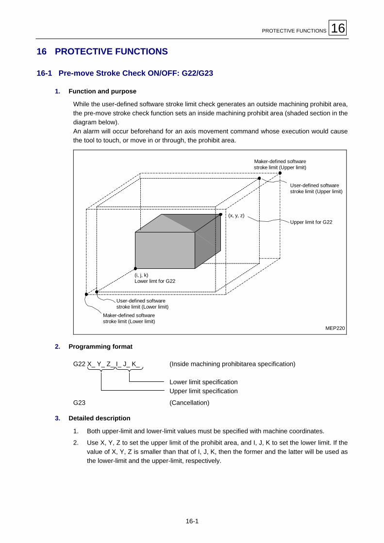
PROTECTIVE FUNCTIONS 16
16-1
16 PROTECTIVE FUNCTIONS
16-1 Pre-move Stroke Check ON/OFF: G22/G23
1. Function and purpose
While the user-defined software stroke limit check generates an outside machining prohibit area,the pre-move stroke check function sets an inside machining prohibit area (shaded section in thediagram below).An alarm will occur beforehand for an axis movement command whose execution would causethe tool to touch, or move in or through, the prohibit area.
MEP220
(x, y, z)
(i, j, k)Lower limt for G22
Maker-defined softwarestroke limit (Upper limit)
User-defined softwarestroke limit (Upper limit)
Upper limit for G22
User-defined softwarestroke limit (Lower limit)
Maker-defined softwarestroke limit (Lower limit)
2. Programming format
G22 X_ Y_ Z_ I_ J_ K_ (Inside machining prohibitarea specification)
Lower limit specificationUpper limit specification
G23 (Cancellation)
3. Detailed description
1. Both upper-limit and lower-limit values must be specified with machine coordinates.
2. Use X, Y, Z to set the upper limit of the prohibit area, and I, J, K to set the lower limit. If thevalue of X, Y, Z is smaller than that of I, J, K, then the former and the latter will be used asthe lower-limit and the upper-limit, respectively.

16 PROTECTIVE FUNCTIONS
16-2
3. No stroke limit checks will be performed if the upper- and lower-limit values that areassigned to one and the same axis are identical.
4. Give a G23 command to cancel the pre-move stroke limit check function.
5. A block of G23 X_Y_Z_ will cause the axis motion command X_Y_Z_ to be executed in thecurrent mode of axis movement after cancellation of pre-move stroke limit check.
Note: Before setting G22, move the tool to a position outside the prohibit area.
G22X200.Y250.Z100.I200.J-200.K0
The X-axis does not undergo the stroke check.
E

THREADING: G33 (Option) 17
17-1
17 THREADING: G33 (Option)
17-1 Equal-Lead Threading
1. Function and purpose
Setting a G33 command in the program enables equal-lead threading under tool feed controlsynchronized with spindle rotation.Also, multiple-thread screws can be machined by specifying the starting angle of threading. Ad’ANDREA tool is required for fully automatic threading.
2. Programming format
A. Standard lead threading
G33 Zz Ff Qqz: Threading direction axis address and the thread lengthf: Lead in the direction of the long axis (the axis to be moved through the longest distance
among all axes)q: Threading start shift angle (0 to 360 degrees)
(The starting angle of threading becomes 0 degrees if omitted.)
B. Precise lead threading
G33 Zz Ee Qqz: Threading direction axis address and the thread lengthe: Lead in the direction of the long axis (the axis to be moved through the longest distance
among all axes)q: Threading start shift angle (0 to 360 degrees)
(The starting angle of threading becomes 0 degrees if omitted.)
3. Detailed description
1. For a tapered screw, specify the lead in the long-axis direction.
MEP226
X
Z
Lz
Lx
a If a < 45°, then the lead must be Lz.If a > 45°, then the lead must be Lx.If a = 45°, then the lead can be either Lx or Lz.
Tapered thread
The setting ranges of leads F and E are as follows:
Input unit F-command lead data range (6-digit) E-command lead data range (8-digit)
Metric 0.001 to 99.9999 mm/rev. 0.00002 to 99.999999 mm/rev.
Inch 0.0001 to 9.99999 in./rev. 0.000002 to 9.9999999 in./rev.
Note: Alarm 134 SPINDLE ROTATION EXCEEDED will be displayed if the feed rate, afterbeing converted into a feed rate per minute, is in excess of the maximum cutting feedrate.

17 THREADING: G33 (Option)
17-2
2. The E-command data will also be used as number-of-threads command data for threadingin inches. Whether the command data is to be used only as precise lead data or number-of-threads data can be selected using bit 7 of parameter F91.
3. Keep the spindle speed constant during the entire machining cycle from rough cutting tofinish cutting.
4. During threading, feed hold does not work. Pressing the feed hold button during threadingbrings the program to a block stop at the end of the block which immediately succeeds theblock under the control of the G33 mode (that is, the block at which the threading operationhas ended).
5. For tapered screws, since machining cannot be stopped in the middle of threading, thecutting feed rate after being converted may exceed the maximum cutting feed according tothe particular command data.To prevent this from occurring, therefore, the command lead data must be set according tothe maximum feed rate obtained after conversion, not for the starting point of threading.
6. Usually, the leads at the beginning of threading and at the end of threading becomeincorrect because of a delay in the operation of the servo system. A thread length musttherefore be specified that has a probable, incorrect lead length added to the requiredthread length.
7. The spindle speed undergoes the following restriction:
1 ≤ R ≤Maximum feed rate
Thread lead
where R must be smaller than or equal to the maximum allowable encoder revolutions (rpm),and
R: Spindle speed (rpm)Thread lead: mm or inchesMaximum feed rate: mm/min or inches/min
8. The threading start shift angle must be specified using an integer from 0 to 360.
9. The cutting feed override value is fixed at 100%.

THREADING: G33 (Option) 17
17-3
4. Sample program
N110 G90G0X-200.Y-200.S50M3N111 Z110.N112 G33Z40.F6.0N113 M19N114 G0X-210.N115 Z110.M0N116 X-200. M3N117 G04X5.0:N118 G33Z40.
MEP227
X
X
Y
Z
10
10
50
<Operation description>
N110, N111 The spindle center is positioned at the workpiece center and the spindlerotates forward.
N112 The first threading operation is performed.Tread lead = 6.0 mm
N113 Spindle orientation based on an M19 command is performed.
N114 The tool moves away in the X-axis direction.
N115 The tool returns to a position above the workpiece, and an M00 commandstops the program. Adjust the tool as required.
N116 Preparations for the second threading operation are made.
N117 Set a dwell time, as required, to stabilize the spindle speed.
N118 The second threading operation is performed.

17 THREADING: G33 (Option)
17-4
17-2 Continuous Threading
Continuous threading becomes possible by setting threading command codes in succession inthe program. Thus, special threads that change in lead and/or shape during threading can bemachined. A D’ANDREA tool is required for continuous threading.
MEP228
G33G33
G33
17-3 Inch Threading
1. Function and purpose
Including in a G33-command format the number of threads per inch in the long-axis directionenables tool feed to be controlled in synchronization with spindle rotation, and thus enablesequal-lead straight threading and tapered threading.
2. Programming format
G33 Zz Ee Qq
z: Threading direction axis address and the thread lengthe: Number of threads per inch in the direction of the long axis (the axis to be moved through
the longest distance among all axes)(A decimal point can be included.)
q: Threading start shift angle (0 to 360 degrees)
3. Detailed description
1. The number of threads per inch must be that existing in the long-axis direction.
2. E-command data will also be used as command data for precise lead threading. Whetherthe command data is to be used only as number-of-threads command data or precise leadcommand data can be selected using bit 7 of parameter F91.
3. E-command data value must be in the setting range for the command.

THREADING: G33 (Option) 17
17-5
4. Sample program
Thread lead ........3 thread leads/inch (= 3.46666...)
δ1 = 10 mm δ2 = 10 mm
If programmed in millimeters:
N210 G90G0X-200.Y-200.S50M3N211 Z110.N212 G91G33Z-70.E3.0 (First threading)N213 M19N214 G90G0X-210.N215 Z110.M0N216 X-200. M3N217 G04X2.0N218 G91G33Z-70. (Second threading)
MEP227
X
X
Y
Z
δ1
δ2
50.0

17 THREADING: G33 (Option)
17-6
- NOTE -
E

DYNAMIC OFFSETTING: M173, M174 (Option) 18
18-1
18 DYNAMIC OFFSETTING: M173, M174 (Option)
1. Function and purpose
Machining with rotation of the rotary table (B-axis) requires in principle the axis of rotation of theworkpiece to be completely aligned with the axis of rotation of the table.
MEP232
Workpiecebefore machining
Workpieceafter machining
In practice, however, this is very difficult to implement for the reasons of fixture design, unless avery precise fixture is used.Dynamic offsetting is a function that internally compensates continuous deviation due to themisalignment in question. As a result, machining program can easily be prepared on theassumption that the alignment is ideal.
Axis of rotationof the table
Axis of rotationof the workpiece
B axis
X axis
Z axis
MEP233
M173 Dynamic offsetting ONG01 B360. F500M174 Dynamic offsetting OFF

18 DYNAMIC OFFSETTING: M173, M174 (Option)
18-2
2. Detailed description
1. Automatic limitation by the software does not occur even if dynamic offsetting may causethe stroke limit to be overstepped.
2. Reduce to 3 mm or less the eccentricity of an actually mounted workpiece from the axis ofrotation of the table; otherwise the alarm 137 DYNAMIC COMPENSATION EXCEEDED iscaused.Automatic operation is executed on the assumption that the origin of the workpiececoordinates lies on the axis of rotation of the workpiece. Manual operation uses the data inparameter I11 (as described later).
3. The workpiece origin must be set on the axis of rotation of a workpiece when it is to bemachined using dynamic offsetting.
4. Dynamic offsetting is not effective in the 3-dimensional coordinates conversion mode (G68).
5. The related parameters are as follows:
Address Name Setting Description
S5Axis of tablerotation
Set the machine coordinates of the axis of the table rotation for thecontrolled axes concerned.
I11Axis of work-piece rotation
Unit:0.001 mm
Range:±99999999
Set the machine coordinates of the axis of the workpiece rotation,existing at a table angle of 0 degrees, for the controlled axesconcerned. (This parameter is valid only for manual operation.)
6. Dynamic offsetting is provided for the type of machining that can in principle be achieved byturning the workpiece only with the tool in a fixed position.
Workpiece
Table
MEP234
3. Sample program
G55 .......................The workpiece axis is assumed to go through the origin of the G55 system.G0X_Y_Z_ ............ApproachM173.....................Dynamic offsetting ONG1Z_F_ ................Start of cutting
B_F_................B-axis rotationZ_F_................Relief on the Z-axis
M174.....................Dynamic offsetting OFFM30 .......................End of machining
E

HIGH-SPEED SMOOTHING CONTROL FUNCTION (OPTION) 19
19-1
19 HIGH-SPEED SMOOTHING CONTROL FUNCTION (OPTION)The high-speed smoothing control function allows rapid and highly accurate execution of anEIA/ISO program which is prepared to approximate free-curved surfaces with very small lines.Compared with the conventional high-speed machining mode, this function allows machiningalmost free of cut-surface defects and stripes.
The application of speed control based on a block-to-block angle, such as corner deceleration, inthe conventional high-speed machining mode may cause acceleration and deceleration to berepeated in too formal a response to minute steps or to errors. As a result, scratch-like traces orstripes may be left on a cut surface.
By judging the machining shape or contour from the specified continuous lines as well as fromthe angle between two blocks, the high-speed smoothing control conducts the optimum speedcontrol not affected too significantly by very slight steps or undulations. Consequently, a cutsurface with less scratch-like traces or stripes can be obtained.
Some of the outstanding features of high-speed smoothing control are listed below.
- Effective for machining a die of a smooth shape using a microsegment program.
- Speed control is insusceptible to the effects of any errors contained in the tool path.
- If adjacent paths are similar in terms of geometrical accuracy, acceleration and decelerationpatterns will also be similar.
- Even at the sections where corner deceleration is not necessary with respect to the angle,speed will be clamped if the estimated acceleration is great.
This function is valid during high-speed mode with the shape correction being selected.
For obtusecorners (<θ)
For sharpercorners (>θ)
θ
θ
Optimum deceleration at corners(conventional control)
High-speed smoothing control
Feed Feed
Time Time
No deceleration
Decelerationaccording to thecorner angle
Feed Feed
Time Time
D735P0563
θ = Reference angle fordeceleration at corners

19 HIGH-SPEED SMOOTHING CONTROL FUNCTION (OPTION)
19-2
19-1 Programming Format
G61.1 (G61.2);G5P2; ・・・・・・・High-speed machining mode (with smoothing control) ON
- Either 0 or 2 is to be set with address P (P0 or P2).
- No other addresses than P and N must be set in the same block with G05.
- Use the following parameter to make the high-speed smoothing control valid.
F3 bit 0 = 1: High-speed smoothing control valid0: High-speed smoothing control invalid (Only high-speed machining valid)
- Give G61.1 (Shape correction ON) or G61.2 (Modal spline interpolation) before G05P2 to usethe high-speed smoothing control.
19-2 Commands Available in the High-Speed Smoothing Control Mode
As is the case with the high-speed machining mode feature, only axis motion commands with thecorresponding preparatory functions (G-codes) and feed functions (F-codes), and designation ofsequence number are available in the high-speed smoothing control. Setting data of any othertype will result in an alarm (807 ILLEGAL FORMAT).
1. G-codes
The available preparatory functions are G00, G01, G02 and G03. The circular interpolation canbe programmed with R (radius designation) as well as with I and J (center designation), andexecuted always (independently of the setting in bit 2 of the F96 parameter) with the control for auniform feed.Moreover, the type of feed function can be selected even in the middle of the high-speedsmoothing control mode between G93 (Inverse time feed) and G94 (Asynchronous feed).However, synchronous feed (Feed per revolution; G95) is not available.
With the exception of group 1, the modal G-functions will be saved during, and restored uponcancellation of, the high-speed smoothing control mode.
2. Axis motion commands
The three linear axes (X, Y, Z) can be specified. Absolute data input as well as incremental datainput is applicable, indeed, but the former input mode requires the validation of bit 5 of the F84parameter.
F84 bit 5 : Type of position data input in the high-speed machining mode:1: The input mode (G90/G91) before selection of the high-speed machining mode0: Always incremental data input
3. Feed functions
The rate of feed can be specified with address F.
4. Sequence number
Sequence number can be specified with address N. This number, however, is skipped as ameaningless code during reading.

HIGH-SPEED SMOOTHING CONTROL FUNCTION (OPTION) 19
19-3
19-3 Additional Functions in the High-Speed Smoothing Control Mode
During high-speed smoothing control, fairing, although basically not required, can be made valid,as with normal high-speed machining mode.
1. Fairing function
If, in a series of linear paths, a protruding section exists in the CAM-created microsegmentmachining program, this protruding path can be removed and the preceding and following pathsconnected smoothly by setting parameter F96 bit 1 to “1”.
F96 bit 1: Faring function for the microsegment machining program1: Faring for a protruding path0: No faring
F103: Maximum length of a block to be removed for fairing
D735P0564
The effect of fairing
Before fairing After fairing
Fairing is also valid for a succession of protruding paths as shown below:
D735P0565
Before fairing In the middle of fairing After fairing

19 HIGH-SPEED SMOOTHING CONTROL FUNCTION (OPTION)
19-4
19-4 Related Parameters
The parameters related to this function are as follows:
Address Name Description
F3 bit 0 High-speed smoothingcontrol valid/invalid
0: Invalid,1: Valid.
F3 bit 1 Deceleration atstepped sections
0: No deceleration at very slightly stepped sections,1: Deceleration at all stepped sections.
Under the default setting (0), deceleration does not occur at very slight steps of5 microns or less since such steps are processed as errors in the programmedpath. For a machining program which requires all the described contours in it tobe respected as they are, set this parameter to 1 to obtain precise feed controlfor the as-programmed shape.
19-5 Remarks
1. The modal functions for tool diameter offset, mirror image, scaling, coordinate systemrotation, virtual axis interpolation, three-dimensional diameter offset and shaping functionshould have been cancelled beforehand to give a G05 P2 command. Otherwise, an alarmmay be caused or the modal function unexpectedly cancelled.
2. The high-speed smoothing control mode should be selected and cancelled with the toolsufficiently cleared from the workpiece since the selection and cancellation always cause adeceleration of feed motions.
3. Fairing function cannot be executed in the mode of single-block operation.
4. The high-speed smoothing control is not valid for rotational axes.
19-6 Related Alarms
The alarms related to this function are as follows:
AlarmNo. Alarm message Cause Remedy
807 ILLEGAL FORMAT An unavailable command code is givenin the G5P2 mode.
Check the machining program and makecorrections as required.
809 ILLEGAL NUMBERINPUT
The number of digits of the enterednumerical data is too large.
Check the machining program and makecorrections as required.
E

FUNCTION FOR SELECTING THE CUTTING CONDITIONS 20
20-1
20 FUNCTION FOR SELECTING THE CUTTING CONDITIONS
1. Function and purpose
The workpiece can be machined under the desired cutting conditions by specifying one of tenaccuracy levels (from FAST to ACCURATE). The accuracy level is to be specified either by anM-code in the machining program or from the CUTTING LEVEL SELECT window.
2. Selecting an accuracy level
A. Use of the M-codes
Use the following miscellaneous functions (M-codes) to select the desired one from among the10 accuracy levels (Level 1 for the highest speed and Level 10 for the highest accuracy):
M-code Highest speed
M821 Accuracy level 1
M822 Accuracy level 2
M823 Accuracy level 3
M824 Accuracy level 4
M825 Accuracy level 5
M826 Accuracy level 6
M827 Accuracy level 7
M828 Accuracy level 8
M829 Accuracy level 9
M830 Accuracy level 10 Highest accuracy
B. Programming example
G00G40G80G90G94G98G91G00G28Z0.G28X0.Y0.T1T2M6G00G90G54X182.15Y20.974S180M3G43H1Z100.M8Z5.M825 ← Selection of Accuracy level 5.G01Z-9.F400.G03X170.15Y0.189R24.F180.G01Y-0.189G02X152.793Y-20.144R20.15G01X152.186Y-20.229X151.573Y-20.315X150.96Y-20.4 : :

20 FUNCTION FOR SELECTING THE CUTTING CONDITIONS
20-2
Remark: See the corresponding section in the Operating Manual for the details of the CUT-TING LEVEL SELECT window.
Note: Since accuracy level adjustment is a special function for die machining, this functioncan be used only for machines capable of utilizing the intended purpose of the function.The CUTTING LEVEL SELECT window is not displayed for other machines.
E

TORNADO TAPPING (G130) 21
21-1
21 TORNADO TAPPING (G130)
1. Function and purpose
Tornado tapping cycle is provided to machine a tapped hole by one axial cutting motion with theaid of a special tool. While usual tapping cycles require multiple tools to be used in sequence,use of this cycle function spares tool change time as well as repetitive cutting motion in order toenhance the machining efficiency.
This cycle function is only available on machines equipped with the Y-axis control facility.
Note: Tornado tapping function requires the following parameter settings for macro-call G-codes:
J37 = 100009401 (Fixed value for the number of the macroprogram to be called fortornado tapping)
J38 = 130 (Fixed value for the number of the G-code to be used for macro call)J39 = 2 (Fixed value for the type of macro call)
2. Programming format
The following format refers to hole machining on the face [or O. D. surface].
G17 [or G19];G130 R_Z_D_T_V_F_H_I_J_K_Q_E_M1 [or M0];X [or Z] _Y_; (Setting of hole position)G67;
45°
J
VH
Z
E
R: Position of R-pointZ: Position of hole bottomD: Hole diameterT: Tool diameterV: Hole depthF: Feed rateH: Chamfering amountI: Pitch 1J: Pitch 2K: Bottom finishing (0: No, 1: Yes, Others: Yes)Q: Machining direction (0: CW, 1: CCW)E: Position of 2nd R-pointM: Hole machining axis (0: X, 1: Z or oblique)
Cutting surface
R
D
Hole machining axis
I
TEP300
- The chamfering angle is fixed at 45°.- Arguments D (hole diameter) and T (tool diameter) must satisfy the following condition:
D ≥ T ≥ D/2.- Argument K is used to select whether finishing is to be (K1) or not to be (K0) executed on the
bottom of the hole.- Set the hole position separately from the macro-call G-code (G130).- As is the case with usual fixed cycles, actual machining with axial movement can only be
executed for a block containing the hole position data.- Do not fail to set the code G67 as required to cancel the modal call.

21 TORNADO TAPPING (G130)
21-2
3. Description of movement
A. Hole machining
1. With chamfering
After moving from the current position to the R-point on the hole axis and then approachingto a point on the 2nd R-point level, chamfering is performed by a spiral-helical interpolationfirst, and then cylindrical machining is carried out to the bottom by a circular-helicalinterpolation.
2nd R-pointApproach point
Cuttingsurface
R-point
Pitch 2
Hole diameter
Pitch 1
ER
Chamfer
Initial point
TEP301
Cutting feedRapid traverse
Hole depth
2. Without chamfering
After moving from the current position to the R-point on the hole axis and then approachingthrough the hole radius and to a point on the 2nd R-point level, cylindrical machining iscarried out from the top to the bottom by a circular-helical interpolation.
2nd R-pointApproach point
R-point
Hole depth
ER
Initial point
Pitch 2
Cuttingsurface
TEP302
Cutting feedRapid traverse
Hole diameter

TORNADO TAPPING (G130) 21
21-3
B. Movement on the bottom
1. With bottom finishing
After cutting down to the bottom of the hole by helical interpolation, the tool performs acircular interpolation for full circle, and then escapes radially to the axis of the hole beforereturning in the axial direction to the initial point or R-point at the rapid traverse.
TEP303
Escape point
2. Without bottom finishing
After cutting down to the bottom of the hole by helical interpolation, the tool escapes radiallyto the axis of the hole while axially returning through quarter the pitch, and then returns inthe axial direction to the initial point or R-point at the rapid traverse.
TEP304
1/4 pitch
Escape point

21 TORNADO TAPPING (G130)
21-4
- NOTE -
E

HIGH-SPEED MACHINING MODE FEATURE (OPTION) 22
22-1
22 HIGH-SPEED MACHINING MODE FEATURE (OPTION)
1. Function and purpose
The high-speed machining mode feature allows high-speed execution of programs used for themachining of free-curved surfaces that have been approximated using very small lines.In high-speed machining mode, microsegment machining capabilities improve by several times,compared with conventional capabilities. This allows the same machining program to beexecuted at several times the original feed rate, and thus the machining time to be reducedsignificantly.Conversely, a machining program that has been approximated using lines of several fractions ofthe original segment length, can also be executed at the same feed rate, so more accuratemachining is possible.Combined use of the high-speed machining mode and the shape correction function allows moreaccurate machining to be implemented.If, moreover, a protruding section exists in the microsegment machining program, smoothinterpolation can be conducted automatically by removing this illegal path.
73129977
Y
Z
X
High-speed machining is available in the automatic operation modes: Memory, HD (Hard Disk),IC card and Ethernet.Even in the high-speed machining mode can be applied various operational functions: overridefunctions, cutting feed rate limit function, single-block operation function, dry run function,graphic trace function and high-precision control function.
The microsegment machining capability in the high-speed machining mode is as follows:
Operation mode Max. speed Conditions required
Memory operation 135 m/min (5315 IPM) None
HD operation 67 m/min (2638 IPM) With the POSITION display selected on the screen(see Note 2)
Ethernet operation 135 m/min (5315 IPM) Avoid unusual key operations (see Note 3)
IC card operation 135 m/min (5315 IPM) None

22 HIGH-SPEED MACHINING MODE FEATURE (OPTION)
22-2
The microsegment machining capability is restricted further by the functions used in, or appliedto, the program as shown below:
Fairing functionPreparatory functions
Not applied Applied
G01 Linear interpolation only 135 m/min (5315 IPM) 84 m/min (3307 IPM)
G02/G03 Circular interpolation included 33 m/min (1299 IPM)
G6.1 Fine-spline interpolation included 101 m/min (3976 IPM) 50 m/min (1969 IPM)
Note 1: The microsegment machining capabilities shown above refer to the case where three-axis simultaneous motion commands consist of 32 characters per block for a segmentlength of 1 mm.
Note 2: If the POSITION display should be changed to any other display during operation,program reading from the hard disk may be aborted to damage the surface to bemachined.
Note 3: If unusual operations, such as holding down any cursor/page key or a mouse button,are performed, program reading from the network may be aborted to damage thesurface to be machined.
Note 4: Before executing a microsegment machining program for hard disk operation orEthernet operation, terminate the commercially available software if it is being used.
Note 5: Since optimum corner deceleration occurs during the shape correction mode, themachining time may be longer than in other modes.
2. Programming format
G5 P2 High-speed machining mode ONG5 P0 High-speed machining mode OFF
Note: Both commands must be given in a single-command block.
3. Commands available in the high-speed machining mode
Only axis motion commands with the corresponding preparatory functions (G-codes) and feedfunctions (F-codes), and designation of sequence number are available in the high-speedmachining mode. Setting data of any other type will result in an alarm (807 ILLEGAL FORMAT).
1. G-codes
The available preparatory functions are G00, G01, G02 and G03.The circular interpolation can be programmed with R (radius designation) as well as with Iand J (center designation). If the machining program includes circular commands, however,make bit 2 of the F96 parameter valid.
F96 bit 2: Type of control for circular commands in the high-speed machining mode:0: Control for the specified speed (with acceleration/deceleration)1: Control for a uniform feed
2. Axis motion commands
The three linear axes (X, Y, Z) can be specified.Absolute data input as well as incremental data input is applicable, indeed, but the formerinput mode requires the validation of bit 5 of the F84 parameter.
F84 bit 5: Type of position data input in the high-speed machining mode:0: Always incremental data input1: According to the input mode before selection of the high-speed machining mode

HIGH-SPEED MACHINING MODE FEATURE (OPTION) 22
22-3
3. Feed functions
Feed rate can be specified with address F.
4. Sequence number
Sequence number can be specified with address N. This number, however, is skipped as ameaningless code during reading.
5. Sample program
G28 X0 Y0 Z0G90 G0X-100.Y-100.G43 Z-5.H03G01 F3000G05 P2 High-speed machining mode ONX0.1X0.1 Y0.001X0.1 Y0.002
M
X0.1 F200G05 P0 High-speed machining mode OFFG49 Z0M02
Note 1: Either 0 or 2 is to be set with address P (P0 or P2). Setting any other value will result inan alarm (807 ILLEGAL FORMAT).
Note 2: No other addresses than P and N must be set in the same block with G05.
Note 3: A decimal point must not be appended to address P.
Note 4: The maximum permissible length of one block is 30 characters.
4. Additional functions in the high-speed machining mode
A. Fairing function
If, in a series of linear paths, a protruding section exists in the CAM-created microsegmentmachining program, this protruding path can be removed and the preceding and following pathsconnected smoothly by setting parameter F96 bit 1 to “1”.
F96 bit 1: Fairing function for the microsegment machining program0: No fairing1: Fairing for a protruding path
F103: Maximum length of a block to be removed for fairing
Before fairing After fairing
When F84 bit 5 = 0:Incremental motion under G01
When F84 bit 5 = 1:Absolute motion under G01

22 HIGH-SPEED MACHINING MODE FEATURE (OPTION)
22-4
Fairing is also valid for a succession of protruding paths as shown below:
Before fairing After fairingIn the middle of fairing
B. Cutting feed limiting speed
In shape correction mode, the minimum of the cutting feed limiting speeds of the movable axes isset as the cutting feed limiting speed in the high-speed machining mode. Setting parameter F96bit 5 to “1”, however, allows the curvature of every curved section to be judged for limiting thespeed so as not to exceed the maximum available acceleration.
F96 bit 5: Type of cutting feed limiting speed for the high-speed machining mode0: Minimum of the cutting feed limiting speeds of the movable axes1: Limiting speed based on the radius of curvature
R If axial movement at the section of a largecurvature should be conducted withoutdeceleration, excessive acceleration will bedeveloped to cause a path error due to innercornering.
C. Deceleration at corners in the high-speed machining mode
In shape correction mode, automatic deceleration at corners of significantly large angle isprovided in general to ensure that the acceleration developed during cornering shall fall withinthe predetermined tolerance.A micro-length block between relatively longer blocks intersecting each other in a large angle inCAM-created microsegment machining programs, in particular, may cause the cornering speedto mismatch the surroundings and thus affect surface quality.Setting parameter F96 bit 4 to “1” will now allow corner judgment and deceleration withoutsuffering any effects of such a microblock.To use this function, however, the high-accuracy control option is required in addition to theoptional high-speed machining function.

HIGH-SPEED MACHINING MODE FEATURE (OPTION) 22
22-5
F96 bit 4: Type of corner judgment in the high-speed machining mode0: Always judging from the angle between adjacent blocks1: Judging after removing any microblock (if present between large-angle blocks)
F107: Reference length for microblock judgement
An adequate deceleration can be performedwithout suffering any effects of this microblock.
5. Restrictions
1. The modal functions other than that of G-code group 01 will be saved during, and restoredupon cancellation of, the high-speed machining mode, indeed; but the modal functions fortool diameter offset, mirror image, scaling, coordinate system rotation, virtual axisinterpolation and three-dimensional diameter offset should have been cancelled beforehandto give a G05 P2 command. Otherwise, an alarm may be caused or the modal functionunexpectedly cancelled.
Example: Main programG28 X0 Y0 Z0G90 G92 X0 Y0 Z100.G00 X-100.Y-100.G43 Z-10.H001 Movement under the conditions of G90, G00 and G43M98 H001G49 Z0 Movement under the conditions of G90 and G01G28 X0 Y0 Z0M02Subprogram (O001)N001 F3000G05 P2 High-speed machining mode ONG01 X0.1X-0.1 Y-0.001X-0.1 Y-0.002
M
X0.1G05 P0 High-speed machining mode OFFM99
2. In the high-speed machining mode there may occur a delay in display response sincepriority is always given to the processing for the automatic operation.
When F84 bit 5 = 0:Incremental motion under G01
When F84 bit 5 = 1:Absolute motion under G01

22 HIGH-SPEED MACHINING MODE FEATURE (OPTION)
22-6
3. The high-speed machining mode should be selected and cancelled by using commands ofG05 P2 and G05 P0, respectively, with the tool sufficiently cleared from the workpiece sincethe selection and cancellation always cause a deceleration of feed motions as shown below:
Command
Speed
X-577 Y-577 Z-577 !!!! G05P0 !!!!!!!!!!G05P2
4. Restrictions on programming and machine operation are listed in the following table:
": Valid, –: Invalid, err: Error
Specification
Classification SubclassificationStandard Mode
High-speed mode(Designation in the mode)
Maximum controllable axis quantity 14 14
Effective controllable axis quantity 14 7
Simultaneously controllable axis quantity 5 5
Axis name " " (")
Control axes
CT axis " " (")
Unit of input ABC ABC
Unit of programming " "Units of control
Unit-of-programming × 10 " "
Tape code ISO/EIA ISO/EIA
Label skip " – (–)
ISO/EIA automatic identification " " (")
Parity H " " (")
Parity V " " (")
Tape format " Refer to the programming format.
Program number " " (err)
Sequence number " " (")
Control IN/OUT " " (err)
Input formats
Optimal block skip " " (err)
Tape input buffer " " (")Buffers
Pre-read buffer " " (")
Absolute/inrcemental data input " " (err)
Inch/metric selection " " (err)Positioncommands
Decimal point input " " (")

HIGH-SPEED MACHINING MODE FEATURE (OPTION) 22
22-7
": Valid, –: Invalid, err: Error
Specification
Classification SubclassificationStandard Mode
High-speed mode(Designation in the mode)
Positioning " " (")
One-way positioning " – (err)
Linear interpolation " " (")
Circular interpolation " " (")
Helical cutting " – (err)
Spiral interpolation " – (err)
Virtual-axis interpolation " – (err)
Threading " – (err)
Plane selection " " (err)
Fine-Spline interpolation " " (err)
Interpolationfunctions
NURBS interpolation " – (err)
Rapid feed rate " " (")
Cutting feed rate " " (")
Synchronous feed " " (err)
Automatic acceleration/deceleration " " (")
Linear acceleration/deceleration beforecutting interpolation " " (err)
Cutting feed rate limitation Limitation in cuttingdirection
Minimum limiting speed of feed axes/According to curvature
Rapid feed override " " (")
No. 1 cutting feed override " " (")
No. 2 cutting feed override " " (")
Exact-stop mode " – (err)
Cutting mode " " (err)
Tapping mode " – (err)
Automatic corner override " –
Error detection " " (")
Feed functions
Override cancellation " "
Dwell in time " – (err)Dwell
Dwell in number of revolutions " – (err)
M-command " " (err)
M independent output command " – (err)
Optional stop " – (err)Miscellaneousfunction
No. 2 miscellaneous functions " " (err)
Spindle functions S-command " " (err)
T-command " " (err)
Tool operation time integration " " (")Tool functions
Spare-tool selection " " (–)
Tool-length offset " " (err)
Tool-position offset " – (err)
Tool-diameter offset " – (err)
3D-tool-diameter offset " – (err)
Tool-offset memory " " (")
Number of tool offset data sets " " (")
Programmed tool-offset input " – (err)
Tool offsetfunctions
Tool-offset number auto selection " " (err)

22 HIGH-SPEED MACHINING MODE FEATURE (OPTION)
22-8
": Valid, –: Invalid, err: Error
Specification
Classification SubclassificationStandard Mode
High-speed mode(Designation in the mode)
Fixed cycle for drilling " – (err)
Pattern cycle – – (–)
Subprogram control " " (err)
Variable command " – (err)
Figure rotation " – (err)
Coordinate rotation " – (err)
User macro " " (err)
User macro interruption " " (err)
Scaling " – (err)
Mirror image " – (err)
Geometric function " – (err)
Geometric function " – (err)
Program auxiliaryfunctions
Programmed parameter setting " err (err)
Watchdog-based reference-point return " " (–)
Memory-based reference-point return " " (–)
Automatic reference-point return " – (err)
#2/#3/#4 reference-point return " – (err)
Reference-point check " – (err)
Machine corrdinate system offset " – (err)
Workpiece coordinate system offset " – (err)
Local coordinate system offset " – (err)
Coordinate system setting " – (err)
Corrdinate system rotation setting " – (err)
Program restart " " (err)
Coordinatesystem setting
Absolute data detection " " (")
Backlash correction " " (")
Lost-motion correction " " (")
Memory-based pitch error correction " " (")
Memory-based relative position correction " " (")
Machine errorcorrection
Machine coordinate system correction " " (")
Emergency stop " " (")
Stroke end " " (")
Software limit " " (")
Programmed software limit " – (err)
Interlock " " (")
External deceleration " " (")
Protectionfunctions
Data protection " " (")

HIGH-SPEED MACHINING MODE FEATURE (OPTION) 22
22-9
!: Valid, –: Invalid, err: Error
Specification
Classification SubclassificationStandard Mode
High-speed mode(Designation in the mode)
Tape operation ! ! (–)
Memory operation ! ! (–)
MDI operation ! ! (!)
Jog feed ! – (!)
Incremental feed ! – (!)
Handle feed ! – (!)
Manual rapid feed ! – (!)
Handle interruption ! ! (!)
Auto/manual simultaneous ! ! (!)
HD operation ! ! (–)
IC card operation ! ! (–)
Operation modes
Ethernet operation ! ! (–)
Automatic-operation start ! ! (!)
Automatic-operation halt ! ! (!)
Single-block stop ! ! (!)
NC reset ! – (!)
External reset ! – (!)
All-axis machine lock ! ! (!)
Axis-by-axis machine lock ! ! (!)
Dry run ! ! (!)
Miscellaneous-function lock ! ! (!)
External controlsignals
Manual-absolute selection ! ! (–)
Control-unit ready ! ! (!)
Servo-unit ready ! ! (!)
Auto-run mode ! ! (!)
Auto-run in progress ! ! (!)
Auto-run halted ! ! (!)
Cutting feed in progress ! ! (!)
Tapping in progress ! – (–)
Threading in progress ! – (–)
Axis selected ! ! (!)
Axis-movement direction ! ! (!)
Rapid feed in progress ! ! (!)
Rewind ! ! (!)
NC alarm ! ! (!)
Reset ! ! (!)
Status outputsignals
Movement-command completed ! ! (!)
Manual tool-length measurement ! – (–)
Automatic tool-length measurement ! – (err)
Skip ! – (err)
Multi-step skip ! – (err)
Measurement aidfunctions
Manual skip ! – (err)
Servo off ! ! (!)
Follow-up ! ! (!)Axis controlfunctions
Control-axis removal ! ! (!)

22 HIGH-SPEED MACHINING MODE FEATURE (OPTION)
22-10
": Valid, –: Invalid, err: Error
Specification
Classification SubclassificationStandard Mode
High-speed mode(Designation in the mode)
External data input I/F " " (")
External data output I/F " " (")Data input/output
External data input/output " " (")
Setting/Display unit " " (")
Settings display " " (")
Search " " (err)
Check-and-stop " – (–)
MDI " " (")
Program restart " " (err)
Machining-time calculation " " (")
PC opening " " (")
Program-status display " " (")
Integrated-time display " " (")
Setting/displayfunctions
Graphics display " " (")
Multi-step skip " – (err)Program creation
Graphics check " " (")
Program-error display " " (")
Operation-error display " " (")
Servo-error display " " (")
Operation-stop-cause display " " (")
Servo monitor display " " (")
NC-PC I/O signal display " " (")
DIO display " " (")
Self-diagnostics
Keyboard-operation record " " (")
E

AUTOMATIC TOOL LENGTH MEASUREMENT: G37 (OPTION) 23
23-1
23 AUTOMATIC TOOL LENGTH MEASUREMENT: G37 (OPTION)
1. Function and purpose
When the tool for which command data has been assigned moves to a programmedmeasurement position, the NC system will measure and calculate any differential data betweenthe coordinates at that time and those of the programmed measurement position. Data thusobtained will become offset data for that tool.Also, if offsetting has already been performed for the tool, the current offset data will be furtheroffset, provided that after movement of that tool under an offset status to the requiredmeasurement position, the measurements and calculations of any differential coordinates showsome data to be further offset.At this time, further offsetting will occur for the tool offset data if only one type of offset data exists,or for the tool wear offset data if two types of offset data exist (tool length offsets and tool wearoffsets).
Note: This preparatory function cannot be used for VERSATECH machines.
2. Programming format
G37 Z_ (X_, Y_) R_ D_ F_
X, Y, Z: Address of the measurement axis and the coordinate of the measurement position
R: Distance from the starting point of movement at a measurement feed rate, to themeasurement position
D: The area where the tool is to stop moving
F: Measurement feed rate
If R, D, or F is omitted, respective parameter values will become valid.
3. Description of parameters
Parameter Description
F42 R-code command. Deceleration area
F43 D-code command. Measurement area
F44 F-code command. Measurement feed rate f
F72 Conditions for skipping based on EIA G37
See the Parameter List for further details.

23 AUTOMATIC TOOL LENGTH MEASUREMENT: G37 (OPTION)
23-2
4. Example of execution
MEP229
If H01 = 0T01T00M06G90G00G43Z0H01G37Z-600.R200.D150.F300
Coordinate to reach the measurement position= –500.01–500.01 – (–600) = 99.990 + 99.99 = 99.99Thus, H01 = 99.99
F
0
–100
–400
–500
–600
–ZD
D
R
Measuringinstrument
If H01 = 100T01T00M06G90G00G43Z-200.H01G37Z-600.F300
Coordinate to reach the measurement position= –600.01–600.01 – (–600) = –0.01100 + (–0.01) = 99.99Thus, H01 = 99.99
<Supplement>When the program shown above is executed,parameter F42 and F43 are set as follows:F42 (R-code command) : 25000 (25 mm)F43 (D-code command) : 2000 ( 2 mm)
MEP230
F
–200
–300
–400
–500
–Z
–600F43F42
F43Measuringinstrument

AUTOMATIC TOOL LENGTH MEASUREMENT: G37 (OPTION) 23
23-3
5. Detailed description
1. Machine action based on command G37
G28X0Y0Z0G90G0G43Zz1Hh0 ................................... [1]
G37Zz0Rr0Dd0Ff0..................................... [2], [3]
G0G90Zz1 ............................................... [4]
G28X0Y0Z0............................................ [5]
h0 : Offset number
z0 : Coordinate of the measurement point (measurement position)
r0 : Starting point of movement at measurement feed rate
d0 : The area where the tool is to stop movingf0 : Measurement feed rate
[1]
[2]
[5]
MEP231
[4]
[3] (f0) R (r0)
(zi)
Measurementpoint (Z0)
Machine zero point
Rapid feedMeasurementfeed rate
2. Sensor signals (Measurement Position Reached) also act as skip signals.
3. If the F-code value is 0, the feed rate becomes 1 mm/min.
4. Update offset data becomes valid from the Z-axis (measurement axis) command codes thatsucceed the block of G37.
5. The delay and dispersion in processing of sensor signals, except for the PLC side, is from 0to 0.2 msec for the NC side alone. Accordingly, the following measurement error may occur:
Maximum measurement error [mm]
= Measurement feed rate [mm/min] 160
0.2 [ms]1000
××
6. When a sensor signal is detected, although the coordinates of the machine position at thattime will be read, the machine will stop only after overruning through the distance equivalentto a servo droop.
Maximum amount of overrun [mm]
= Measurement feed rate [mm/min] 160
30.3 [ms]1000
××
30.3 [msec] if the position loop gain is 33.

23 AUTOMATIC TOOL LENGTH MEASUREMENT: G37 (OPTION)
23-4
7. If command G37 is executed in the single-block operation mode, the machine will come to asingle block stop after execution of the block that immediately succeeds the G37-containingblock.
Example: G0G90G43Z-200.H01 [1]G37Z-600.R25.D2.F10 [2]G0G90Z-200. [3]
6. Precautions
1. Alarm 889 G37 OPTION NOT FOUND will result if G37 is set for a machine that does nothave a mounted option for automatic tool length measurement.
2. Alarm 923 ILLEGAL COMMAND G37 AXIS will result if the block of G37 does not containaxis data or contains data of two or more axes.
3. Alarm 924 G37, H COMMANDS SAME BLOCK will result if an H code exists in the block ofG37.
4. Alarm 925 H CODE REQUIRED will result if G43 H_ does not exist before the block of G37.
5. Alarm 926 ILLEGAL G37 SIGNAL will result if input sensor signals occur outside apredetermined allowable measurement range or if a sensor signal is not detected on arrivalof the tool at the ending point of movement.
6. If a manual interruption operation has been carried out during movement of the tool at ameasurement feed rate, the program must be restarted only after returning that tool to theposition existing when the interruption operation was carried out.
7. Set G37 data or parameter data so that the following condition is satisfied:
Measurement point – Staring point > R-code valueor parameter r
> D-code valueor parameter d
8. If the R-code value, the D-code value and parameter d, mentioned in Item G above, are all0s, the program will come to a normal end only when the designated measurement pointand the sensor signal detection point agree. Alarm 926 ILLEGAL G37 SIGNAL will result inall other cases.
9. If the R-code value, the D-code value, parameter r, and parameter d, mentioned in Item Gabove, are all 0s, alarm 926 ILLEGAL G37 SIGNAL will result after the tool has beenpositioned at the designated measurement point, irrespective of whether a sensor signal isdetected.
10. Set G37 (automatic tool length measurement code) together with G43 H_ (offset numberassignment code).
G43 H_G37 Z_R_D_F_
Machine in its single-blockstop status at block [1]
Start button on
Block [2] executed
Block [3] executed
Machine replaced in itssingle-block stop status

AUTOMATIC TOOL LENGTH MEASUREMENT: G37 (OPTION) 23
23-5
11. If the offset data is tool offsets of type A, then automatic correction of tool data occurs, or ifthe offset data is tool offsets of type B, then automatic correction of tool wear offsetting dataoccurs.
Example: The TOOL OFFSET displays in both cases after offsetting of H1 = 100
TOOL OFFSET (Type A) TOOL OFFSET (Type B)
TOOL LENGTH
No. OFFSET No. OFFSET No. GEOMETRY WEAR
1 100 17 0 1 100 0
2 0 18 0 2 0 0
Beforemeasurement
3 0 19 0 3 0 0
TOOL LENGTH
No. OFFSET No. OFFSET No. GEOMETRY WEAR
1 110 17 0 1 100 10
2 0 18 0 2 0 0
Aftermeasurement
3 0 19 0 3 0 0
12. The distance from the machine zero point to the measurement point (skip sensor) is presetin register R2392 or R2393. Use this value as reference to set a coordinate using Z-, X-, orY-code command.
13. When this function is used for tool offsets of type B, the correct data will not be displayed ifthe wear offset value exceeds 100.
14. When executing this function in the presence of offset data, set the value of a D code to2mm or less to prevent damaging the measuring instrument.
15. When executing this function in the absence of offset data (offset data = 0), set the values ofan R code and a D code to those larger than the tool length of the tool to be measured. Also,in that case, before executing this function, make sure that the skip sensor in the measuringinstrument correctly operates.

23 AUTOMATIC TOOL LENGTH MEASUREMENT: G37 (OPTION)
23-6
- NOTE -
E

DYNAMIC OFFSETTING ΙΙ: G54.2P0, G54.2P1 - G54.2P8 (OPTION) 24
24-1
24 DYNAMIC OFFSETTING II: G54.2P0, G54.2P1 - G54.2P8 (OPTION)
1. Function and purpose
When a workpiece fixed on the turntable is to be machined with the rotation of the table, mis-matching between the workpiece reference position (program origin) and the origin of workpiececoordinates (center of rotation of the table) leads to an error in machining contour. Provided thatthe vector of a particular deviation from the center of rotation to the workpiece reference positionis given as a “reference”, the “Dynamic Offsetting ΙΙ” function will calculate for each command ofrotation the deviation vector for the designated angular motion in order to control the linear axesfor an adequate movement to the ending point as programmed with respect to the idealworkpiece origin, and thus to prevent the above-mentioned faulty machining from occurring.
2. Programming format
G54.2 Pn;
n: Dynamic offset number (1 to 8)Give a “G54.2 P0” command (n = 0) to cancel the dynamic offsetting function.
Cancellation is the initial state of the function (upon turning-on).
3. Definitions of terms
A. Deviation vector
The vector of a deviation from the center of rotation of the table (Wo: presupposed position of theworkpiece origin) to the actual origin of coordinates of the workpiece mounted on the table.
B. Dynamic offset
The offsetting vector (= deviation vector; whose direction depends upon the angular position ofthe table) for the ending point of each block containing a command of rotation.
C. Reference dynamic offset
A particular deviation vector entered as the reference for the calculation of dynamic offsets.Consists of the vector proper (measured and entered in three-axis component vectors) and thepositions (in machine coordinates) of the rotational and tilting axis for the measurement.

24 DYNAMIC OFFSETTING ΙΙ: G54.2P0, G54.2P1 - G54.2P8 (OPTION)
24-2
4. Operation description
A. Operation by a command of rotation in the G54.2 mode
In the G54.2 mode (modal group 23), which is selected by a “G54.2Pn” command, deviationvector (to be used in a vector addition for offsetting) is re-calculated for each command of tablerotation beforehand in order to create an adequate tool path for the block’s ending point asprogrammed with respect to the ideal workpiece origin.
D735S1101
Work offset (e.g. G54)
Mounted here.
Machine zero point
[Legend]W1: The ideal workpiece mounting position (the workpiece origin set on to the center of rotation of the table)W1’: The actual workpiece mounting position (vector Gs denotes the deviation from the ideal position)W2’: The position of the actual workpiece W1’ after a table rotation by θW2: The position of the ideally mounted workpiece W1 after a table rotation by θWo: The origin of workpiece coordinates (given by a corresponding preparatory function, such as G54)Gs: The reference deviation vector (to be registered in the NC unit as a reference dynamic offset.)G: The deviation vector for the rotation of the rotational axis by θa (a1, a1’): The starting point of the G1 (linear interpolation) microsegment commandb (b1, b2’): The ending point of the G1 (linear interpolation) microsegment command
With the measurement results of the reference dynamic offset (Gs) registered for workpiece Wfixed on the turntable, the selection (activation) of the G54.2 mode causes the tool to be shiftedby the deviation vector Gs from the current position, point a1 for example, to point a1’ (if bit 0 ofthe F87 parameter described later is set to “0”).
A succeeding command of “G1b1” (b1 = designation of a point with X-, Y-, and Z-coordinates)feeds the tool from a1’ to b1’ in the G1 mode (linearly). If, however, simultaneous motion of therotational axis is designated in the same block, “G1b1Cθ” for example, the tool is also fed linearlyfrom the current position a1’ to the offset position b2’ which is obtained by adding the deviationvector G internally calculated for the θ rotation to point b2, the ending point on the ideallymounted workpiece.

DYNAMIC OFFSETTING ΙΙ: G54.2P0, G54.2P1 - G54.2P8 (OPTION) 24
24-3
B. On-reset operation
When the system is reset, the dynamic offsetting mode is normally canceled.
It depends, however, on the setting of parameter F95 bit 7 whether or not dynamic offsetting iscanceled on system reset operations.
F95 bit 7 = 0: The dynamic offset is cleared and the G54.2 mode is also canceled.
= 1: The existing dynamic offset is held along with the G54.2 mode. When theautomatic operation is started again after resetting, the dynamic offsetting modeis active from the beginning of the program.
Note: When the dynamic offset is cleared by resetting, the tool will not move on the pathcorresponding to the cleared vector (even if bit 0 of the F87 parameter described lateris set to “0”).
C. Operation by the selection and cancellation of the G54.2 mode
When a G54.2Pn command is given, the deviation vector for the current position of the rotationalaxis is calculated and an offsetting movement is carried out on the linear axes by their respectivecomponents of the computed vector (dynamic offset). If an axis motion command is given in thesame block, the deviation vector for the ending point of that block is calculated and thecorresponding motion is performed from the current point to the dynamically offset ending point.
The cancellation command (G54.2P0) moves the tool by a vector reverse to the current dynamicoffset. If an axis motion command is given in the same block, the corresponding motion isperformed from the current point to the ending point as designated with workpiece coordinates (amovement including the cancellation of the dynamic offsetting).
The axis motion occurs according to the current modal function concerned (of G-code group 1).
D. Manual interruption in the G54.2 mode
The deviation vector does not change if automatic operation is stopped in the G54.2 mode (bysingle-block stop, etc.) and then a movement on the rotational axis carried out in manual mode.The re-calculation of the deviation vector for dynamic offsetting will not occur until a rotationalaxis motion command or another G54.2 command is given after setting the MDI or automaticoperation mode.
5. Input and output of the reference dynamic offset
A. Setting the reference dynamic offset by G10
G10 L21 Pn Xx Yy ・・・・・・αα ;
Use this format of programmed parameter input. Argument P (n) denotes a dynamic offsetnumber (1 to 8).According to the data input mode, absolute (G90) or incremental (G91), the designated axisvalue overwrites, or is added to, the current one.
B. Reading/writing the reference dynamic offset with system variables
System variable number = 5500 + 20 × n + m
n: Dynamic offset number (1 to 8)m: Axis number (1 to 6)
Use system variable #5510 to read the selected dynamic offset number (1 to 8).

24 DYNAMIC OFFSETTING ΙΙ: G54.2P0, G54.2P1 - G54.2P8 (OPTION)
24-4
C. Reading the machine coordinates of the center of table rotation with system variables
#5141: X-coordinate of the center of table rotation (Machine parameter S5 X)#5142: Y-coordinate of the center of table rotation (Machine parameter S5 Y)#5143: Z-coordinate of the center of table rotation (Machine parameter S5 Z)
6. Other detailed precautions
1. When the related parameters and reference dynamic offset are modified in the G54.2 mode,the modifications will become valid for the next G54.2Pn command onward.
2. The following describes how some specific commands are executed in the G54.2 mode.
(a) Machine coordinate system selection (G53)A G53 command temporarily suppresses the dynamic offset and the axis motion isperformed to the ending point as designated in machine coordinates. The deviationvector is not re-calculated even when a value for the rotational axis is specified. Thedynamic offsetting function will not be recovered until a motion command is given withworkpiece coordinates.
(b) Workpiece coordinate system change (G54 to G59, G54.1, G92, G52)Even when the workpiece coordinate system is changed in the G54.2 mode, thereference dynamic offset is not re-calculated and dynamic offsets are calculatedaccording to the existing reference dynamic offset. The axis motion is carried out to theposition obtained by adding the deviation vector to the ending point specified in thenew workpiece coordinate system.
(c) Commands related to zero point return (G27, G28, G29, G30, G30.n)The dynamic offsetting function is temporarily canceled for the path from the inter-mediate point to the reference point and recovered for the movement from there to aposition specified in the workpiece coordinate system. (Similar to the processing of thecommands related to zero point return in the tool length offset mode)
3. When the work offset data (workpiece origin) being used is modified by a G10 command inthe G54.2 mode, the new work offset data will be valid for the next block onward.
4. As for the tool motion caused by a change only in the deviation vector, it is executed in thecurrent mode of G-code group 1 and at the current rate of feed. If, however, the modeconcerned is other than that of G0 or G1, e.g. a mode of circular interpolation (G2, G3, etc.),the tool is temporarily moved in the mode of linear interpolation (G1).
5. The type of the control axis for the turntable must be specified as “rotational”. The dynamicoffsetting function ΙΙ cannot be used for the C-axis specified as “linear type”.
6. The polar coordinate interpolation with the rotational axis cannot be executed properly in theG54.2 mode.
7. The following function commands cannot be executed in the G54.2 mode:- Restarting the program- Mirror image (by G51.1 or control signal)- Scaling (G51)- Figure rotation (M98)- Coordinates rotation (G68)- G61.1, G61.2, G5P0, G5P2
8. The workpiece coordinates read with system variables include dynamic offsets.
9. The component vectors of the current dynamic offset can be read using system variables#5121 (X-axis), #5122 (Y-axis) and #5123 (Z-axis).

DYNAMIC OFFSETTING ΙΙ: G54.2P0, G54.2P1 - G54.2P8 (OPTION) 24
24-5
7. Related alarms
936 OPTION NOT FOUNDThe dynamic offset ΙΙ option is not installed.
959 WORKPIECE COORDINATE ERRORThe origin of workpiece coordinates does not match the center of rotation of the turntable.
807 ILLEGAL FORMATArgument P is missing in the block of G54.2.An incompatible G-code is used in the G54.2 mode or G54.2 is given in the mode of anincompatible G-code.
809 ILLEGAL NUMBER INPUTThe value of P in the block of G54.2 is not proper.
8. Related parameters
A. Rotational axis configuration
Specify the type of rotational axis configuration of the machine to be operated.
L81 = 0: Makes the dynamic offsetting function invalid.= 1: Two rotational axes (C-axis on A-axis)= 2: One rotational axis (A-axis)= 3: One rotational axis (C-axis)= 4: One rotational axis (B-axis)
Specify “1” for the VARIAXIS series, and “4” for the FH/PFH series with an NC rotary table.
B. Dynamic offset type
Specify whether or not the tool is to be offset by each change only in the deviation vector.
F87 bit 0 = 0: Offset (the indication of both workpiece and machine coordinates changes.)= 1: Not offset (no change in the position indication at all)
Normally set this parameter to “0”.
C. Center of table rotation
Specify the center of rotation of the table in machine coordinates. These parameters are alsoused in the VARIAXIS control for MAZATROL programs.
The preset values refer to the factory adjustment at Mazak.
S5 X, Y Center of rotation of the turntable (Machine coordinates)S12 Y, Z Axis of rotation of the tilting table (Machine coordinates)S11 Z Distance (length) from the tilting axis to the turntable surface
(The turntable center must be in the direction of –Z from the tilting axis.)
Note: When L81 = 2, 3, or 4, the S11 and S12 settings are not required.
D. Workpiece origin mismatch check
The origin of the selected workpiece coordinate system must correspond to the center of tablerotation in order that the dynamic offsetting may effectively function. The following parameter isprovided to check the condition in question for each G54.2 command.
F87 bit 1 = 0: The mismatch check is conducted.= 1: The mismatch check is not conducted.
Normally set this parameter to “0”.

24 DYNAMIC OFFSETTING ΙΙ: G54.2P0, G54.2P1 - G54.2P8 (OPTION)
24-6
9. Mechanical requirements
The dynamic offsetting function requires the following conditions to be satisfied:
1. The machine is equipped with a table of either two-axis rotational control (construction of aturntable on the tilting axis) or of a single rotational axis control (turntable or tilting table).The tilting and rotational axis must refer to rotating around the X- and Z-axis, respectively.Moreover, the construction must not be of the tilting axis mounted on the turntable.
2. The workpiece coordinate origin corresponds to the center of table rotation, and the X-, Y-,and Z-axes of workpiece coordinates are in parallel with, and the same direction as, thecorresponding axes of machine coordinates.
3. The requirements for machining with table rotation: The machining contour is describedusing a workpiece coordinate system fixed in parallel with the machine coordinate system(not rotated with the table rotation) and microsegment command blocks of G1.
10. Operation description using a sample program
The following describes the operation using a sample program (created for explanation only).
A. Settings on the related displays
WORK OFFSET (G54) X = –315.0, Y = –315.0, Z = 0.0, A = 0.0, C = 0.0
DYNAMIC OFFSET (P1) X = –1.0, Y=0.0, Z = 0.0, A = 0.0, C = 90.0
Parameters L81 = 1 (Rotational axis configuration: Two rotational axes; C-axis on A-axis)F87 bit 0 = 0 (Dynamic offset type: Offset)S5 X = –315000S5 Y = –315000
B. Sample program (for explanation of operation)
N1 G91 G28 X0 Y0 Z0 A0 C0N2 G54N3 G90 G00 X0 Y0 Z0 A0 C0N4 G54.2P1N5 G01 C180.0 F1000N6 G01 X10.0N7 G03 X0 Y10.0 R10.0N8 G01 C240.0
C. Position indication and dynamic offset for each line of the program
POSITION (workpiece coordinates) MACHINE (machine coordinates) Dynamic offsetN-No.
X Y Z A C X Y Z A C X Y Z
N1 0.000 0.000 0.000 0.000 0.000 0.000 0.000 0.000 0.000 0.000 0.000 0.000 0.000
N2 315.000 315.000 0.000 0.000 0.000 0.000 0.000 0.000 0.000 0.000 0.000 0.000 0.000
N3 0.000 0.000 0.000 0.000 0.000 –315.000 –315.000 0.000 0.000 0.000 0.000 0.000 0.000
N4 0.000 –1.000 0.000 0.000 0.000 0.000 –316.000 0.000 0.000 0.000 0.000 –1.000 0.000
N5 0.000 1.000 0.000 0.000 180.000 0.000 –314.000 0.000 0.000 180.000 0.000 1.000 0.000
N6 10.000 1.000 0.000 0.000 180.000 –305.000 –314.000 0.000 0.000 180.000 0.000 1.000 0.000
N7 0.000 11.000 0.000 0.000 180.000 –315.000 –304.000 0.000 0.000 180.000 0.000 1.000 0.000
N8 0.866 10.500 0.000 0.000 240.000 –314.134 –325.500 0.000 0.000 240.000 0.866 0.500 0.000

DYNAMIC OFFSETTING ΙΙ: G54.2P0, G54.2P1 - G54.2P8 (OPTION) 24
24-7
D. Illustration of the sample program
Measurement of the reference dynamic offset
Workpiece
Turntable (C-axis)
Let the position where the ! mark on the table is alignedwith the fixed position marked with " be the zero point ofthe C-axis.The reference dynamic offset (arrow) = (–1, 0, 0) wasmeasured with the table positioned at C = 90.0, asshown on the left.
N-No. N3 N4 N5
Illustration
1 2 3
N-No. N6, N7 N8 N5
Illustration
4 5
<Explanation>
1. N3 turns the table on the C-axis to ! (C = 0) and positions the tool tip to the × point (X, Y, Z = 0, 0, 0).2. N4 causes the tool tip to be shifted by the dynamic offset (arrow) for an angular position of C = 0 to the × point
(X, Y, Z = 0, –1, 0).3. N5 turns the table on the C-axis to ! (C = 180) and causes the tool tip to be shifted by linear interpolation to the ×
point (X, Y, Z = 0, 1, 0) determined by the dynamic offset (arrow) for an angular position of C = 180.4. N6 and N7 interpolate the linear and circular paths to the × point.5. N8 turns the table on the C-axis to ! and causes the tool tip to be shifted by linear interpolation to the × point.

24 DYNAMIC OFFSETTING ΙΙ: G54.2P0, G54.2P1 - G54.2P8 (OPTION)
24-8
- NOTE -
E

EIA/ISO PROGRAM DISPLAY 25
25-1
25 EIA/ISO PROGRAM DISPLAYThis chapter describes general procedures for and notes on constructing an EIA/ISO programnewly, and then editing functions.
25-1 Procedures for Constructing an EIA/ISO Program
(1) Press the display selector key.
(2) Press the [PROGRAM] menu key.
! The PROGRAM display will be selected.
(3) Press the [WORK No.] menu key.
! WORK No. is displayed in reverse to show the window of work number list.
Remark: Refer to the Operating Manual for the window of work number list.
(4) Enter the new work number of a program to be constructed.
- Specifying a work number of a program registered already in NC unit allows the programto be displayed on the screen. Therefore, constructing a new program requires specifyinga work number which has not been used. The conditions how work numbers are used aredisplayed on the window of work number list.
(5) Press the [EIA/ISO PROGRAM] menu key.
- Press the [PROGRAM EDIT] menu key instead of [EIA/ISO PROGRAM] if a work numberof the program already registered has been set in Step (4).
Cursor
(6) Enter the required programming data.
Set data using alphabetic keys, numeric keys and INPUT key INPUT .
- When INPUT key INPUT is pressed, the cursor is moved to the top of the next line, and thenthe data of the next block can be entered.
(7) Press the [PROGRAM COMPLETE] menu key to end the editing.

25 EIA/ISO PROGRAM DISPLAY
25-2
25-2 Editing Function of EIA/ISO PROGRAM Display
25-2-1 General
Establishing a constructing mode on the PROGRAM (EIA/ISO) display allows the followingmenu to be displayed as an initial one.
[1] [2] [3] [4] [5] [6]
Terms [1] to [6] represent functions related to the program editing. Use of the functions permitsthe following operations:
- Inserting and altering data at any positionData can be inserted and altered at any position on the display.
- Erasing the dataData displayed on the display can be erased.
- Searching for the dataData can be searched in the following four ways.
1) Searching for the top line of the program2) Searching for the bottom line of the program3) Searching for any required line of the program4) Searching for any character string
- Copying the dataOther EIA/ISO programs registered in the NC unit can be copied into the selected program, orany data character string in the selected program can be copied into a given position of theselecting program or a new EIA/ISO program.
- Moving the dataAny data character string can be moved to a given position of the selecting program or a newEIA/ISO program.
- Replacing the dataAny data character string can be replaced by another character string.
25-2-2 Operation procedure
The procedure for each operation is described below.(Given that EIA/ISO program, in which several lines of data are already provided, is selected,and editing mode is established, and also that ALTER menu item is not displayed in the reversestatus in the operations 3 and onward.)
1. Inserting the data
(1) Press the [ALTER] menu key as required to obtain the display status ALTER.
- When ALTER is displayed, press the menu key to cancel the reverse-display status.
(2) Move the cursor to the position where data must be inserted.
- The cursor can be moved to any direction (vertically and horizontally).
(3) Enter the required data.
! Data is inserted in sequence into the position where the cursor is placed.
! Data previously set behind the cursor position are moved behind the inserted data.

EIA/ISO PROGRAM DISPLAY 25
25-3
2. Altering the data
(1) Press [ALTER] menu key to display ALTER.
- When ALTER is displayed, press the menu key to reverse the display status.
(2) Move the cursor to the position where data must be altered.
- The cursor can be moved to any direction (vertically and horizontally).
(3) Enter the required data.
! Data is altered in sequence from the position where the cursor is placed.
! The character previously set at the cursor position is replaced in sequence by the newdata.
3. Erasing the data
(1) Move the cursor to the head of the character string to be erased.
(2) Press the [ERASE] menu key.
! The character at the cursor position is displayed in reverse and the [ERASE] menuitem is also displayed in reverse.
(3) Move the cursor to the position next to the end of the character string to be erased.
! The portion from the head of the character string specified in (1) to the position beforethe cursor is displayed in reverse, which indicates that the reversed portion providesthe object of erasure.
Example: N001 G00 X10. IZ10.; G00 X100. G00 Z20.IN002 M08 M03
(4) Press the input key.
! The character string displayed in reverse in (3) is erased.
Example:
N001 G00 X10.N002 M08 M03
4. Searching for the data
A. Searching for the top line of the program
(1) Press the [SEARCH] menu key.
(2) Press the [PROG HEAD] menu key.
! The cursor moves to the top line.
B. Searching for the bottom line of the program
(1) Press the [SEARCH] menu key.
(2) Press the [PROG END] menu key.
! The cursor moves to the bottom line.
Cursor
Cursor positionin (1)

25 EIA/ISO PROGRAM DISPLAY
25-4
C. Searching for any required line of the program(1) Press the [SEARCH] menu key.
(2) Press the [SEARCH LINE No.] menu key.
! SEARCH LINE No. is displayed in reverse.
(3) Set the line No. of the line to be searched for.
- Enter the line No. with numeric keys, and press the input key.
! The cursor moves to the specified line.
D. Searching for any character string(1) Press the [SEARCH] menu key.
(2) Press the [SEARCH FORWARD] menu key or [SEARCH BACKWARD] menu key.
! SEARCH FORWARD or SEARCH BACKWARD is displayed in reverse.
- To search for a character string in the area before the cursor position, press the [SEARCHFORWARD] menu key, and for the area after the cursor position, press [SEARCHBACKWARD] menu key.
(3) Set the character string to be searched for and press the input key.
! The cursor moves to the head of the character string which has been found first.
- Press the data cancellation key (CANCEL) to stop halfway the searching operation, whoserunning state is indicated by the message CNC BUSY on the display.
Remark: Pressing the input key in sequence allows the cursor to move to the character stringwhich has been found next.
5. Copying the data
A. Copying a program(1) Move the cursor to the position where the program is to be copied.
(2) Press the [COPY] menu key.
(3) Press the [PROGRAM COPY] menu key.
! The window of work number list is displayed and the [PROGRAM COPY] menu item isdisplayed in reverse.
(4) Set the work number of the program to be copied and press the input key.
! The program is inserted into the cursor position.
Note: MAZATROL programs cannot be copied.
B. Copying any character string into the selected program
(1) Move the cursor to the head of the character string to be copied.(2) Press the [COPY] menu key.

EIA/ISO PROGRAM DISPLAY 25
25-5
(3) Press the [LINE(S) COPY] menu key.! The character at the cursor position is displayed in reverse and the [LINE(S) COPY]
menu item is also displayed in reverse.
(4) Move the cursor to the position next to the end of the character string to be copied.! The portion from the head of the character string specified in (1) to the position before
the cursor is displayed in reverse, which indicates that the reversed portion providesthe object of copying.
Example: N001 G00 X10. IZ10.
G00 X100.G00 Z20.
IN002 M08M03
(5) Press the input key.! The area displayed in reverse is established as the object to be copied.
(6) Move the cursor to the position where the character string is to be copied.! The cursor only moves, and the area displayed in reverse does not change.
Example:
N001 G00 X10. Z10.G00 X100.G00 Z20.
N002 M08IM03
(7) Press the input key.
! The character string displayed in reverse is copied at the cursor position.
Example: (Continued)N001 G00 X10.Z10. G00 X100. G00 Z20.N002 M08Z10. G00 X100. G00 Z20. M03
C. Copying any character string into a new program
(6) First, carry out Steps (1) to (5) of B. Set the workpiece number of a new program where thecharacter string is to be copied and press the input key.! The character string is copied in the new program, and the area displayed in reverse is
returned to normal display.
Remark: Pressing the [PROGRAM FILE] menu key allows the window of program list to bedisplayed.
Cursor
Cursor position in (1)
Cursor

25 EIA/ISO PROGRAM DISPLAY
25-6
6. Moving the data
A. Moving the selected program to any position
(1) Move the cursor to the head of the character string to be moved.
(2) Press the [MOVE] menu key.
! The character at the cursor position and the [MOVE] menu item is also displayed inreverse.
(3) Move the cursor to the position next to the end of the character string to be moved.
! The portion from the head of the character string specified in (1) to the position beforethe cursor is displayed in reverse, which indicates that the reversed portion providesthe object of moving.
N001 G00 X10. IZ10.G00 X100.G00 Z20.I
N002 M08M03
(4) Press the input key.
! The area displayed in reverse is established as the object to be moved.
(5) Move the cursor to the position where the character string is to be moved.
! The cursor only moves, and the area displayed in reverse does not change.
Example: (Continued)
N001 G00 X10. Z10.G00 X100.G00 Z20.
N002 M08IM03
(6) Press the input key.
! The character string displayed in reverse is moved to the cursor position.
Example: (Continued)
N001 G00 X10.N002 M08Z10. G00 X100. G00 Z20. M03
B. Movement to a new program
(5) First, carry out Steps (1) to (4) of A. Set the work number of a new program where thecharacter string is to be moved and press the input key.
! The character string is moved to the new program.
Remark: Pressing the [PROGRAM FILE] menu key allows the window of program list to bedisplayed.
Cursor position in (1)
Cursor
Cursor

EIA/ISO PROGRAM DISPLAY 25
25-7
7. Replacing the data
(1) Move the cursor to the starting position of data replacement.
- Replacement is made downward from the cursor position. To make replacement through-out the program, therefore, move the cursor to the first character of the top line.
(2) Press the [FIND & REPLACE] menu key.
! FIND & REPLACE is displayed in reverse.
(3) Set the character string before replacement.
- Enter the character string to be replaced using alphanumeric keys, and press the tab key.
(4) Set the new character string after replacement using alphanumeric keys, and press theinput key.
! The cursor moves to the head of the character string before replacement that has beenfound first after the cursor position specified in (1).
(5) Press the [REPLACE] menu key.
! The character string before replacement at the cursor position is replaced by thecharacter string after replacement, and the cursor moves to the head of the nextcharacter string before replacement. Pressing the [REPLACE] menu key in sequenceallows the character string before replacement to be replaced in order of being found.
When replacing the special character string at the cursor position is not required, press the [NOREPLACE] menu key in place of [REPLACE] menu key.
Remark 1: To stop the replacement, press the [END] menu key.
Remark 2: To replace all the character strings in the program, press the [NEXT] menu key.
Remark 3: Press the data cancellation key (CANCEL) to stop halfway the total replacement bythe NEXT menu function, whose running state is indicated by the message CNCBUSY on the display.

25 EIA/ISO PROGRAM DISPLAY
25-8
25-3 Macro-Instruction Input
This function permits entering the macro-instruction word by word for editing the EIA/ISOprogram efficiently.
(1) Press the [MACRO INPUT] menu key.
! The MACRO INPUT window will be opened.
- The character string selected with the cursor is usable.
(2) Move the cursor to the characters corresponding to the required macro-instruction andpress the input key.
! The macro-instruction is entered in the editing zone of the program.
(3) Press the menu selector key to display the menu for normal data input, and continueprogram editing.

EIA/ISO PROGRAM DISPLAY 25
25-9
25-4 Division of Display (Split Screen)
1. Dividing the screen (vertically)
(1) Temporarily cancel the editing mode, if selected, by pressing the [PROGRAM COMPLETE]menu key.
(2) Press the [DISPLAY 2 PROGRAM] menu key.
! The display of the menu item will be highlighted and the work number listing windowwill appear.
(3) Select the work number of the program to be displayed.
! The screen will be divided into the left and right part. One and the same section of theprogram is initially displayed in both parts.
D740PB002E
- The editing operation can only be carried out in the part the title (WNo.) of which is highlighted.
- The display contents in the other part will remain unchanged even after the editing in the activepart. Press the [CHANGE PROGRAM] menu key to change the display in the other partaccording to the editing operation.

25 EIA/ISO PROGRAM DISPLAY
25-10
2. Cancelling the division
(1) Temporarily cancel the editing mode, if selected, by pressing the [PROGRAM COMPLETE]menu key.
(2) Press anew the [DISPLAY 2 PROGRAM] menu key.
! The highlighted display of the menu item will be released and the division of the screencancelled.
D740PB003E
3. Changing the active part
The editing is only possible for the part whose title (WNo.) is currently highlighted. The method tochange the active part is indicated below.The data after the editing will not be displayed in the other part (of the same WNo.) unless thischanging operation is carried out.

EIA/ISO PROGRAM DISPLAY 25
25-11
In the example below, the left-hand part is currently active.
D740PB002E
(1) Press the [CHANGE PROGRAM] menu key.
! The highlighting of the title will be transferred from the left-hand to the right-hand part toindicate that the latter has been made active.
- The contents in the right-hand part will have been modified at the same time according tothe editing operation performed for the left-hand part (of the same WNo.).
D740PB004E
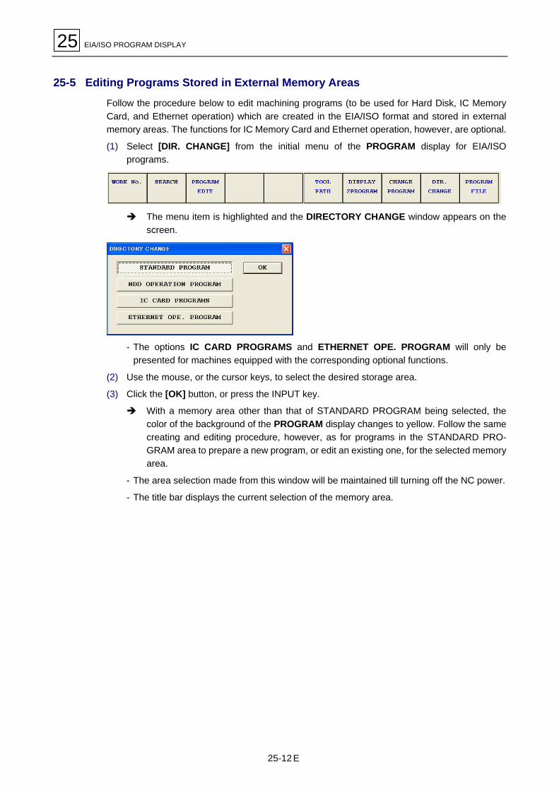
25 EIA/ISO PROGRAM DISPLAY
25-12
25-5 Editing Programs Stored in External Memory Areas
Follow the procedure below to edit machining programs (to be used for Hard Disk, IC MemoryCard, and Ethernet operation) which are created in the EIA/ISO format and stored in externalmemory areas. The functions for IC Memory Card and Ethernet operation, however, are optional.
(1) Select [DIR. CHANGE] from the initial menu of the PROGRAM display for EIA/ISOprograms.
! The menu item is highlighted and the DIRECTORY CHANGE window appears on thescreen.
- The options IC CARD PROGRAMS and ETHERNET OPE. PROGRAM will only bepresented for machines equipped with the corresponding optional functions.
(2) Use the mouse, or the cursor keys, to select the desired storage area.
(3) Click the [OK] button, or press the INPUT key.
! With a memory area other than that of STANDARD PROGRAM being selected, thecolor of the background of the PROGRAM display changes to yellow. Follow the samecreating and editing procedure, however, as for programs in the STANDARD PRO-GRAM area to prepare a new program, or edit an existing one, for the selected memoryarea.
- The area selection made from this window will be maintained till turning off the NC power.
- The title bar displays the current selection of the memory area.
E