Embed Size (px)
Citation preview
MAXI-CAST RESINTRANSFORMERSMAXI-CAST RESINTRANSFORMERS
TM
A GROUP CBS COMPANY

3
TM
CONTENTS
Introduction......................................................4
Application........................................................4
MAXI-CAST Transformer View......................5
Features..........................................................6-7
Section View......................................................8
Construction................................................9-11
Quality Assurance..........................................11
Technical Data ...........................................12-13
Specifications .................................................14
Many models and sizesavailable from stock forsame day shipment!
4
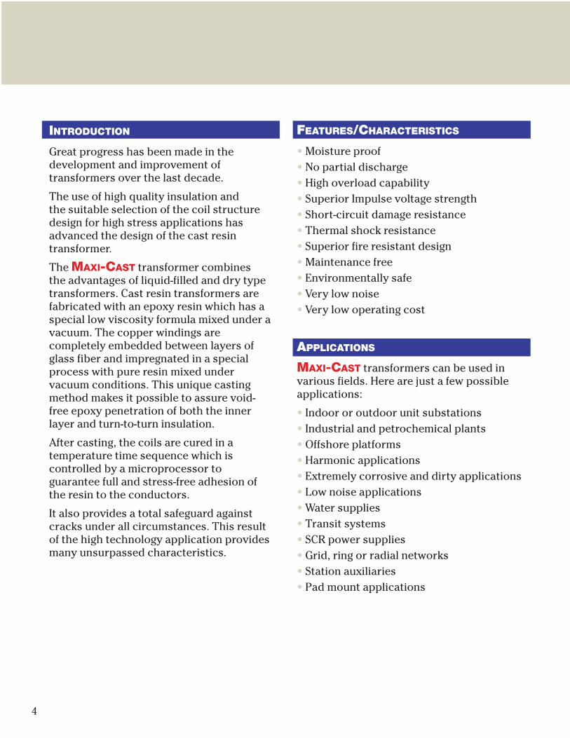
INTRODUCTION
Great progress has been made in thedevelopment and improvement oftransformers over the last decade.
The use of high quality insulation and the suitable selection of the coil structuredesign for high stress applications hasadvanced the design of the cast resintransformer.
The MAXI-CAST transformer combines the advantages of liquid-filled and dry typetransformers. Cast resin transformers arefabricated with an epoxy resin which has aspecial low viscosity formula mixed under avacuum. The copper windings arecompletely embedded between layers ofglass fiber and impregnated in a specialprocess with pure resin mixed undervacuum conditions. This unique castingmethod makes it possible to assure void-free epoxy penetration of both the innerlayer and turn-to-turn insulation.
After casting, the coils are cured in atemperature time sequence which iscontrolled by a microprocessor toguarantee full and stress-free adhesion ofthe resin to the conductors.
It also provides a total safeguard againstcracks under all circumstances. This resultof the high technology application providesmany unsurpassed characteristics.
FEATURES/CHARACTERISTICS
• Moisture proof• No partial discharge• High overload capability• Superior Impulse voltage strength• Short-circuit damage resistance• Thermal shock resistance• Superior fire resistant design• Maintenance free• Environmentally safe• Very low noise • Very low operating cost
APPLICATIONS
MAXI-CAST transformers can be used invarious fields. Here are just a few possibleapplications:
• Indoor or outdoor unit substations• Industrial and petrochemical plants• Offshore platforms• Harmonic applications• Extremely corrosive and dirty applications • Low noise applications• Water supplies• Transit systems• SCR power supplies• Grid, ring or radial networks • Station auxiliaries• Pad mount applications
5
TM
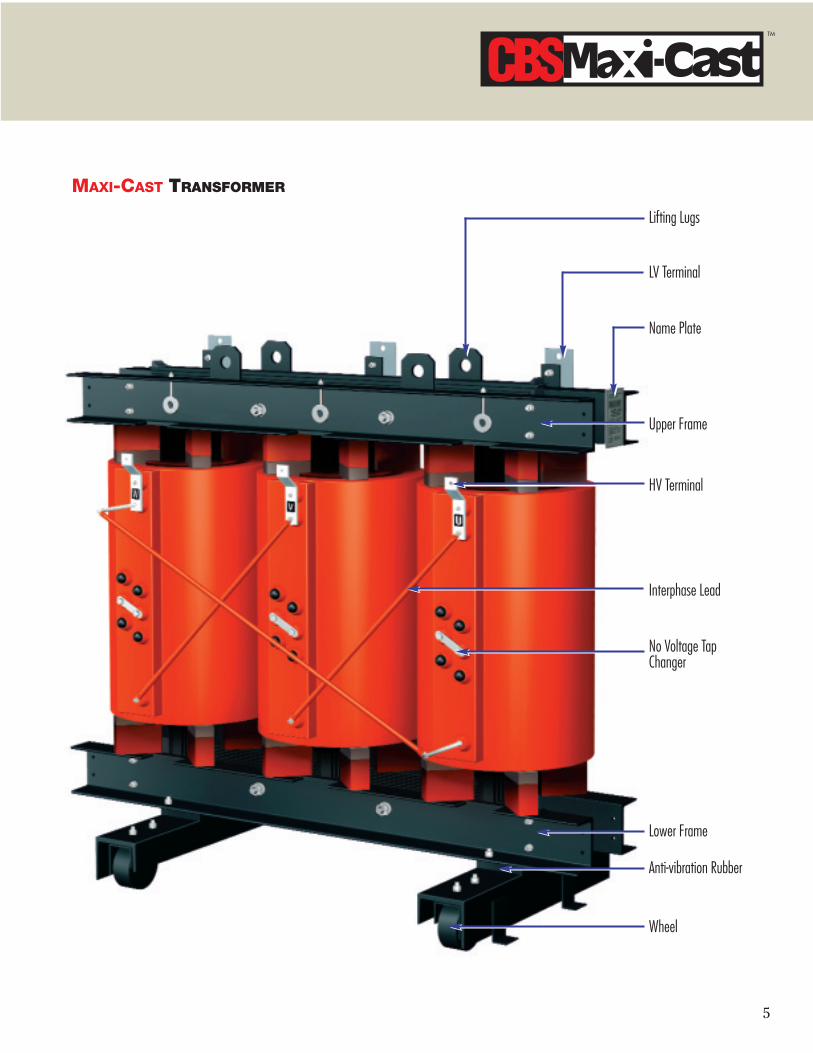
MAXI-CAST TRANSFORMER
Wheel
Lower Frame
Anti-vibration Rubber
No Voltage Tap Changer
Interphase Lead
HV Terminal
Upper Frame
Name Plate
LV Terminal
Lifting Lugs

6
FEATURES/CHARACTERISTICS
MOISTURE PROOF
The complete casting of HV and LV coilsunder vacuum prevents the penetration ofmoisture into the winding and the break-down by ionization. Therefore, it is suitablefor both storage and operation in adverseenvironments, including prolonged storagein up to 100% humidity and is capable ofbeing energized immediately after suchstorage without drying.
NO PARTIAL DISCHARGE
There is no possibility of partial dischargein MAXI-CAST transformers.
Each high voltage coil is individually testedfor partial discharge before assembly toensure a partial discharge-free operationunder all circumstances, and to guaranteethe life expectancy of the insulation system.
MAXI-CAST transformers are free of partialdischarge at least up to 1.2 times of therated voltage, and no visible corona at 2times the rated voltage.
IMPULSE VOLTAGE STRENGTH
MAXI-CAST transformers have impulselevels equal to liquid-immersedtransformers. The coils are very resistant toimpulse voltage. Impulse withstand levelsto 200kv are available because of carefuldesign and special structure. The impulsevoltage stress of the HV coil is evenlydistributed throughout the winding due to asuitable winding arrangement.
SHORT CIRCUIT RESISTANT
The coil construction provides the highestmechanical withstand capability. Thedynamic short circuit strength of a MAXI-CAST transformer is greatly superior to that of liquid-immersed or dry type transformers.
In the event of a maximum short circuit,MAXI-CAST transformers are notendangered mechanically, due to the denseglass fiber filling and the adhesion of epoxyresin to the conductors. In case of a shortcircuit, the conductors heat up much fasterthan the surrounding insulation.
Therefore only a strong glass fiberreinforced design, as found in cast resintransformers can prevent cracking of thecoils and failure.
THERMAL SHOCK RESISTANCE
Tensile and bending strength of glass fiber reinforced epoxy resin (used in theMAXI-CAST design) is appreciably higherthan that of quartz powder filled resin(used by mostly other manufacturers) hasthe disadvantage of becoming brittle andtending to crack when exposed to lowtemperature. Due to the completecombination of epoxy resin and glass fiber,even the worst temperature fluctuation willnot induce the cracking of the coils inMAXI-CAST transformers.
HIGH OVERLOAD CAPABILITY
Based on the high thermal time constantfactor of the windings, MAXI-CASTtransformers can be overloaded forconsiderably longer periods of time thanliquid immersed or dry type transformers.It has a greater capability to withstandsudden momentary high overloads such asmight be encountered in heavy traction orsevere duty industrial applications.
(CORONA TEST CIRCUIT)
7
TM
FEATURES/CHARACTERISTICS
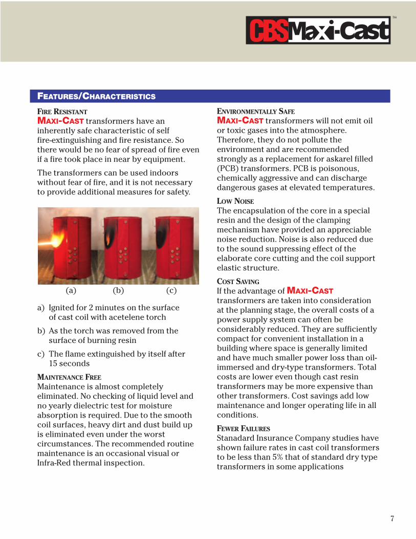
FIRE RESISTANT
MAXI-CAST transformers have aninherently safe characteristic of self fire-extinguishing and fire resistance. Sothere would be no fear of spread of fire evenif a fire took place in near by equipment.
The transformers can be used indoorswithout fear of fire, and it is not necessaryto provide additional measures for safety.
a) Ignited for 2 minutes on the surface of cast coil with acetelene torch
b) As the torch was removed from thesurface of burning resin
c) The flame extinguished by itself after 15 seconds
MAINTENANCE FREE
Maintenance is almost completelyeliminated. No checking of liquid level andno yearly dielectric test for moistureabsorption is required. Due to the smoothcoil surfaces, heavy dirt and dust build upis eliminated even under the worstcircumstances. The recommended routinemaintenance is an occasional visual orInfra-Red thermal inspection.
(a) (b) (c)
ENVIRONMENTALLY SAFE
MAXI-CAST transformers will not emit oilor toxic gases into the atmosphere.Therefore, they do not pollute theenvironment and are recommendedstrongly as a replacement for askarel filled(PCB) transformers. PCB is poisonous,chemically aggressive and can dischargedangerous gases at elevated temperatures.
LOW NOISE
The encapsulation of the core in a specialresin and the design of the clampingmechanism have provided an appreciablenoise reduction. Noise is also reduced dueto the sound suppressing effect of theelaborate core cutting and the coil supportelastic structure.
COST SAVING
If the advantage of MAXI-CASTtransformers are taken into considerationat the planning stage, the overall costs of apower supply system can often beconsiderably reduced. They are sufficientlycompact for convenient installation in abuilding where space is generally limitedand have much smaller power loss than oil-immersed and dry-type transformers. Totalcosts are lower even though cast resintransformers may be more expensive thanother transformers. Cost savings add lowmaintenance and longer operating life in allconditions.
FEWER FAILURES
Stanadard Insurance Company studies haveshown failure rates in cast coil transformersto be less than 5% that of standard dry typetransformers in some applications

8
MAXI-CAST TRANSFORMER SECTION
1
2
3
4
5
6
7
8
9
14
10 11
12
13
15
16
15A
17
18
19
24
20
21
22
25
HV Coil
LV Coil
1 Lifting Lugs2 LV Terminals3 HV Coil4 LV Coil Termination5 Core Bandage6 LV Coil7 Pulling Holes8 Lower Frame9 Core Yoke
10 Core Bolt Insulation11 Core Pressing Bolts12 Upper Frame13 Coil Clamp Adjustor14 Tap Link15 Resin Support Block15A Resilient Pad16 Core Leg17 Tie Bars
18 HV Terminal19 HV Taps20 Anti-Vibration Rubber21 Trolley Frame22 Bi-directional Wheel23 HV Conductors24 Air Ducts for Cooling25 LV Conductors

9
TM
CONSTRUCTION
MAXI-CAST transformers prides itself inthe ability to offer a wide variety of designsand configuations to satisfy most customerneeds. Computers and CAD/CAM systemsare used to quickly and accurately designand manufacture to meet specific customerrequirements.
CORE AND FRAME
The core is made of the highest quality,cold-rolled, grain-oriented, high siliconcontent steel and acurately cut on thelatest CNC machines.
Three legs of the core are arranged in asingle plane and interconnected with ayoke. The legs are arranged circularstructure multi-ply step-wise design, andare carefully interlaced with stepwiseepoxy arranged yokes. The core is miteredat a 45° angle and carefully stacked toobtain very low losses, exciting current andnoise. The core is insulated on both sidesof each lamination and protected againstcorrosion by a resin coating and groundedin accordance with required standards.
The frame consists of upper and lower steelchannels. It holds the core and coiltogether securely. The undercarriage isbolted to the bottom of the lower frame.Wheels enable the transformer to bemoved either length -wise or side -wise.Lifting lugs andgroundingterminals arefitted to the upperand lower framerespectively. Toprotect againstcorrosion, all steelparts are coatedwith epoxy paint.
LOW VOLTAGE AND HIGH VOLTAGE WINDING
High grade insulated copper wire is used inall winding construction.
Turns are arranged in multiple sections andlayers as dictated by design requirements.Cooling ducts are strategically placedwithin the windings to provide low thermaldrop through thin sections of insulation,and provide smooth and even surfaces foreffective convection or forced air cooling.The completed windings are placed in closetolerance with molds and cast under highvacuum conditions using a very lowviscosity epoxy resin. The resin penetratesand saturates all portions of the windings.After the molds are filled with epoxy resin,they are moved into carefully programmedovens where the epoxy resin is fully cured.
Finished coils contain smooth surfaces toenhance heat transfer to cooling air, andalso prevent dirt or dust build-up. Thecomplete saturation and penetration of theresin results in a winding free of partialdischarge, well above operating voltageconditions. Glass cloth and fiberglass matrender outstanding mechanical strengthproperties as well to the finished product.

10
CONSTRUCTION
NO-VOLTAGE TAP CHANGER
MAXI-CAST transformers are providedwith a re-connectable link tap changingdevice on the high voltage side of thetransformer. This can be operated with thetransformer de-energized only to changethe ratio of the transformer.
The device is sturdy in construction, andthe links are clearly identifiable as to thetap selected.
COOLING FANS
Forced cooling is a relatively simplemethod of increasing the capacity of castresin transformers. This is especiallyadvantageous for transformers which arehighly loaded only for a few hours a dayand then operated at a normal load for therest of the time. Fans are mounted on bothsides of the transformer base. Through theuse of cooling fans, a capacity increase of 30- 50% can be achieved with minimal efforts.It is also very effective at sites where theavailable space is limited and peak loadconditions are only needed on a limitedbasis.
TEMPERATURE MONITORING UNIT
The temperature monitoring controlsystem protects the coils againstoverheating due to increased ambienttemperature or overload, and permitsutilization of full transformer power at anyrequired load cycle without hazard to thetransformer.
This system consists of a protective relayand temperature sensors buried in theupper portion of the low voltage coils sothat the direct temperature measurementof the coils can be made. When thetemperature of the coils exceeds its setvalue, a control relay operates and closesthe contacts. This can activate an alarm orstart fans to cool the transformer.

11
TM
CONSTRUCTION
ENCLOSURE
MAXI-CAST transformers are normallysupplied without an enclosure (Core andCoil only), Additional protection may beoffered by an enclosure to protect againstsolid bodies and liquids.
*ENCLOSURE CBS1(Nema 1 indoor)
This has protection against solid bodiesgreater than 12mm diameter and haslouvered sheet steel or stainless steel walls.
The top panel is removable and the floor isopen to allow cables to be inserted easilythrough the floor.
*ENCLOSURE CBS2(Nema 3 outdoor)
This is similar to enclosure CBS1 but alsohas protection against rain and blowingwater up to 60 degrees from the vertical.
Because this enclosure is used in outdoorapplications it is equipped with a rain tightroof assembly and has hooded and filteredlouvered walls.
ASSEMBLY
HV and LV coils are arranged coaxially andclamped rigidly. The support structurebetween the core and coils is resilientpreventing the major part of vibrations andnoise caused by magnetostriction.
The noise level is dampened to a levelequivalent to that of oil-immersedtransformers.
QUALITY ASSURANCE
Quality assurance begins with a tightcontrol of incoming materials and iscontinuous throughout the various steps ofthe manufacturing process. Quality controlis carried through the testing of eachtransformer and ends only when thetransformer is installed and operating.
MAXI-CAST transformers are tested inaccordance with ANSI and IEC standardsprior to shipment, as noted below.Additionally, each high voltage coil isroutinely tested before assembly as ameans to verify the integrity of the epoxyimpregnation.
Notes:The MAXI-CAST factory has fully equippedlaboratory facilities for testing cast epoxyresin transformers. Tests are performed asnoted in the following table.
NO. ITEMS ROUTINE TYPE SPECIALTEST TEST TEST
1 Measurement of winding •insulation resistance
2 Measurement of turns ratio •3 Phase-relation test: •
Polarity, angular displacementand phase sequence
4 No-load loss and exciting current •5 Load loss and impedance •
voltage6 Applied potential dielectric test •7 Induced voltage dielectric test •8 Temperature rise test •9 Impulse voltage test •10 Measurement of sound level •11 Measurement of partial •
discharges12 Short-circuit test •13 Heat cycle test •
12
TECHNICAL DATA
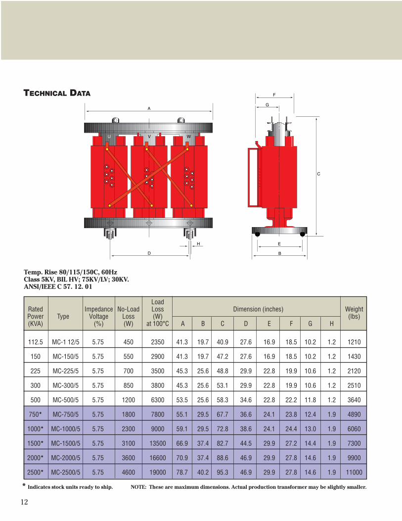
Temp. Rise 80/115/150C, 60HzClass 5KV, BIL HV; 75KV/LV; 30KV.ANSI/IEEE C 57. 12. 01
LoadRated Impedance No-Load Loss Dimension (inches) WeightPower Type Voltage Loss (W) (lbs)(KVA) (%) (W) at 100°C A B C D E F G H
112.5 MC-1 12/5 5.75 450 2350 41.3 19.7 40.9 27.6 16.9 18.5 10.2 1.2 1210
150 MC-150/5 5.75 550 2900 41.3 19.7 47.2 27.6 16.9 18.5 10.2 1.2 1430
225 MC-225/5 5.75 700 3500 45.3 25.6 48.8 29.9 22.8 19.9 10.6 1.2 2120
300 MC-300/5 5.75 850 3800 45.3 25.6 53.1 29.9 22.8 19.9 10.6 1.2 2510
500 MC-500/5 5.75 1200 6300 53.5 25.6 58.3 34.6 22.8 22.2 11.8 1.2 3640
750* MC-750/5 5.75 1800 7800 55.1 29.5 67.7 36.6 24.1 23.8 12.4 1.9 4890
1000* MC-1000/5 5.75 2300 9000 59.1 29.5 72.8 38.6 24.1 24.4 13.0 1.9 6060
1500* MC-1500/5 5.75 3100 13500 66.9 37.4 82.7 44.5 29.9 27.2 14.4 1.9 7300
2000* MC-2000/5 5.75 3600 16600 70.9 37.4 88.6 46.9 29.9 27.8 14.6 1.9 9900
2500* MC-2500/5 5.75 4600 19000 78.7 40.2 95.3 46.9 29.9 27.8 14.6 1.9 11000
* Indicates stock units ready to ship. NOTE: These are maximum dimensions. Actual production transformer may be slightly smaller.

13
TM
TECHNICAL DATA
Temp. Rise 80/115/150C, 60HzClass 15KV, BIL HV; 110KV/LV; 30KV.ANSI/IEEE C 57. 12. 01
LoadRated Impedance No-Load Loss Dimension (inches) WeightPower Type Voltage Loss (W) (lbs)(KVA) (%) (W) at 100°C A B C D E F G H
112.5 MC-1 12/15 5.75 520 2700 44.1 25.6 45.3 30.0 22.8 20.0 10.4 1.2 1370
150 MC-150/15 5.75 650 3200 41.1 25.6 51.6 30.0 22.8 20.0 10.4 1.2 1590
225 MC-225/15 5.75 850 3700 51.2 29.5 54.7 33.5 24.1 23.2 11.2 1.9 2360
300 MC-300/15 5.75 1000 4300 51.2 29.5 61.4 33.5 24.1 23.2 11.2 1.9 2820
500 MC-500/15 5.75 1550 7100 59.1 29.5 68.9 39.4 24.1 27.6 12.8 1.9 4270
750* MC-750/15 5.75 2100 8600 63.0 37.4 74.4 41.7 30.0 27.8 13.2 1.9 5580
1000* MC-1000/15 5.75 2750 9000 68.9 37.4 76.8 45.7 30.0 28.1 14.4 1.9 7120
1500* MC-1500/15 5.75 3500 12000 70.0 40.2 82.7 46.9 34.3 29.9 14.8 1.9 8300
2000* MC-2000/15 5.75 4600 16600 78.7 40.2 91.7 51.6 34.3 31.7 15.9 1.9 11660
2500* MC-2500/15 5.75 5200 19000 83.5 40.2 98.4 51.6 34.3 31.7 15.9 1.9 13400
TM
* Indicates stock units ready to ship. NOTE: These are maximum dimensions. Actual production transformer may be slightly smaller.

14
SPECIFICATION
SPECIFICATION DATA
MAXI-CAST transformers are normallyavailable with specification as follows:
Rated Voltage• HV coil: Up to 36KV• LV coil: 0.48-4.16 KV
* MAXI-CAST transformers with multiplehigh voltage connections can also besupplied.
Tap Range• Standard: ±2.5%, ±5%
* Other ratings are available by arrangement.
Power Capacity• Single phase. 20 - 2,000 KVA• Three phase: 50 - 10,000 KVA• Frequency: 50Hz, 60Hz• Typical % impedance voltage: 4-8% Connections• HV coil: Delta• LV coil: Wye with neutral point
* Other connections are available to meetrequirements.
Temperature ratings (according to ANSI C-57)• HV coil: Class F• LV coil: Class F• Max. ambient temperature: 40° C• Temperature rise limitation: 150° CTolerance (according to ANSI C-57)• Total losses: +10%• Component losses: +15%
(No-load and load losses)• No-load current: +30% • Impedance voltage: ±10%
(at rated current)• Voltage ratio: ±0.5% or 1/10 of measured
impedance voltage at rated current.
STANDARDS
MAXI-CAST transformers conform to therequirements of ANSI/IEEE C57-12.01 (1979)standards. However they can also meet therequirements of the following standards,upon request:• ANS IEC726 (1982)
General requirements for dry-typedistribution and power transformers
• BS-171 (1978)Power transformers
• CSA standard C9-M (1981)Dry-type transformer
• AS2374 (1982)Power transformer
• VDE 0532 (1982)* Transformers for rectifier applications
and other special purposes can besupplied according to the client'sspecification (Rapid Transit System, Airand Iron Core Reactors, PrecipitatorTransformers etc.)
ACCESSORIES
NORMALLY PROVIDED ACCESSORIES
• Terminal screws and links for HV taps• Nameplate• Ground wire clamping screw• Protective cap for HV taps• Lifting lugs• Danger labels• Installation manualOPTIONAL ACCESSORIES
• PTC thermistor & relay unit• Wheels• Dial-type thermometer• Anti-vibration pads• Enclosure• Anchor boltsSPECIAL ACCESSORIES
• Cooling fans and control relay
TM
GROUP CBS, INC.
WE PROVIDE
QUALITY
MAINTENANCE, REPAIR AND
SUPPLY SERVICES
WORLDWIDE
www.electrical911.com
www.groupcbs.com
Circuit Breaker Sales Co., Inc. World's largest inventory of low and medium voltage circuit breakers.Millions of parts in stock. Complete service, remanufacture and upgradecapabilities including building new or matching existing switchgear lineupfrom 480V to 34.5kV. Tel: 800-232-5809 www.circuitbreakersales.com
Arc Technology, Inc. Electrical contact retipping and replacement for oil switches, air switches,tap changers, regulators, circuit breakers, motor starters and reclosers. Tel: 253-735-0485 www.arc-technology.com
CBS Power Products, Inc. New alternative utility and industrial power products. Transformers, vacuum circuit breakers and other power apparatus. Tel: 972-250-2500 www.cbspowerproducts.com
Northwest Circuit Breakers, Inc. Serving the Pacific Northwest with shop or field service, repair, upgrade or replacement of power system apparatus. Tel: 253-735-0192 www.nwcircuitbreakers.com
Solid State Exchange & Repair, Inc. Service and support for all brands and types of solid state powerelectronics including circuit breaker trip devices, rating plugs, protective relays and more. Tel: 940-243-3731 www.solidstaterepair.com
Circuit Breaker Sales & Repair, Inc. Servicing the Gulf Coast with shop or field service, repair, upgrade or replacement of power system apparatus. Tel: 713-921-4545 www.cbsalesandrepair.com
Transformer Sales Co. Dry, cast coil and liquid filled transformers up to 34.5kV. Tel: 940-665-4484 www.transformersales.com
Instel Power Services, Inc. Serving the Southeast with onsite testing, maintenance and repairservices. Full NETA shop specializing in onsite maintenance and power quality monitoring. Tel: 864-288-0991 www.instelpower.com
Sentinel Power Services, Inc. Serving the Central U.S. with onsite testing, maintenance and repairservices for low and medium voltage substations, switchgear,transformers, circuit breakers and protective relays. Tel: 800-831-9550 www.sentinelpowerservices.com
Astro Controls, Inc. Sales and service for all types of industrial molded case circuit breakersand motor controls. Tel: 800-289-2757 www.astrocontrols.com
http://www.lgindustrialsystems.comP.O. Box 1557
Gainesville, Texas 76240 Tel: 940-665-6026
Fax: 940-665-4681 E-mail: [email protected]
P.O. Box 703766Dallas, Texas 75370Tel: 972-250-2500Fax: 972-250-2501
E-mail: [email protected]