Embed Size (px)
Citation preview

CPU CISC example:
Intel x86
Calcolatori Elettronici e Sistemi Operativix86: history
CPU Year Data
Bus
Max.
Mem.
Transistors Clock MHz Av. MIPS Level-1 Caches
8086 1978 16 1MB 29K 5-10 0.8
80286 1982 16 16MB 134K 8-12 2.7
80386 1985 32 4GB 275K 16-33 6
80486 1989 32 4GB 1.2M 25-100 20 8Kb
Pentium 1993 64 4GB 3.1M 60-233 100 8K Instr + 8K Data
Pentium
Pro
1995 64 64GB 5.5M
+15.5M
150-200 440 8K + 8K + Level2
Pentium II 1997 64 64GB 7M 266-450 466- 16K+16K + L2
Pentium III 1999 64 64GB 8.2M 500-1000 1000- 16K+16K + L2
Pentium 4 2001 64 64GB 42M 1300-2000 8K + L2
x86: history
� Intel introduced microprocessors in 1971
� 4-bit microprocessor 4004 (1971)
� 8-bit microprocessors� 8008 (1972)� 8080 (1974)� 8085 (1975)
� 16-bit processors� 8086 introduced in 1978
� 20-bit address bus, 16-bit data bus
� 8088 (1979)� a less expensive version of 8086� Uses 8-bit data bus
� Can address up to 4 segments of 64 KB
� Referred to as the real mode
first x86 CPU
x86: history
� 80186 (1982)
� A faster version of 8086
� 16-bit data bus and 20-bit address bus
� Improved instruction set
� 80286 (1982)
� 24-bit address bus
� 16 MB address space
� Enhanced with memory protection capabilities
� Introduced protected mode
� Segmentation in protected mode is different from the real mode
� Backwards compatible

x86: history
� 80386 (1985)
� First 32-bit processor
� 32-bit data bus and 32-bit address bus
� 4 GB address space
� Segmentation can be turned off (flat model)
� Introduced paging
� 80486 (1989)
� Improved version of 386
� Combined coprocessor functions for performing floating-point arithmetic
� Added parallel execution capability to instruction decode and execution
units
� Achieves scalar execution of 1 instruction/clock
� Later versions introduced energy savings for laptops
first 32-bit CPU
x86: history
� Pentium (1993)
� Similar to 486 but with 64-bit data bus
� Wider internal datapaths
� 128- and 256-bit wide
� Added second execution pipeline
� Superscalar performance
� Two instructions/clock
� Doubled on-chip L1 cache
� 8 KB data
� 8 KB instruction
� Added branch prediction
x86: history
� Pentium Pro (1995)
� Three-way superscalar
� 3 instructions/clock
� 36-bit address bus
� 64 GB address space
� Introduced dynamic execution
� Out-of-order execution
� Speculative execution
� In addition to the L1 cache
� Has 256 KB L2 cache
x86: history
� Pentium II (1997)
� Introduced multimedia (MMX) instructions
� Doubled on-chip L1 cache
� 16 KB data
� 16 KB instruction
� Introduced comprehensive power management features
� Sleep
� Deep sleep
� In addition to the L1 cache
� Has 256 KB L2 cache
� Pentium III, Pentium 4,...
� Pentium 4F (2005) first x86-64

IA-32: P6
� 3-ways superscalar, 12-stages pipelined
� branch prediction
� out-of-order execution
� speculative execution
� mode of operation
� real mode (emulates a 8086)
� protected mode (32-bit environment)
� system management mode
Example
� Core i7-3970X: Sandy Bridge-E (6 cores) 32 nm (2.27 billion transistors)
� Caches:� µ-ops cache: 1536 µ-ops per core� L1: 32 KB (I$) + 32 KB (D$) per core [8-way – line: 16-B]� L2: 256 KB per core [8-way – line: 64-B]� L3: 15 MB shared [16-way – line: 64-B]
� 3.5 GHz (memory bus: 800 MHz) - 150 W
� Pipeline: 19 stages� µ-op hit � 5 stages skipped
� 4 instruction decoders (instruction to µ-ops translators)� SIMD instructions
� MMX� SSE, SSE2, SSE3, SSE4
� AES instructions� AVX: Advanced Vector Extensions� EM64T: Extended Memory 64 technology� NX / XD / Execute disable bit� HT: Hyper-Threading technology (Hardware multithreading: factor 2)� Virtualization support
� VT-x: Virtualization technology� VT-d: Virtualization for directed I/O
� TBT: Turbo Boost technology� Enhanced SpeedStep technology
Operating modes
� Real-address mode
� Behaves as an 8086 (with a few extensions)
� Protected mode
� Native operating mode
� System management mode
� To handle power management and OEM variants
� Virtual-8086 mode
� To emulate an 8086 inside the protected mode
GP registers
Register Special use
� EAX: accumulator for operands and results data
� EBX: pointer to data
� ECX: counter for string and loop operations
� EDX: I/O pointer
� ESI: pointer to data; source pointer for string operations
� EDI: pointer to data (ES segment); destination ptr for string operations
� ESP: stack pointer
� EBP: pointer to data on the stack

8086: registers
Eight 16-bit
GP-Registers
SS
CS
DS
ES
FLAGS
16-bit Status-flags Register
IP
16-bit Instruction Pointer
R7
R0
Eight 80-bit
FP-Registers
CR
SR
TR
FP Control Registers
(16-bit)
AH AL AX
BH BL
CH CL
DH DL
BX
CX
DX
DI
SI
BP
SP
Four 16-bit
Segment Registers
8087
I-fetch: MEM[CS<<4 + IP]
D-fetch: MEM[DS<<4 + address] (other segment selectors can be forced)
mov AX, [BX+4]
mov CX, CS:[DX+4]
stack access: MEM[SS<<4 + SP]
POP AX
PUSH BX
IA-32: registers
EDX
EAX
EBX
ECX
ESP
EDI
ESI
EBP
Eight 32-bit
GP-Registers
SS
CS
DS
ES
FS
GS
Six 16-bit
Segment Registers
EFLAGS
32-bit Status-flags Register
EIP
32-bit Instruction Pointer
R7
R0
Eight 80-bit
FP-Registers
CR
SR
TR
FP Control Registers
(16-bit)
IPR 48 bits
48 bitsDPR
OPR
MMX3
MMX0
MMX1
MMX2
MMX7
MMX4
MMX5
MMX6
Eight 64-bit
MMX-Registers
XMM3
XMM0
XMM1
XMM2
XMM7
XMM4
XMM5
XMM6
Eight 128-bit XMM-Registers11 bits
AH AL AX
BH BL
CH CL
DH DL
BX
CX
DX
DI
SI
BP
SP
Status-flags Register (EFLAGS)
31 30 29 28 27 26 25 20 19 16 15 10 9 8 7 6 5 4 024 23 22 21 18 17 14 13 12 11 3 2 1
0 ID VIP VIF AC VM RF 0 NT IOPL IF TF 0 0 1OF DF SF ZF AF PF CF
User flags:
OF: Overflow Flag
DF: Direction Flag (set by sw to control string operations: MOVS, CMPS, SCAS, LODS, STOS)
SF: Sign Flag
ZF: Zero Flag
AF: Auxiliary Carry Flag (carry generated from bit 3; used for BCD operations)
PF: Parity Flag (least significant bit of the result)
CF: Carry Flag
Status-flags Register (EFLAGS)
31 30 29 28 27 26 25 20 19 16 15 10 9 8 7 6 5 4 024 23 22 21 18 17 14 13 12 11 3 2 1
0 0 OF DF SF ZF 0 AF 0 PF 1 CFID VIP VIF AC VM RF NT IOPL IF TF
System flags:
ID: ID Flag (if writable, CPUID instruction is supported)
VIP: Virtual Interrupt Pending (to record that a virtual interrupt is pending: only written by sw)
VIF: Virtual Interrupt Flag (1: virtual interrupt enabled)
AC: Alignment Check (1: alignment check exceptions enabled)
VM: Virtual-8086 Mode (set to enable virtual-8086 mode)
RF: Resume Flag (1: debug exceptions disabled, to allow resuming after a breakpoint)
NT: Nested Task (1: a CALL, an interrupt, or an exception caused a task switch)
IOPL: I/O Privilege Level (max privilege level required for accessing IO address space)
IF: Interrupt Enable Flag (1: interrupt enabled)
TF: Trap Flag (1: single-step mode for debugging)

IA-32: other registers
� Control registers
� CR0, CR1, CR2, CR3, CR4� CR0 also specifies the if the protected mode is active
� 3 functioning modes (0-2: privileged modes – 3 user mode)
� Memory management registers� GDTR, IDTR, LDTR
� for protected mode memory management
� Memory type range registers (MTRRs)
� Debug registers
� DR0, ..., DR7
� Machine specific registers (MSRs)
� Machine check registers
� Performance monitoring counters
Memory model
� Segmented and paged memory
� Segment and offset: logical address
� Logical address � Linear address
� Segment Descriptor Table
� Linear address � Physical address
� Page Table
8086 memory model
� 16 bit processor
� 20 bit address bus
� max addressable memory: 1MB
� 16 bit data bus
� 8 bit for 808816 bit address
16 bit segment register <<4
+
20-bit
base address
20-bit address (physical)
8086 memory model
Add
ress
spa
ce
0
220-1
seg base
offset
20 bit
16 bit
216 B = 64 KB
seg. register
16 bit
<<4
� only address translation
� no protection

IA-32: memory models
� Segmented memory model
� Flat memory model
� 32 bit linear address space
� Real-address memory model
� for 8086 emulation
IA-32: segmented memory model
seg selector offset16 bit32 bit
accessbase address
limit
Segment Descriptor Table
(Global or Local)
seg register
segment descriptor
13
uses bits (15:3)
+ Linear address
GDTR or LDTR
32 bit
linear address
segment_selector : offset � logical address
IA-32: segmented memory model
0
232-1
CS
IP
16 bit
32 bit
code segment
accessbase address
limit
accessbase address
limit
data segment
DS
16 bit
address32 bit
Linear address space
Segment Descriptor Table13
13
IA-32: flat memory model
0
232-1
Linear address space
Segment Descriptor Table
16 bit
13
13
CS
16 bit
DS
16 bit
ES
16 bit
FS
16 bit
GS
16 bit
SS
13
13
13
13
accessbase address
limit

IA-32: segment registers
Index TI RPL
15 3 2 1 0
TI: 0 GDT - 1 LDT
RPL: requested privilege level
Segment selector Access information, Limit, Base address
Segment selector Access information, Limit, Base address
Segment selector Access information, Limit, Base address
Segment selector Access information, Limit, Base address
Segment selector Access information, Limit, Base address
Segment selector Access information, Limit, Base address
CS
DS
ES
FS
GS
SS
Segment selector
Segment registers
Visible portion Hidden portion (shadow register)
2-bits: current privilege level (CPL)
IA-32: Segment Descriptors
63 62 61 60 59 78 57 56 55 54 53 52 51 50 49 48 47 46 45 44 43 42 41 40 39 38 37 36 35 34 33 32
BASE 31:24 GD
/
BL
A
V
LLIMIT 19:16 P DPL S TYPE BASE 23:16
31 30 29 28 27 26 25 24 23 22 21 20 19 18 17 16 15 14 13 12 11 10 9 8 7 6 5 4 3 2 1 0
BASE 15:0 LIMIT 15:0
L: 64-bit code segment
AVL: available for system software
BASE: base address
D/B: code segment: Default operation size (16 (0) or 32 (1) bit)
data segment: address size for stack access (16 bit (0) or 32 bit (1 Big))
DPL: descriptor privilege level
G: granularity (byte (0) or page (1))
LIMIT: segment size (bytes if G=0, 4KB pages if G=1)
P: present
S: type (0=system; 1=code or data)
TYPE: segment type (data, code, stack, read/write, ...)
IA-32: Segment Descriptors
0 E W A
� Type field
Data segment descriptorE: Expansion direction
0: valid addresses from 0 to Limit
1: valid addresses from Limit to maximum (for stacks)
W: Writable
A: Accessed
1 C R A Code segment descriptorC: Conforming
R: Readable
A: Accessed
IA-32: Segment Descriptors
� System descriptors
� System segment descriptors
� LDT: Local Descriptor-Table segment descriptor
� TSS: Task-state segment descriptor
� Function pointers
� Call-gate descriptor
� Interrupt-gate descriptor
� Trap-gate descriptor
� Indirect (protected) reference to a TSS
� Task-gate descriptor

IA-32: Segment Tables
seg. descriptor
LDT
TSS
seg. descriptor
Global
Descriptor
Table
Global
Code/Data
Segment
Task
State
Struct
Local
Code/Data
Segment
Local
Descriptor
Table
GDTR
LDTR
TR
Task Gate
IA-32: Segment Tables
Task Gate
Trap GateInterrupt
Descriptor
Table
IDTR
Interrupt Gate
to a TSS selector in GDT or LDT
“pointer” and access rights
“pointer” and access rights
63 62 61 60 59 78 57 56 55 54 53 52 51 50 49 48 47 46 45 44 43 42 41 40 39 38 37 36 35 34 33 32
Offset 31:16 P DPL 0 D 1 1 0type
0 0 0 reserved
31 30 29 28 27 26 25 24 23 22 21 20 19 18 17 16 15 14 13 12 11 10 9 8 7 6 5 4 3 2 1 0
Segment selector Offset 15:0
63 62 61 60 59 78 57 56 55 54 53 52 51 50 49 48 47 46 45 44 43 42 41 40 39 38 37 36 35 34 33 32
Offset 31:16 P DPL 0 D 1 1 1type
0 0 0 reserved
31 30 29 28 27 26 25 24 23 22 21 20 19 18 17 16 15 14 13 12 11 10 9 8 7 6 5 4 3 2 1 0
Segment selector Offset 15:0
Interrupt Gate
Trap Gate
IA-32: Segment Tables
� First entry in GDT is not used
� accessing the #0 segment � General Protection error
� GDT descriptors
� Code/Data segment descriptors
� System descriptors
� LDT
� TSS
� Task/Call/Interrupt/Trap gates
IA-32: Segment Tables
� LDT descriptors
� Code/Data segment descriptors
� System descriptors
� Task/Call/Interrupt/Trap gates
� IDT descriptors
� System descriptors
� Task/Interrupt/Trap gates

Segment Descriptor Tables location
Linear Base Address Table Limit
47 16 15 0
Segment Selector Linear Base Address Table Limit
47 16 15 015 0
GDTR and IDTR format
LDTR and TR format
LDTR and TR are reloaded whenever a task switch happens
GDTR: Global Descriptor Table Register
IDTR: Interrupt Descriptor Table Register
LDTR: Local Descriptor Table Register
TR: Task Register
IDT: table of gate descriptors (“access entries”
for interrupt management)
TR: info about current TSS (task state segment)
TSS: data structure with task informations
Paging
� Enabled with control bits
� CR0.PG=1 and CR0.PE=1
� 3 paging modes
� 32-bit paging
� PAE paging
� IA-32e paging
Paging
� Enabled with control bits
� CR0.PG=1 and CR0.PE=1
� 3 paging modes
� 32-bit paging
� Linear address: 32 bits
� Physical address: 32 bits
� Up to 40 bits when 4 MB pages are used and PSE-36 is supported
� Page size: 4 KB or 4 MB PSE-36: page-size extensions with
40-bit physical-address extension.
Paging
� Enabled with control bits
� CR0.PG=1 and CR0.PE=1
� 3 paging modes
� PAE paging
� Linear address: 32 bits
� Physical address: up to 52 bits
� Page size: 4 KB or 2 MB

Paging
� Enabled with control bits
� CR0.PG=1 and CR0.PE=1
� 3 paging modes
� IA-32e paging
� Linear address: 48 bits
� Physical address: up to 52 bits
� Page size: 4 KB, 2 MB, or 1 GB
Paging
Page Directory address ignored
PWT
ignored
PCD
31 12 11 5 4 3 2 0
Control Register 3 (CR3) format
PCD: Page Cache Disable
PWT: Page Write Through
Caching attributes:
if PAT is not supported: use bits PCD and PWT in CR3
if PAT is supported: use bits PCD and PWT in PDEs and PTEs
PAT: Page Attribute TablePentium III and later
32-bit paging
PDE
PTE
Table address (CR3)
Page Directory
Page Table
31 12 11 0
12
1010
20
Physical address
20
00
2
Linear address
2
00
Physical address of
page directory entry
Physical address of
page table entry
20
2122
32-bit paging
PDE
Table address (CR3)
Page Directory
31 0
20
10
Physical address
20
Linear address
2
00
Physical address of
page directory entry
20
2122
Protection levels
Level 0
Level 1
Level 2
Level 3
Applications
Operating System Services
Operating System Kernel
Protection Rings
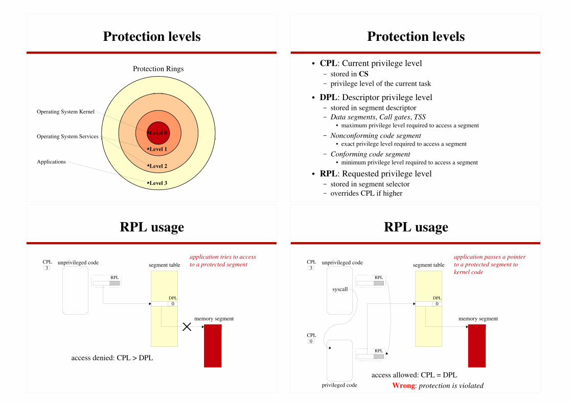
Protection levels
� CPL: Current privilege level� stored in CS
� privilege level of the current task
� DPL: Descriptor privilege level� stored in segment descriptor� Data segments, Call gates, TSS
� maximum privilege level required to access a segment
� Nonconforming code segment� exact privilege level required to access a segment
� Conforming code segment� minimum privilege level required to access a segment
� RPL: Requested privilege level� stored in segment selector� overrides CPL if higher
RPL usage
segment table
memory segment
0
3
CPL
DPL
unprivileged code
RPL
access denied: CPL > DPL
application tries to access
to a protected segment
RPL usage
segment table
memory segment
0
3
CPL
DPL
unprivileged code
RPL
0
CPL
privileged code
RPL
syscall
access allowed: CPL = DPL
Wrong: protection is violated
application passes a pointer
to a protected segment to
kernel code

RPL usage
segment table
memory segment
0
3
CPL
DPL
unprivileged code
0RPL
0
CPL
privileged code
3RPL
syscall
access denied: RPL > DPL
application passes a pointer
to a protected segment to
kernel code
but
operating system adjusts RPL to
match the caller privilege level
Exception Handling
� Exceptions
� Interrupts
� External interrupts
� Maskable interrupts
� APIC (Advanced Programmable Interrupt Controller) receives
interrupts (signals or messages) and maps them to interrupt
vectors (integer 0-255)
� NMI
� NMI pin or APIC NMI message
� Software-generated interrupts
� Instruction: INT x (x: integer 0-255)
� Actually a software exception
two bytes instruction:
INT n: 0xCD n
Exception Handling
� Exceptions
� Exceptions
� Program-Error Exceptions
� Faults:
� task can be restarted after exception handling� return address: faulting instruction
� Traps
� task can be restarted after exception handling� return address: instruction that follows the trapping one
� Aborts
� precise informations missing� severe errors (hw errors, wrong values in system tables, ...)� program resuming not possible
Exception Handling
� Exceptions
� Exceptions
� Software-Generated Exceptions
� Instructions: BOUND, INTO, INT3
� Machine-Check Exceptions
� Internal machine error, Bus error, Implementation dependent
checks
single byte instructions:
INTO: 0xCE
INT3: 0xCC

Exception Handling
IDTIDTR
Interrupt or Trap
Gate
GDT or LDT
Code segment (conforming)
Exception
procedure
Segment descriptor
+
0
255
i
CPL
Exception procedure is executed at the current
privilege level
DPL of gate is checked only for INT, INT3, or INTO
instructions
Exception Handling
IDTIDTR
Interrupt or Trap
Gate
GDT or LDT
Code segment (nonconforming)
Exception
procedure
Segment descriptor
+
0
255
i
CPLDPL
Exception procedure is executed at the privilege
level indicated in the segment descriptor
(with a stack switch if CPLold
> CPLnew
)
DPL of gate is checked only for INT, INT3, or INTO
instructions
Exception Handling
IDTIDTR
Task Gate
GDT or LDT
Task State Struct
TSS descriptor
0
255
i
Exception causes a task switch
DPL of gate is checked only for INT, INT3, or INTO
instructions
Exception Handling
� Software generated interrupts/exceptions
� INT n
� push flags and return address on stack� return address: instruction following "INT n"
� jump to interrupt vector n (use entry n of IDT)
� INT3
� similar to INT n� jump to interrupt vector 3
� INTO
� similar to INT n� generate exception if EFLAGS.OF=1� jump to interrupt vector 4

Exception Handling
� External interrupts
� Maskable interrupts
� APIC maps interrupt to interrupt vector x� push flags and return address on stack� return address: instruction following the interrupted one
� interrupted instruction is completed
� jump to interrupt vector x (use entry x of IDT)
� HW should use vectors 32-255
� NMI
� similar to maskable interrupts� use interrupt vector 2
Exception Handling
� Faults
� faulting instruction is aborted
� push flags and return address on stack� return address: faulting instruction
� Divide Error
� a DIV or IDIV instruction attempted to divide by 0
� jump to interrupt vector 0
� Debug Exception
� HW breakpoint on I-fetch
� jump to interrupt vector 1
Exception Handling
� Faults
� BOUND
� a BOUND instruction revealed a index out of array bounds
� jump to interrupt vector 5
� Invalid Opcode
� invalid instruction or operand
� jump to interrupt vector 6
� Device not available
� access to x87 or SSE/SSE2/SSE3 unit while not ready
� jump to interrupt vector 7
Exception Handling
� Faults
� Invalid TSS
� push an error code on stack (segment selector index)
� jump to interrupt vector 10
� Segment not present
� push an error code on stack (segment selector index)
� jump to interrupt vector 11
� Stack fault
� push an error code on stack (segment selector index or 0)
� jump to interrupt vector 12

Exception Handling
� Faults
� General protection
� push an error code on stack (segment selector index or 0)
� jump to interrupt vector 13
� Page fault
� push an error code and the faulting address on stack
� jump to interrupt vector 14
� x87 floating point error
� x87 stack overflow or IEEE-754 trap
� jump to interrupt vector 16
Exception Handling
� Faults
� Alignment check
� alignment check enabled and unaligned memory reference
� push an error code (0) on stack
� jump to interrupt vector 17
� SIMD floating point error
� Invalid operation
� Divide-by-zero, Denormal operand, Numeric overflow,
Numeric underflow, Inexact result
� jump to interrupt vector 19
Exception Handling
� Traps
� Trapping instruction is executed
� Push flags and return address on stack
� return address: instruction that follows the trap
� Debug Exception
� HW breakpoint on memory or IO read or write
� Single step debugging enabled
� Task switch debug enabled
� jump to interrupt vector 1
Exception Handling
� Traps
� Breakpoint Exception
� an INT3 instruction is executed
� jump to interrupt vector 3
� Overflow Exception
� an INTO instruction is executed and EFLAGS.OF=1
� jump to interrupt vector 4

Exception Handling
� Aborts
� Push flags and return address on stack
� return address: undefined
� Double Fault Exception
� An exception occurred inside an exception handler and
serial exception management is not feasible� e.g., page fault when handling a page fault
� push 0 (error code) on stack
� jump to interrupt vector 8
� Machine Check Exception
� jump to interrupt vector 18
IA-32: data types
� Integer
� byte
� word (16-bit)
� dword (32-bit) (double word)
� qword (64-bit) (quad word)
� dqword (128-bit) (double quad word)
� BCD
� Floating point
� single precision (32-bit: 1+8+23+1)
� double precision (64-bit: 1+11+52+1)
� double extended precision (80-bit: 1+15+64)
IA-32: memory addressing
EAX
EBX
ECX
EDX
ESP
EBP
ESI
EDI
EAX
EBX
ECX
EDX
ESP
EBP
ESI
EDI
1
2
4
8
*
none
8-bit
16-bit
32-bit
+ ( ) +
base index scale displacement
address =
e.g.: MOV EAX, [EBX+4*EDI+0xA000]
IA-32: instruction format
lock and repeat
segment override
operand size
address size
32-bit addressing formats with the mod and R/M fields
modreg/
opcode7 6 5 4 3 2 1 0
Scale Index
7 6 5 4 3 2 1 0
R/M Base
mod
R/M 00 01 10 11
000 [EAX] [EAX]+ disp8 [EAX]+ disp32 EAX/AX/AL/MM0/XMM0
001 [ECX] [ECX]+ disp8 [ECX]+ disp32 ECX/CX/CL/MM/XMM1
010 [EDX] [EDX]+ disp8 [EDX]+ disp32 EDX/DX/DL/MM2/XMM2
011 [EBX] [EBX]+ disp8 [EBX]+ disp32 EBX/BX/BL/MM3/XMM3
100 [--][--]+ disp8 [--][--]+ disp32 ESP/SP/AH/MM4/XMM4
101 disp32 [EBP]+ disp8 [EBP]+ disp32 EBP/BP/CH/MM5/XMM5
110 [ESI] [ESI]+ disp8 [ESI]+ disp32 ESI/SI/DH/MM6/XMM6
111 [EDI] [EDI]+ disp8 [EDI]+ disp32 EDI/DI/BH/MM7/XMM7
[--][--] SIB
reg/opcode: 2nd operand (if any)
000: EAX/AX/AL/MM0/XMM0
001: ECX/CX/CL/MM/XMM1
010: EDX/DX/DL/MM2/XMM2
011: EBX/BX/BL/MM3/XMM3
100: ESP/SP/AH/MM4/XMM4
101: EBP/BP/CH/MM5/XMM5
110: ESI/SI/DH/MM6/XMM6
111: EDI/DI/BH/MM7/XMM7
prefix
0-4 1-3 0-1 0-1 0-4 0-4
opcode mode SIB displacement immediate

IA-32: instruction format
lock and repeat
segment override
operand size
address size
mod
R/M 00 01 10 11
000 [BX+SI] [BX+SI] + disp8 [BX+SI] + disp16 EAX/AX/AL/MM0/XMM0
001 [BX+DI] [BX+DI] + disp8 [BX+DI] + disp16 ECX/CX/CL/MM/XMM1
010 [BP+SI] [BP+SI] + disp8 [BP+SI] + disp16 EDX/DX/DL/MM2/XMM2
011 [BP+DI] [BP+DI] + disp8 [BP+DI] + disp16 EBX/BX/BL/MM3/XMM3
100 [SI] [SI] + disp8 [SI] + disp16 ESP/SP/AH/MM4/XMM4
101 [DI] [DI] + disp8 [DI] + disp16 EBP/BP/CH/MM5/XMM5
110 disp16 [BP] + disp8 [BP] + disp16 ESI/SI/DH/MM6/XMM6
111 [BX] [BX] + disp8 [BX] + disp16 EDI/DI/BH/MM7/XMM7
16-bit addressing formats with the mod and R/M fields
reg/opcode: 2nd operand (if any)
000: EAX/AX/AL/MM0/XMM0
001: ECX/CX/CL/MM/XMM1
010: EDX/DX/DL/MM2/XMM2
011: EBX/BX/BL/MM3/XMM3
100: ESP/SP/AH/MM4/XMM4
101: EBP/BP/CH/MM5/XMM5
110: ESI/SI/DH/MM6/XMM6
111: EDI/DI/BH/MM7/XMM7
modreg/
opcode7 6 5 4 3 2 1 0
Scale Index
7 6 5 4 3 2 1 0
R/M Base
prefix
0-4 1-3 0-1 0-1 0-4 0-4
opcode mode SIB displacement immediate
IA-32: instruction set
� General-purpose instructions� Basic data movement, arithmetic, logic, program flow, and string operations� Operate on data contained in memory, in the GP registers (EAX, EBX, ECX,
EDX, EDI, ESI, EBP, and ESP) and in the EFLAGS register
� FPU instructions� FP and BCD operations
� SIMD extensions� MMX instructions
� operate on packed byte, word, doubleword, or quadword integer operands in memory,
MMX registers, and/or in GP registers.
� SSE instructions� operate on packed and scalar single-precision floating-point values located in XMM
registers and/or memory.
� SSE2 instructions� operate on packed double-precision floating-point operands and on packed byte, word,
doubleword, and quadword operands located in the XMM registers.
� SSE3 instructions
IA-32: instruction set
� FPU and SIMD state management instructions� System instructions
� processor's functions needed to support operating systems and protection
� 64-bit mode instructions
IA-32:
General-purpose instructions� Data Transfer Instructions
MOV Move data between general-purpose registers; move data between memory and general-purpose or
segment registers; move immediates to general-purpose registers
CMOVE/CMOVZ Conditional move if equal/Conditional move if zero
CMOVNE/CMOVNZ Conditional move if not equal/Conditional move if not zero
CMOVA/CMOVNBE Conditional move if above/Conditional move if not below or equal
CMOVAE/CMOVNB Conditional move if above or equal/Conditional move if not below
CMOVB/CMOVNAE Conditional move if below/Conditional move if not above or equal
CMOVBE/CMOVNA Conditional move if below or equal/Conditional move if not above
CMOVG/CMOVNLE Conditional move if greater/Conditional move if not less or
CMOVGE/CMOVNL Conditional move if greater or equal/Conditional move if not less
CMOVL/CMOVNGE Conditional move if less/Conditional move if not greater or equal
CMOVLE/CMOVNG Conditional move if less or equal/Conditional move if not greater
CMOVC Conditional move if carry
CMOVNC Conditional move if not carry
CMOVO Conditional move if overflow
CMOVNO Conditional move if not overflow
CMOVS Conditional move if sign (negative)
CMOVNS Conditional move if not sign (non-negative)
CMOVP/CMOVPE Conditional move if parity/Conditional move if parity even
CMOVNP/CMOVPO Conditional move if not parity/Conditional move if parity odd

IA-32:
General-purpose instructions� Data Transfer Instructions
XCHG Exchange
BSWAP Byte swap
XADD Exchange and add
CMPXCHG Compare and exchange
CMPXCHG8B Compare and exchange 8 bytes
PUSH Push onto stack
POP Pop off of stack
PUSHA/PUSHAD Push general-purpose registers onto stack
POPA/POPAD Pop general-purpose registers from stack
CWD/CDQ Convert word to doubleword/Convert doubleword to quadword
CBW/CWDE Convert byte to word/Convert word to doubleword in EAX register
MOVSX Move and sign extend
MOVZX Move and zero extend
IA-32:
General-purpose instructions� Binary Arithmetic Instructions
ADD Integer add
ADC Add with carry
SUB Subtract
SBB Subtract with borrow
IMUL Signed multiply
MUL Unsigned multiply
IDIV Signed divide
DIV Unsigned divide
INC Increment
DEC Decrement
NEG Negate
CMP Compare
IA-32:
General-purpose instructions� Decimal Arithmetic Instructions
DAA Decimal adjust after addition
DAS Decimal adjust after subtraction
AAA ASCII adjust after addition
AAS ASCII adjust after subtraction
AAM ASCII adjust after multiplication
AAD ASCII adjust before division
� Logical Instructions
AND Perform bitwise logical AND
OR Perform bitwise logical OR
XOR Perform bitwise logical exclusive OR
NOT Perform bitwise logical
IA-32:
General-purpose instructions� Shift and Rotate Instructions
SAR Shift arithmetic right
SHR Shift logical right
SAL/SHL Shift arithmetic left/Shift logical left
SHRD Shift right double
SHLD Shift left double
ROR Rotate right
ROL Rotate left
RCR Rotate through carry right
RCL Rotate through carry left

IA-32:
General-purpose instructions� Bit and Byte Instructions
BT Bit test
BTS Bit test and set
BTR Bit test and reset
BTC Bit test and complement
BSF Bit scan forward
BSR Bit scan reverse
SETE/SETZ Set byte if equal/Set byte if zero
SETNE/SETNZ Set byte if not equal/Set byte if not zero
SETA/SETNBE Set byte if above/Set byte if not below or equal
SETAE/SETNB/SETNC Set byte if above or equal/Set byte if not below/Set byte if not carry
SETB/SETNAE/SETC Set byte if below/Set byte if not above or equal/Set byte if carry
SETBE/SETNA Set byte if below or equal/Set byte if not above
SETG/SETNLE Set byte if greater/Set byte if not less or equal
SETGE/SETNL Set byte if greater or equal/Set byte if not
SETL/SETNGE Set byte if less/Set byte if not greater or equal
SETLE/SETNG Set byte if less or equal/Set byte if not greater
IA-32:
General-purpose instructions� Bit and Byte Instructions
SETS Set byte if sign (negative)
SETNS Set byte if not sign (non-negative)
SETO Set byte if overflow
SETNO Set byte if not overflow
SETPE/SETP Set byte if parity even/Set byte if parity
SETPO/ SETNP Set byte if parity odd/Set byte if not parity
TEST Logical compare
IA-32:
General-purpose instructions� Control Transfer Instructions
JMP Jump
JE/JZ Jump if equal/Jump if zero
JNE/JNZ Jump if not equal/Jump if not zero
JA/JNBE Jump if above/Jump if not below or equal
JAE/JNB Jump if above or equal/Jump if not below
JB/JNAE Jump if below/Jump if not above or equal
JBE/JNA Jump if below or equal/Jump if not above
JG/JNLE Jump if greater/Jump if not less or equal
JGE/JNL Jump if greater or equal/Jump if not less
JL/JNGE Jump if less/Jump if not greater or equal
JLE/JNG Jump if less or equal/Jump if not greater
JC Jump if carry
JNC Jump if not carry
JO Jump if overflow
JNO Jump if not overflow
IA-32:
General-purpose instructions� Control Transfer Instructions
JS Jump if sign (negative)
JNS Jump if not sign (non-negative)
JPO/JNP Jump if parity odd/Jump if not
JPE/JP Jump if parity even/Jump if parity
JCXZ/JECXZ Jump register CX zero/Jump register ECX zero
LOOP Loop with ECX counter
LOOPZ/LOOPE Loop with ECX and zero/Loop with ECX and equal
LOOPNZ/LOOPNE Loop with ECX and not zero/Loop with ECX and not equal
CALL Call procedure
RET Return
IRET Return from interrupt
INT Software interrupt
INTO Interrupt on overflow
BOUND Detect value out of range
ENTER High-level procedure entry
LEAVE High-level procedure exit

IA-32:
General-purpose instructions� String Instructions
MOVS/MOVSB Move string/Move byte string
MOVS/MOVSW Move string/Move word string
MOVS/MOVSD Move string/Move doubleword string
CMPS/CMPSB Compare string/Compare byte string
CMPS/CMPSW Compare string/Compare word string
CMPS/CMPSD Compare string/Compare doubleword string
SCAS/SCASB Scan string/Scan byte string
SCAS/SCASW Scan string/Scan word string
SCAS/SCASD Scan string/Scan doubleword string
LODS/LODSB Load string/Load byte string
LODS/LODSW Load string/Load word string
LODS/LODSD Load string/Load doubleword string
STOS/STOSB Store string/Store byte string
STOS/STOSW Store string/Store word
STOS/STOSD Store string/Store doubleword string
REP Repeat while ECX not zero
REPE/REPZ Repeat while equal/Repeat while zero
REPNE/REPNZ Repeat while not equal/Repeat while not zero
IA-32:
General-purpose instructions� I/O Instructions
IN Read from a port
OUT Write to a port
INS/INSB Input string from port/Input byte string from port
INS/INSW Input string from port/Input word string from port
INS/INSD Input string from port/Input doubleword string from port
OUTS/OUTSB Output string to port/Output byte string to port
OUTS/OUTSW Output string to port/Output word string to port
OUTS/OUTSD Output string to port/Output doubleword string to port
� Segment Register Instructions
LDS Load far pointer using DS
LES Load far pointer using ES
LFS Load far pointer using FS
LGS Load far pointer using GS
LSS Load far pointer using SS
IA-32:
General-purpose instructions� Flag Control (EFLAG) Instructions
STC Set carry flag
CLC Clear the carry flag
CMC Complement the carry flag
CLD Clear the direction flag
STD Set direction flag
LAHF Load flags into AH
SAHF Store AH register into flags
PUSHF/PUSHFD Push EFLAGS onto stack
POPF/POPFD Pop EFLAGS from stack
STI Set interrupt flag
CLI Clear the interrupt flag
� Miscellaneous Instructions
LEA Load effective address
NOP No operation
UD2 Undefined instruction
XLAT/XLATB Table lookup translation
CPUID Processor Identification
IA-32:
System instructionsLGDT Load global descriptor table (GDT) register
SGDT Store global descriptor table (GDT) register
LLDT Load local descriptor table (LDT) register
SLDT Store local descriptor table (LDT) register
LTR Load task register
STR Store task register
LIDT Load interrupt descriptor table (IDT) register
SIDT Store interrupt descriptor table (IDT) register
MOV Load and store control registers
LMSW Load machine status
SMSW Store machine status word
CLTS Clear the task-switched flag
ARPL Adjust requested privilege level
LAR Load access rights
LSL Load segment limit
VERR Verify segment for reading
VERW Verify segment for writing
MOV Load and store debug registers
INVD Invalidate cache, no writeback
WBINVD Invalidate cache, with writeback

IA-32:
System instructionsINVLPG Invalidate TLB Entry
LOCK (prefix) Lock Bus
HLT Halt processor
RSM Return from system management mode (SMM)
RDMSR Read model-specific register
WRMSR Write model-specific register
RDPMC Read performance monitoring counters
RDTSC Read time stamp counter
SYSENTER Fast System Call, transfers to a flat protected mode kernel at CPL = 0
SYSEXIT Fast System Call, transfers to a flat protected mode kernel at CPL = 3
IA-32: info
� IA-32 Intel Architecture Software Developer's Manual
� Volume 1: Basic Architecture
� Volume 2A: Instruction Set Reference, A-M
� Volume 2B: Instruction Set Reference, N-Z
� Volume 3: System Programming Guide