Embed Size (px)
Citation preview
8/11/21 EC 210315006074 Rev A Part No. 93103139 Page 1
AAL Pursuit Mating Installation Instructions for RN-D, RN-I, RN-ID Fixtures
17760 Rowland St. City of Industry, CA 91748 626/968-5666
WARNING: Fixtures must be grounded in accordance with local codes or the National Electrical Code. Failure to do so may result in serious personal injury. See back page for additonal safety warnings and cautions.
AVERTISSEMENT: Les appareils doivent être mis à la terre conformément aux codes locaux ou au Code national de l’électricité. Ne pas le faire peut entraîner des blessures graves. Reportez-vous à la page précédente pour obtenir des avertissements et des mises en garde supplémentaires.
MAINTENANCE INSTRUCTIONS: Make certain electricity is off before beginning maintenance procedures.
INSTRUCTIONS D’ENTRETIEN: Assurez-vous que l’électricité est éteinte avant de commencer les procédures d’entretien.
1. For opening and closing of the fixture, refer to directions and diagrams on instructions.
2. A regularly scheduled maintenance program should be established to retain optimum light output and reduce heat retention. Dusting with a soft, clean, dry cloth is normally sufficient for the optics.
Do not use alkaline or acid cleaners on reflector surfaces.
NOTE: All wiring must be done by a qualified electrician.
KEEP THIS SHEET FOR FUTURE REFERENCE.
!
!
!
!
Tools Required: q Screw drivers (Philip / Blade) #2 q Wire Stripper
q Putty knife (Use to disengage the hidden spring clips to remove the latches, lens as needed.)

AAL Pursuit Mating Installation Instructions for RN-D, RN-I, RN-ID Fixtures
© 2021 AAL • 17760 Rowland Street • City of Industry, CA 91748 • 626-968-5666 Page 2
SHOWN RN-D SIDE VIEWPC OPT SHOWN
SHOWN RN-DSIDE VIEW
TOP VIEWL SHAPE ASSY
L SHAPE ASSY
TOP VIEWT SHAPE ASSY
T SHAPE ASSY
X SHAPE ASSY
TOP VIEWX SHAPE ASSY
CONTROL BOX INSTALLATION .... pg. 2 & 3
FIXTURES ROW INSTALLATION ....... pg. 4, & 5
CORNER INSTALLATION ............. pg. 6, & 7(L SHAPE OPTION)
CORNER INSTALLATION ... pg. 8(T SHAPE OPTION)
CORNER INSTALLATION . pg. 9(X SHAPE OPTION)

AAL Pursuit Mating Installation Instructions for RN-D, RN-I, RN-ID Fixtures
© 2021 AAL • 17760 Rowland Street • City of Industry, CA 91748 • 626-968-5666 Page 3
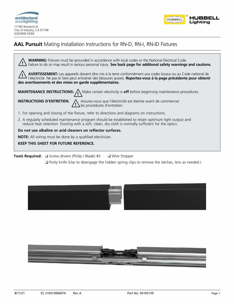
CONTROL BOX INSTALLATION INSTRUCTIONS:
CONTROL BOXSUB-ASSY
(PC SHOWN)
FIXTURE MAIN SUB-ASSY
(RN-D SHOWN)
END CAP SUB-ASSY
8X 10-24SCREWS
FIXTURE ASSEMBLYRECEIVED FROM THE FACTORY
(RN-D ASSY SHOWN)
WARNING: Fixtures must be grounded in accordance with local codes or the National Electrical Code. Failure to do so may result in serious personal injury. See back page for additonal safety warnings and cautions.
AVERTISSEMENT: Les appareils doivent être mis à la terre conformément aux codes locaux ou au Code national de l’électricité. Ne pas le faire peut entraîner des blessures graves. Reportez-vous à la page précédente pour obtenir des avertissements et des mises en garde supplémentaires.
MAINTENANCE INSTRUCTIONS: Make certain electricity is off before beginning maintenance procedures.
INSTRUCTIONS D’ENTRETIEN: Assurez-vous que l’électricité est éteinte avant de commencer les procédures d’entretien.
1. For opening and closing of the fixture, refer to directions and diagrams on instructions.
2. A regularly scheduled maintenance program should be established to retain optimum light output and reduce heat retention. Dusting with a soft, clean, dry cloth is normally sufficient for the optics.
Do not use alkaline or acid cleaners on reflector surfaces.
NOTE: All wiring must be done by a qualified electrician.
KEEP THIS SHEET FOR FUTURE REFERENCE.
!
!
!
!
Tools Required: q Screw drivers (Philip / Blade) #2 q Wire Stripper
q Putty knife (Use to disengage the hidden spring clips to remove the latches, lens as needed.)
AAL Pursuit Mating Installation Instructions for RN-D, RN-I, RN-ID Fixtures
© 2021 AAL • 17760 Rowland Street • City of Industry, CA 91748 • 626-968-5666 Page 4
CONTROL BOX INSTALLATION INSTRUCTIONS:
STEPS:
1. Turn off power to the unit and take proper safety precautions.
2. For arm mounting option refer on the installation instructions # 93083863.
3. FIXTURE PREPARATION: A. Slide a putty knife under the side Latches to disengage the hidden spring
clips and remove the Latches. B. Pry the LED/DRIVER Sub-Assembly up, remove Safety Cables, disconnect Power Cables,
and remove it from the External Housing.
4. Determine which side the Control Box sub-assembly to be located.
5. EXTERNAL HOUSING PREPARATION: A. Install Endcap and Control Box sub-assembly to External Housing. B. Pull line voltage wires thru and make connection to the fixture Power Cable. C. Reconnect the Power Cable to the LED/DRIVER Sub-Assembly and reattach the
Safety Cables. D. Snap in the LED/DRIVER Sub-Assembly. E. Connect the plug Power Cord to LED/DRIVER Sub-Assembly. F. Insert the Lens and install the Latches to retain the Lens.
6. Turn on power and check for operation.
7. Installation complete.
SPRING CLIP(BOTH ENDS)
CONTROLS POWERCABLE
EXTERNALHOUSING
END CAPSUB-ASSY
4X 10-24SCREWS
LENS
LED / DRIVERSUB-ASSEMBLY
4X 10-24SCREWS CONTROL BOX
SUB-ASSY
PUTTY KNIFE
POWERCABLE
AAL Pursuit Mating Installation Instructions for RN-D, RN-I, RN-ID Fixtures
© 2021 AAL • 17760 Rowland Street • City of Industry, CA 91748 • 626-968-5666 Page 5
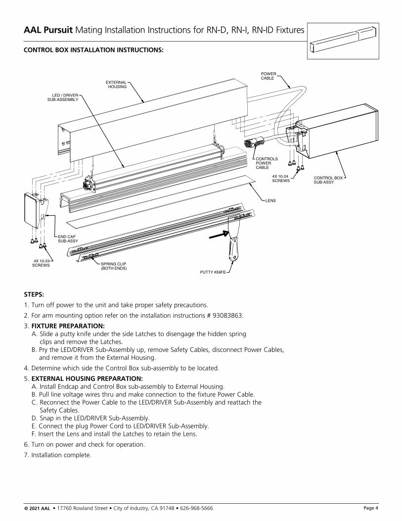
FIXTURE MATING INSTALLATION INSTRUCTIONS:
3X FIXTURE MAIN SUB-ASSY
(RN-D SHOWN)
2X END CAP SUB-ASSY
24X 10-24SCREWS
2X PLUG POWER CORD
2X MATING PLATE / GASKETSUB-ASSY
WARNING: Fixtures must be grounded in accordance with local codes or the National Electrical Code. Failure to do so may result in serious personal injury. See back page for additonal safety warnings and cautions.
AVERTISSEMENT: Les appareils doivent être mis à la terre conformément aux codes locaux ou au Code national de l’électricité. Ne pas le faire peut entraîner des blessures graves. Reportez-vous à la page précédente pour obtenir des avertissements et des mises en garde supplémentaires.
MAINTENANCE INSTRUCTIONS: Make certain electricity is off before beginning maintenance procedures.
INSTRUCTIONS D’ENTRETIEN: Assurez-vous que l’électricité est éteinte avant de commencer les procédures d’entretien.
1. For opening and closing of the fixture, refer to directions and diagrams on instructions.
2. A regularly scheduled maintenance program should be established to retain optimum light output and reduce heat retention. Dusting with a soft, clean, dry cloth is normally sufficient for the optics.
Do not use alkaline or acid cleaners on reflector surfaces.
NOTE: All wiring must be done by a qualified electrician.
KEEP THIS SHEET FOR FUTURE REFERENCE.
!
!
!
!
Tools Required: q Screw drivers (Philip / Blade) #2 q Wire Stripper
q Putty knife (Use to disengage the hidden spring clips to remove the latches, lens as needed.)
AAL Pursuit Mating Installation Instructions for RN-D, RN-I, RN-ID Fixtures
© 2021 AAL • 17760 Rowland Street • City of Industry, CA 91748 • 626-968-5666 Page 6
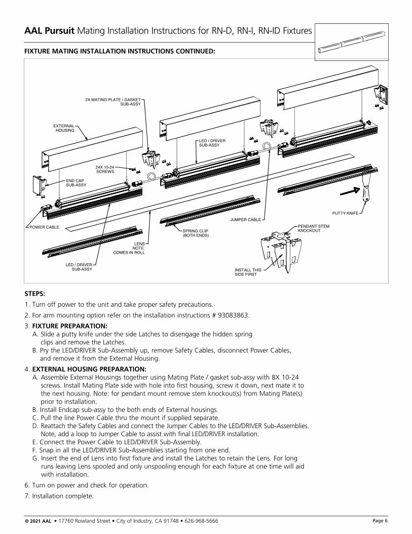
FIXTURE MATING INSTALLATION INSTRUCTIONS CONTINUED:
SPRING CLIP(BOTH ENDS)
LED / DRIVERSUB-ASSY
24X 10-24SCREWS
END CAPSUB-ASSY
LED / DRIVERSUB-ASSY
2X MATING PLATE / GASKETSUB-ASSY
LENSNOTE:
COMES IN ROLL
EXTERNALHOUSING
PUTTY KNIFEJUMPER CABLE
POWER CABLE PENDANT STEMKNOCKOUT
INSTALL THIS SIDE FIRST
STEPS:
1. Turn off power to the unit and take proper safety precautions.
2. For arm mounting option refer on the installation instructions # 93083863.
3. FIXTURE PREPARATION: A. Slide a putty knife under the side Latches to disengage the hidden spring
clips and remove the Latches. B. Pry the LED/DRIVER Sub-Assembly up, remove Safety Cables, disconnect Power Cables,
and remove it from the External Housing.
4. EXTERNAL HOUSING PREPARATION: A. Assemble External Housings together using Mating Plate / gasket sub-assy with 8X 10-24
screws. Install Mating Plate side with hole into first housing, screw it down, next mate it to the next housing. Note: for pendant mount remove stem knockout(s) from Mating Plate(s) prior to installation.
B. Install Endcap sub-assy to the both ends of External housings. C. Pull the line Power Cable thru the mount if supplied separate. D. Reattach the Safety Cables and connect the Jumper Cables to the LED/DRIVER Sub-Assemblies.
Note, add a loop to Jumper Cable to assist with final LED/DRIVER installation. E. Connect the Power Cable to LED/DRIVER Sub-Assembly. F. Snap in all the LED/DRIVER Sub-Assemblies starting from one end. G. Insert the end of Lens into first fixture and install the Latches to retain the Lens. For long
runs leaving Lens spooled and only unspooling enough for each fixture at one time will aid with installation.
6. Turn on power and check for operation.
7. Installation complete.
AAL Pursuit Mating Installation Instructions for RN-D, RN-I, RN-ID Fixtures
© 2021 AAL • 17760 Rowland Street • City of Industry, CA 91748 • 626-968-5666 Page 7
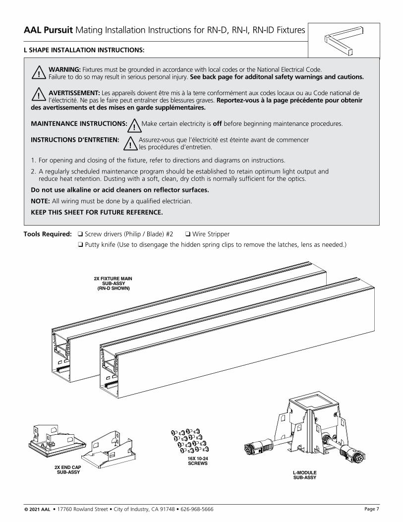
L SHAPE INSTALLATION INSTRUCTIONS:
WARNING: Fixtures must be grounded in accordance with local codes or the National Electrical Code. Failure to do so may result in serious personal injury. See back page for additonal safety warnings and cautions.
AVERTISSEMENT: Les appareils doivent être mis à la terre conformément aux codes locaux ou au Code national de l’électricité. Ne pas le faire peut entraîner des blessures graves. Reportez-vous à la page précédente pour obtenir des avertissements et des mises en garde supplémentaires.
MAINTENANCE INSTRUCTIONS: Make certain electricity is off before beginning maintenance procedures.
INSTRUCTIONS D’ENTRETIEN: Assurez-vous que l’électricité est éteinte avant de commencer les procédures d’entretien.
1. For opening and closing of the fixture, refer to directions and diagrams on instructions.
2. A regularly scheduled maintenance program should be established to retain optimum light output and reduce heat retention. Dusting with a soft, clean, dry cloth is normally sufficient for the optics.
Do not use alkaline or acid cleaners on reflector surfaces.
NOTE: All wiring must be done by a qualified electrician.
KEEP THIS SHEET FOR FUTURE REFERENCE.
!
!
!
!
Tools Required: q Screw drivers (Philip / Blade) #2 q Wire Stripper
q Putty knife (Use to disengage the hidden spring clips to remove the latches, lens as needed.)
2X FIXTURE MAIN SUB-ASSY
(RN-D SHOWN)
2X END CAP SUB-ASSY
16X 10-24SCREWS
L-MODULESUB-ASSY
AAL Pursuit Mating Installation Instructions for RN-D, RN-I, RN-ID Fixtures
© 2021 AAL • 17760 Rowland Street • City of Industry, CA 91748 • 626-968-5666 Page 8
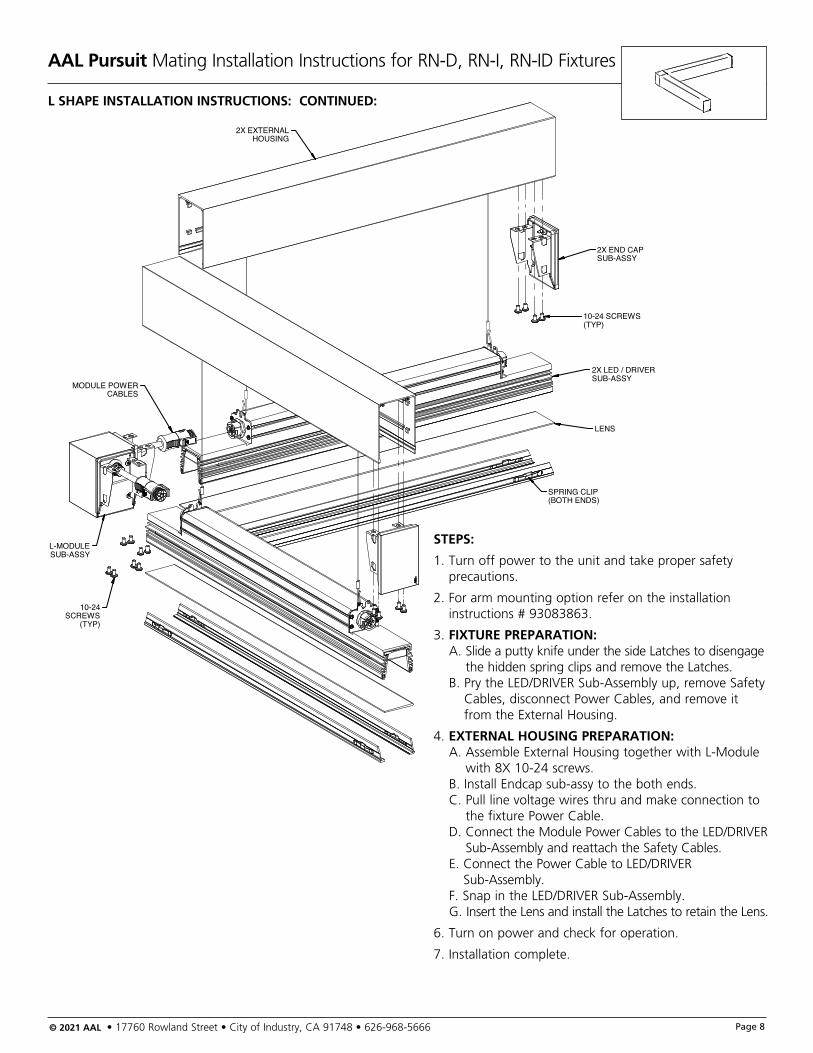
SPRING CLIP(BOTH ENDS)
2X LED / DRIVERSUB-ASSY
10-24 SCREWS(TYP)
2X END CAPSUB-ASSY
2X EXTERNALHOUSING
LENS
10-24SCREWS
(TYP)
L-MODULESUB-ASSY
MODULE POWERCABLES
L SHAPE INSTALLATION INSTRUCTIONS: CONTINUED:
STEPS:
1. Turn off power to the unit and take proper safety precautions.
2. For arm mounting option refer on the installation instructions # 93083863.
3. FIXTURE PREPARATION: A. Slide a putty knife under the side Latches to disengage
the hidden spring clips and remove the Latches. B. Pry the LED/DRIVER Sub-Assembly up, remove Safety
Cables, disconnect Power Cables, and remove it from the External Housing.
4. EXTERNAL HOUSING PREPARATION: A. Assemble External Housing together with L-Module
with 8X 10-24 screws. B. Install Endcap sub-assy to the both ends. C. Pull line voltage wires thru and make connection to
the fixture Power Cable. D. Connect the Module Power Cables to the LED/DRIVER
Sub-Assembly and reattach the Safety Cables. E. Connect the Power Cable to LED/DRIVER
Sub-Assembly. F. Snap in the LED/DRIVER Sub-Assembly. G. Insert the Lens and install the Latches to retain the Lens.
6. Turn on power and check for operation.
7. Installation complete.
AAL Pursuit Mating Installation Instructions for RN-D, RN-I, RN-ID Fixtures
© 2021 AAL • 17760 Rowland Street • City of Industry, CA 91748 • 626-968-5666 Page 9
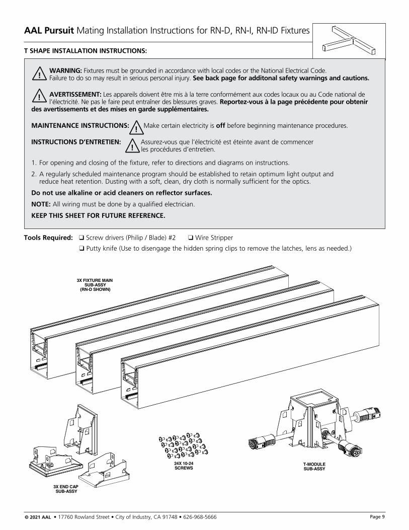
T SHAPE INSTALLATION INSTRUCTIONS:
WARNING: Fixtures must be grounded in accordance with local codes or the National Electrical Code. Failure to do so may result in serious personal injury. See back page for additonal safety warnings and cautions.
AVERTISSEMENT: Les appareils doivent être mis à la terre conformément aux codes locaux ou au Code national de l’électricité. Ne pas le faire peut entraîner des blessures graves. Reportez-vous à la page précédente pour obtenir des avertissements et des mises en garde supplémentaires.
MAINTENANCE INSTRUCTIONS: Make certain electricity is off before beginning maintenance procedures.
INSTRUCTIONS D’ENTRETIEN: Assurez-vous que l’électricité est éteinte avant de commencer les procédures d’entretien.
1. For opening and closing of the fixture, refer to directions and diagrams on instructions.
2. A regularly scheduled maintenance program should be established to retain optimum light output and reduce heat retention. Dusting with a soft, clean, dry cloth is normally sufficient for the optics.
Do not use alkaline or acid cleaners on reflector surfaces.
NOTE: All wiring must be done by a qualified electrician.
KEEP THIS SHEET FOR FUTURE REFERENCE.
!
!
!
!
Tools Required: q Screw drivers (Philip / Blade) #2 q Wire Stripper
q Putty knife (Use to disengage the hidden spring clips to remove the latches, lens as needed.)
3X FIXTURE MAIN SUB-ASSY
(RN-D SHOWN)
3X END CAP SUB-ASSY
24X 10-24SCREWS
T-MODULESUB-ASSY
AAL Pursuit Mating Installation Instructions for RN-D, RN-I, RN-ID Fixtures
© 2021 AAL • 17760 Rowland Street • City of Industry, CA 91748 • 626-968-5666 Page 10
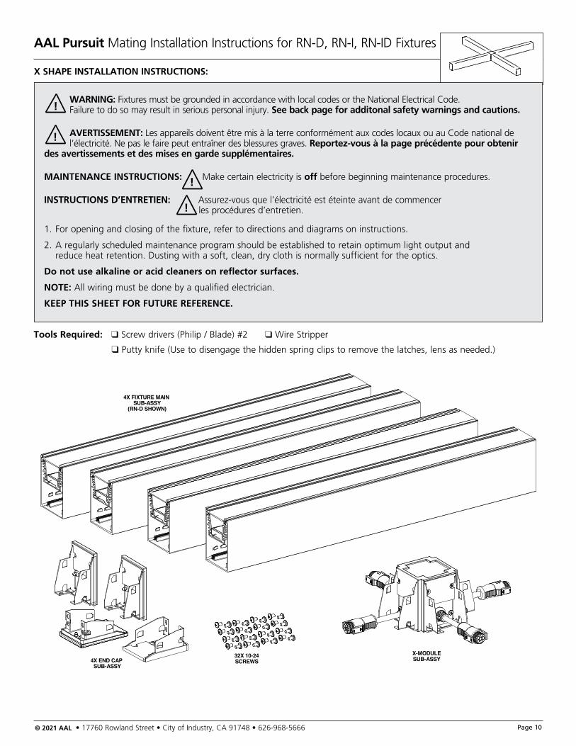
X SHAPE INSTALLATION INSTRUCTIONS:
WARNING: Fixtures must be grounded in accordance with local codes or the National Electrical Code. Failure to do so may result in serious personal injury. See back page for additonal safety warnings and cautions.
AVERTISSEMENT: Les appareils doivent être mis à la terre conformément aux codes locaux ou au Code national de l’électricité. Ne pas le faire peut entraîner des blessures graves. Reportez-vous à la page précédente pour obtenir des avertissements et des mises en garde supplémentaires.
MAINTENANCE INSTRUCTIONS: Make certain electricity is off before beginning maintenance procedures.
INSTRUCTIONS D’ENTRETIEN: Assurez-vous que l’électricité est éteinte avant de commencer les procédures d’entretien.
1. For opening and closing of the fixture, refer to directions and diagrams on instructions.
2. A regularly scheduled maintenance program should be established to retain optimum light output and reduce heat retention. Dusting with a soft, clean, dry cloth is normally sufficient for the optics.
Do not use alkaline or acid cleaners on reflector surfaces.
NOTE: All wiring must be done by a qualified electrician.
KEEP THIS SHEET FOR FUTURE REFERENCE.
!
!
!
!
Tools Required: q Screw drivers (Philip / Blade) #2 q Wire Stripper
q Putty knife (Use to disengage the hidden spring clips to remove the latches, lens as needed.)
4X FIXTURE MAIN SUB-ASSY
(RN-D SHOWN)
4X END CAP SUB-ASSY
32X 10-24SCREWS
X-MODULESUB-ASSY
AAL Pursuit Mating Installation Instructions for RN-D, RN-I, RN-ID Fixtures
© 2021 AAL • 17760 Rowland Street • City of Industry, CA 91748 • 626-968-5666 Page 11
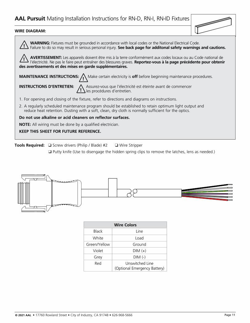
WIRE DIAGRAM:
WARNING: Fixtures must be grounded in accordance with local codes or the National Electrical Code. Failure to do so may result in serious personal injury. See back page for additonal safety warnings and cautions.
AVERTISSEMENT: Les appareils doivent être mis à la terre conformément aux codes locaux ou au Code national de l’électricité. Ne pas le faire peut entraîner des blessures graves. Reportez-vous à la page précédente pour obtenir des avertissements et des mises en garde supplémentaires.
MAINTENANCE INSTRUCTIONS: Make certain electricity is off before beginning maintenance procedures.
INSTRUCTIONS D’ENTRETIEN: Assurez-vous que l’électricité est éteinte avant de commencer les procédures d’entretien.
1. For opening and closing of the fixture, refer to directions and diagrams on instructions.
2. A regularly scheduled maintenance program should be established to retain optimum light output and reduce heat retention. Dusting with a soft, clean, dry cloth is normally sufficient for the optics.
Do not use alkaline or acid cleaners on reflector surfaces.
NOTE: All wiring must be done by a qualified electrician.
KEEP THIS SHEET FOR FUTURE REFERENCE.
!
!
!
!
Tools Required: q Screw drivers (Philip / Blade) #2 q Wire Stripper
q Putty knife (Use to disengage the hidden spring clips to remove the latches, lens as needed.)
Wire Colors
Black Line
White Load
Green/Yellow Ground
Violet DIM (+)
Grey DIM (-)
Red Unswitched Line (Optional Emergency Battery)
AAL Pursuit Mating Installation Instructions for RN-D, RN-I, RN-ID Fixtures
© 2021 AAL • 17760 Rowland Street • City of Industry, CA 91748 • 626-968-5666 Page 12
WARNING: Fixtures must be grounded in accordance with local codes or the National Electrical Code. Failure to do so may result in serious personal injury. See back page for additonal safety warnings and cautions.
AVERTISSEMENT: Les appareils doivent être mis à la terre conformément aux codes locaux ou au Code national de l’électricité. Ne pas le faire peut entraîner des blessures graves. Reportez-vous à la page précédente pour obtenir des avertissements et des mises en garde supplémentaires.
MAINTENANCE INSTRUCTIONS: Make certain electricity is off before beginning maintenance procedures.
INSTRUCTIONS D’ENTRETIEN: Assurez-vous que l’électricité est éteinte avant de commencer les procédures d’entretien.
1. For opening and closing of the fixture, refer to directions and diagrams on instructions.
2. A regularly scheduled maintenance program should be established to retain optimum light output and reduce heat retention. Dusting with a soft, clean, dry cloth is normally sufficient for the optics.
Do not use alkaline or acid cleaners on reflector surfaces.
NOTE: All wiring must be done by a qualified electrician.
KEEP THIS SHEET FOR FUTURE REFERENCE.
!
!
!
!
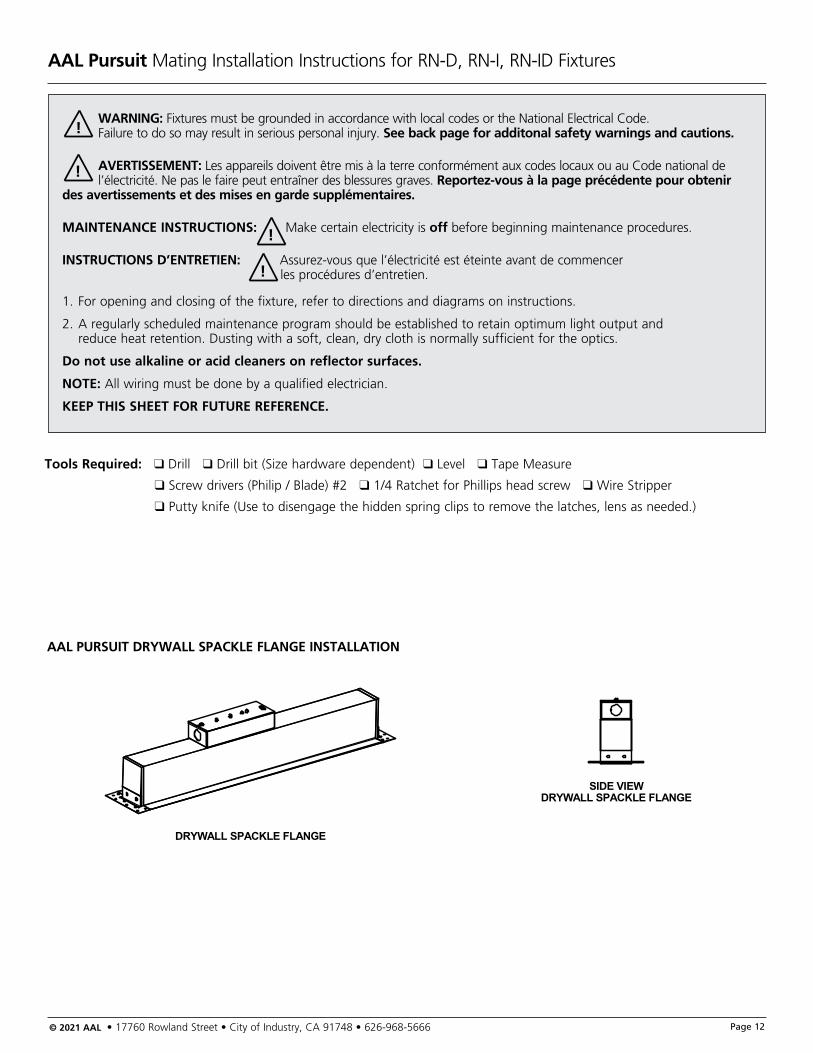
Tools Required: q Drill q Drill bit (Size hardware dependent) q Level q Tape Measure
q Screw drivers (Philip / Blade) #2 q 1/4 Ratchet for Phillips head screw q Wire Stripper
q Putty knife (Use to disengage the hidden spring clips to remove the latches, lens as needed.)
AAL PURSUIT DRYWALL SPACKLE FLANGE INSTALLATION
DRYWALL SPACKLE FLANGE
SIDE VIEWDRYWALL SPACKLE FLANGE

AAL Pursuit Mating Installation Instructions for RN-D, RN-I, RN-ID Fixtures
© 2021 AAL • 17760 Rowland Street • City of Industry, CA 91748 • 626-968-5666 Page 13
DRYWALL SPACKLE FLANGE
SIDE VIEWDRYWALL SPACKLE FLANGE
Drywall Spackle FlangeSINGLE FIXTURE RNR-DS™ INSTALLATION:
SECTION VIEWEXTERNAL HOUSINGMOUNTING DETAIL
SPACKLEFLANGE
DRYWALL
LIGHT ENGINE
LENSLATCH
HOUSING
FIXTURE COMPONENTS SHIP UN-ASSEMBLE
FIXTURE ASSEMBLY
J-BOX
AAL Pursuit Mating Installation Instructions for RN-D, RN-I, RN-ID Fixtures
© 2021 AAL • 17760 Rowland Street • City of Industry, CA 91748 • 626-968-5666 Page 14
DRYWALL SPACKLE FLANGE
SIDE VIEWDRYWALL SPACKLE FLANGE
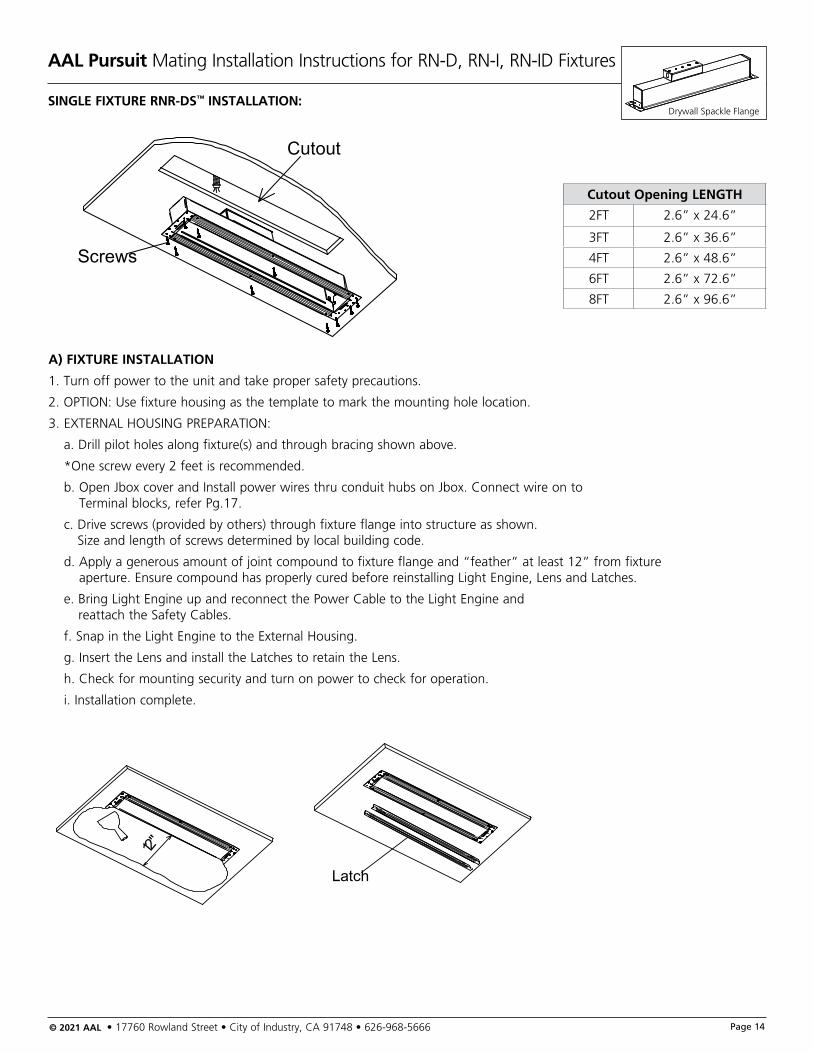
Drywall Spackle FlangeSINGLE FIXTURE RNR-DS™ INSTALLATION:
Cutout
Screws
Latch
12"
A) FIXTURE INSTALLATION
1. Turn off power to the unit and take proper safety precautions.
2. OPTION: Use fixture housing as the template to mark the mounting hole location.
3. EXTERNAL HOUSING PREPARATION:
a. Drill pilot holes along fixture(s) and through bracing shown above.
*One screw every 2 feet is recommended.
b. Open Jbox cover and Install power wires thru conduit hubs on Jbox. Connect wire on to Terminal blocks, refer Pg.17.
c. Drive screws (provided by others) through fixture flange into structure as shown. Size and length of screws determined by local building code.
d. Apply a generous amount of joint compound to fixture flange and “feather” at least 12” from fixture aperture. Ensure compound has properly cured before reinstalling Light Engine, Lens and Latches.
e. Bring Light Engine up and reconnect the Power Cable to the Light Engine and reattach the Safety Cables.
f. Snap in the Light Engine to the External Housing.
g. Insert the Lens and install the Latches to retain the Lens.
h. Check for mounting security and turn on power to check for operation.
i. Installation complete.
Cutout Opening LENGTH
2FT 2.6” x 24.6”
3FT 2.6” x 36.6”
4FT 2.6” x 48.6”
6FT 2.6” x 72.6”
8FT 2.6” x 96.6”
AAL Pursuit Mating Installation Instructions for RN-D, RN-I, RN-ID Fixtures
© 2021 AAL • 17760 Rowland Street • City of Industry, CA 91748 • 626-968-5666 Page 15
DRYWALL SPACKLE FLANGE
SIDE VIEWDRYWALL SPACKLE FLANGE
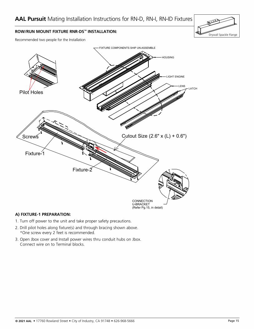
Drywall Spackle FlangeROW/RUN MOUNT FIXTURE RNR-DS™ INSTALLATION:
Cutout Size (2.6" x (L) + 0.6")
Pilot Holes
Screws
Fixture-1
Fixture-2
CONNECTIONU-BRACKET(Refer Pg.15, in detail)
LIGHT ENGINE
LENSLATCH
HOUSING
FIXTURE COMPONENTS SHIP UN-ASSEMBLE
A) FIXTURE-1 PREPARATION:
1. Turn off power to the unit and take proper safety precautions.
2. Drill pilot holes along fixture(s) and through bracing shown above. *One screw every 2 feet is recommended.
3. Open Jbox cover and Install power wires thru conduit hubs on Jbox. Connect wire on to Terminal blocks.
Recommended two people for the Installation
AAL Pursuit Mating Installation Instructions for RN-D, RN-I, RN-ID Fixtures
© 2021 AAL • 17760 Rowland Street • City of Industry, CA 91748 • 626-968-5666 Page 16
DRYWALL SPACKLE FLANGE
SIDE VIEWDRYWALL SPACKLE FLANGE
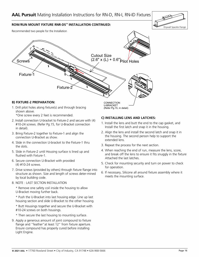
Drywall Spackle FlangeROW/RUN MOUNT FIXTURE RNR-DS™ INSTALLATION CONTINUED:
Recommended two people for the Installation
Pilot HolesCutout Size(2.6" x (L) + 0.6")Screws
Fixture-1
Fixture-2
CONNECTIONU-BRACKET(Refer Pg.15, in detail)
B) FIXTURE-2 PREPARATION:
1. Drill pilot holes along fixture(s) and through bracing shown above. *One screw every 2 feet is recommended.
2. Install connection U‐bracket to Fixture‐2 and secure with (4) #10‐24 screws. (Refer Pg.15, for U‐Bracket connection in detail).
3. Bring Fixture‐2 together to Fixture‐1 and align the connection U‐Bracket as show.
4. Slide in the connection U‐bracket to the Fixture‐1 thru the slots.
5. Slide in Fixture‐2 until Housing surface is lined up and flushed with Fixture‐1.
6. Secure connection U‐Bracket with provided (4) #10‐24 screws.
7. Drive screws (provided by others) through fixture flange into structure as shown. Size and length of screws deter‐mined by local building code.
8. NOTE : LAST SECTION INSTALLATION
* Remove one safety coil inside the housing to allow U‐Bracket moving further back.
* Push the U‐Bracket into last housing edge. Line up last housing section and slide U‐Bracket to the other housing.
* Butt Housings together and secure the U‐Bracket with #10‐24 screws on both housings.
* Then secure the last housing to mounting surface.
9. Apply a generous amount of joint compound to fixture flange and “feather”at least 12” from fixture aperture. Ensure compound has properly cured before installing Light Engine.
C) INSTALLING LENS AND LATCHES:
1. Install the lens and butt the end to the cap gasket, and Install the first latch and snap it in the housing.
2. Align the lens and install the second latch and snap it in the housing. The second person help to support the extended lens.
3. Repeat the process for the next section.
4. When reaching the end of run, measure the lens, score, and break off the lens to ensure it fits snuggly in the fixture Attached the last latches.
5. Check for mounting security and turn on power to check for operation.
6. If necessary, Silicone all around fixture assembly where it meets the mounting surface.
AAL Pursuit Mating Installation Instructions for RN-D, RN-I, RN-ID Fixtures
© 2021 AAL • 17760 Rowland Street • City of Industry, CA 91748 • 626-968-5666 Page 17
DRYWALL SPACKLE FLANGE
SIDE VIEWDRYWALL SPACKLE FLANGE
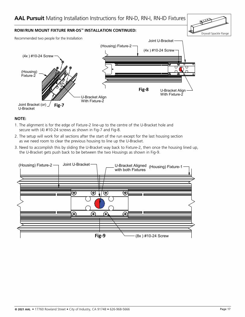
Drywall Spackle FlangeROW/RUN MOUNT FIXTURE RNR-DS™ INSTALLATION CONTINUED:
Recommended two people for the Installation
Fig-7
Fig-8
(Housing) Fixture-2
Joint Bracket (or)U-Bracket
(4x ) #10-24 Screw
(Housing) Fixture-2Joint U-Bracket
U-Bracket AlignWith Fixture-2
(4x ) #10-24 Screw
U-Bracket AlignWith Fixture-2
Fig-9
(Housing) Fixture-2 (Housing) Fixture-1Joint U-Bracket U-Bracket Alignedwith both Fixtures
(8x ) #10-24 Screw
NOTE:
1. The alignment is for the edge of Fixture‐2 line‐up to the centre of the U‐Bracket hole and secure with (4) #10‐24 screws as shown in Fig‐7 and Fig‐8.
2. The setup will work for all sections after the start of the run except for the last housing section as we need room to clear the previous housing to line up the U‐Bracket.
3. Need to accomplish this by sliding the U‐Bracket way back to Fixture‐2, then once the housing lined up, the U‐Bracket gets push back to be between the two Housings as shown in Fig‐9.

AAL Pursuit Mating Installation Instructions for RN-D, RN-I, RN-ID Fixtures
© 2021 AAL • 17760 Rowland Street • City of Industry, CA 91748 • 626-968-5666 Page 18
DRYWALL SPACKLE FLANGE
SIDE VIEWDRYWALL SPACKLE FLANGE
Drywall Spackle FlangeROW/RUN WALL MOUNT FIXTURE RNR-DS™ INSTALLATION:
Recommended two people for the Installation
Pilot Holes
Fixture-1
Screws Fixture-2
Cutout Size2.6" x (L)+0.6"
U-Bracket
Wal
l
J-Box
A) FIXTURE-1 PREPARATION:
1. Turn off power to the unit and take proper safety precautions.
2. Drill pilot holes along fixture(s) and through bracing shown above. *One screw every 2 feet is recommended.
3. Open Jbox cover and Install power wires thru conduit hubs on Jbox. Connect wire on to Terminal blocks.
4. Draw fixture‐1 tight to Wall using Wood Screws through the appropriate Holes on fixture housing. Tighten until flange is snug with wall.
B) FIXTURE-2 PREPARATION:
1. Drill pilot holes along fixture(s) and through bracing shown above. *One screw every 2 feet is recommended.
2. Install connection U‐bracket to Fixture‐2 and secure with (4) #10‐24 screws. (Refer Pg.15, for U‐Bracket connection in detail).
3. Bring Fixture‐2 together to Fixture‐1 and align the connection U‐Bracket as show.
4. Slide in the connection U‐bracket to the Fixture‐1.
5. Slide in Fixture‐2 until Housing surface is lined up and flushed with Fixture‐1.
6. Secure connection U‐Bracket with provided (4) #10‐24 screws.
7. Drive screws (provided by others) through fixture flange into structure as shown. Size and length of screws deter‐mined by local building code.
8. NOTE : (Last section installation)
* Remove one safety coil inside the housing to allow U‐Bracket moving further back.
* Push the U‐Bracket into last housing edge. Line up last housing section and slide U‐Bracket to the other housing.
* Butt Housings together and secure the U‐Bracket with #10‐24 screws on both housings.
* Then secure the last housing to mounting surface.
9. Apply a generous amount of joint compound to fixture flange and “feather” at least 12” from fixture aperture. Ensure compound has properly cured before removing aperture bracket.
C) INSTALLING LENS AND LATCHES:
1. Install the lens and butt the end to the cap gasket, and Install the first latch and snap it in the housing.
2. Align the lens and install the second latch and snap it in the housing. The second person help to support the extended lens.
3. Repeat the process for the next section.
4. When reaching the end of run, measure the lens, score, and break off the lens to ensure it fits snuggly in the fixture Attached the last latches.
5. Check for mounting security and turn on power to check for operation.
6. If necessary, Silicone all around fixture assembly where it meets the mounting surface.
AAL Pursuit Recessed J-Box Installation Instructions
© 2021 AAL • 17760 Rowland Street • City of Industry, CA 91748 • 626-968-5666 Page 19
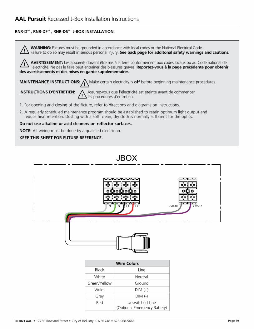
RNR-D™ , RNR-DF™ , RNR-DS™ J-BOX INSTALLATION:
WARNING: Fixtures must be grounded in accordance with local codes or the National Electrical Code. Failure to do so may result in serious personal injury. See back page for additonal safety warnings and cautions.
AVERTISSEMENT: Les appareils doivent être mis à la terre conformément aux codes locaux ou au Code national de l’électricité. Ne pas le faire peut entraîner des blessures graves. Reportez-vous à la page précédente pour obtenir des avertissements et des mises en garde supplémentaires.
MAINTENANCE INSTRUCTIONS: Make certain electricity is off before beginning maintenance procedures.
INSTRUCTIONS D’ENTRETIEN: Assurez-vous que l’électricité est éteinte avant de commencer les procédures d’entretien.
1. For opening and closing of the fixture, refer to directions and diagrams on instructions.
2. A regularly scheduled maintenance program should be established to retain optimum light output and reduce heat retention. Dusting with a soft, clean, dry cloth is normally sufficient for the optics.
Do not use alkaline or acid cleaners on reflector surfaces.
NOTE: All wiring must be done by a qualified electrician.
KEEP THIS SHEET FOR FUTURE REFERENCE.
!
!
!
!
- V0-10
JBOX
+ V0-10N G L1 L2
Wire Colors
Black Line
White Neutral
Green/Yellow Ground
Violet DIM (+)
Grey DIM (-)
Red Unswitched Line (Optional Emergency Battery)
AAL Pursuit Mating Installation Instructions for RN-D, RN-I, RN-ID Fixtures
© 2021 AAL • 17760 Rowland Street • City of Industry, CA 91748 • 626-968-5666 Page 20
Installation warnings and cautions for standard product Avertissements d’installation et mises en garde
WARNING: Make certain all electrical supply is OFF before staring installation or beginning maintenance procedures.
AVERTISSEMENT: S’assurer que toute alimentation possible est COUPÉE avant de commencer l’installation ou l’entretien.
WARNING: Fixtures must be grounded in accordance with local codes or the National Electrical Code. Failure to do so may result in serious personal injury.
AVERTISSEMENT: Les appareils doivent être mis à la terre en conformité avec le Code canadien de l’électricité et les codes locaux. Une non-conformité pourrait conduire à des blessures graves.
WARNING: To prevent wiring damage or abrasion, do not expose wiring to edges of sheet metal or other sharp objects.
AVERTISSEMENT: Pour empêcher l’endommagement ou l’éraflure des fils, empêchez tout contact avec les rebords des parties métalliques.
MAINTENANCE: A regularly scheduled maintenance program should be established to retain optimum light output and reduce heat retention. Dusting with a soft, clean, dry cloth is normally sufficient for the reflector.
ENTRETIEN: Un programme d’entretien régulier devrait être établi pour conserver la luminosité optimale et réduire l’accumulation de chaleur. Un chiffon doux et propre est normalement suffisant pour dépoussiérer le réflecteur optique. Ne pas utiliser de produit nettoyant alcalin ou acide sur les surfaces du réflecteur.
NOTE: All wiring must be done by a qualified electrician.
REMARQUE: Tout le câblage doit être fait par un électricien certifié.
CAUTION: LED fixtures are available in 120 volt input or 277 volt input. Please verify before wiring fixture to field wires. (see lamp label to verify).
MISE EN GARDE: Les appareils d’éclairage à DEL sont offerts pour alimentation à 120 V ou 277 V. Veuillez vérifier avant de raccorder (voir l’étiquette de l’appareil pour confirmer).
CAUTION: Lighted lamp is HOT! Do not touch hot lens, guard or enclosure. DO NOT operate fixtures with missing or damage lens.
MISE EN GARDE: Les ampoules allumées sont CHAUDES! Ne pas toucher leur lentille de diffraction, garde protectrice ou le boîtier. NE PAS allumer d’appareil d’éclairage dont la lentille serait absente ou endommagée.
WARNING: Photocell, if used, must match input voltage to ballast.
AVERTISSEMENT: Toute cellule électrique utilisée doit être de la même tension que le ballast.
! !
!!
!
!
!
!
!
!
!
!
!
!
!
!
Architectural Area Lighting • 17760 Rowland Street • Rowland Height, CA 91748 • Phone: 626-968-5666Due to our continued efforts to improve our products, product specifications are subject to change without notice.
© 2021 HUBBELL LIGHTING, All Rights Reserved • For more information visit our website: www.aal.net • August 17, 2021 10:10 AM
AAL Pursuit Mating Installation Instructions for RN-D, RN-I, RN-ID Fixtures
Installation warnings and cautions for standard products (Continued)Avertissements d’installation et misse en garde..
For warranty see http://www.hubbelllighting.com/resources/warranty
CAUTION: Do not alter, relocate, or remove wiring, lampholders, ballasts, or any other electrical components.
ATTENTION: Ne pas modifier, deplacer ni enlever de cable, de douille de lampe, de ballast ou autre composant electrique.
ADDITIONAL WARNINGS
AVERTISSEMENTS SUPPLÉMENTAIRES
For in ground fixtures
SAFETY WARNING: DO NOT install these fixtures in submersible installations such as fountains or swimming pools. Extreme caution should be taken when installed in paved areas.
Pour les appareils d’éclairage enterrés
DIRECTIVE DE SÉCURITÉ: NE PAS installer ces appareils d’éclairage dans les endroits submergés comme les bassins de fontaines ou les piscines. Une extrême prudence doit être observée lors du montage sur des surfaces pavées.
CAUTION: To help maintain a clean, dry splice compartment, seal the conduit entries with RTV.
MISE EN GARDE: Pour garder le compartiment de jonction des fils propre et sec, scellez les entrées de conduits avec du composé RTV.
CAUTION: Some fixtures are not approved for walk-over areas, reference instruction sheet supplied with fixture.
MISE EN GARDE: Certains appareils d’éclairage ne sont pas approuvés pour montage dans les aires piétonnières. Se référer aux directives de la feuille fournie avec l’appareil.
For Landscape fixtures
WARNING: Portable spear or tree mounts using a cord and plug must be plugged into a receptacle protected by a Ground Fault Circuit Interrupter (GFCI) in accordance with the National Electrical Code. Failure to do so may result in serious personal injury.
Pour appareils d’aménagement paysager
AVERTISSEMENT: Selon le Code national de l’électricité, les appareils portatifs de type lance ou pour montage dans les arbres qui sont munis de cordon et fiche, doivent être branchés dans une prise à protection par disjoncteur de mise à la terre. Une non-conformité pourrait conduire à des blessures graves.
CAUTION: Particular care should be taken not to locate fixtures where small children can reach them if higher wattages are used.
MISE EN GARDE: Une attention particulière devrait être portée pour ne pas installer les appareils d’éclairage dans les endroits accessibles par les jeunes enfants, spécialement si la puis-sance de l’ampoule est élevée.
For 12v Landscape fixtures:
WARNING: To reduce the risk of fire or injury, DO NOT overdrive fixtures with greater that 12 volts or fixture over-heating and short lamp life will occur. DO NOT overload the transformer by installing (or relamping) higher wattages lamps than planned. Note: Total wattage of all lamps connected to one trans-former MUST NOT exceed the capacity of that transformer. DO NOT install fixtures within 10 feet (3.04m) of a pool, spa or fountain.
Pour appareils d’aménagement paysager à 12 V
AVERTISSEMENT: Pour réduire le risque d’incendie ou de blessures, NE PAS alimenter ces appareils d’éclairage à plus de 12 V car ceci conduira à une surchauffe de l’appareil et raccourcira la vie de l’ampoule. NE PAS surcharger le transformateur en utilisant des ampoules de puissance plus élevée que prévu, lors de l’installation ou des remplacements. Remarque: La puissance totale des ampoules connectées à un transformateur NE DOIT PAS excéder la capacité de ce dernier. NE PAS installer ces appareils d’éclairage à moins de 3 m (10 pi) de piscines, spas ou fontaines.
KEEP THIS SHEET FOR FUTURE REFERENCE.CONSERVER LA PRÉSENTE FEUILLE POUR RÉFÉRENCE ULTÉRIEURE.
!
!
!
!
!
!
!
!
!
!
!
!
!
!
!
!