Embed Size (px)
Citation preview
MATHEMATICAL MODELING AND TESTING OF A NEW POLYMER-
BASED IMPACT TOOL DESIGN TO REDUCE VIBRATION-RELATED
BIOMECHANICAL INJURIES
by
Janelle A. Konchar
A thesis submitted to the Faculty of the University of Delaware in partial fulfillment of the requirements for the Degree of Bachelor of Mechanical Engineering with Distinction.
Spring 2006
Copyright 2006 Janelle A. Konchar All Rights Reserved

MATHEMATICAL MODELING AND TESTING OF A NEW POLYMER-
BASED IMPACT TOOL DESIGN TO REDUCE VIBRATION-RELATED
BIOMECHANICAL INJURIES
by
Janelle A. Konchar
Approved: __________________________________________________________ Dr. James L. Glancey, Ph.D. Professor in charge of thesis on behalf of the Advisory Committee Approved: __________________________________________________________ Dr. John Novotny, Ph.D. Committee member from the Department of Mechanical Engineering Approved: __________________________________________________________ Dr. John Pelesko, Ph.D. Committee member from the Board of Senior Thesis Readers Approved: __________________________________________________________ Mohsen Badiey, Ph.D. Chair of the University Committee on Student and Faculty Honors

iii
ACKNOWLEDGMENTS
The author would like to thank Harry McCarty, President of Baltimore
Tool Works, Inc. of Baltimore, Maryland for his support throughout the project. The
author would also like to thank Peter Popper for his initial Matlab code and many
valuable suggestions during the investigation, Matthew Griffith for his help in
prototype fabrication and experimental testing, and machinist Steve Beard for his
assistance in the student shop.
I would also like to acknowledge the continued support of the University
of Delaware Undergraduate Research Department. Finally, I would like to thank Dr.
Glancey for his mentoring over the past two years along with his patience and
guidance throughout the project.

iv
TABLE OF CONTENTS
LIST OF TABLES.......................................................................................................vi LIST OF FIGURES....................................................................................................vii ABSTRACT ............................................................................................................. ix Chapter 1 INTRODUCTION .................................................................................................. 1 1.1 Background................................................................................................. 10 1.2 Objectives of This Study ............................................................................ 11 2 CONCEPTUAL DEVELOPMENT.................................................................... 12 2.1 Mechanics of the Pneumatic Impact Tool .................................................. 12 2.2 Design Considerations for Low Vibration and Sound ............................... 13 2.3 Preliminary Prototypes and Proof of Concept............................................ 14 3 MODELING OF A CONSTRAINED REINFORCED POLYMER
INSERT ............................................................................................................ 17 3.1 Nomenclature ............................................................................................. 17 3.2 Objectives of This Study ............................................................................ 17 3.3 Design of a Polymer Insert ......................................................................... 18 4 MODELING OF THE FORCE TRANSMISSION
CHARACTERISTICS WITH A POLYMER INSERT.................................... 23 4.1 Nomenclature ............................................................................................. 23 4.2 Model Development ................................................................................... 23 4.3 Mathematical Formulation ......................................................................... 25 4.4 Simulations ................................................................................................. 26 4.5 Predictions of Chisel Force During an Impact ........................................... 29 4.6 Effect of Polymer Material Properties on Maximum Output Force ........... 30 4.7 Model Validation........................................................................................ 31 4.8 Effect of Insert Diameter and Insert Length............................................... 32

v
5 DURABILITY AND PERFORMANCE TESTING.......................................... 35 5.1 Methodology for Insert Material Integrity Testing .................................... 35 5.2 Measured Insert Stiffness (Modulus) ......................................................... 36 5.3 Instrumentation and Data Acquisition & Analysis for Vibration and
Sound Emission Testing ............................................................................. 39 5.4 Analysis of Tool Sound Emission .............................................................. 41 5.5 Analysis of Tool Vibration ......................................................................... 43 6 CONCLUSIONS AND RECOMMENDED PATH FORWARD..................... 49 6.1 General Summary ....................................................................................... 49 6.2 Conclusions ................................................................................................ 49 6.3 Suggestions for Future Work...................................................................... 51 REFERENCES ........................................................................................................... 53 APPENDIX A: MATLAB™ CODE ......................................................................... 55 APPENDIX B: COMPLETE SIMULATION OUTPUTS FOR A
PROTOTYPE CHISEL .................................................................. 61 APPENDIX C: OUTPUT FORCE PREDICTION, CONSERVATION OF ENERGY .......................................................................................... 63 APPENDIX D: OUTPUT FORCE PREDICTION, IMPULSE- MOMENTUM THEOREM............................................................ 64 APPENDIX E: CAD DRAWING FOR A DUPLICATE PISTON COMPONENT................................................................................. 65 APPENDIX F: CAD DRAWING FOR A PISTON WITH A FRONT POLYMER INSERT........................................................................ 66 APPENDIX G: CAD DRAWING FOR A PROTOTYPE CHISEL...................... 67 APPENDIX H: CAD DRAWING FOR A POLYMER CHISEL INSERT .......... 68 APPENDIX I: CAD DRAWING FOR THE CHISEL TEST FIXTURE ............. 69
vi
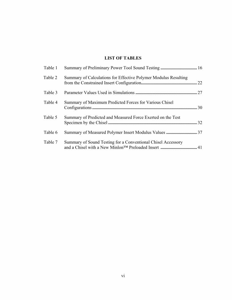
LIST OF TABLES
Table 1 Summary of Preliminary Power Tool Sound Testing ................................ 16
Table 2 Summary of Calculations for Effective Polymer Modulus Resulting from the Constrained Insert Configuration................................................. 22
Table 3 Parameter Values Used in Simulations ...................................................... 27
Table 4 Summary of Maximum Predicted Forces for Various Chisel Configurations ............................................................................................ 30
Table 5 Summary of Predicted and Measured Force Exerted on the Test Specimen by the Chisel .............................................................................. 32
Table 6 Summary of Measured Polymer Insert Modulus Values ........................... 37
Table 7 Summary of Sound Testing for a Conventional Chisel Accessory and a Chisel with a New Minlon™ Preloaded Insert ................................ 41
vii
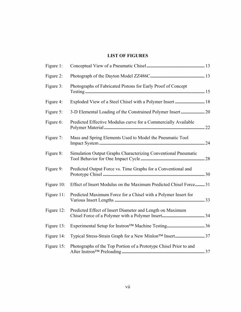
LIST OF FIGURES
Figure 1: Conceptual View of a Pneumatic Chisel ................................................. 13
Figure 2: Photograph of the Dayton Model ZZ486C.............................................. 13
Figure 3: Photographs of Fabricated Pistons for Early Proof of Concept Testing ..................................................................................................... 15
Figure 4: Exploded View of a Steel Chisel with a Polymer Insert ......................... 18
Figure 5: 3-D Elemental Loading of the Constrained Polymer Insert .................... 20
Figure 6: Predicted Effective Modulus curve for a Commercially Available Polymer Material ..................................................................................... 22
Figure 7: Mass and Spring Elements Used to Model the Pneumatic Tool Impact System ......................................................................................... 24
Figure 8: Simulation Output Graphs Characterizing Conventional Pneumatic Tool Behavior for One Impact Cycle ...................................................... 28
Figure 9: Predicted Output Force vs. Time Graphs for a Conventional and Prototype Chisel ...................................................................................... 30
Figure 10: Effect of Insert Modulus on the Maximum Predicted Chisel Force........ 31
Figure 11: Predicted Maximum Force for a Chisel with a Polymer Insert for Various Insert Lengths ............................................................................ 33
Figure 12: Predicted Effect of Insert Diameter and Length on Maximum Chisel Force of a Polymer with a Polymer Insert.................................... 34
Figure 13: Experimental Setup for Instron™ Machine Testing................................ 36
Figure 14: Typical Stress-Strain Graph for a New Minlon™ Insert......................... 37
Figure 15: Photographs of the Top Portion of a Prototype Chisel Prior to and After Instron™ Preloading ...................................................................... 37

viii
Figure 16: The Length of Exposed Polymer After Instron™ Preloading and 1 Hour of Tool Use..................................................................................... 38
Figure 17: LabVIEW Interface for the Data Acquisition and Processing of Sound and Vibration Data ....................................................................... 40
Figure 18: Typical Time Domain Response of Sound for a Conventional Chisel ....................................................................................................... 42
Figure 19: Typical Time Domain Response of Sound for a Prototype Chisel with a Minlon™ Insert ............................................................................ 42
Figure 20: Frequency Spectra of the Sound Pressure Data in Figure 18 for the Conventional Chisel ................................................................................ 43
Figure 21: Frequency Spectra of the Sound Pressure Data in Figure 19 for a Prototype Chisel with a Minlon™ Insert................................................. 43
Figure 22: Typical Time Domain Vibration Response in the Axial Direction at the Hand for a Conventional Chisel .................................................... 44
Figure 23: Typical Time Domain Vibration Response in the Axial Direction at the Hand for a Prototype Chisel with a Minlon™ Insert..................... 45
Figure 24: Overall Frequency Content of the Data in Figure 22 for a Conventional Chisel ................................................................................ 45
Figure 25: Overall Frequency Content of the Data in Figure 23 for a Prototype Chisel with a Minlon™ Insert................................................. 46
Figure 26: Typical Time Domain Lateral Vibration Response at the Elbow for a Conventional Chisel ................................................................................ 47
Figure 27: Typical Time Domain Lateral Vibration Response at the Elbow for a Prototype Chisel with a Minlon™ Insert................................................. 47
Figure 28: Overall Frequency Content of the Data in Figure 26 for a Conventional Chisel ................................................................................ 48
Figure 29: Overall Frequency Content of the Data in Figure 27 for a Prototype Chisel with a Minlon™ Insert................................................. 48

ix
ABSTRACT
Power tools continue to be a source of high vibration in the workplace with
long-term affects on the user contributing to many biomechanical ailments including
Hand-Arm Vibration Syndrome (HAV), Raynaud’s phenomenon, and white finger.
Tools with reciprocating impact components typically produce accelerations that
induce vibration-related injuries unless the daily exposure and/or dosage is limited.
To examine the potential for reducing vibrations emitted from power impact tools, a
model of the impact mechanism has been developed. The first order differential
equations describing the motion of the piston-tool system were simulated in Matlab,
and alternate system designs were evaluated. A modified cutting chisel that included a
high-performance engineering polymer insert was examined. Experiments with a
prototype chisel and insert revealed that acceleration magnitudes in the axial (cutting)
direction were reduced. Simulations and laboratory testing also investigated chisel
force transmission characteristics. While a chisel with a polymer insert slightly
reduced maximum chisel output forces, the reduction was found to be statistically
insignificant (at the 95% confidence level). High frequency testing using an Instron™
material test machine replicated force transmission and demonstrated polymer
degradation as a function of the number of loading cycles. Future work is
recommended on selecting a polymer material and geometry suitable to meet the life-
load requirements.
Keywords: power tool, impact, vibration, biomechanical injury, safety, ergonomics, engineering polymers
10
Chapter 1
INTRODUCTION 1.1 Background
Power tools have a large market presence and are valued as important pieces of
equipment in industries worldwide. Traditional power tools with reciprocating impact
components produce vibration energy that is transmitted to the tool user. Exposure to
vibrations emitted from power impact tools represents a significant workplace hazard
contributing to serious worker health problems and biomechanical injuries such as
Raynaud’s phenomenon, Hand-Arm Vibration Syndrome (HAVS), and white finger.
Recent data specifies that injuries associated with hand tool operation comprised 5.2%
(65,450) of the total work-related injury cases in the United States [1]. Out of these
cases, 26.6% (17,390) involved injury resulting specifically from power hand tools [1].
Hand Arm Vibration (HAV) alone affects two million U.S. workers [2].
The use of tools expose users (workers) to high levels of vibration that can cause
permanent, irreversible damage to blood vessels and nerves in the hand and arm. Often,
hand-arm injuries are accompanied by hearing loss attributed to exposure to high
vibration (and sound). In 2001, the U.S Department of Labor’s Occupational Safety and
Health Administration (OSHA) published ergonomics rules for all general industry
employers [3]. Within this Standard, vibration and the use of hand tools was identified as
one of five ergonomic risks factors leading to injury or symptoms for work-related
musculoskeletal disorders.

11
Excessive HAV exposure from vibrating pneumatic, electric, hydraulic, or
gasoline-powered hand tools can produce an irreversible damage to the hands [2]. As a
result of the increasing ergonomic awareness and employer concern surrounding
occupational vibration injury caused by the regular use of tools in the workplace, this
study has been initiated to develop a new impact tool design to reduce vibration-related
biomechanical injuries. Proof of concept and evaluation of this new design will be
accomplished using a pneumatic-powered hand tool.
1.2 Objectives of this Study
The overall goal of this work is to improve conventional power tool design using
high-performance engineering polymers in order to reduce the harmful biomechanical
ailments associated with their long-term use. Previous work has reported a methodology
for evaluating and modifying the vibration characteristics of power tools for the
characterization of commercially available low-vibration power tools [4].
For the purpose of this study, work will focus on hand-held power tools with an
emphasis on the design and performance of pneumatic-powered reciprocating tools. The
specific objectives are to model the tool system impact mechanism, prototype new tool
components, and evaluate through modeling and testing possible improvements gained
from integrating engineering polymers into traditional power tool designs.
12
Chapter 2
CONCEPTUAL DEVELOPMENT 2.1 Mechanics of the Pneumatic Impact Tool
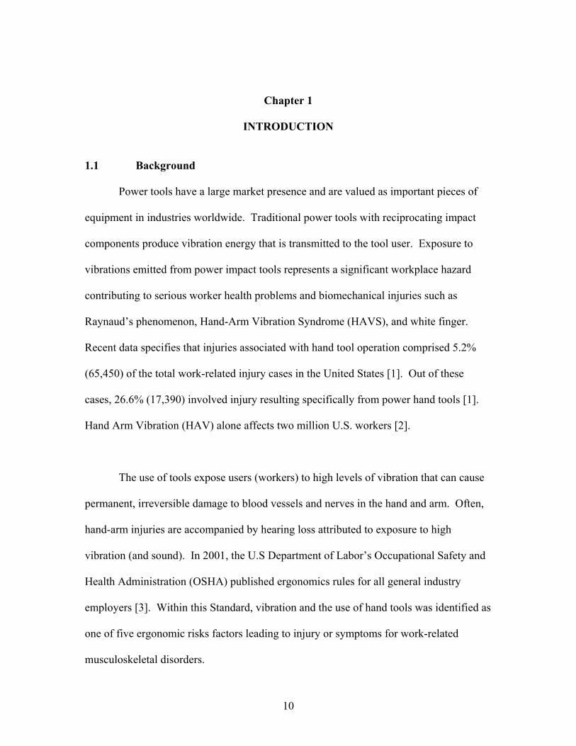
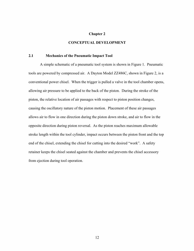
A simple schematic of a pneumatic tool system is shown in Figure 1. Pneumatic
tools are powered by compressed air. A Dayton Model ZZ486C, shown in Figure 2, is a
conventional power chisel. When the trigger is pulled a valve in the tool chamber opens,
allowing air pressure to be applied to the back of the piston. During the stroke of the
piston, the relative location of air passages with respect to piston position changes,
causing the oscillatory nature of the piston motion. Placement of these air passages
allows air to flow in one direction during the piston down stroke, and air to flow in the
opposite direction during piston reversal. As the piston reaches maximum allowable
stroke length within the tool cylinder, impact occurs between the piston front and the top
end of the chisel, extending the chisel for cutting into the desired “work”. A safety
retainer keeps the chisel seated against the chamber and prevents the chisel accessory
from ejection during tool operation.
13
Reciprocating Piston
Air Pressure
SteelChisel
ToolHousing
"Work"
Handle
Figure 1. Conceptual View of a Pneumatic Chisel.
Figure 2. Photograph of the Dayton Model ZZ486C instrumented pneumatic chisel used for experimental testing.
2.2 Design Considerations for Low Vibration and Sound
14
The impact between the steel piston and steel chisel is the principle sources of
vibration generated by the tool system. By integrating advanced engineering polymers
into current power tool designs, the direct metal-to-metal contact between the piston and
chisel components can be eliminated. The ambition of this material substitution, to
dissipate the overall vibration magnitude and remove harmful frequencies of vibration
transmitted to the hand and arm extremities, represents a significant improvement in the
safety of conventional tool systems. Furthermore, this ergonomic performance
enhancement must be achieved without compromising the cutting performance of the
power tool.
2.3 Preliminary Prototypes and Proof of Concept
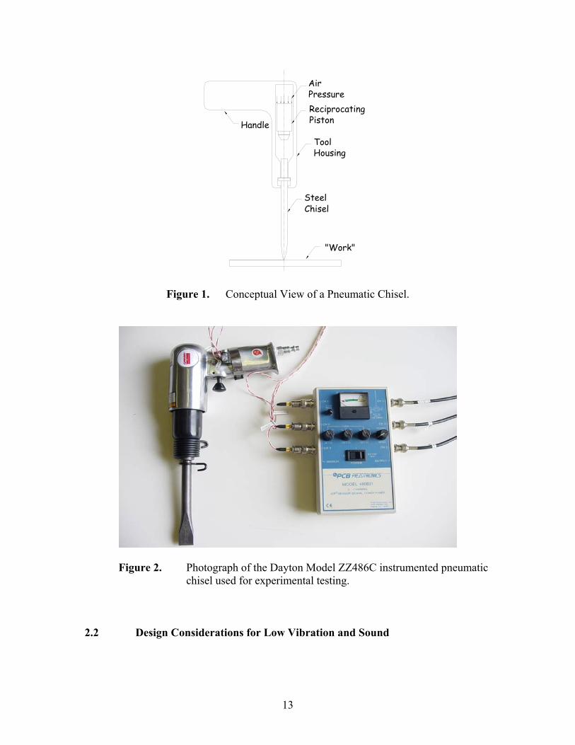
Early demonstration of the potential advantages of integrating polymers into
power tool design was achieved through modification of the piston component.
Duplicate pistons were reliably fabricated at low cost using a standard lathe. Replicate
steel pistons were adapted into two prototype treatments, one incorporating polymer
material at the front impact end of the piston while the second concept added polymer
material to the back surface of the piston (see Figure 3). To accommodate a front insert,
a hole was drilled into the piston allowing a cylindrical polymer insert to be pressed
(interference fit) into the cavity created from the removed steel material. The back insert
configuration required no additional machining to the duplicate piston; a 3 mm thick
circular polymer disk of equal diameter to the rear piston face was secured to the piston
back using a high-performance, two-part epoxy.
15
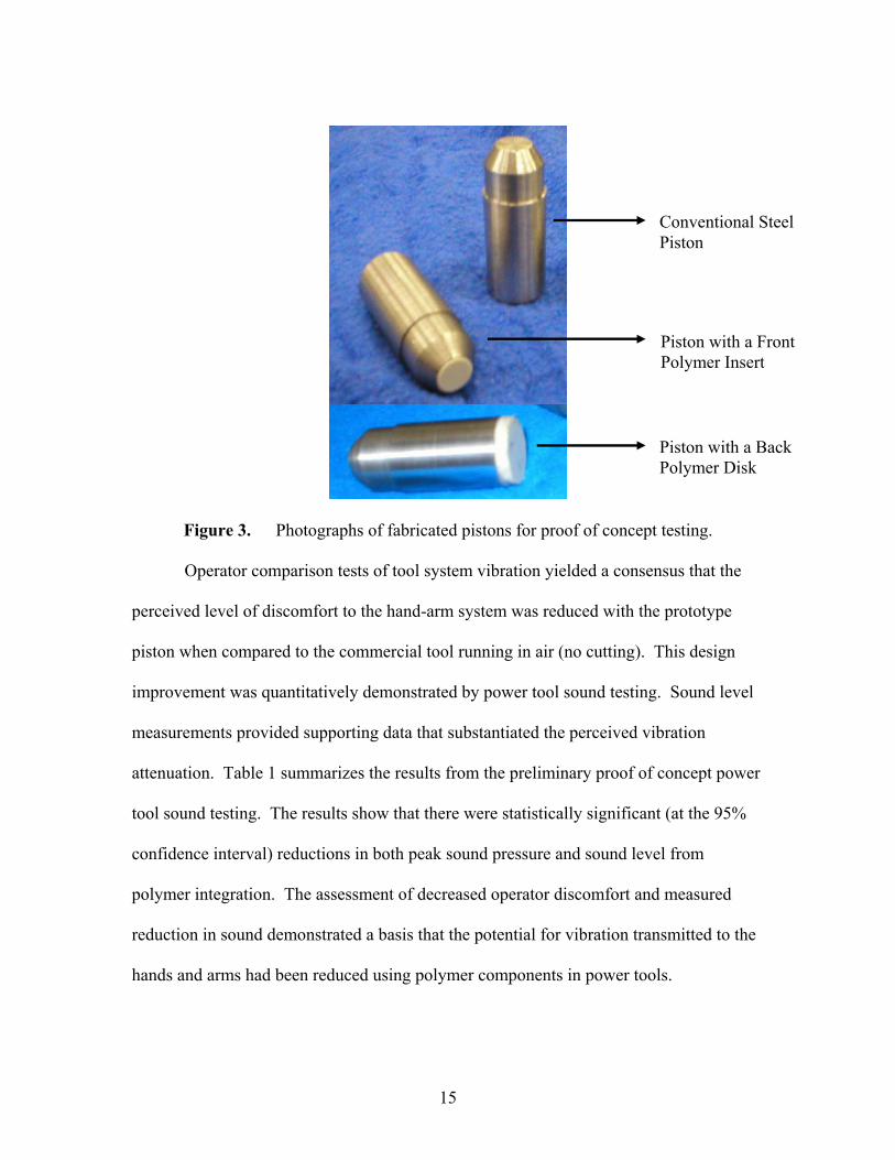
Figure 3. Photographs of fabricated pistons for proof of concept testing.
Operator comparison tests of tool system vibration yielded a consensus that the
perceived level of discomfort to the hand-arm system was reduced with the prototype
piston when compared to the commercial tool running in air (no cutting). This design
improvement was quantitatively demonstrated by power tool sound testing. Sound level
measurements provided supporting data that substantiated the perceived vibration
attenuation. Table 1 summarizes the results from the preliminary proof of concept power
tool sound testing. The results show that there were statistically significant (at the 95%
confidence interval) reductions in both peak sound pressure and sound level from
polymer integration. The assessment of decreased operator discomfort and measured
reduction in sound demonstrated a basis that the potential for vibration transmitted to the
hands and arms had been reduced using polymer components in power tools.
Conventional Steel Piston
Piston with a Front Polymer Insert
Piston with a Back Polymer Disk

16
Table 1. Summary of preliminary power tool sound testing conducted with 2 trials for each piston treatment. The letter next to each numerical result signifies the statistical difference at the 95% confidence level for the different piston treatments. Averages of sound measurements are given for testing done with a faced off chisel for a tool running, no cutting. Distance from power tool to microphone is 3 feet and the data acquisition sampling frequency is 60kHz.
Piston Treatment Sound Pressure (Pa) Sound Level (dB)
Conventional Piston 41.7 126.6
Piston with Front Polymer Insert 23.8 121.8
Piston with Back Polymer Disk 33.0 124.5
Piston prototype work and observations made during testing provided key
groundwork to effectively guide the larger polymer integration study. Visual analysis of
the duplicate pistons after testing revealed that harsh impact occurs between the piston
front and shaft of the cutting accessory. In contrast with design requirements for typical
piston component life, a chisel has shorter functional requirements and is frequently
replaced by tool users during normal industrial use. While piston prototyping and testing
provided a strong foundation for the study, the investigation revealed important design
considerations of component life and tool performance evident when replacing steel with
a reinforced polymer material. In recognition of tool component life requirements
coupled with the frequent replacement of most tools during normal use, a crucial
transition in the project focus was made from piston modification with polymer material
to the design of a chisel accessory to include a reinforced polymer insert.
asp bsp
csp
asl bsl
csl

17
Chapter 3
MODELING OF A CONSTRAINED REINFORCED POLYMER INSERT 3.1 Nomenclature E = elastic modulus σx = stress on the chisel wall σy = stress on the chisel wall, in the same plane but perpendicular to σx σz = stress in the direction of the chisel shaft εx = strain on the chisel wall εy = strain on the chisel wall, in the same plane but perpendicular to εx εz = strain in the direction of the chisel shaft v = Poisson’s ratio E’ = constrained elastic modulus (effective modulus) 3.2 Methodology
Previous studies have reported several performance benefits from fitting a steel
chisel with a polymer cap when compared to a conventional hand-struck bare chisel.
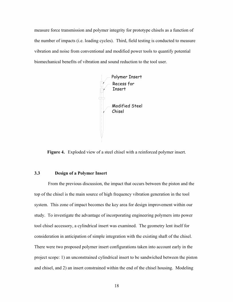
Figure 4 illustrates a conceptual view of a power tool chisel with a polymer insert. The
analysis and testing described herein investigates the feasibility and performance benefits
of a modified accessory chisel including a polymer insert. First, a simple mass-spring
analog is developed to obtain mathematical formulation of the governing equations of
motion of the piston-chisel system. The model is used to design the polymer insert
geometry and configuration based on stresses in the chisel tool end with a polymer.
Furthermore, the model allows for the assessment of the force transmission
characteristics of chisels for different insert materials in order to develop material
property requirements to select a suitable high-performance reinforced polymer. Second,
laboratory experiments are performed using a hydraulic Instron™ test machine to
18
measure force transmission and polymer integrity for prototype chisels as a function of
the number of impacts (i.e. loading cycles). Third, field testing is conducted to measure
vibration and noise from conventional and modified power tools to quantify potential
biomechanical benefits of vibration and sound reduction to the tool user.
Modified SteelChisel
Polymer InsertRecess for Insert
Figure 4. Exploded view of a steel chisel with a reinforced polymer insert.
3.3 Design of a Polymer Insert
From the previous discussion, the impact that occurs between the piston and the
top of the chisel is the main source of high frequency vibration generation in the tool
system. This zone of impact becomes the key area for design improvement within our
study. To investigate the advantage of incorporating engineering polymers into power
tool chisel accessory, a cylindrical insert was examined. The geometry lent itself for
consideration in anticipation of simple integration with the existing shaft of the chisel.
There were two proposed polymer insert configurations taken into account early in the
project scope: 1) an unconstrained cylindrical insert to be sandwiched between the piston
and chisel, and 2) an insert constrained within the end of the chisel housing. Modeling
19
was conducted to examine possible performance advantages of the unconstrained as well
as the constrained insert designs.
Previous work with polymer capped, hand-struck chisels demonstrated that the
stiffness of the polymer must be high in order to transmit and exert high forces onto the
target thus preserving tool performance. Assuming the insert can be modeled as an
axially loaded cylindrical plug, the stiffness can be computed as:
k = E A / t (1)
where, E = polymer modulus A = cross section area t = polymer thickness in impact zone k = cap stiffness
As expected, the polymer modulus must be high to insure high stiffness and peak impact
force transmission. However, it is anticipated that the impact resistance must also be
high to insure durability. The tradeoff between stiffness and durability will be discussed
in more detail a later section.
Within the elastic limit of the material, there is a linear relationship between displacement
and the force attempting to restore the material to equilibrium. Hooke’s law defines the
general relationship between stress and strain in the mechanics of materials,
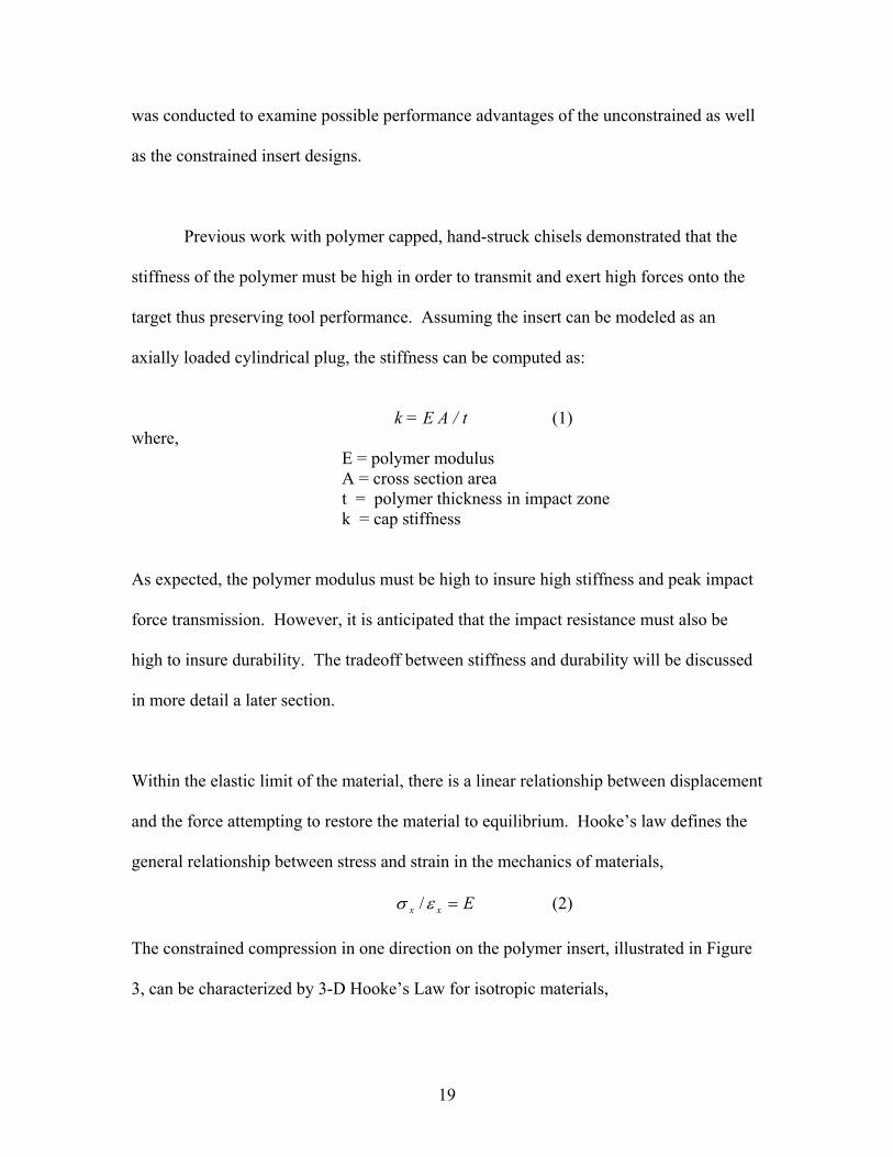
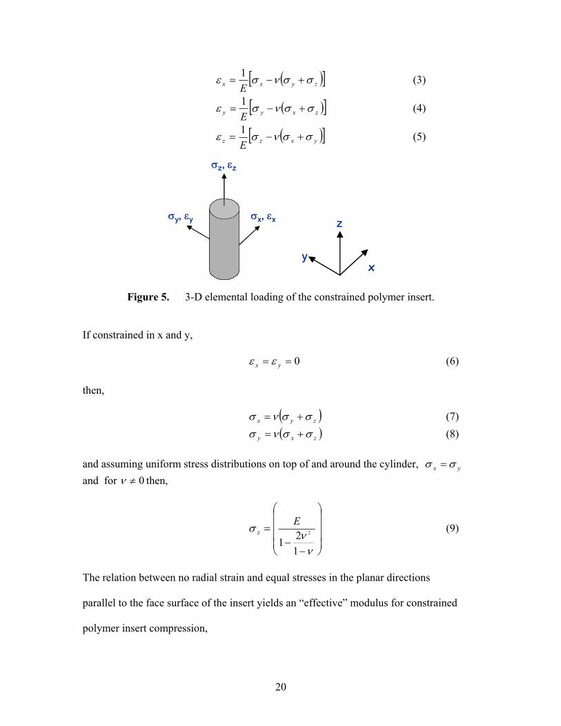
Exx =εσ / (2) The constrained compression in one direction on the polymer insert, illustrated in Figure
3, can be characterized by 3-D Hooke’s Law for isotropic materials,
20
( )[ ]zyxx Eσσνσε +−=
1 (3)
( )[ ]zxyy Eσσνσε +−=
1 (4)
( )[ ]yxzz Eσσνσε +−=
1 (5)
Figure 5. 3-D elemental loading of the constrained polymer insert.
If constrained in x and y,
0== yx εε (6) then,
( )zyx σσνσ += (7) ( )zxy σσνσ += (8)
and assuming uniform stress distributions on top of and around the cylinder, yx σσ = and for 0≠ν then,
−−
=
νν
σ
121
2
Ez (9)
The relation between no radial strain and equal stresses in the planar directions
parallel to the face surface of the insert yields an “effective” modulus for constrained
polymer insert compression,
σz, εz
σx, εxσy, εy
σz, εz
σx, εxσy, εy
x
z
yx
z
y

21
( )12
1' 2 −+−
=νν
νEE (10)
Note that the effective modulus is a function of the elastic modulus of the polymer
material (E) as well as the volume change needed for stress analysis which is indicated by
Poisson’s ratio (v). Both material property values for polymers of interest were obtained
from Dupont Product Information Guides, available online [6].
The derivation for the imposed loading condition demonstrates that constrained
polymer insert performance is not only dependent on the material’s stiffness; the effective
modulus is influenced by the directional deformation characteristics of the polymer.
Engineering materials have Poison’s ratios between 0 and 0.5, with steels in the region of
0.3. Cork, a common bottle stopper, has a value near 0 while materials like rubber that
are almost incompressible approach the upper limit of 0.5. For simple compression,
viscoelastic materials like engineering polymers withstand pressure and expand when
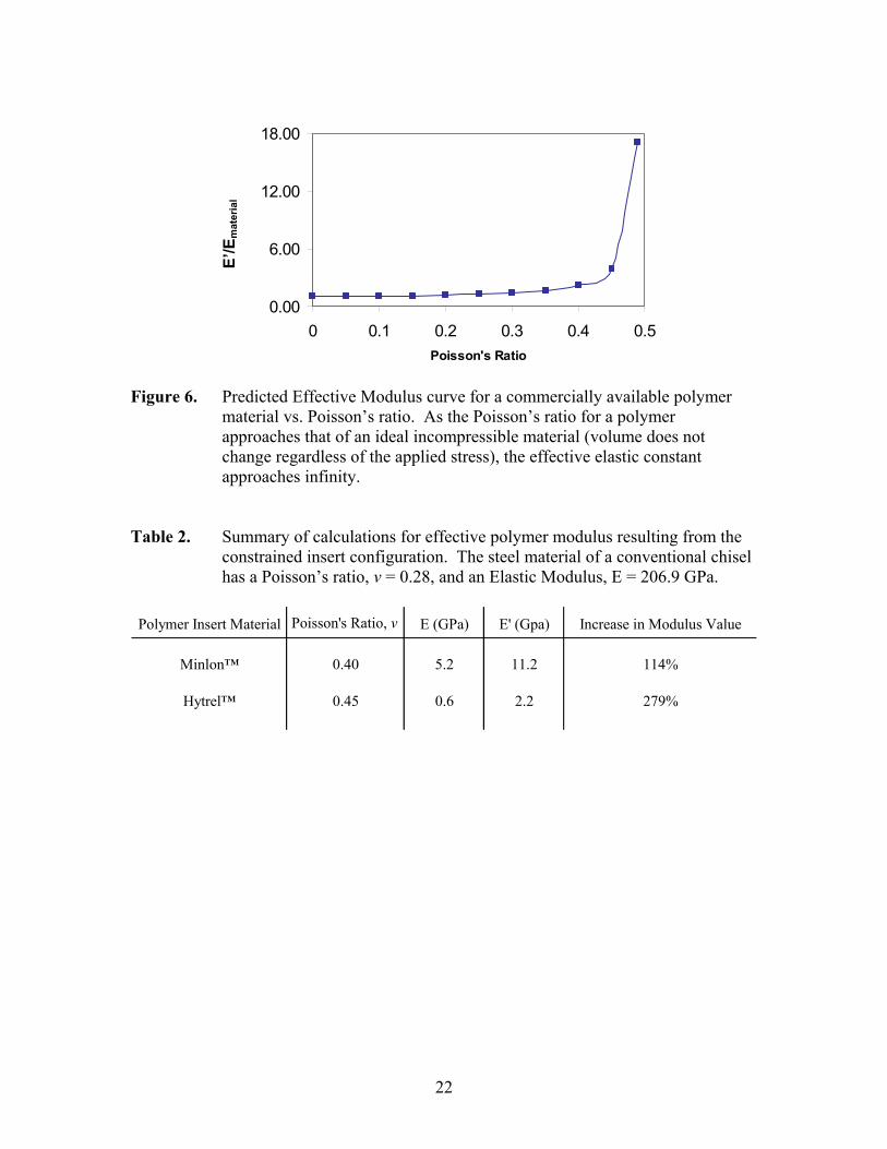
compressed to preserve volume as a result of changing length. Figure 6 shows that
higher Poisson’s ratios demonstrate greater increase in effective modulus as a result of
the constrained insert design. The side chisel walls of the constrained insert
configuration prevent this Poisson’s effect from occurring. Therefore, this constrained
modulus is much larger than Young’s modulus for the simple unconstrained insert
compression when the Poisson effect is free to occur, as illustrated in Table 2. It is
anticipated that the higher apparent modulus of the constrained polymer will provide
significant advantages in terms of force transmission in the tool.
22
0.00
6.00
12.00
18.00
0 0.1 0.2 0.3 0.4 0.5Poisson's Ratio
E'm
ater
ial/E
stee
l
Figure 6. Predicted Effective Modulus curve for a commercially available polymer
material vs. Poisson’s ratio. As the Poisson’s ratio for a polymer approaches that of an ideal incompressible material (volume does not change regardless of the applied stress), the effective elastic constant approaches infinity.
Table 2. Summary of calculations for effective polymer modulus resulting from the constrained insert configuration. The steel material of a conventional chisel has a Poisson’s ratio, v = 0.28, and an Elastic Modulus, E = 206.9 GPa.
Polymer Insert Material Poisson's Ratio, v E (GPa) E' (Gpa) Increase in Modulus Value
Minlon™ 0.40 5.2 11.2 114%
Hytrel™ 0.45 0.6 2.2 279%
E’/E
mat
eria
l

23
Chapter 4
MODELING OF THE FORCE TRANSMISSION CHARACTERISTICS WITH A POLYMER INSERT
4.1 Nomenclature x1 = displacement of piston (from just touching back spring) x2 = displacement of chisel (from just touching “stop”) x3 = velocity of piston x4 = velocity of chisel xa = piston reversal point xi = sharpness parameter tsec = time (sec) m1 = piston mass m2 = effective chisel mass kb = back spring kp = effective spring constant of piston and insert kpa = spring constant of entire piston kpb = spring constant of insert kstop = max stiffness of retaining spring F1 = reaction force on back of piston F2 = compressive force on top of chisel Fp = compressive air force on back of piston Fs = retaining spring force on chisel Fw = reaction force of “work” being cut FR = residual force used to normalize forces (N) L = length used to normalize lengths (m) T = time used to normalize time (sec) y1 = dimensionless force on back of piston y2 = dimensionless force on front of piston yw = dimensionless force on work yp = dimensionless net pressure force on back of piston ys = dimensionless retainer spring force 4.2 Model Development Figure 7 below illustrates the key elements used in the spring-mass model of a reciprocating piston impact tool system.

24
Piston Mass, mp
Pneumatic Force, Fp
Polymer Mass, mpPolymer Stiffness, kp
"Work" Stiffness, kw
Chisel Mass, mcChisel Stiffness, kc
Figure 7. Mass and spring elements used to model the pneumatic tool impact system.
An analysis was made using the following assumptions:
o The force from the air pressure is modeled using the hyperbolic tangent function with the sharpness parameter, xi.
o There is no negative chisel displacement. o Poisson’s ratio is not modeled as time dependent. o Parameter kp is the effective spring constant for the springs in series modeling the
stiffness for the piston and polymer insert components. o No coulomb friction or dampening contributed to energy lost during component
motion and impact. o The mass of the chisel and the spring constant of the work are key parameters in
simulating the chisel force output. o Deformations are linear elastic and kinetic energy is lost to the work, kw, when the
chisel is retracting (chisel velocity is negative). The following were identified as inputs to the model:
o Chisel modulus, top shaft diameter, length, density (steel) o Piston weight, modulus, front diameter, back diameter, length o Insert modulus, Poisson’s ratio, diameter, length, density o Spring constant of work o Compressed air pressure
The outputs of the model were then defined as: o Effective chisel weight
[calculated from chisel and insert density and volume] o Displacement vs. time for the piston o Velocity vs. time for the piston o Output force vs. time for the top of the chisel

25
o Output force vs. time for the bottom of the chisel o Effective polymer spring constant o Effective modulus for the insert o Max force on the top of the insert and the bottom of the chisel
4.3 Mathematical Formulation Using the above definitions and summing the forces acting on each mass, the equations of motion for the piston and chisel are respectively,
PFFxmF −+= 2111 && (11)
SW FFxmF ++= 222 && (12) where the force due to the air pressure is,
( )( )( )ξxaPAFP −= tanh (13) and the contact forces, retaining spring force, and reaction force due to the “work” being cut, respectively, are,
)0,( 11 xkMAXF B−= (14) ( ) )0,( 212 LxxkMAXF P −−= (15)
),( 22 xkFxkMINF RRstopS += (16)
2xkF WW = (17) and the effective spring constant for polymer insert and steel chisel stiffnesses (i.e. two springs in series) is,
PbPa
P
kk
k11
1
+= (18)
Combining the above equations gives the ordinary differential equations for the tool system with the specified boundary conditions,
( ) 0))tanh(( 111
211
1 =+−−−−+ xmkxa
mPALxx
mkx BP ξ&& (19)
)( 2122
22
22 Lxx
mk
mxkF
xmk
x PRRw −−−
+++&& (20)
0)0()0()0()0( 2121 ==== xxxx && (21)
These equations can be normalized for computational simplicity. Defining the following,

26
RkmT /2= (22)
RLkF = (23) FFa R /= (24) FPAb /= (25)
21 / mmc = (26) Lxd a /= (27)
gives the final dimensionless equations that describe the equations of motion of the piston and chisel illustrated in Figure 6,
0121 =−−+ yyyx P&& (28) 022 =−++ yyyx SW&& (29)
0)0()0()0()0( 2121 ==== yyyy && (30) 4.4 Simulation of the Piston and Chisel Motion and Forces
The differential equations were solved in vector matrix form using Matlab™
software. See Appendix A for the complete Matlab™ simulation code. The nonstiff
function ODE45 was used to integrate the system of differential equations y’ = f(t,y)
from time T0 to TFINAL with initial conditions Y0. Each row in the numerical solution
array corresponds to a variable time returned in the column vector T. Most input
parameters were determined by physical measurement. Only two parameters – the
sharpness factor of the hyperbolic function and the ratio of air flow reversal point to total
piston stroke length – were adjusted to ensure complete reciprocating motion of the
piston. The complete set of base case parameters are documented in Table 3.

27
Table 3. Parameter values used in simulations.
Parameter
Piston Weight 93.0 gPiston Diameter 1.89 cmPiston Length 4.60 cmPiston Stroke Length 5.96 cmChisel Top Shaft Diameter 1.01 cmEffective Chisel Length 24.8 cmInsert DiameterInsert LengthSteel Density 1.0E-06 N/m3
Steel Modulus 206.9 GPaMinlon™ 11C40 Density 2.0E-07 N/m3
Minlon™ 11C40 Modulus 5.2 GPaMinlon™ 11C40 Poisson's Ratio 0.40Hytrel™ 7246 Density 1.7E-07 N/m3
Hytrel™ 7246 Modulus 0.57 GPaHytrel™ 7246 Poisson's Ratio 0.45Kr, Retaining Spring Constant 25 kN/mKw, "Work" Spring Constant 87563 kN/mFr, residual spring force 30.6 NCompressed air pressure 621 kPa
Value used in Simulations
Design VariableDesign Variable
By developing and solving the governing equations of motion for the piston-
chisel system, a mathematical simulation has been achieved for use as a design tool. A
number of outputs as a function of time have been computed to characterize the cyclical
nature in terms of position and force output of the tool system. The simplest degree of
validation for the model can be demonstrated without any physical testing of tool
performance. The 56 Hz simulated frequency for the piston in the conventional tool
system closely matches the 58 Hz frequency rating provided in the tool manufacturer’s
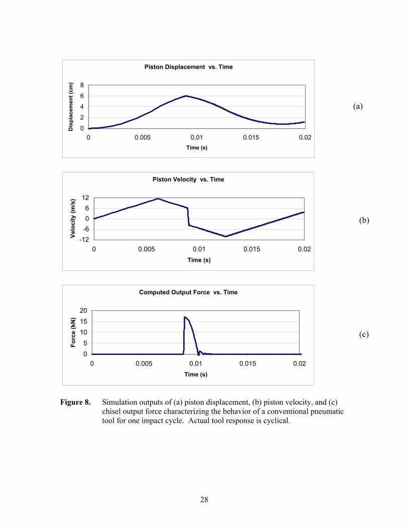
product specification literature. Figures 8a through 8c are typical time graphs of
simulation outputs for one impact cycle with the prototype chisel.
28
Piston Displacement vs. Time
0
2
4
6
8
0 0.005 0.01 0.015 0.02Time (s)
Dis
plac
emen
t (cm
)
Piston Velocity vs. Time
-12-606
12
0 0.005 0.01 0.015 0.02Time (s)
Velo
city
(m/s
)
Computed Output Force vs. Time
05
101520
0 0.005 0.01 0.015 0.02Time (s)
Forc
e (k
N)
Figure 8. Simulation outputs of (a) piston displacement, (b) piston velocity, and (c)
chisel output force characterizing the behavior of a conventional pneumatic tool for one impact cycle. Actual tool response is cyclical.
(a)
(b)
(c)

29
As the piston makes its forward stroke down the tool chamber, the chisel remains in
a fixed position. At maximum piston displacement, there is a spike in the chisel output
displacement and force due to the impact between the piston and chisel. Following this
collision, the piston reverses direction and the chisel moves back as the retaining spring
retrieves the chisel to its original position. The plot of piston velocity also demonstrates
the sudden directional change of the piston (positive to negative velocity) upon impact
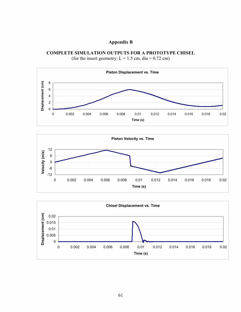
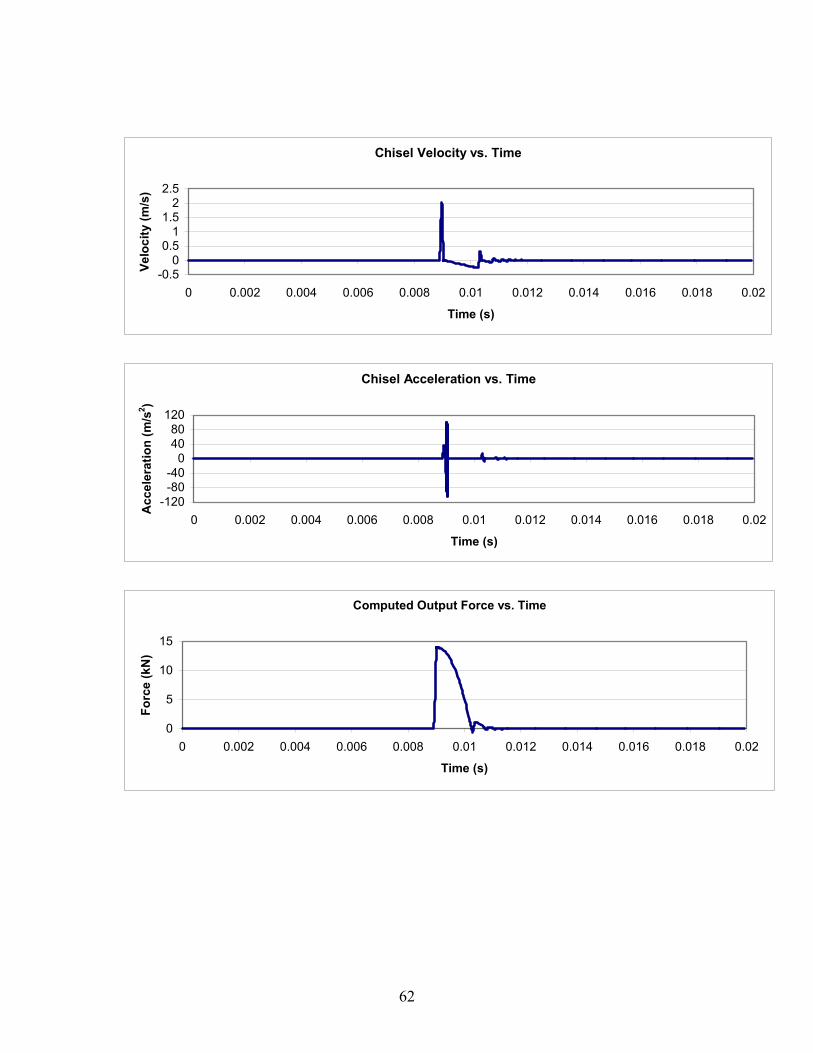
with the chisel. See Appendix B for complete simulation outputs as a function of time
for a prototype chisel with a polymer insert.
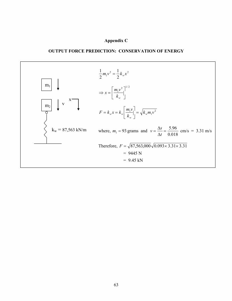
In addition to Matlab™ simulations, calculations based upon the conservation of
energy and impulse momentum theorems provided further supporting evidence to make a
strong order of magnitude prediction for the tool output force. See Appendix C and
Appendix D for complete documentation of each computation, respectively. The results
of this analysis support the simulation results by estimating the chisel output force on the
order of 10 kN.
4.5 Prediction of Chisel Cutting Force During an Impact
Table 4 summarizes the results of simulated force for the top and the bottom of
the chisel. In each case, the forces shown are for both a conventional chisel and a chisel
with a polymer insert. The force on the bottom is most relevant since it is the force
actually cutting into the work. The slight difference seen in the simulated force values
between the top and bottom of the chisel demonstrates the effect of the chisel inertia.
While chisel inertia slightly reduces predicted values of force transmission between the
top and bottom of the chisel in both scenarios, the maximum chisel forces for the

30
conventional chisel are only slightly higher than the forces predicted for the chisel with a
constrained Minlon™ polymer insert. Force vs. time is plotted on Figure 9 for the force
at the bottom of the chisel.
Table 4. Summary of maximum predicted forces for various chisel configurations.
For the chisels with a polymer insert, the insert has been modeled with a geometry of L = 1.5 centimeters and d = 0.72 centimeters.
Chisel Treatment Force at Top of Chisel (kN) Force at Bottom of Chisel (kN)
Conventional Steel Chisel 17.00 16.99
Chisel with Minlon™ Insert 14.11 13.92
Chisel with Hytrel™ Insert 6.18 6.08
02468
1012141618
0 0.002 0.004 0.006 0.008 0.01 0.012 0.014 0.016 0.018 0.02Time (s)
Forc
e (k
N)
Figure 9. Predicted force vs. time graphs for the force at the bottom of a
conventional chisel and a chisel with a polymer insert. 4.6 Effect of Polymer Material Properties on Maximum Output Force
Maximum chisel force is the key parameter for tool performance, therefore, the
polymer modulus-force relation has been examined. Higher modulus polymers yield
Conventional Chisel Chisel with a Minlon™ Insert
31
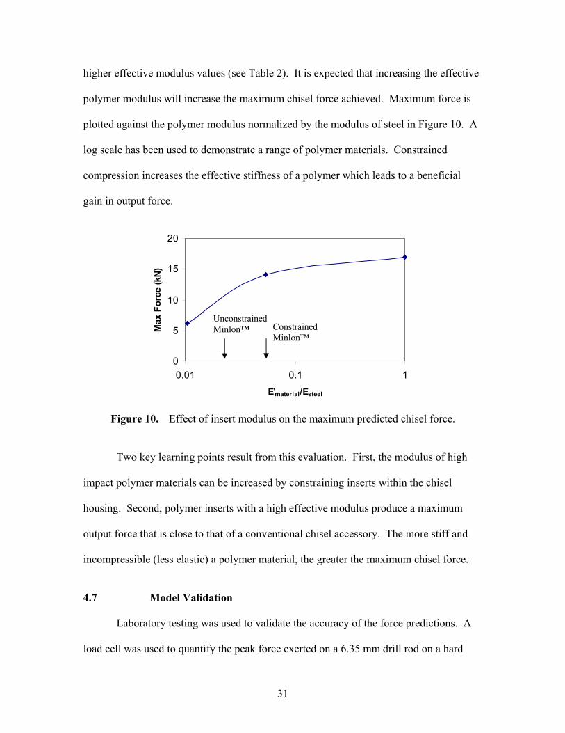
higher effective modulus values (see Table 2). It is expected that increasing the effective
polymer modulus will increase the maximum chisel force achieved. Maximum force is
plotted against the polymer modulus normalized by the modulus of steel in Figure 10. A
log scale has been used to demonstrate a range of polymer materials. Constrained
compression increases the effective stiffness of a polymer which leads to a beneficial
gain in output force.
0
5
10
15
20
0.01 0.1 1
E'material/Esteel
Max
For
ce (k
N)
Figure 10. Effect of insert modulus on the maximum predicted chisel force.
Two key learning points result from this evaluation. First, the modulus of high
impact polymer materials can be increased by constraining inserts within the chisel
housing. Second, polymer inserts with a high effective modulus produce a maximum
output force that is close to that of a conventional chisel accessory. The more stiff and
incompressible (less elastic) a polymer material, the greater the maximum chisel force.
4.7 Model Validation Laboratory testing was used to validate the accuracy of the force predictions. A
load cell was used to quantify the peak force exerted on a 6.35 mm drill rod on a hard
Constrained Minlon™
Unconstrained Minlon™

32
surface by the cutting tool. Table 5 compares the predicted maximum output force
exerted by the chisel to the measured value of force. The measured values of force for
both a conventional chisel and a chisel with a polymer insert are similar to the simulation
results. As expected, the mean value results show that a polymer insert reduces chisel
force, however, this reduction was found to be statistically insignificant (at the 95%
confidence level).
Table 5. Summary of predicted and measured force exerted on the test specimen by
the chisel. There was a small but statistically insignificant decrease in measured force output for a prototype chisel when compared to the output force value for a conventional chisel.
from Matlab™ Lower 95% Bound Mean Upper 95% Bound
Conventional Steel Chisel 16.99 14.94 16.1 17.28
Chisel with a Minlon™ Insert 13.92 10.68 14.3 17.83
Measured Force (N)Predicted Force (N)Treatment
4.8 Effect of Insert Diameter and Insert Length
Increasing polymer stiffness certainly increases chisel force. For the conventional
chisel system, the model predicted a maximum output force of 17 kN. The model can
also be used to optimize the chisel and a polymer insert geometries, particularly with
respect to the choice parameters of insert length and insert diameter to achieve desirable
chisel forces. From Equation 1, it is expected that polymer stiffness can be improved by
increasing insert diameter (which increases cross sectional area). It is also anticipated
from the stiffness equation that increasing insert length reduces insert stiffness.
(kN) (kN)
33
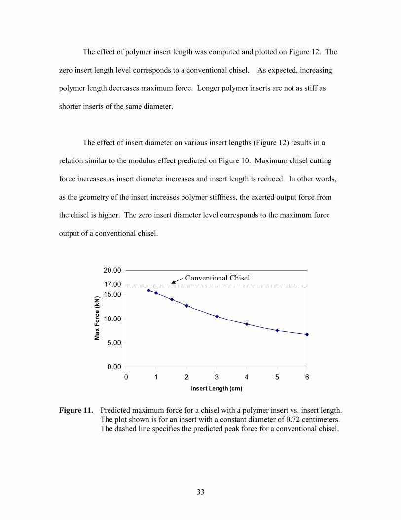
The effect of polymer insert length was computed and plotted on Figure 12. The
zero insert length level corresponds to a conventional chisel. As expected, increasing
polymer length decreases maximum force. Longer polymer inserts are not as stiff as
shorter inserts of the same diameter.
The effect of insert diameter on various insert lengths (Figure 12) results in a
relation similar to the modulus effect predicted on Figure 10. Maximum chisel cutting
force increases as insert diameter increases and insert length is reduced. In other words,
as the geometry of the insert increases polymer stiffness, the exerted output force from
the chisel is higher. The zero insert diameter level corresponds to the maximum force
output of a conventional chisel.
0.00
5.00
10.00
15.00
20.00
0 1 2 3 4 5 6Insert Length (cm)
Max
For
ce (k
N)
Figure 11. Predicted maximum force for a chisel with a polymer insert vs. insert length. The plot shown is for an insert with a constant diameter of 0.72 centimeters. The dashed line specifies the predicted peak force for a conventional chisel.
17.00 Conventional Chisel

34
Figure 12. Predicted effect of insert diameter and length on maximum chisel force of a
chisel with a polymer insert. The predicted maximum output force for a conventional chisel is indicated by the dashed line.
0.00
5.00
10.00
15.00
20.00
0.000 0.200 0.400 0.600 0.800 1.000Insert Diameter (cm)
Max
For
ce (k
N)
1.5
L = 0.75 cm
1.0
3.0
6.0
17.00 Conventional Chisel

35
Chapter 5
DURABILITY AND PERFORMANCE TESTING
In this chapter, two methods of testing are described. Laboratory testing using an
Instron™ test machine is performed to artificially aged the polymer insert with repeated
loading cycles. Test results are used to confirm the effective modulus of the insert and
understand the life-load behavior (i.e. the durability) of the polymer insert. In addition,
field (human) trials in which a pneumatic chisel equipped with a chisel and polymer
insert are conducted to measure the vibration and sound emission characteristics of the
prototype tool.
5.1 Methodology for Insert Material Integrity Testing
High frequency Instron™ testing was used to reproduce controlled impact cycles
for laboratory testing and observation of chisel prototype behavior. The specific
objectives of the testing were to determine force transmission and polymer degradation as
a function of the number of impact cycles at comparable loads applied to the chisel
accessory in the running tool. Characterizing the fatigue life of materials is dependent
upon the damage of cumulative cycles, not the frequency of the loading. Therefore, the
frequency of impact is a secondary test parameter to the desired load and number of
cycles to be applied during testing.
Prototype chisels were mounted in an Instron™ hydraulic test machine shown in
Figure 13 for artificial aging due to cyclical loading. The top portion of the prototype
chisel is exposed when mounted for testing. The testing machine applied a regular
36
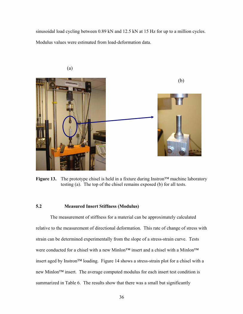
sinusoidal load cycling between 0.89 kN and 12.5 kN at 15 Hz for up to a million cycles.
Modulus values were estimated from load-deformation data.
Figure 13. The prototype chisel is held in a fixture during Instron™ machine laboratory
testing (a). The top of the chisel remains exposed (b) for all tests. 5.2 Measured Insert Stiffness (Modulus)
The measurement of stiffness for a material can be approximately calculated
relative to the measurement of directional deformation. This rate of change of stress with
strain can be determined experimentally from the slope of a stress-strain curve. Tests
were conducted for a chisel with a new Minlon™ insert and a chisel with a Minlon™
insert aged by Instron™ loading. Figure 14 shows a stress-strain plot for a chisel with a
new Minlon™ insert. The average computed modulus for each insert test condition is
summarized in Table 6. The results show that there was a small but significantly
(a)
(b)

37
insignificant increase (at the 95% confidence interval) in the insert stiffness for the
artificially aged insert. Photographs of the top of the chisel with a polymer insert prior to
Instron preloading and after Instron preloading are shown in Figure 15.
00.050.1
0.150.2
0.250.3
0.35
0 0.01 0.02 0.03 0.04Strain (in/in)
Stre
ss (G
Pa)
Figure 14. Typical stress-strain graph of new Minlon™ insert. Processing for an average modulus (stiffness) value was achieved by computing the slope of a trendline for the middle two-thirds of collected data.
Table 6. Summary of measured polymer insert modulus values for 10 trials.
Averages and the range of responses are given.
New Insert Preloaded Insert
Modulus Value (GPa) 6.94 6.86(6.27 to 7.24) (5.83 to 7.52)
a a
38
(a) (b)
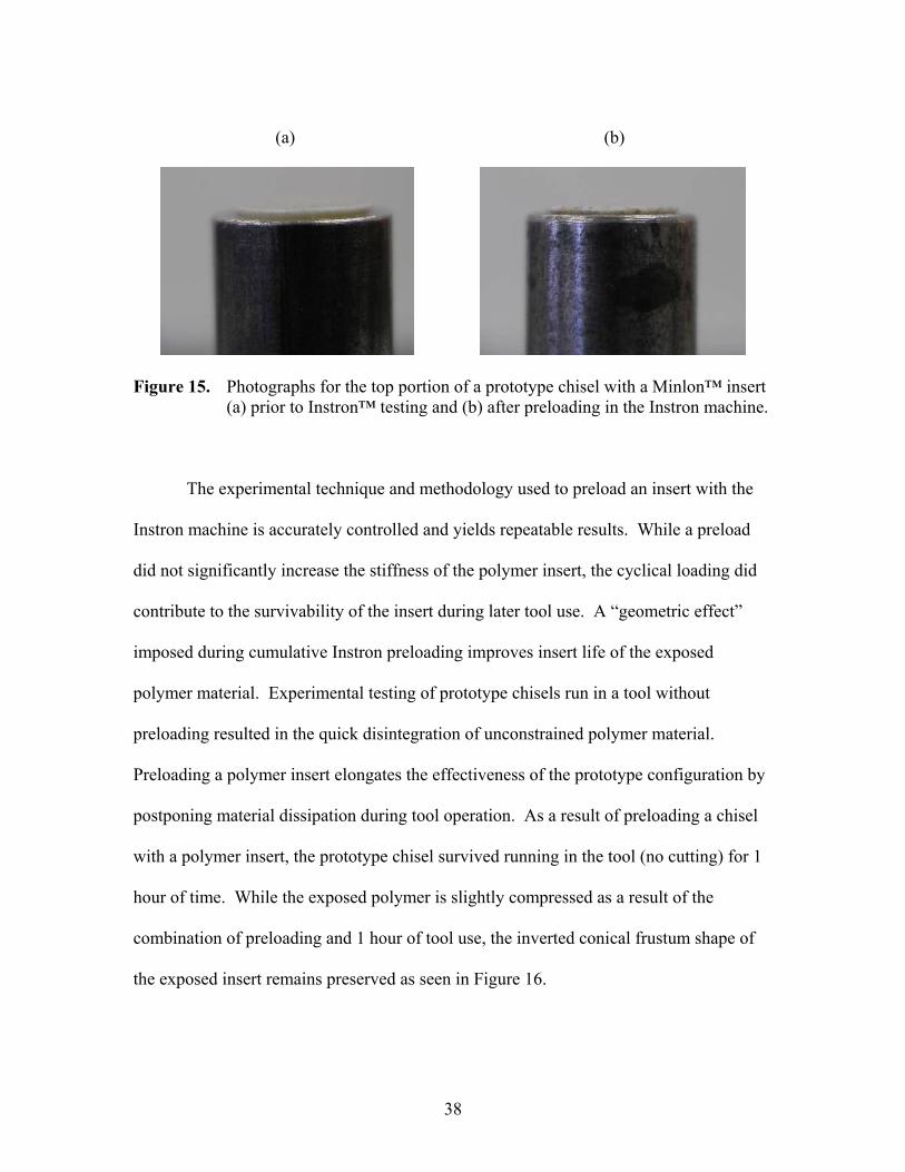
Figure 15. Photographs for the top portion of a prototype chisel with a Minlon™ insert
(a) prior to Instron™ testing and (b) after preloading in the Instron machine.
The experimental technique and methodology used to preload an insert with the
Instron machine is accurately controlled and yields repeatable results. While a preload
did not significantly increase the stiffness of the polymer insert, the cyclical loading did
contribute to the survivability of the insert during later tool use. A “geometric effect”
imposed during cumulative Instron preloading improves insert life of the exposed
polymer material. Experimental testing of prototype chisels run in a tool without
preloading resulted in the quick disintegration of unconstrained polymer material.
Preloading a polymer insert elongates the effectiveness of the prototype configuration by
postponing material dissipation during tool operation. As a result of preloading a chisel
with a polymer insert, the prototype chisel survived running in the tool (no cutting) for 1
hour of time. While the exposed polymer is slightly compressed as a result of the
combination of preloading and 1 hour of tool use, the inverted conical frustum shape of
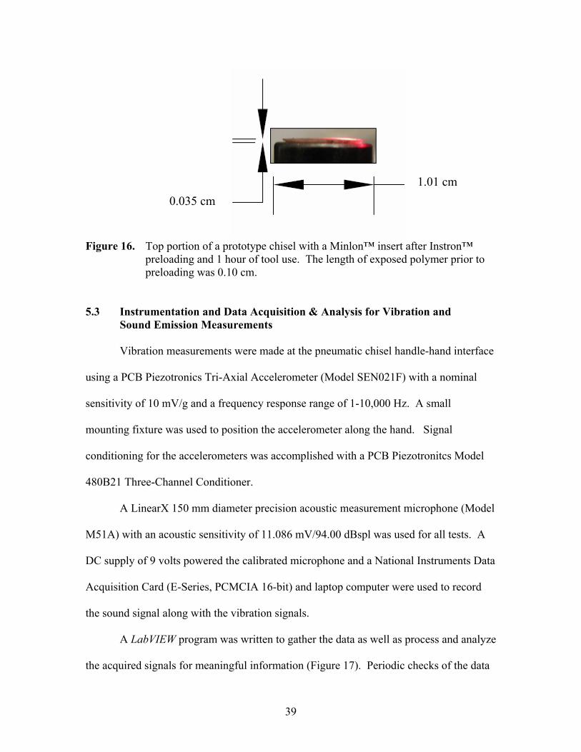
the exposed insert remains preserved as seen in Figure 16.
39
Figure 16. Top portion of a prototype chisel with a Minlon™ insert after Instron™
preloading and 1 hour of tool use. The length of exposed polymer prior to preloading was 0.10 cm.
5.3 Instrumentation and Data Acquisition & Analysis for Vibration and
Sound Emission Measurements
Vibration measurements were made at the pneumatic chisel handle-hand interface
using a PCB Piezotronics Tri-Axial Accelerometer (Model SEN021F) with a nominal
sensitivity of 10 mV/g and a frequency response range of 1-10,000 Hz. A small
mounting fixture was used to position the accelerometer along the hand. Signal
conditioning for the accelerometers was accomplished with a PCB Piezotronitcs Model
480B21 Three-Channel Conditioner.
A LinearX 150 mm diameter precision acoustic measurement microphone (Model
M51A) with an acoustic sensitivity of 11.086 mV/94.00 dBspl was used for all tests. A
DC supply of 9 volts powered the calibrated microphone and a National Instruments Data
Acquisition Card (E-Series, PCMCIA 16-bit) and laptop computer were used to record
the sound signal along with the vibration signals.
A LabVIEW program was written to gather the data as well as process and analyze
the acquired signals for meaningful information (Figure 17). Periodic checks of the data
1.01 cm 0.035 cm

40
acquisition and signal processing system were accomplished with several different tone
sources: a perfect “E” note tuning fork (329 Hz), and two Projects Unlimited continuous
tone piezoelectric audio indicators (2800 and 4500 Hz).
Data was manipulated and analyzed in order to extract desired information and
obtain results from the time domain signal acquired using the hardware and LabVIEW
program. Fast Fourier Transforms were preformed on sound vs. time and acceleration vs.
time data sets to determine and identify dominant components in the frequency domain.
Figure 17. LabVIEW interface for the data acquisition and processing program used to
collect and analyze the sound and vibration data.
In order to obtain peak decibel output readings, an exponential averaging
technique was utilized. The averaged level of the sound pressure signal (measured in
units of Pascal) was computed based on an exponential mode after each sample of time
and returned as an exponential averaged sound level in decibels. Selecting a custom
exponential time constant of 125 milliseconds allowed for the continuous running
41
average to accurately capture a short duration impulsive signal. Discrete Fourier
transforms of the sound pressure and acceleration were performed using the following
form:
∑−
=
=1
0
/2)(N
k
Nnkin enfF π (4)
where, Fn = Fourier transform
f(n) = nth measured time domain data N = Number of data
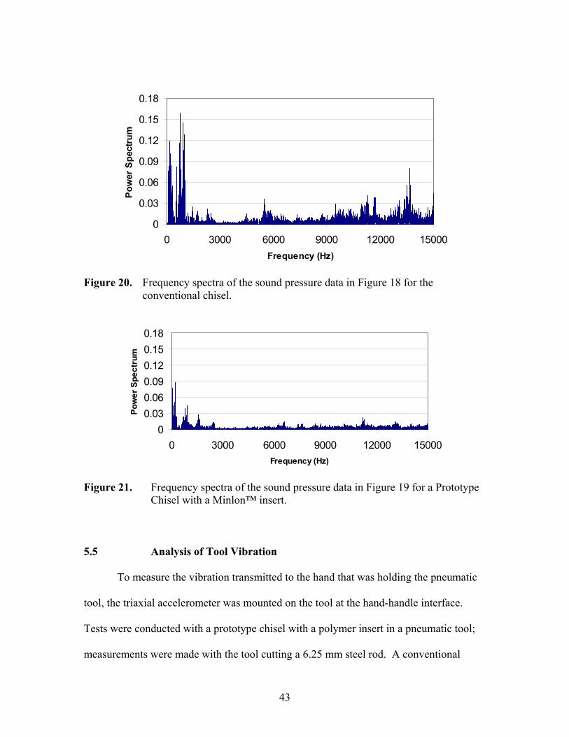
5.4 Analysis of Tool Sound Emission
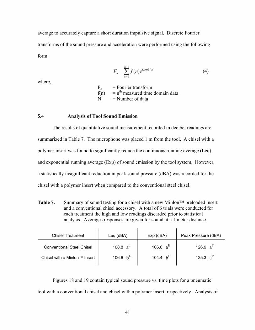
The results of quantitative sound measurement recorded in decibel readings are
summarized in Table 7. The microphone was placed 1 m from the tool. A chisel with a
polymer insert was found to significantly reduce the continuous running average (Leq)
and exponential running average (Exp) of sound emission by the tool system. However,
a statistically insignificant reduction in peak sound pressure (dBA) was recorded for the
chisel with a polymer insert when compared to the conventional steel chisel.
Table 7. Summary of sound testing for a chisel with a new Minlon™ preloaded insert
and a conventional chisel accessory. A total of 6 trials were conducted for each treatment the high and low readings discarded prior to statistical analysis. Averages responses are given for sound at a 1 meter distance.
Chisel Treatment Leq (dBA) Exp (dBA) Peak Pressure (dBA)
Conventional Steel Chisel 108.8 106.6 126.9
Chisel with a Minlon™ Insert 106.6 104.4 125.3
Figures 18 and 19 contain typical sound pressure vs. time plots for a pneumatic
tool with a conventional chisel and chisel with a polymer insert, respectively. Analysis of
aL bL
aE bE
aP aP

42
the frequency content of these signals as illustrated in Figures 20 and 21 suggests that a
chisel with a polymer insert reduces the sound emitted by a pneumatic chisel across the
frequency spectra, including harmful high-frequency noise.
-40-30-20-10
010203040
0 0.2 0.4 0.6 0.8 1Time (s)
Soun
d Pr
essu
re (P
a)
Figure 18. Typical time domain response of sound for a conventional chisel.
-40-30-20-10
010203040
0 0.2 0.4 0.6 0.8 1Time (s)
Soun
d Pr
essu
re (P
a)
Figure 19. Typical time domain response of sound for a prototype chisel with a
Minlon™ insert.
43
0
0.03
0.06
0.09
0.12
0.15
0.18
0 3000 6000 9000 12000 15000Frequency (Hz)
Pow
er S
pect
rum
Figure 20. Frequency spectra of the sound pressure data in Figure 18 for the
conventional chisel.
00.030.060.090.120.150.18
0 3000 6000 9000 12000 15000Frequency (Hz)
Pow
er S
pect
rum
Figure 21. Frequency spectra of the sound pressure data in Figure 19 for a Prototype
Chisel with a Minlon™ insert.
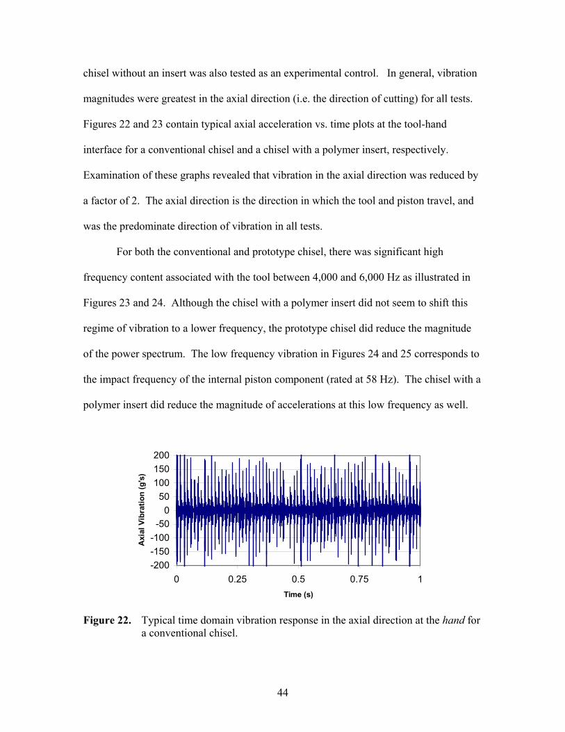
5.5 Analysis of Tool Vibration
To measure the vibration transmitted to the hand that was holding the pneumatic
tool, the triaxial accelerometer was mounted on the tool at the hand-handle interface.
Tests were conducted with a prototype chisel with a polymer insert in a pneumatic tool;
measurements were made with the tool cutting a 6.25 mm steel rod. A conventional
44
chisel without an insert was also tested as an experimental control. In general, vibration
magnitudes were greatest in the axial direction (i.e. the direction of cutting) for all tests.
Figures 22 and 23 contain typical axial acceleration vs. time plots at the tool-hand
interface for a conventional chisel and a chisel with a polymer insert, respectively.
Examination of these graphs revealed that vibration in the axial direction was reduced by
a factor of 2. The axial direction is the direction in which the tool and piston travel, and
was the predominate direction of vibration in all tests.
For both the conventional and prototype chisel, there was significant high
frequency content associated with the tool between 4,000 and 6,000 Hz as illustrated in
Figures 23 and 24. Although the chisel with a polymer insert did not seem to shift this
regime of vibration to a lower frequency, the prototype chisel did reduce the magnitude
of the power spectrum. The low frequency vibration in Figures 24 and 25 corresponds to
the impact frequency of the internal piston component (rated at 58 Hz). The chisel with a
polymer insert did reduce the magnitude of accelerations at this low frequency as well.
-200-150-100
-500
50100150200
0 0.25 0.5 0.75 1Time (s)
Axi
al V
ibra
tion
(g's
)
Figure 22. Typical time domain vibration response in the axial direction at the hand for
a conventional chisel.

45
-200-150-100
-500
50100150200
0 0.25 0.5 0.75 1Time (s)
Axi
al V
ibra
tion
(g's
)
Figure 23. Typical time domain vibration response in the axial direction at the hand for
a prototype chisel with a Minlon™ insert.
00.20.40.60.8
11.21.4
0 2000 4000 6000 8000 10000
Frequency (Hz)
Pow
er S
pect
rum
Figure 24. Overall frequency content of the data in Figure 22 for a conventional chisel.
00.20.40.60.8
11.21.4
0 2000 4000 6000 8000 10000Frequency (Hz)
Pow
er S
pect
rum
Figure 25. Overall frequency content of the data in Figure 23 for a prototype chisel
with a Minlon™ insert.
46
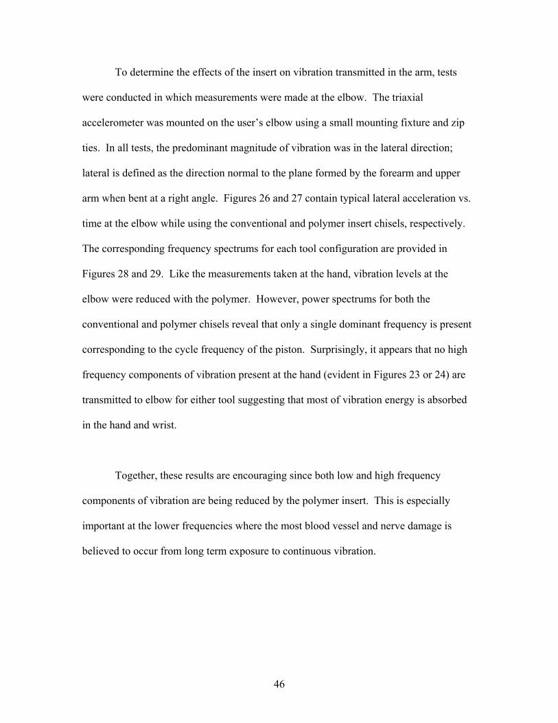
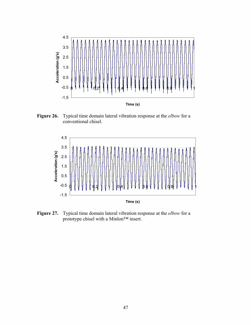
To determine the effects of the insert on vibration transmitted in the arm, tests
were conducted in which measurements were made at the elbow. The triaxial
accelerometer was mounted on the user’s elbow using a small mounting fixture and zip
ties. In all tests, the predominant magnitude of vibration was in the lateral direction;
lateral is defined as the direction normal to the plane formed by the forearm and upper
arm when bent at a right angle. Figures 26 and 27 contain typical lateral acceleration vs.
time at the elbow while using the conventional and polymer insert chisels, respectively.
The corresponding frequency spectrums for each tool configuration are provided in
Figures 28 and 29. Like the measurements taken at the hand, vibration levels at the
elbow were reduced with the polymer. However, power spectrums for both the
conventional and polymer chisels reveal that only a single dominant frequency is present
corresponding to the cycle frequency of the piston. Surprisingly, it appears that no high
frequency components of vibration present at the hand (evident in Figures 23 or 24) are
transmitted to elbow for either tool suggesting that most of vibration energy is absorbed
in the hand and wrist.
Together, these results are encouraging since both low and high frequency
components of vibration are being reduced by the polymer insert. This is especially
important at the lower frequencies where the most blood vessel and nerve damage is
believed to occur from long term exposure to continuous vibration.
47
-1.5
-0.5
0.5
1.5
2.5
3.5
4.5
0 0.2 0.4 0.6 0.8 1
Time (s)
Acc
eler
atio
n (g
's)
Figure 26. Typical time domain lateral vibration response at the elbow for a
conventional chisel.
-1.5
-0.5
0.5
1.5
2.5
3.5
4.5
0 0.2 0.4 0.6 0.8 1
Time (s)
Acc
eler
atio
n (g
's)
Figure 27. Typical time domain lateral vibration response at the elbow for a
prototype chisel with a Minlon™ insert.

48
0
0.4
0.8
1.2
1.6
0 20 40 60 80 100
Frequency (Hz)
Pow
er S
pect
rum
Figure 28. Overall frequency content of the data in Figure 26 for a conventional chisel.
0
0.4
0.8
1.2
1.6
0 20 40 60 80 100
Frequency (Hz)
Pow
er S
pect
rum
Figure 29. Overall frequency content of the data in Figure 27 for a prototype chisel
with a Minlon™ insert.

49
Chapter 6
CONCLUSIONS & RECOMMENDED PATH FORWARD 6.1 General Discussion
Hand-arm vibration is a complex hazard resulting from a combination of
environmental, individual, and ergonomic factors. Powered hand tools create an
occupational risk for biomechanical injuries to many workers throughout the world
whose jobs require frequent and continuous use of these devices. While administrative
regulations, work practices, and personal protective equipment have been use to reduce
the potential for some of the detrimental effects resulting from tool use, engineering
controls and improved tool designs should be examined.
In light of the problems associated with the use of powered hand tools, a new
chisel accessory design incorporating a reinforced polymer insert was investigated. A
lumped-parameter model was used to simulate tool system behavior and compute force
transmission characteristics of the new chisel design. Laboratory testing was also
conducted to validate the model and quantify potential performance benefits in sound and
vibration reduction resulting from a prototype chisel with a polymer insert.
6.2 Conclusions
Based on the results presented and analyzed in the study, the following
conclusions have been made:

50
1. A mathematical simulation of the piston-chisel system has been developed and
validated using first order differential equations.
2. Constraining and aging an insert as a function of the number of loading cycles
increases the effective polymer modulus, E’.
3. Preloading a chisel with a polymer insert did not significantly increase insert
stiffness, however, an increase in stiffness can be achieved through optimization of
insert geometry (length, diameter).
4. Flexural modulus and Poisson’s ratio of a polymer significantly effect force
transmission characteristics of a chisel insert.
5. Predicted forces at the bottom of a chisel are similar to the experimentally measured
chisel output forces. A polymer insert slightly reduces chisel force, however this
reduction was found to be statistically insignificant at the 95% confidence level.
6. Prototype chisels with a Minlon™ insert significantly reduced the continuous running
average of tool sound emission and decreased the magnitude of vibration transmitted
to the hand by a factor of 2.
7. The use of polymers in power tool designs has the potential to reduce biomechanical
injury and Hand-Arm Vibration related ailments to tool users. Specifically, the
significant reductions in vibration, especially at lower frequencies where blood vessel
and nerve damage is believed to occur, indicate the long term use of these new tools
will likely prevent or delay the onset of vascular and nerve damage in the hand and
arm if used properly.
8. Prototype chisels with a polymer insert have survived over 1 hour of field testing.

51
6.3 Suggestions for Future Work
The parameters of flexural modulus and Poisson’s ratio effect the selection of an
appropriate reinforced polymer for a chisel insert. Constraining a polymer insert created
a hydrostatic compressive loading condition on the insert, thus increasing its apparent
modulus of elasticity and improving its force transmission characteristics. While no
significant increase in measured stiffness resulted from preloading of the chisel with a
polymer insert prototype, hardening of the polymer from compressive impact loading was
found to increase the durability of the exposed polymer insert material during actual tool
operation.
The incorporation of a constrained polymer insert to chisel design prevents metal-
to-metal impact between the piston and chisel components in power tool systems.
Clearly, conventional chisel accessories produce high levels of sound that could damage
the ear along with magnitudes and frequencies of vibration that contribute to
biomechanical injuries over time. Prototype chisels have attenuated both sound and
vibration emissions from the power tool system. While chisels with a polymer insert
have survived over 1 hour of time in a running tool, more testing is needed to confirm the
cutting effectiveness and durability of the new chisel systems.
Optimization of insert geometry for stiffness and durability will improve the
transmission of impact energy. To further evaluate force transmission characteristics,
finite element modeling should be completed for the conventional chisel as well as both
constrained and unconstrained polymer inserts designs. Additionally, the relationship

52
between original protrusion length and desired preload applied to a prototype chisel prior
to running in a tool should be investigated. The combination of these two variables and
the correlation to prototype chisel durability and life has not been examined in enough
detail to propose a final insert geometry and preloading specification at this time.
Finally, the constrained configuration of the insert within the chisel housing was
proven to increase force transmission. The unique inverted conical frustum shape of the
protruding polymer material resulting from the interference fit between the cylindrical
insert and side chisel walls should be examined for similar performance advantages.
53
REFERENCES
[1] United States Department of Labor, Bureau of Labor Statistics, (2004). Table R27:
Detailed Source of Selected Events and Exposures. Available online:
http://www.bls.gov/iif/oshwc/osh/case/ostb1537.pdf (accessed April 2, 2006).
[2] United States Navy, Navy Safety Center. Acquisition Safety Vibration. Available
online: http://www.safetycenter.navy.mil/acquisition/vibration/default.htm
(accessed April 2, 2006).
[3] United States Department of Labor, Occupational Safety and Health Administration,
(2000). Ergonomics Rules: OSHA’s Final Ergonomics Standard.
http://www.spineuniverse.com/displayarticle.php/article1405.html (accessed April
2, 2006).
[4] Glancey, J.L., J. Moore, D. Muhlenforth, J. Lawrence, (2004). Measurement of
Manual and Power Impact Tool Vibration Transmission to the Hand. Paper
No.047027. Written for Presentation at the 2004 ASAE/CSAE Annual
International Meeting, Ottawa, Ontario, Canada.
[5] Glancey, J.L., P. Popper (Dupont), T. Nasr, P. Truitt, M. Orgovan, D. O’Brian,
(2003). Design and Performance of Hand-Struck Impact Tools Using High

54
Performance Engineering Polymers. Paper No. IMECE2003-41455. Proceedings
of the 2003 ASME International Annual meeting, Washington, D.C.
[6] The Dupont Company, Plastics Homepage. Americas Data Sheets.
http://plastics.dupont.com/NASApp/myplastics/Mediator?id=0 (accessed January
4, 2006).
55
Appendix A
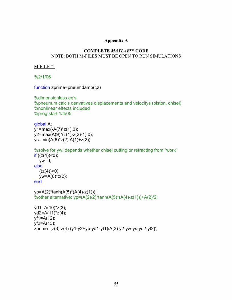
COMPLETE MATLAB™ CODE NOTE: BOTH M-FILES MUST BE OPEN TO RUN SIMULATIONS
M-FILE #1 %2/1/06 function zprime=pneumdamp(t,z) %dimensionless eq's %pneum.m calc's derivatives displacements and velocitys (piston, chisel) %nonlinear effects included %prog start 1/4/05 global A; y1=max(-A(7)*z(1),0); y2=max(A(9)*(z(1)-z(2)-1),0); ys=min(A(6)*z(2),A(1)+z(2)); %solve for yw; depends whether chisel cutting or retracting from "work" if ((z(4))<0); yw=0; else ((z(4))>0); yw=A(8)*z(2); end yp=A(2)*tanh(A(5)*(A(4)-z(1))); %other alternative: yp=(A(2)/2)*tanh(A(5)*(A(4)-z(1)))+A(2)/2; yd1=A(10)*z(3); yd2=A(11)*z(4); yf1=A(12); yf2=A(13); zprime=[z(3) z(4) (y1-y2+yp-yd1-yf1)/A(3) y2-yw-ys-yd2-yf2]';
56
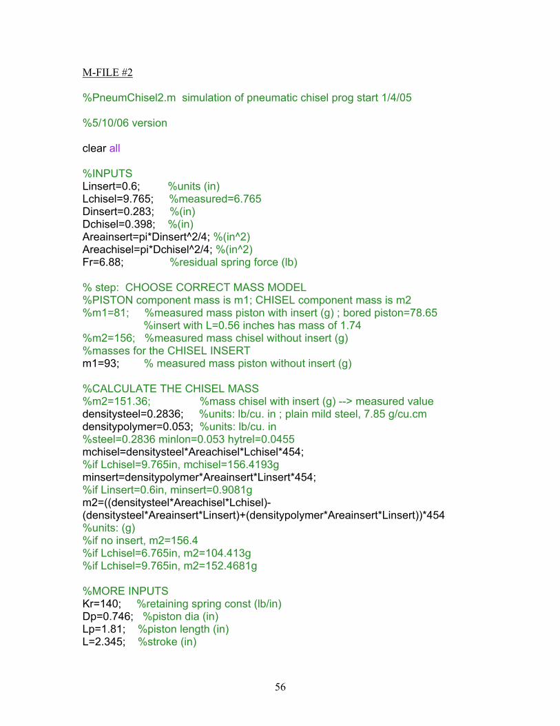
M-FILE #2 %PneumChisel2.m simulation of pneumatic chisel prog start 1/4/05 %5/10/06 version clear all %INPUTS Linsert=0.6; %units (in) Lchisel=9.765; %measured=6.765 Dinsert=0.283; %(in) Dchisel=0.398; %(in) Areainsert=pi*Dinsert^2/4; %(in^2) Areachisel=pi*Dchisel^2/4; %(in^2) Fr=6.88; %residual spring force (lb) % step: CHOOSE CORRECT MASS MODEL %PISTON component mass is m1; CHISEL component mass is m2 %m1=81; %measured mass piston with insert (g) ; bored piston=78.65 %insert with L=0.56 inches has mass of 1.74 %m2=156; %measured mass chisel without insert (g) %masses for the CHISEL INSERT m1=93; % measured mass piston without insert (g) %CALCULATE THE CHISEL MASS %m2=151.36; %mass chisel with insert (g) --> measured value densitysteel=0.2836; %units: lb/cu. in ; plain mild steel, 7.85 g/cu.cm densitypolymer=0.053; %units: lb/cu. in %steel=0.2836 minlon=0.053 hytrel=0.0455 mchisel=densitysteel*Areachisel*Lchisel*454; %if Lchisel=9.765in, mchisel=156.4193g minsert=densitypolymer*Areainsert*Linsert*454; %if Linsert=0.6in, minsert=0.9081g m2=((densitysteel*Areachisel*Lchisel)-(densitysteel*Areainsert*Linsert)+(densitypolymer*Areainsert*Linsert))*454 %units: (g) %if no insert, m2=156.4 %if Lchisel=6.765in, m2=104.413g %if Lchisel=9.765in, m2=152.4681g %MORE INPUTS Kr=140; %retaining spring const (lb/in) Dp=0.746; %piston dia (in) Lp=1.81; %piston length (in) L=2.345; %stroke (in)
57
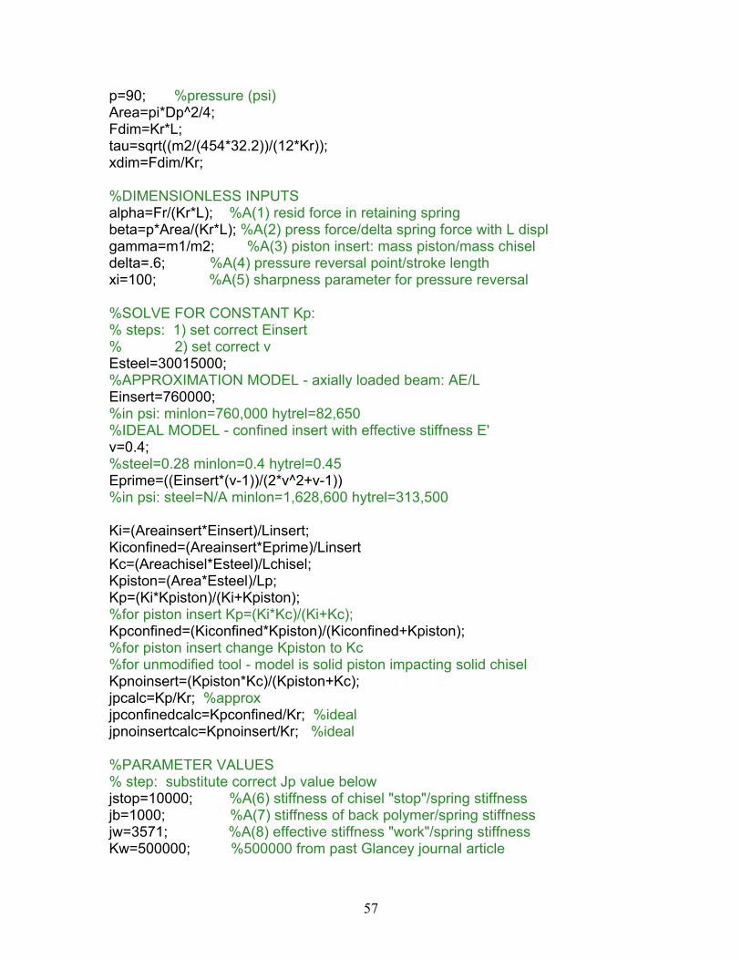
p=90; %pressure (psi) Area=pi*Dp^2/4; Fdim=Kr*L; tau=sqrt((m2/(454*32.2))/(12*Kr)); xdim=Fdim/Kr; %DIMENSIONLESS INPUTS alpha=Fr/(Kr*L); %A(1) resid force in retaining spring beta=p*Area/(Kr*L); %A(2) press force/delta spring force with L displ gamma=m1/m2; %A(3) piston insert: mass piston/mass chisel delta=.6; %A(4) pressure reversal point/stroke length xi=100; %A(5) sharpness parameter for pressure reversal %SOLVE FOR CONSTANT Kp: % steps: 1) set correct Einsert % 2) set correct v Esteel=30015000; %APPROXIMATION MODEL - axially loaded beam: AE/L Einsert=760000; %in psi: minlon=760,000 hytrel=82,650 %IDEAL MODEL - confined insert with effective stiffness E' v=0.4; %steel=0.28 minlon=0.4 hytrel=0.45 Eprime=((Einsert*(v-1))/(2*v^2+v-1)) %in psi: steel=N/A minlon=1,628,600 hytrel=313,500 Ki=(Areainsert*Einsert)/Linsert; Kiconfined=(Areainsert*Eprime)/Linsert Kc=(Areachisel*Esteel)/Lchisel; Kpiston=(Area*Esteel)/Lp; Kp=(Ki*Kpiston)/(Ki+Kpiston); %for piston insert Kp=(Ki*Kc)/(Ki+Kc); Kpconfined=(Kiconfined*Kpiston)/(Kiconfined+Kpiston); %for piston insert change Kpiston to Kc %for unmodified tool - model is solid piston impacting solid chisel Kpnoinsert=(Kpiston*Kc)/(Kpiston+Kc); jpcalc=Kp/Kr; %approx jpconfinedcalc=Kpconfined/Kr; %ideal jpnoinsertcalc=Kpnoinsert/Kr; %ideal %PARAMETER VALUES % step: substitute correct Jp value below jstop=10000; %A(6) stiffness of chisel "stop"/spring stiffness jb=1000; %A(7) stiffness of back polymer/spring stiffness jw=3571; %A(8) effective stiffness "work"/spring stiffness Kw=500000; %500000 from past Glancey journal article

58
%Kw=500; %low Kw approximates tool cutting air jp=jpconfinedcalc; %A(9) stiffness of chisel and polymer tip/spring stiffness %for APPROXIMATION: steel=15672 minlon11C40=563 hytrel7246=62 %for IDEAL: no insert=2595 minlon11C40=1192 hytrel7246=234 %BUILD IN FRICTION TO THE MODEL damp1=0; %A(10) damper piston/spring damper damp2=0; %A(11) damper chisel/spring damper fr1=0; %A(12) coulomb friction piston/spring stiffness fr2=0; %A(13) coulomb friction chisel/spring stiffness A=[alpha beta gamma delta xi jstop jb jw jp damp1 damp2 fr1 fr2]'; global A; %x1 = displ of pistion (from just touching back spring %x2 = displ of chisel (from just touching "stop" %y1 = dim'less force on back of pistion %y2 = dim'less force on front of pistion %yw = dim'less force on work %yp = dim'less net pressure force on back of pistion %yd1 = dim'less damping on piston %yd2 = dim'less damping on chisel %yf1 = dim'less coulomb friction on piston %yf2 = dim'less coulomb friction on chisel %COMPUTATION PARAMETERS DeltaT=8; %total time in calc (d'mless time) %FOR MULTIPLE IMPACTS: make DeltaT larger! tspan=[0 DeltaT]; %range of calc z0=[0;0;0;0]; %initial conditions for diff eq %FIND SOLUTION OF DIFFERENTIAL EQUATION [t,z]=ode45('pneumdamp',tspan,z0); %NON-STIFF INTEGRATOR %z(:,1) is displacement of mass1 %z(:,2) is displacement of mass2 %z(:,3) is velocity of mass1 %z(:,4) is velocity of mass2 %CONVERT BACK TO MEANINGFUL UNITS tsec=t*tau; x1inch=z(:,1)*xdim; realxpiston=max(x1inch); x2inch=z(:,2)*xdim; realxchisel=max(x2inch); x3inpersec=(z(:,3)*xdim)/tau; velpiston=max(x3inpersec);

59
x4inpersec=(z(:,4)*xdim)/tau; %FIND THE MAXIMUM FORCE AT BOTTOM (OUTPUT FORCE) OF CHISEL dimout=Kw*z(:,2); output=Kw*x2inch; maxbottomforce=max(output) %CALCULATE/ALTER LENGTHS OF VECTORS TO MATCH FOR GRAPHS timespan=[t*tau]; length(timespan); len=length(timespan); newlen=len-1; minusonetime=timespan(1:newlen); length(output); leno=length(output); newleno=leno-1; minusoneoutput=output(1:newleno); length(minusoneoutput); %SOLVE FOR dt deltat=diff(timespan); %SOLVE FOR dv deltav2=diff(z(:,4)); %SOLVE FOR THE ACCEL OF CHISEL v2dot=deltav2./deltat; %FIND THE MAXIMUM FORCE AT THE TOP OF CHISEL top=(minusoneoutput+((m2/(454*32.2))*v2dot)); maxtopforce=max(top) %CONVERT RESULTS TO METRIC UNITS mx1=x1inch*2.54; %units: cm mx2=x2inch*2.54; %units: cm mx3=x3inpersec*0.0254; %units: m/sec mx4=x4inpersec*0.0254; %units: m/sec mv2dot=v2dot*0.0254; %units: m/sec^2 mtop=top*4.44822162; %units: N moutput=output*4.44822162; %units: N kntop=mtop/1000; %units: kN knoutput=moutput/1000; %units: kN mmaxtopforce=max(mtop); %units: kN mmaxoutput=max(moutput); %units: kN mmaxkntop=max(kntop) %units: kN
60
mmaxknoutput=max(knoutput) %units: kN %RESULTS PLOTTED subplot(7,1,1) plot(tsec,x1inch) title('PISTON DISPLACEMENT') xlabel('time (sec)') ylabel('displacement (in)') subplot(7,1,2) plot(tsec,x2inch) title('CHISEL DISPLACEMENT') xlabel('time (sec)') ylabel('displacement (in)') subplot(7,1,3) plot(tsec,x3inpersec) title('PISTON VELOCITY') xlabel('time (sec)') ylabel('velocity (in/sec)') subplot(7,1,4) plot(tsec,x4inpersec) title('CHISEL VELOCITY') xlabel('time (sec)') ylabel('velocity (in/sec)') subplot(7,1,5) plot(minusonetime,v2dot) title('CHISEL ACCELERATION') xlabel('time (sec)') ylabel('accel (in/sec)') subplot(7,1,6) plot(minusonetime,top) title('TOP OF CHISEL FORCE') xlabel('time (sec)') ylabel('Ftop (lbf)') subplot(7,1,7) plot(tsec,output) title('BOTTOM OF CHISEL FORCE') xlabel('time (sec)') ylabel('Fout (lbf)')
61
Appendix B
COMPLETE SIMULATION OUTPUTS FOR A PROTOTYPE CHISEL (for the insert geometry: L = 1.5 cm, dia = 0.72 cm)
Piston Displacement vs. Time
0
2
4
6
8
0 0.002 0.004 0.006 0.008 0.01 0.012 0.014 0.016 0.018 0.02
Time (s)
Dis
plac
emen
t (cm
)
Piston Velocity vs. Time
-12
-6
0
6
12
0 0.002 0.004 0.006 0.008 0.01 0.012 0.014 0.016 0.018 0.02
Time (s)
Velo
city
(m/s
)
Chisel Displacement vs. Time
0
0.005
0.01
0.015
0.02
0 0.002 0.004 0.006 0.008 0.01 0.012 0.014 0.016 0.018 0.02
Time (s)
Dis
plac
emen
t (cm
)
62
Chisel Velocity vs. Time
-0.50
0.51
1.52
2.5
0 0.002 0.004 0.006 0.008 0.01 0.012 0.014 0.016 0.018 0.02
Time (s)
Velo
city
(m/s
)
Chisel Acceleration vs. Time
-120-80-40
04080
120
0 0.002 0.004 0.006 0.008 0.01 0.012 0.014 0.016 0.018 0.02
Time (s)
Acc
eler
atio
n (m
/s2 )
Computed Output Force vs. Time
0
5
10
15
0 0.002 0.004 0.006 0.008 0.01 0.012 0.014 0.016 0.018 0.02
Time (s)
Forc
e (k
N)
63
Appendix C
OUTPUT FORCE PREDICTION: CONSERVATION OF ENERGY
m1
m2 v x
kw = 87,563 kN/m
221 2
121 xkvm w=
2/12
1
=⇒
wkvmx
2
11 vmk
kvm
kxkF ww
ww =
==
where, 931 =m grams and 018.096.5
=∆∆
=tsv cm/s = 3.31 m/s
Therefore, 31.331.3093.0000,563,87 ××=F
= 9445 N
= 9.45 kN

64
Appendix D
OUTPUT FORCE PREDICTION: THE IMPULSE-MOMENTUM THEOREM
From graphical estimations: t∆ = 8.90 msec – 8.8 msec = 0.10 msec v∆ = 260 in/sec – (-110 in/sec) = 370 in/sec = 9.40 m/sec
Note: mass of piston = 93 grams
vmtF ∆=∆
=∆∆
=⇒tvmF = 8742 N = 8.74 kN
time (sec)
Piston Velocity vs. Time
impact occurs
8.78 8.8 8.82 8.84 8.86 8.88 8.9 8.92 8.92
Piston Velocity
Zoom in on the impact zone:
0.093 kg x 9.40 m/sec 0.00010 sec

65
Appendix E
CAD DRAWING FOR A DUPLICATE PISTON COMPONENT

66
Appendix F
CAD DRAWING FOR A PISTON WITH A FRONT POLYMER INSERT

67
Appendix G
CAD DRAWING FOR A PROTOTYPE CHISEL

68
Appendix H
CAD DRAWING FOR A POLYMER CHISEL INSERT
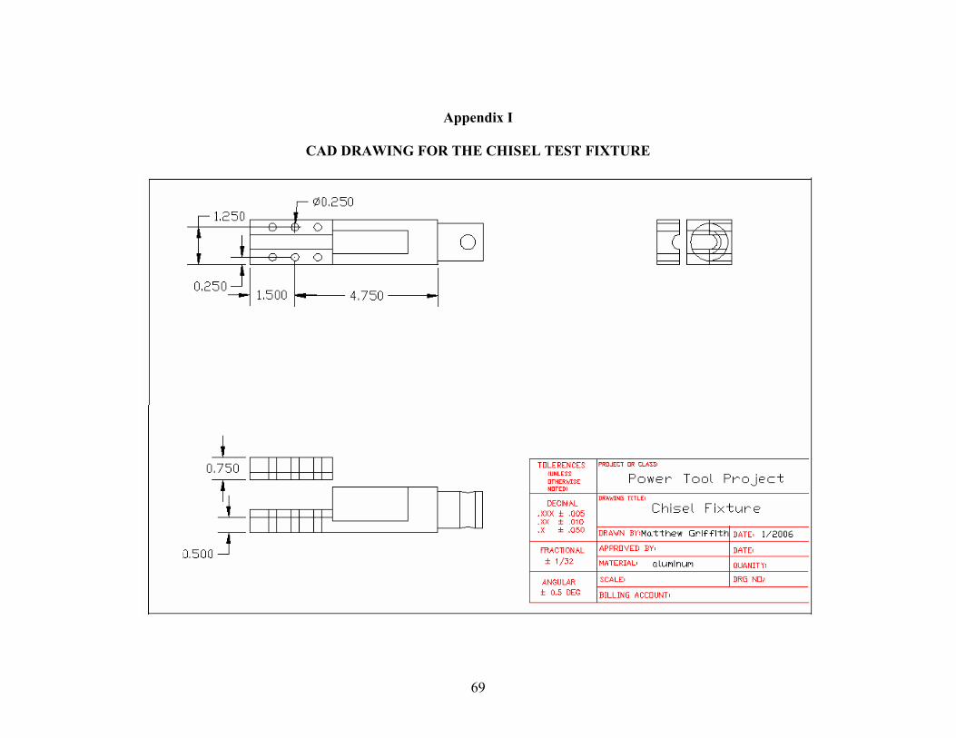
69
Appendix I
CAD DRAWING FOR THE CHISEL TEST FIXTURE

70