Embed Size (px)
Citation preview

ACRONYMSACAP advanced composites airframe programmeACT advanced composites technologyAFRL Air Force Research LaboratoryAST advanced subsonic transportATL automatic tape layerCAI compression after impactCFRP carbon fibre reinforced plasticCMC ceramic matrix compositeDASA Diamler-Chrysler AerospaceDC direct chillEFA European Fighter AircraftFRP fibre reinforced plasticGFRP} glass fibre reinforced plasticGRPHIP hot isostatic processingJSF Joint Strike FighterKFRP Kevlar fibre reinforced plasticLTM low temperature mouldingMIG metal inert gasMMC metal matrix compositeNCF non-crimped fabricOHC open hole compressivePEEK polyether ether ketonePMC polymer matrix compositePMMA polymethyl methacrylateRAM radar absorbent materialRCS radar cross sectionRFI resin film infusionRTM resin transfer mouldingTWI The Welding InstituteUD uni directionalUAV unmanned air vehicleVARTM vacuum assisted RTMVM vacuum mouldingVPPA variable polarity plasma arc
1.0 INTRODUCTIONThe prediction of the future is always a relatively uncertain process.The only certain fact is that the prediction is unlikely to be whollyaccurate. Even the prediction of trends following examination ofpast performance will be uncertain regarding the future rate of advance and may be entirely upset by new discoveries and theirapplication. This is as true for examining the future of airframe materials as it is for prediction of economic growth, which itselfsignificantly affects the development of materials technology in theaircraft industry. However, 100 years of powered manned flight doesgive a solid database from which to begin. In that period airframeshave moved from wood, wire and canvas, through to riveted andstressed skin metal structures to adhesively bonded polymercomposites. In each case the use of new materials is associated witha change in fabrication methods and it may be confidently antici-pated that this will remain true in the future. This fact accounts for ajustified conservatism in embracing new materials, not simplybecause of the need to develop experience and confidence in them,but also because of the costs associated with new constructionalmethods entailed in their application. It also, in part, accounts for thegenerally slower pace of application of new materials relative towhat is initially predicted: the other powerful brake being the state ofthe economy and the market for new aircraft at any particular time.The early prediction of the demise of aluminium and its replacementby polymer composites made in the 1980s(1) being a case in point,while the failure of alloys containing lithium to replace conventionalaluminium alloys had more to do with cost and decreasing fuelprices than any alloy development problems. It can, however, beexpected that, as in the twentieth century, military aircraft willexploit larger mass fractions of advanced materials and at earlierdates than civil transport aircraft, given their very different opera-tional requirements and much shorter design lives. The likely adventof unmanned combat aircraft may well accentuate this difference.
The drivers for materials developments for airframes in the twentyfirst century are principally reduction in weight and reduced acquisi-tion and direct operating costs while maintaining or enhancing safety.
THE AERONAUTICAL JOURNAL JUNE 2003 331
Materials for airframesH. M. FlowerDepartment of Materials Imperial College London UK
C. SoutisDepartment of AeronauticsAerospace EngineeringUniversity of SheffieldSheffield UK

Materials typically account for about 3·5% of the first cost of acivil airliner while production represents nearer 15%. Therefore,reduction in production costs (and reduction in weight) associatedwith reduced part numbers, especially mechanical fasteners, andincreased joint efficiency are goals which are to be sought and towhich materials developments must be directed. In looking to thefuture the further incremental development of 20th century materialswill be examined, together with the prospects for novel materials andprocesses likely to find volume application in airframes. For reasonsof space, those materials and processes which appear capable of onlyoccupying niche positions, however important, are excluded.
The mainstay of the metallic airframe throughout much of the lastcentury has been aluminium, supplemented by steel and by titaniumfrom the early 1950s and this is considered first.
2.0 ALUMINIUM ALLOYSThe discovery, reported by Wilm(2) only eight years after the firstpowered flight by the Wright brothers, of the phenomenon of agehardening led to the development of a number of alloys whosestrength, both proof and tensile, could be substantially increasedthrough heat treatment. The principle of establishing alloying elementsin solid solution by heat treatment at elevated temperature (typicallyaround 500°C), retention of the elements in supersaturated solution byrapid cooling to room temperature and decomposition of the solidsolution either by ‘natural’ ageing at room temperature or by ‘artifi-cial’ ageing at a higher temperature (in the range 100-200°C) has ledto a wide range of commercial alloys and heat treatment schedules.These are widely exploited in and beyond the aerospace sector: 2000series Al-Cu-Mg and 7000 series Al-Zn-Mg alloys being the systemsmost extensively employed in the latter while the 6000 series Al-Mg-Si system found its main applications elsewhere. However, the latteralloys offer reduced density compared to the copper containing mate-rials and if alloy development work aimed at achieving adequate agedstrength coupled with good corrosion resistance is successful, airframeapplications will increase at the expense of the 2000 series materials.
The alloying elements in solution produce relatively low levels ofstrengthening. However, if the heat treatment results in the decomposi-tion of the solid solution to form high density (typically 1024m–3) offine (nanometric scale) particles the interactions between these parti-cles and dislocations responsible for plastic deformation result insubstantial increases in the stress required to move the dislocations,and hence to an increased strength. As ageing continues the particlescoarsen and change their structure as functions of both time andtemperature and strength eventually peaks and then declines as furthercoarsening occurs. The underlying science of precipitation hardeningwas developed through the twentieth century and was of major assis-tance in the progressive development of alloy chemistry and of heattreatment schedules for aerospace applications. Although initially theemphasis was placed on increasing alloy strength, and this extended tothe 1950s, it was recognised that other factors also required considera-tion in alloy and heat treatment design. A most important factor istoughness and, in common with all engineering metals, there is aninverse relationship between strength and toughness of aluminiumalloys. Fracture mechanics, also a development of the twentiethcentury, demonstrated that as design stress is increased, to exploitincreases in alloy strength, the length of a crack which will cause fastfracture is rapidly reduced as it is proportional to the square of thetoughness divided by the stress and the former is decreased as alloystrength increases. Alloys which are not aged to peak strength there-fore exhibit greater damage tolerance than in the peak aged condition.It is also generally true that increasing aluminium alloy tensile strengthdoes not improve fatigue performance so that higher strength cannotbe effectively exploited in fatigue critical applications. Thus, forexample, in aircraft wings the lower skin, which experiences tensileforces, came to be manufactured from 2000 series medium strengthalloy in the naturally aged condition while the upper skin, which
experiences compressive stresses, is made from high strength 7000series alloy in a peak or near peak aged condition. Resistance to stresscorrosion cracking in the latter alloys also led to modifications to alloychemistry and to the use of multi-step ageing treatments. These aredesigned to produce precipitate distributions within the metal grainsfavourable to high strength, while avoiding grain boundary structureswhich are susceptible to stress corrosion cracking.
The materials science of phase transformations, precipitation andhardening mechanisms is now sufficiently mature that using thermo-dynamic and microstructural characterisation methods, together withsome basic experimental determination of precipitation reactions, it isnow possible to model the processes and the strengthening via solutionand precipitation hardening in aluminium alloys and to predict thebehaviour of novel compositions(3). This will be of increasing value inthe present century in alloy development as new criteria for alloyselection arise: for example alloys capable of higher temperature oper-ation (should the market look favourably upon the development of asecond generation supersonic airliner). New manufacturing methodswill impose additional and different demands on alloy properties fromthose required to date. For example the creep forming of curved wingstructures (including curvature about two axes) is being developed,and exploits the elevated temperature, slow strain rate creep deforma-tion of the material to plastically deform it under relatively low load tothe required shape. The alloy, ideally, should exhibit a low creep resis-tance and be amenable to ageing during the creep forming such that,post-forming, the required room temperature strength can be obtained.Current 2000 and 7000 series alloys are not optimised for suchprocessing and revised alloy compositions must be considered: model-ling can reduce substantially the matrix of experimental variants to beexplored.
In the twentieth century integral machining has become highlysophisticated with very high rates of metal removal possible undercomputer control to produce sections of considerable length (of theorder of 20m)(4). The move towards larger structures and fewer partshas led to demands for thicker and longer plate from which morecomplex sections can be machined. This provides particular problemsfor metal suppliers. In order to achieve relatively uniform throughthickness properties, and to close up central microporosity (essentialfor fatigue resistance), substantial reductions in thickness by rollingare required. This implies that to make thick plate, thicker cast billet ofuniform structure and composition must be manufactured. Anisotropyof alloy microstructure also results in lower mechanical properties inthe short transverse direction of loading in structure made from plateand minimisation of this anisotropy must be sought. Thus each stepfrom DC casting through to plate rolling must be optimised to meet anapplication requirement which is unique to the aerospace sector: amarket which consumes annually only about 10% as much aluminiumas that which goes to make beverage cans alone(5)! It is also selfevident that, in spite of a long record of success, the machining ofalloy plate into wing skin with integral stiffening stringers with theconsequent reduction of much of the metal to swarf (over 90% insome cases) is not intrinsically the best way to use the metal. Alterna-tives require the joining of parts, eg separate stringers to skin, whileachieving a joint strength to match that of the integrally machinedsection. Welding is the most likely solution but must produce the leastdisruption to the metallurgical structure of the materials being joinedand must produce welds of highly consistent and adequate quality.The development of friction stir welding by TWI in this country(6)
shows considerable promise but may be limited in application byconsiderations of joint geometry. Fusion welding processing,including laser, hybrid laser/MIG welding and variable polarityplasma arc (VPPA) welding are all being evaluated for aerospaceapplication. Welding also offers the prospect of joining dissimilaralloys, including upper (7000 series) and lower (2000 series) spar partsto produce more efficient structures. Applications naturally extend tofuselage components where requirements and constraints differ fromthose relating to wing structure. Experimental evaluation of allpossible welding processes, current alloys (let alone developmental
332 THE AERONAUTICAL JOURNAL JUNE 2003

materials designed for improved weldability) and fillers, would be amassive task and modelling of the materials and of the welding mustbe exploited to reduce the volume of experimental work required.
The replacement of riveting as a joining method can lead, in prin-ciple, to substantial weight, part number and cost savings although theremoval of the crack stoppers represented by riveted joints must bethoroughly considered in design. Welding will also play its part inachieving this end. Other competing methods have been developedand employed in the last century, adhesive bonding, for example,having a record of development dating back to the second world war.In the latter part of the century the science of adhesive bonding and therole of surface preparation and treatment advanced considerably(7) andthe method has become a tool of the aircraft construction industry. It iscertain that further advances in adhesives and bonding technology willfurther advance this in the current century. While design of the jointgeometry can ensure that the load bearing capacity of an adhesivejoint is equal to that of the surrounding metal structure it appears veryunlikely that the stresses which the joint can bear will be increased toapproach that of the parent metal so there will always be a degree ofmechanical inefficiency in such bonds. An alternative which, in prin-ciple, can achieve this goal is diffusion bonding. This requires the twometal surfaces to be brought into such intimate contact, at elevatedtemperature, that atomic diffusion can occur across the interface andcan eventually result in the complete elimination of that interface. Thisideal can effectively be obtained using titanium alloys which, aboveabout 600°C conveniently dissolve the very thin surface oxide filmwhich protects them at low temperatures thus allowing metal to metalcontact across the bond line. Aluminium alloys are not so obliging anda key step in diffusion bonding is the break up of the tenacious surfaceoxide film. This can be aided mechanically or via introduction of areactive interlayer which subsequently dissolves into the metal oneither side of the joint line. Although a number of such processes havebeen developed in the laboratory and provide joints of good strength,transition to the production line requires the ability to produce joints ofhigh and consistent quality and this goal remains elusive. However,there appear to be no intrinsically insurmountable scientific or tech-nical problems and further development may well lead to successfulapplication in the future. Diffusion bonding is employed in associationwith superplastic forming in the case of titanium component manufac-ture and would also be appropriate to aluminium alloys. A number ofthese can be processed to exhibit superplasticity. The phenomenonallows the use of tensile forming loads at elevated temperature: some-thing which normally is avoided due to the loss of work hardeningcapability in the alloy. For the manufacture of sheet metal into threedimensional forms tensile forces cannot be avoided, and cold working
at low homologous temperatures, involving high working loads andshape distortion by elastic springback when the forming load isremoved, have to be dealt with. A material which is stable in tensiledeformation at elevated temperature enjoys the twin advantages of lowforming loads and low springback. In engineering alloys, specialprocessing is required to produce internal microstructures which resultin superplastic behaviour, allowing tensile strains of several hundredpercent to be achieved. The first such alloy ‘supral’ AA2004 wasdeveloped in this country, commercialised in the 1970s, and used, forexample, to form the engine intakes for the BAe Hawk aircraft (Fig. 1(a)). Since then superplastic 5000 and 7000 series alloys havebeen developed and exploited and the phenomenon has been observedin alloys containing lithium (e.g. AA8090). In their superplastic formthe special processing required, results in much higher costs than thoseof their non-superplastic equivalents(8). Current materials require rela-tively slow forming rates (strain rate ~ 10–3s–1): this is less of aproblem in the aircraft industry than in the mass automotive sector,since production rates are much lower, but the cost of long processtimes is not insignificant. There are a number of routes to producematerial with increased superplastic strain-rate-forming-capabilitywhich have been successfully developed in the laboratory. Theseinclude equal channel angular extrusion, which can produce an appro-priate internal microstructure, and the use of exotic alloying additionssuch as scandium. The former appears unlikely to be able to delivermaterial in sufficient size to be attractive for airframe manufacture,while the latter is currently extremely expensive (currently ~$7/g(9))due to only very limited sources being commercially available.However, should this situation change through the discovery andexploitation of new ore sources, scandium could become a veryimportant minor alloying addition, since it beneficially modifies notonly superplastic alloy microstructure but also other important charac-teristics such as weldability. Other routes, such as particulate castingcombined with roll consolidation, offer the prospect of commerciallyviable 5000 series Al-Mg-Zr and 6000 series Al-Mg-Si-Zr productswhich, in the laboratory, also exhibit superplasticity at high strainrates(8, 10). If the process can be coupled to diffusion bonding, orperhaps laser welding, it would offer the ability to manufacture highlyefficient internally stiffened hollow panel structures.
Casting is one of the oldest metallurgical processes for producingproducts of complex shape and is one that can substantially reduce thenumber of detail parts. However, in the last century it was not fullyexploited in the aerospace sector because (a) mechanical properties ofcastings (including strength, ductility and damage tolerance) havebeen substantially lower than those of wrought alloy forms (b) thevariability of properties has been much greater than for wrought
FLOWER AND SOUTIS MATERIALS FOR AIRFRAMES 333
Figure 1a. Above: Superformed one piece air Intake from the BAeHawk. Courtesy of Superform Aluminium.
Figure 1b. Single piece Superformed door stiffener from the Learjet 45.Courtesy of Superform Aluminium.
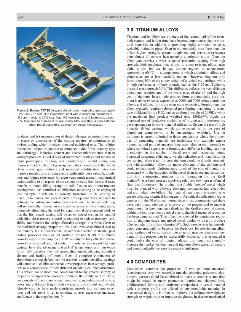
products and (c) incorporation of design changes requiring alterationin shape or dimensions of the casting requires re-optimisation ofrevised tooling which involves time and additional cost. The inferiormechanical properties are due to entrapped oxide films, porosity (gasand shrinkage), inclusion content and coarser microstructure than inwrought products. Good design of investment castings and the use ofrapid prototyping, filtering and non-turbulent mould filling canminimise oxide content. Degassing can reduce porosity and the use ofclean alloys, grain refiners and increased solidification rates canimprove metallurgical structure and significantly raise strength, tough-ness and fatigue resistance. In recent years much greater metallurgicalunderstanding of all aspects of the casting process, from heat and masstransfer in mould filling through to solidification and microstructuredevelopment, has permitted solidification modelling to be employed(for example in relation to porosity formation in DC casting ofbillet(11)) to reduce the experimental development work required tooptimise the casting and casting process design. The use of modellingwill undoubtedly increase in scale and accuracy in the coming years,ultimately eliminating the need for experimental development work sothat the first actual casting will be an optimised casting. In parallelwith this, close process control is required to reduce property vari-ability and increase the design allowable strength to a value closer tothe statistical average properties: this does involve additional cost tothe foundry but is essential in the aerospace sector. Remedial postcasting processes such as hot isostatic pressing (HIP) to eliminateporosity may also be employed. HIP can only be fully effective whereporosity is enclosed and not coated in oxide (in this regard titaniumcastings have the advantage that at HIP temperatures any thin oxidefilms fully dissolve into the surrounding metal, allowing completeclosure and healing of pores). Even if complete elimination ofaluminium casting defects can be assured, aluminium alloy castingswill continue to exhibit somewhat lower properties than wrought prod-ucts as a consequence of their different metallurgical microstructures.This deficit can be more than compensated for by greater isotropy ofproperties compared to wrought products, the ability to form largecomponents of three dimensional complexity, including panel covers,doors and bulkheads (Fig.2) with savings in overall cost and weight.Already castings have made significant inroads into airframe struc-tures and this trend is set to continue as user experience increasesconfidence in their application(12).
3.0 TITANIUM ALLOYSTitanium and its alloys are products of the second half of the twen-tieth century and in that time have become important airframe struc-tural materials, in addition to providing highly corrosion-resistant,weldable hydraulic pipes. Even in commercially pure form titaniumoffers higher strength, greater toughness and corrosion-resistancethan almost all current heat-treatable aluminium alloys. Titaniumalloys can provide a wide range of properties ranging from highstrength, high toughness beta alloys, to creep resistant alloys, nearalpha alloys, for use in gas turbine engines at temperaturesapproaching 600°C — a temperature at which aluminium alloys andcomposites are at least partially molten. However, titanium onlyforms about 10% of the empty weight of a typical civil airliner, whilein high performance military aircraft, such as the F-22 and Typhoon,the total can approach 50%. This difference reflects the very differentoperational requirements of the two classes of aircraft and the highcost of titanium. In a simple product form, commercially pure tita-nium is about twice as expensive as 2000 and 7000 series aluminiumalloys, and alloyed forms are even more expensive. Forging titaniumalloys typically requires substantial post forging machining (a proto-type bulkhead for the F-22 had an as-forged-weight of 2950Kg whilethe machined final product weighed only 150Kg(13)). Again theincreased use of predictive modelling of forging and microstructuredevelopment can improve material utilisation. So can the use of highintegrity HIPed castings which are expected, as in the case ofaluminium components, to be increasingly exploited. Use inairframes is currently limited to those applications where the proper-ties of competing materials are inadequate (for example enginemountings and parts of undercarriage assemblies in civil aircraft) orwhere combined superplastic forming and diffusion bonding result ina reduction in the number of detail parts and mechanical joints,increased structural efficiency, weight reduction and manufacturingcost saving. Were it not for cost, titanium would be directly competi-tive with aluminium alloys for major elements of the airframe andcould replace steels. Unfortunately much of the cost of titanium isassociated with the extraction of the metal from its ore and consolida-tion into engineering product forms. Extraction by the Krollmethod(14) is a batch process involving relatively low masses of metal(less than 10tonnes). The product is a friable ‘sponge’ metal whichmust be blended with alloying elements, compacted into electrodesand arc melted into billets. The material may need triple melting toensure adequate chemical homogeneity for critical applications (eg inengines). In the 50 plus year period since it was commercialised therehave been many attempts to improve on the process and to make itcontinuous. To date none have displaced the Kroll process. However,within the last three years a novel electrochemical means of reductionhas been demonstrated. This offers the potential for continuous reduc-tion of titanium oxide and mixed metal oxides to directly producealloy powder of uniform chemistry(15). Such powder can be consoli-dated conventionally or become the feedstock for powder metallur-gical methods of consolidation into sheet or near net shape compo-nents. If this process can be successfully scaled up it is estimated itcould halve the cost of titanium alloys: this would substantiallyincrease the market for titanium and titanium alloys across all sectorsand would radically increase the usage in airframes.
4.0 COMPOSITESComposites combine the properties of two or more materials(constituents). Any two materials (metals, ceramics, polymers, elas-tomers, glasses) could be combined to make a composite and theymight be mixed in many geometries (particulate, chopped-fibre,unidirectional fibrous and laminated composites) to create materialwith a property-profile not offered by any monolithic material. Inmechanical design, it is often to improve the stiffness-to-weight orstrength-to-weight ratio or improve toughness. In thermo-mechanical
334 THE AERONAUTICAL JOURNAL JUNE 2003
Figure 2. Boeing 737NG forward airstair door measuring approximately25 × 58 × 117cm. It is investment cast with a minimum thickness of
0.2cm. It weighs 20% less, has 143 fewer parts and fasteners, takes75% less time to manufacture and costs 44% less than a conventional
sheet metal assembly. Courtesy of Aeromet International.

design, it is to reduce thermal expansion, or to maximise heattransfer, or to minimise thermal distortion. These are some examples,but the method is more general, it covers most mechanical andthermal properties.
Within the last forty years there has been a rapid increase in theproduction of synthetic composites, those incorporating fine fibres invarious plastics (polymers) dominating the market. Predictionssuggest that the demand for fibre reinforced plastics (FRP) willcontinue to increase steadily with metal ((MMC) and ceramic (CMC)based composites making a more significant contribution.
Fibrous composites have found applications in aircraft from thefirst flight of the Wright Brothers’ Flyer 1, in North Carolina on 17December 1903, to the plethora of uses now enjoyed by them on bothmilitary and civil aircraft. In addition there are more exotic applica-tions on UAVs, space launcher vehicles and satellites. Their growinguse has arisen from their high specific strength and stiffness, whencompared to the more conventional materials, and the ability to shapeand tailor their structure to produce more aerodynamically efficientstructural configurations.
Fibre reinforced polymers, especially carbon fibre reinforced plas-tics (CFRP) can, and will in the future, contribute more than 50% ofthe structural mass of an aircraft(16, 17). However, affordability is thekey to survival in aerospace manufacturing, whether civil or military,and therefore effort should be devoted to analysis and computationalsimulation of the manufacturing and assembly process, as well as thesimulation of the performance of the structure, since they are inti-mately connected.
4.1 Metal matrix composites
Metal matrix composites, based on aluminium, have been researchedin a wide variety of forms in recent years. The combination of proper-ties obtained, differs substantially, depending on the form and distrib-ution of the ceramic. For example, monofilament fibre reinforcedaluminium (such as those employed in the space shuttle(18), providevery high strength, stiffness and fatigue resistance parallel to thefibres’ axis, but low toughness and generally greatly inferior proper-ties in the transverse direction. Aluminium containing ceramic partic-ulate (typically silicon carbide) exhibits more isotropic propertieswith greater toughness. Each type will lend itself to a particular nicheapplication (eg high stiffness struts) but none are likely to findvolume applications in airframe construction. The exception to this isa class of hybrid composites which contain fibre reinforced polymersandwiched between aluminium alloy sheets. Commercially devel-oped materials are Arral (containing aramid fibres) and Glare (withglass fibres)(19). The latter has been selected for upper fuselage skin inthe new A380 Airbus (Fig. 3). Among its many advantages are theability to form very large panels, use of conventional assembly
methods, reduced crack growth rates, increased fire and throughthickness corrosion resistance compared to aluminium, while havingsuperior lightning strike resistance, toughness and damage tolerancecompared to polymer composites. It has been estimated that its usecan save 25% in weight compared to conventional panel structures,albeit at a material cost several times as great. There is clearly consid-erable room for further development of such hybrid composites, bothin terms of choice of alloy (including titanium) and of polymer/fibrecombinations and this may be expected in the coming years.
4.2 Fibre reinforced plastics
4.2.1 Fibre types
Glass fibre reinforced composites (GRP) have been used on militaryaircraft dating from 1940, but their poor relative specific stiffness hasprevented them from extending the foothold they have found in fair-ings, doors, etc. to the primary structural applications of wings,stabilisers and major fuselage sections. The most commonly usedglasses are based on silica (Si02) with additions of oxides of calcium,boron, sodium, iron and aluminium. These glasses are usually amor-phous although crystallisation may occur after prolonged heating athigh temperatures. The strength and modulus of glass is determinedprimarily by the three-dimensional structure of the constituent oxides.E-glass (E for electrical) is the most commonly used glass because itdraws well and has good strength (~3·5GPa), stiffness (~75GPa),electrical and weathering properties. C-glass (C for corrosion) has ahigher resistance to chemical corrosion than E-glass but is moreexpensive and has lower strength properties. S-glass is more expen-sive than E-glass but has a higher Young’s modulus and is moretemperature resistant. It is used in the aircraft industry where thehigher modulus can justify the cost. To give an illustration of thegrowth in the use of glass fibre components in successive Boeingplanes: a total area of 19m2 was typical for a 707 aircraft; 167m2 forthe 727; 279m2 for the 737 and 929m2 for the 747 types.
Aramid fibres introduced in the 1960s found parallel applicationswith glass fibres, but their lack of specific stiffness and poorcompressive strength limited their use, despite the damage tolerancethat composites utilising these fibres can afford. The most successfulcommercial aramid fibre to date has been developed by the Du Pontcompany with the trade name Kevlar. It was hoped at one time toreplace carbon on primary structures and glass on secondary ones.There is little detail available about the manufacturing process but theinitial patent in 1968 claims that poly-para-benzamide fibres can beproduced with a modulus of 130GPa by a solvent spinningprocess(20). Two forms, Kevlar 29 and Kevlar 49, are available.Kevlar 29 was developed for tyre cord reinforcement and has a highstrength and intermediate modulus, while Kevlar 49 has a highermodulus and is the preferred fibre for high performance composites(KFRP).
The adoption of composite materials as a major contribution toaircraft structures followed on from the discovery of carbon fibre atthe Royal Aircraft Establishment at Farnborough, UK, in 1964.However, not until the late 1960s did these new composites start to beapplied, on a demonstration basis, to military aircraft. Examples ofsuch demonstrators were trim tabs, spoilers, rudders and doors. Withincreasing application and experience of their use, came improvedfibres and matrix materials (thermosets and thermoplastics), resultingin CFRP composites with improved mechanical properties, allowingthem to displace the more conventional materials, aluminium and tita-nium alloys, for primary structures. High strength, high moduluscarbon fibres are about 5 to 6µm in diameter and consist of smallcrystallites of ‘turbostratic’ graphite, one of the allotropic forms ofcarbon. The graphite structure consists of hexagonal layers, in whichthe bonding is covalent and strong (~525kJ/mol) and there are weakvan der Waal forces (< 10kJ/mol) between the layers(20, 21). Thismeans that the basic crystal units are highly anisotropic; the in-plane
FLOWER AND SOUTIS MATERIALS FOR AIRFRAMES 335
Figure 3. Materials usage in the Airbus A380 showing upper fuselagepanels in Glare. From: Structures and Materials Laboratory, University of Delft
website.
Young’s modulus parallel to the a-axis is approximately 1000GPaand the Young’s modulus parallel to the c-axis normal to the basalplanes is only 30GPa. Alignment of the basal plane parallel to thefibre axis gives stiff fibres, which, because of the relative low densityof around 2Mg/m3, have extremely high values of specific stiffness(~200GPa/(Mg/m3)). Imperfections in alignment, introduced duringthe manufacturing process result in complex-shaped voids elongatedparallel to the fibre axis. These act as stress raisers and points ofweakness leading to a reduction in strength properties. Other sourcesof weakness, which are often associated with the manufacturingmethod, include surface pits and macro-crystallites. The arrangementof the layer planes in the cross-section of the fibre is also importantsince it affects the transverse and shear properties of the fibre. Thus,for example, the normal polyacrylonitrile-based (PAN-based) Type Icarbon fibres have a thin skin of circumferential layer planes and acore with random crystallites. In contrast, some mesophase pith-basedfibres exhibit radially oriented layer structures. These different struc-tures result in some significant differences in the properties of thefibres and of course those of the composites.
Refinements in fibre process technology over the past twenty yearshave led to considerable improvements in PAN-based fibres. Thesecan now be supplied in three basic forms, high modulus (HM,~380GPa), intermediate modulus (IM, ~290GPa) and high strength(with a modulus of around 230GPa and tensile strength of 4·5GPa).The more recent developments of the high strength fibres have led towhat are known as high strain fibres, which have strain values of 2%before fracture. The tensile stress-strain response is elastic up tofailure and a large amount of energy is released when the fibres breakin a brittle manner.
The application of carbon fibre has developed from small-scaletechnology demonstrators in the 1970s to large structures today. Frombeing a very expensive exotic material when first developed rela-tively few years ago, the price of carbon fibre has dropped to about£10/kg, which has increased applications such that the aerospacemarket accounts for only 20% of all production. The selection of theappropriate fibre depends very much on the application. For militaryaircraft both high modulus and high strength are desirable. Satelliteapplications, in contrast, benefit from use of high fibre modulus,improving stability and stiffness for reflector dishes, antennas andtheir supporting structures.
Rovings are the basic forms in which fibres are supplied, a rovingbeing a number of strands or bundles of filaments wound into apackage or creel, the length of the roving being up to several kilome-tres, depending on the package size. The term roving is usually appliedto glass fibres, whereas bundles of continuous carbon or aramid fibresare often referred to as tows, this name reflecting the textile fibre tech-nology involved in their manufacture. A strand of glass fibres containstypically some 200 filaments; each approximately 10µm in diameter,and the number of strands in the roving will depend upon the type ofapplication for which the glass fibre is employed. Carbon fibres areproduced in a variety of tow sizes ranging from a few hundred fila-ments per tow to 32,000 per tow with the commonest sizes of 3,000,6,000 and 12,000 ends. Rovings or tows can be woven into fabrics,and a range of fabric constructions are available commercially, such asplain weave, twills and various satin weave styles, woven with achoice of roving or tow size depending on the weight or density offabric required. Fabrics can be woven with different kinds of fibre, forexample carbon in the weft and glass in the warp direction, and thisincreases the range of properties available to the designer. One advan-tage of fabrics for reinforcing purposes is their ability to drape orconform to curved surfaces without wrinkling. It is now possible, withcertain types of knitting machine, to produce fibre performs tailored tothe shape of the eventual component. Generally speaking, however,the more highly convoluted each filament becomes, as at crossoverpoints in woven fabrics, or as loops in knitted fabrics, the lower itsreinforcing ability(18).
The fibres are surface treated during manufacture to prepare adhesion with the polymer matrix, whether thermosetting (epoxy,
polyester, phenolic, polyimide resins) or thermoplastic (polypropy-lene, Nylon 6.6, PMMA, PEEK). The fibre surface is roughened bychemical etching and then coated with an appropriate size to aidbonding to the specified matrix. Whereas composite strength isprimarily a function of fibre properties, the ability of the matrix toboth support the fibres and provide out-of-plane strength is, in manysituations, equally important. The aim of the material supplier is toprovide a system with a balanced set of properties. While improve-ments in fibre and matrix properties can lead to improved lamina orlaminate properties, the all-important field of fibre-matrix interfacemust not be neglected.
The load acting on the matrix has to be transferred to the rein-forcement via the interface. Thus fibres must be strongly bonded tothe matrix if their high strength and stiffness are to be imparted tothe composite. The fracture behaviour is also dependent on thestrength of the interface. A weak interface results in a low stiffnessand strength but high resistance to fracture, whereas a strong inter-face produces high stiffness and strength but often a low resistanceto fracture, i.e., brittle behaviour. Conflict therefore exists and thedesigner must select the material most nearly meeting his require-ments. Other properties of a composite, such as resistance to creep,fatigue and environmental degradation, are also affected by the char-acteristics of the interface. In these cases the relationship betweenproperties and interface characteristics are generally complex andanalytical/numerical models supported by extensive experimentalevidence are required.
4.2.2 Matrix materials
Thermoplastic materials are becoming more available, however, themore conventional matrix materials currently used are thermosettingepoxies. The matrix material is the Achilles’ heel of the compositesystem and limits the fibre from exhibiting its full potential in termsof laminate properties. The matrix performs a number of functionsamongst which are stabilising the fibre in compression (providinglateral support), translating the fibre properties into the laminate,minimising damage due to impact by exhibiting plastic deformationand providing out-of-plane properties to the laminate. Matrix domi-nated properties (interlaminar strength, compressive strength) arereduced when the glass transition temperature is exceeded andwhereas with a dry laminate this is close to the cure temperature, theinevitable moisture absorption reduces this temperature and hencelimits the application of most high-temperature-cure thermosetepoxy composites to less than 120°C.
Conventional epoxy aerospace resins are designed to cure at 120-135°C or 180°C usually in an autoclave or close cavity tool† at pres-sures up to 8bar, occasionally with a post cure at higher temperature.Systems intended for high temperature applications may undergocuring at temperatures up to 350°C. The resins must have a roomtemperature life beyond the time it takes to lay-up a part and havetime/temperature/viscosity suitable for handling. The resultant resincharacteristics are normally a compromise between certain desirablecharacteristics. For example improved damage tolerance perfor-mance usually causes a reduction in hot-wet compression properties,and if this is attained by an increased thermoplastic content then theresin viscosity can increase significantly. Increased viscosity is espe-cially not desired for a resin transfer moulding (RTM) resin where aviscosity of 50cPs or less is often required, but toughness may alsobe imparted by the fabric structure such as a stitched non-crimpedfabric (NCF).
The first generation of composites introduced to aircraft construc-tion in the 1960s and 1970s employed brittle epoxy resin systemsleading to laminated structures with a poor tolerance to low-energyimpact caused, for example, by runway debris thrown up by aircraftwheels or the impacts occurring during manufacture and subsequentservicing operation. Although the newer toughened epoxy systems
336 THE AERONAUTICAL JOURNAL JUNE 2003
† A close cavity tool is a two part mould.
provide improvements in this respect, they are still not as damagetolerant as thermoplastic materials. A measure of damage toleranceis the laminate compression after impact (CAI) and the laminateopen hole compressive (OHC) strengths. The ideal solution is toprovide a composite exhibiting equal OHC and CAI strengths andwhile the thermoplastics are tougher, they have not capitalised onthis by yielding higher notched compression properties than the ther-moset epoxy composites. Polyetheretherketone (PEEK) is a rela-tively costly thermoplastic with good mechanical properties. Carbonfibre reinforced PEEK is a competitor with carbon fibre/epoxies andAl-Cu and Al-Li alloys in the aircraft industry. On impact at rela-tively low energies (5-10J) carbon fibre-PEEK laminates show onlyan indentation on the impact site while in carbon fibre-epoxysystems ultrasonic C-scans show that delamination extends a consid-erable distance affecting more dramatically the residual strength andstiffness properties of the composite. Another important advantageof carbon fibre-PEEK composites is that they possess unlimitedshelf-life at ambient temperature; the fabricator does not have to beconcerned with proportioning and mixing resins, hardeners andaccelerators as with thermosets, and the reversible thermal behaviourof thermoplastics means that components can be fabricated morequickly because the lengthy cure schedules for thermosets, some-times extending over several hours, are eliminated.
It can be seen that in the effort to improve the through-the-thick-ness strength properties and impact resistance, the compositesindustry has moved away from brittle resins. It has progressed tothermoplastic resins, toughened epoxies, through damage tolerantmethodology, Z-fibre (carbon, steel or titanium pins driven throughthe z-direction to improve the through thickness properties), stitchedfabrics, stitched performs and the focus is now on affordability. Thecurrent phase is being directed towards affordable processingmethods such as non-autoclave processing, non-thermal electronbeam curing by radiation and cost effective fabrication. NASALangley in the USA claims a 100% improvement in damage toler-ance performance with stitched fabrics relative to conventional mate-rials (ref. Advanced Composites Technology, (ACT), programmewhere non-crimped fabric (NCF) laminates are processed by resinfilm infusion, (RFI)). It is essential that if composites were tobecome affordable they must change their basic processes to getaway from pre-preg material technology, which currently results inan expensive solution and hence product(17). However, autoclavedcontinuous fibre composites will still dominate for the high levels ofstructural efficiency required.
4.2.3 Design and analysis
It is accepted that designs in composites should not merely replacethe metallic alloy but should take advantage of exceptionalcomposite properties if the most efficient designs are to evolve. Ofcourse the design should account for through-thickness effects thatare not encountered in the analysis of isotropic materials. Forinstance, in a laminated structure since the layers (laminae) are elas-tically connected through their faces, shear stresses are developed onthe faces of each lamina. The transverse stresses (σz, τxz, τyz) thusproduced, can be quite large near a free boundary (free edge, cut-out,an open hole) and may influence the failure of the laminate. A largeinterlaminar shear stress at the interface may produce matrix cracksat the free edge(22). These cracks then propagate into the laminateand initiate delaminations, leading to stiffness loss and prematurefailure. This initial damage at the laminate edge or hole edge is quiteimportant for fatigue loading in which the ultimate failure mayinitiate at the edges.
The laminate stacking sequence can significantly influence themagnitude of the interlaminar normal and shear stresses, and thus thestacking sequence of plies can be important to a designer. It has beenreported that the fatigue strength of a (±15/±45)s Boron fibre/epoxylaminate is about 175MPa lower than a (±45/±15)s laminate of thesame system. The interlaminar normal stress, σzz, changes from
tension to compression by changing the stacking sequence and thusaccounts for the difference in strengths. In this case progressivedelamination is the failure mode in fatigue. Approximate analyticalmethods and numerical approaches such as finite difference andfinite element (FE) techniques can be used to analyse the interlam-inar stress distributions near free edges, open holes, bolted joints (acomplex three-dimensional problem) and help to identify theoptimum fibre orientation and laminate stacking sequence for thegiven loading and kinematic boundary conditions.
The lay-up geometry of a composite strongly affects not onlycrack initiation but also crack propagation, with the result that somelaminates appear highly notch sensitive whereas others are totallyinsensitive to the presence of stress concentrators. The selection offibres and resins, the manner in which they are combined in the lay-up, and the quality of the manufactured composite, must all be care-fully controlled if optimum toughness is to be achieved. Furthermore,materials requirements for highest tensile and shear strengths oflaminates are often incompatible with requirements for highesttoughness. Compared with fracture in metals, research into the frac-ture behaviour of composites is in its infancy. Much of the necessarytheoretical framework is not yet fully developed and there is nosimple recipe for predicting the toughness of all composites. It is notyet possible to design with certainty the structure of any compositeso as to produce the optimum combination of strength and toughness.
In metallic and plastic materials, even relatively brittle ones,energy is dissipated in non-elastic deformation mechanisms in theregion of the crack tip. This energy is lost in moving dislocations in ametal and in viscoelastic flow or craze formation in a polymer. Incomposites, the fibres interfere with crack growth, but their effectdepends on how strongly they are bonded to the matrix (resin). Forexample, if the fibre/matrix bond is strong, the crack may runthrough both fibres and matrix without deviation, in which case thecomposite toughness would be low and approximately equal to thesum of the separate component toughnesses. On the other hand, if thebond is weak the crack path becomes very complex and many sepa-rate damage mechanisms may then contribute to the overall fracturework of the composite. For example, a brittle polymer or epoxy resinwith a fracture energy G =~ 0·1kJm–2 and brittle glass fibres with G =~0·01kJm–2 can be combined together in composites some of whichhave energies of up to 100kJm–2. For an explanation of such a largeeffect it is necessary to look beyond simple addition(22).
Fracture in composite materials seldom occurs catastrophicallywithout warning, but tends to be progressive, with substantialdamage widely dispersed through the material. Tensile loading canproduce matrix cracking, fibre bridging, fibre pull-out, fibre/matrixdebonding and fibre rupture, which provide extra toughness anddelay failure. The fracture behaviour of the composite can be reason-ably well explained in terms of some summation of the contributionsfrom these mechanisms but as said earlier it is not yet possible todesign a laminated composite to have a given toughness.
Another important modelling issue is the fatigue life of thecomposite. In contrast to homogeneous materials, in which fatiguefailure generally occurs by the initiation and propagation of a singlecrack, the fatigue process in composite materials is very complexand involves several damage modes, including fibre/matrix de-bonding, matrix cracking, delamination and fibre fracture (tensile orcompressive failure in the form of fibre microbuckling or kinking).By a combination of these processes, widespread damage developsthroughout the bulk of the composite and leads to a permanentdegradation in mechanical properties, notably laminate stiffness andresidual strength.
The general sequence of damage events in a multi-ply laminateunder fatigue loading is the same as under static loading. At highfatigue stresses, cracks can initiate on the first loading cycle and thenaccumulate with increasing number of cycles. However, cracks candevelop even when the maximum cyclic stress is well below thestatic cracking threshold although only after an ‘incubation period’of hundreds of thousands of cycles (depending on peak stress).
FLOWER AND SOUTIS MATERIALS FOR AIRFRAMES 337

Cracks generally initiate at the free edge but can also initiate awayfrom the edge (for example, in GFRP 0/90/0 laminates with thin 90°plies). Although crack patterns viewed on the coupon edge mayappear similar under static and cyclic loading, the extent of cracksacross the width of the ply may be significantly different in fatigue.The fatigue crack pattern can differ from the evenly spaced array offull-width cracks generally observed at static saturation. Observa-tions of transverse ply crack development in 0/90/0 laminates showthat the pattern of cracks depends on the load level. Transverse plycracks are observed to grow stably across the width of the ply underfatigue loading (compared with instantaneous crack propagationacross the ply width under static loading) at a rate which depends onthe cyclic stress level and on interaction with neighbouring cracks.Crack arrest can occur at sufficiently small crack spacings. The earlyinitiation of matrix cracking in fatigue, relative to static loading,consequently leads to a decrease in the threshold for the onset ofother types of damage. Delaminations can propagate over manythousands of cycles, resulting in separation of the laminate intodiscrete laminae (which continue to support tensile load via the 0°plies). The presence of off-axis ply cracks (±θ plies) may beexpected to accelerate damage in the laminae by promoting fibrefailures in the adjacent load-bearing 0° plies. Analysis of the stressesat the intersection of matrix cracks in adjacent plies of differentorientation shows that there is a highly localised region of increasedinterlaminar normal and shear stress around the point of intersection,which could be an initiation point for failure of the laminate. Fibrefailure may result from these locally enhanced stresses. Themaximum cyclic stress (or strain) can be plotted as a function offatigue cycles to show regions of dominance of individual damagemechanisms in the fibre, matrix and interface, from which the contri-bution of each to the overall fatigue response can be evaluated.However, this process involves extensive experimental testing that istime consuming and expensive, suggesting that the field woulddramatically benefit from the development of analytical/numericaltools that can successfully simulate damage accumulation, and ulti-mately predict fatigue life.
Although these complexities (free edge effects, impact damage,joints, fatigue life prediction) lengthen the design process, they aremore than compensated for by the mass savings and improvementsin aerodynamic efficiency that result. The finite element analysis isalso a crucial component and the biggest time saving strides havebeen in the user-friendly developments in creating the data and inter-preting the results using modern sophisticated graphical user inter-faces. The key is using parametric software to generate the geometryand the meshes. Apparently it used to take Boeing (Phantom Works)in St Louis, USA, more than six months to perform the initial FEelement stiffness and strength analysis for a complete aircraft andthis now takes less than three weeks with a handful of engineers, socomposites can become more attractive(17).
The majority of aircraft lift and control surfaces have a singledegree of curvature due to limitations of metal fabrication tech-niques. Improvements in aerodynamic efficiency can be obtained bymoving to double curvature allowing, for example, the production ofvariable camber, twisted wings. Composites and modern mould toolsallow the shape to be tailored to meet the required performancetargets at various points in the flying envelope. A further benefit isthe ability to tailor the aeroelasticity of the surface to furtherimprove the aerodynamic performance. This tailoring can involveadopting laminate configurations that allow the cross-coupling offlexure and torsion such that wing twist can result from bending andvice-versa. Finite element analysis allows this process of aeroelastictailoring, along with strength and dynamic stiffness (flutter) require-ments, to be performed automatically with a minimum of post-analysis engineering yielding a minimum mass solution.
Early composite designs were replicas of those which employedmetallic materials, and as a result the high material cost and man-hour-intensive laminate production jeopardised their acceptance.This was compounded by the increase in assembly costs due to
initial difficulties of machining and hole production. The cost isdirectly proportional to the number of parts in the assembly and, as aconsequence, designs and manufacture techniques had to be modi-fied to integrate parts, thereby reducing the number of associatedfasteners. A number of avenues are available for reducing the partscount, amongst which are the use of integrally stiffened structures,co-curing or co-bonding of substructures onto lift surfaces such aswings and stabilisers, and the use of honeycomb sandwich panels.Hand lay-up techniques and conventional assembly results in manu-facturing costs 60% higher than the datum. Only with the progres-sive introduction of automated lay-up and advanced assembly tech-niques will composites be able to compete with their metalliccounterparts(17). Also the introduction of virtual reality and virtualmanufacturing will play an enormous role in further reducing theoverall cost. The use of virtual reality models in engineering prior tomanufacture to identify potential problems is relatively new but hasalready demonstrated great potential. Bell Textron in the USA madea significant use of IT during the product definition phase (for the V-22 Osprey Tiltrotor) to ensure ‘right first time’ approach. Othermanufacturing tools that can reduce production cost and makecomposites more attractive are Virtual Fabrication (creating partsfrom raw materials), Virtual Assembly (creation of assembly fromparts), and Virtual Factory (evaluation of the shop floor). Virtualmanufacturing validates the product definition and optimises theproduct cost; it reduces rework and improves learning.
4.2.4 Manufacture
The largest proportion of carbon fibre composites used on primaryclass-one structures is fabricated by placing layer upon layer ofunidirectional (UD) material to the designer's requirement in termsof ply profile and fibre orientation. On less critical items, wovenfabrics very often replace the prime unidirectional form. A numberof techniques have been developed for the accurate placement of thematerial, ranging from labour intensive hand lay-up techniques tothose requiring high capital investment in automatic tape layers(ATLs). Tape-laying machines operating under numerical control arecurrently limited in production applications to flat lay-up and signifi-cant effort is being directed by machine manufacturers at over-coming these problems associated with laying on contoured surfaces.The width of UD tape applied varies considerably from about150mm down to a single tow for complex structures. The cost ofmachinery is high and deposition rates low. In 1988 the first Cincin-nati tape layer was installed in the Phantom Works and in 1995 aseven axis Ingersol fibre placement machine was installed. This gavethe capability to steer fibres within an envelope of 40ft × 20ft with a32-tow capability. An overwing panel had been manufactured whereit was able to steer around cut-outs. Collaboration with DASA onglobal optimisation software was to be completed at the end of 1998.This software is claimed to have produced a 13% weight saving.Other applications include an engine cowling door, ducting with acomplex structure, F/A-18 E/F and T-45 horizontal stabiliser skins.Its capacity was extended to take a 6-inch wide tape and Boeing 777spars have been converted from hand lay-up to fibre placed (back toback then split) with a saving of $5,000 per set. Bell Textron has a10-axis Ingersol, a contoured automatic tape laying machine for theBA609 skin lay-up, which is placing a 6in wide T300 tape onto aninner mould line Invar tool with pre-installed hat stringers. Fibreplacement and filament winding technologies are also being used tomanufacture components for the V-22(17).
Once the component is laid-up on the mould it is enclosed in aflexible bag tailored approximately to the desired shape. Theassembly is enclosed usually in an autoclave, a pressure vesseldesigned to contain a gas at pressures generally up to 1·5MPa andfitted with a means of raising the internal temperature to thatrequired to cure the resin. The flexible bag is first evacuated, therebyremoving trapped air and organic vapours from the composite, afterwhich the chamber is pressurised to provide additional consolidation
338 THE AERONAUTICAL JOURNAL JUNE 2003
during cure. The process produces structures of low porosity, lessthan 1%, and high mechanical integrity. Large autoclaves have beeninstalled in the aircraft industry capable of housing complete wing ortail sections.
Alternatively, low cost non-autoclave processing methods can beused like the vacuum moulding (VM), resin transfer moulding(RTM), vacuum assisted RTM (VARTM) and resin film infusion(RFI)(23). The vacuum moulding process makes use of atmosphericpressure to consolidate the material while curing, thereby obviatingthe need for an autoclave or a hydraulic press. The laminate in theform of pre-impregnated fibres or fabric is placed on a single mouldsurface and is overlaid by a flexible membrane, which is sealedaround the edges of the mould by a suitable clamping arrangement.The space between the mould and the membrane is then evacuatedand the vacuum is maintained until the resin has cured. Quite large,thin shell mouldings can be made in this way at low cost. Themajority of systems suitable for vacuum-only processing are cured at60°–120°C and then postcured typically at 180°C to fully developedproperties. In 1991 the evaluation of this method started at thePhantom Works using the resin system LTM10 (LTM = low tempera-ture moulding from the Advanced Composites Group) and theycreated a small allowables database for their X-36 fighter researchaircraft study. In 1996 McDonnell Douglas characterised LTM45 ELfor the Joint Strike Force (JSF) prototype and generated design allow-able data. In 1998 Boeing also produced LTM45 EL data. LTM10applications demonstrated for complex parts with a 140°F cure undervacuum include a serpent inlet duct. A box using LTM10 was shownat the 1998 Farnborough Airshow. A research programme at NASALangley is looking at the development of 180°C material propertiesusing low temperature curing resins. The main advantages of LTMsystems are the potential to use autoclave free cures, the use ofcheaper tooling and reduced springback of parts.
RTM and RFI are the predominant curing processes to be fullydeveloped today of which there are several variations. In traditionalprepreg technology the resin has already infiltrated the fibres andprocessing mainly removes air and volatiles, consolidates and cures.RTM in its simplest form involves a fabric preform being placed inan enclosed cavity and resin forced into the mould to fill the gapsunder pressure and cure. The RFI method utilises precast resin tileswith thickness ranging from 0·125 to 0·25in. This approach reducesthe number of consumables used, but is very process sensitiverelying on the resin being of sufficiently low permeability to fullyimpregnate the fabric before cure advances too far. The use of anautoclave or press to apply pressure varies. The RFI process is beingapplied within the ACT (Advanced Composites Technology)Programme in conjunction with traditional autoclave processing.Heat is the energy source to activate the resin cure, but some resin
systems can be activated by radiation. Wright Paterson claim thatthermal oven processing could save 90% of autoclave processingtime and energy, and hence 50% of the cost. There is also a radiationcuring process developed jointly by NASA and ACG (AdvancedComposites Group) and an innovative electron beam method ofcuring structures being developed by Foster Miller, Lockheed Martinand Oakridge National Laboratories in the USA.
The vacuum assisted RTM is a liquid resin infusion process and iscurrently considered by the aircraft industry to be the favoured lowcost manufacturing process for the future. It is an autoclave-freeprocess that has been identified as reducing the cost of componentprocessing. It is reported that dimensional tolerance and massmeasurements are comparable with stitched RFI autoclave panels. Aconventional blade stiffened test panel (3ft × 2ft with 4in high blades0·5in thick) has been manufactured recently at NASA by using theVARTM method and achieved a reasonable quality. Large flatcomponent sub structures such as spars and ribs can be produced bythe method, but the main challenge is the resin technology wheresuitable resins are required to fully impregnate the structure beforecure is completed so dry fabric areas are avoided.
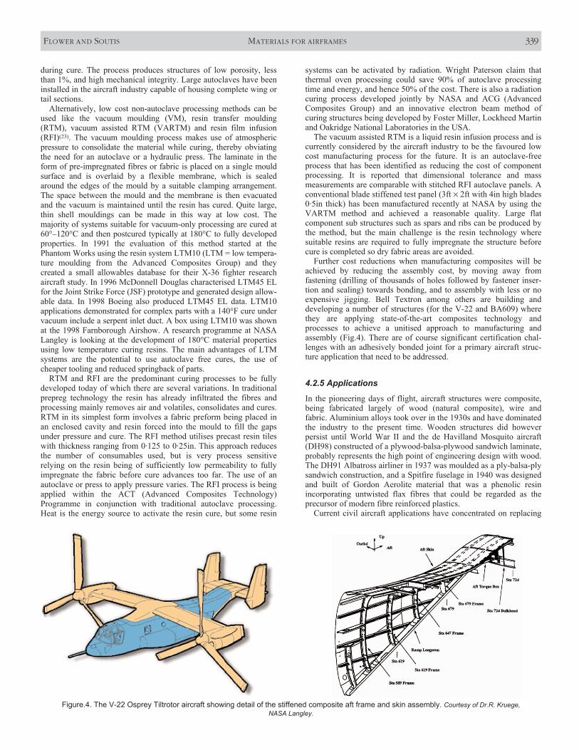
Further cost reductions when manufacturing composites will beachieved by reducing the assembly cost, by moving away fromfastening (drilling of thousands of holes followed by fastener inser-tion and sealing) towards bonding, and to assembly with less or noexpensive jigging. Bell Textron among others are building anddeveloping a number of structures (for the V-22 and BA609) wherethey are applying state-of-the-art composites technology andprocesses to achieve a unitised approach to manufacturing andassembly (Fig.4). There are of course significant certification chal-lenges with an adhesively bonded joint for a primary aircraft struc-ture application that need to be addressed.
4.2.5 Applications
In the pioneering days of flight, aircraft structures were composite,being fabricated largely of wood (natural composite), wire andfabric. Aluminium alloys took over in the 1930s and have dominatedthe industry to the present time. Wooden structures did howeverpersist until World War II and the de Havilland Mosquito aircraft(DH98) constructed of a plywood-balsa-plywood sandwich laminate,probably represents the high point of engineering design with wood.The DH91 Albatross airliner in 1937 was moulded as a ply-balsa-plysandwich construction, and a Spitfire fuselage in 1940 was designedand built of Gordon Aerolite material that was a phenolic resinincorporating untwisted flax fibres that could be regarded as theprecursor of modern fibre reinforced plastics.
Current civil aircraft applications have concentrated on replacing
FLOWER AND SOUTIS MATERIALS FOR AIRFRAMES 339
Figure.4. The V-22 Osprey Tiltrotor aircraft showing detail of the stiffened composite aft frame and skin assembly. Courtesy of Dr.R. Kruege, NASA Langley.

the secondary structure with fibrous composites where the reinforce-ment media has either been carbon, glass, Kevlar or hybrids of these.The matrix material, a thermosetting epoxy system, is either a 125°Cor 180°C curing system with the latter becoming dominant becauseof its greater tolerance to environmental degradation. Typical exam-ples of the extensive application of composites in this manner are theBoeing 757, 767 and 777 and from Europe the Airbus A310, A320,A330 and A340 airliners. The A310 carries a vertical stabiliser(8·3m high by 7·8m wide at the base), a primary aerodynamic andstructural member fabricated in its entirety from carbon composite(now £10–20/kg for large tow high strength fibre) with a total weightsaving of almost 400kg when compared with the Al alloy unit previ-ously used. In addition the CFRP fin box comprises only 95 parts,excluding fasteners, compared with 2076 parts in the metal unit, thusmaking it easier to produce. The A320 has extended the use ofcomposites to the horizontal stabiliser, in addition to the plethora ofpanels and secondary control surfaces, leading to a weight saving of800kg over Al alloy skin construction. As an indication of thebenefit of such weight saving it has been estimated that 1kg weightreduction saves over 2,900litres of fuel per year. Larger amounts ofFRPs are used in the bigger A330, A340 models and of course in theA380 super jumbo airliner that is currently being built by the Airbusconsortium (Fig. 3). GKN Aerospace Services at Cowes, Isle ofWight, UK is committed to produce some 70 trailing edge panels forthe wings of each of the new 550-seat A380s. If predictions that upto 600 A380s will be sold are realised, the long-term contract valueto GKN Aerospace could eventually top US$600m. The wingtrailing edge panels are made of glass and carbon fibre reinforcedplastics using a new resin film infusion method (RFI), in which resinfilm, interleaved between glass and carbon fabric layers when thelaminate is laid up, melts when heat is applied. Melted low-viscosityresin migrates easily through the thickness of the laminate where itcures to form the final component. Heat can be applied easily with asimple oven or with heated mould tools, so avoiding the need to usean expensive autoclave. Taking the autoclaving step out, and nothaving to deal with the more usual pre-impregnated glass/carbonmaterials, makes it quicker and cheaper to produce composite parts.
In two small aircraft, attempts have been made to apply compos-ites to almost the entire plane; these are the Lear Fan fabricated inNorthern Ireland (not successful though for technical and commer-cial reasons) and the US Beech Starship. Dowty Propellers, a part ofSmiths Aerospace, design and manufacture composite bladedpropellers for transport aircraft such as the Lockheed Martin C-130Jand Bombardier Q400 Dash 8. The blades show considerable weightsaving, damage tolerance and performance gains, with an excellentfatigue life over metal construction. The blade design is of mono-coque construction with carbon fibre spars and a carbon /glass braidskin over a polyurethane foam core. Erosion protection is providedby a polyurethane elastomer coating. Blades are made by resintransfer moulding (RTM) and are use carbon and glass reinforce-ment with a polyurethane foam core and epoxide resin matrix. Over17,500 blades have been produced in the dedicated manufacturingfacility and have accumulated 100 million blade flying hours.
Composites have been used in Bell helicopters (Dallas, Fort Worth,USA) since the 1980s, following their ACAP (advanced compositesairframe programme) when they were able to achieve a 20% reduc-tion in weight on metallic airframes. All blades on their newer vehi-cles (412, 407, 427, 214, 609, OH-58D, V-22) are all composite. TheV-22 Osprey tilt-rotor has an all-composite wing, chosen for its stiff-ness critical design, which was only possible in composites at lowenough weight (Fig.4). Early demonstrators (from 1960s onwards)did not meet expectations until composites were available. The skinsof the V-22 wing are I-stiffened with co-bonded spars and bolted onribs (the civil 609 version will use bonded ribs). The pylon supportspindle is currently filament wound but it is planned to fibre placethis part. Over 60% of the whole vehicle weight is carbon composite,plus a further 12% in GRP. The V-22 uses tape laying, hand lay-upand filament winding for most of the composite construction but is
moving to fibre placement for the 609 civil version. Mechanicalfastening features heavily in the composite structure, with some 3,000each side of the wing. This fastening is done by manual drilling withtemplates, but they are looking towards the use of automated drillingand probably involving water jet cutting(17).
The design and manufacture of a low-cost composite wing by Bellhelicopters is an advanced technology demonstrator civil wing forthe 609 tiltrotor. The project seeks a 10% reduction in non-recurringcosts and 50% reduction in running costs compared with the V-22PMC design. The skins are hat stiffened and the material isIM7/ET1. The V-22 uses IM7/3501-5 carbon fibre/epoxy system andthe 609 will likely use the 3900 Toray interleave material as used onthe Boeing 777. The tension and compression skins are designed to4,700µε and tested to 4,200µε† static (1·2 × limit). Testing currentlyproceeds in spectrum fatigue for 10,000hrs (one lifetime) at AFRLfollowed by inspection and then impact, then a static test to 1·5 ×limit load. Many sub-component tests have been performed,including three stringer panels, hot/wet specimens for safety factorsand bonded rib/skin elements. Bond validation is by basic pulse-echo technique and quality control. The rotor uses a composite gripand yoke and the blade design is very similar to that of modernWestland helicopter blades.
Other examples where composites will be extensively applied inthe future, are the military cargo Airbus A400M and the tail of the C-17 (USA). The latter is part of an AFRL funded demonstratorproject ‘Manufacturing 2005’ valued at $50m. A 62ft demonstratorhas been successfully completed yielding 4,300 fewer parts(including fasteners), weight reduced by 20% (260kg) and cost by50%, compared with the existing metal tail. Ribs are still metal, butmuch reduced in section and designed only to take torque. Thecomposite skin and C-spars carry all other loads. Another recentprogramme funded by NASA, the Advanced Subsonic Transport(AST), included the development of a large stitched composite wingat the Boeing Long Beach plant. This part was 45ft long with stitchedmultiple layers of non-crimped fabric (NCF) with Kevlar throughthickness reinforcement. Target for the project was 25% cost reduc-tion on a composite skin/metallic substructure design. The compositematerial was the basic AS4/3501-6 with a slight modification (notrevealed)(17). Although this project was primarily a manufacturingtechnology demonstration many of the manufacturing/assemblyconcepts developed could be used in future aircraft construction.
Without exception, all agile fighter aircraft currently beingdesigned or built in the USA and Europe (e.g. JSF, EFA) contain inthe region of 40% of composites in the structural mass, coveringsome 70% of the surface area of the aircraft. The essential agility ofthe aircraft would be lost if this amount of composite material wasnot used, because of the consequential mass increase. Many of thematerials, processes and manufacturing methods discussed earlier inthe paper have been implemented in their construction. The wing,vertical stabiliser and forward fuselage of the Eurofighter (Typhoon)are mainly CFRP, while the centre and aft fuselage have compositeskins over aluminium and titanium substructure. A high-strength,damage-tolerant fibre/resin system is used, and the wing’s multiplecarbon-fibre spars are co-bonded to the lower skins. The airframe isdesigned for a 6000hr life.
Carbon fibre composites are here to stay in terms of future aircraftconstruction since significant weight savings can be achieved. Forsecondary structures weight savings approaching 40% are feasibleby using composites instead of light metal alloys, while for primarystructures such as wings and fuselages 20% is more realistic. Themain challenges restricting their use are material and processingcosts, damage tolerance, repair and inspection, dimensional toler-ance and conservatism associated with uncertainties about relativelynew and sometimes variable materials.
Another interesting relatively new field of development in themilitary sphere is that of ‘stealth’, a concept that requires the
340 THE AERONAUTICAL JOURNAL JUNE 2003
† µε is a unit of microstrain (10–6).

designer to achieve the smallest possible radar cross section (RCS),to reduce the chances of early detection by defending radar sets. Anycomplex shape is much easier to form in composites than in metaland radar absorbent material (RAM) can be incorporated into lami-nated composite structures.
5.0 SUMMARYReduction in cost and weight will continue to dominate materialsdevelopments for airframes. Metallic materials will remain majorstructural materials with advanced processing and component manu-facturing methods playing a key role. The trend for polymer compos-ites to form a larger fraction of the airframe weight will continue in aprogressive manner. Materials and processes will be developed tooffer mass and part reduction, complex shape manufacture, reducedscrap, improved fatigue life, design optimisation and generallyimproved corrosion resistance. Modelling will continue to grow inaccuracy and importance in every aspect of airframes from design ofmaterial, material processing, manufacture and service propertyprediction. This will significantly reduce the amount of experimentaldevelopment work and cut the time from concept to final design.
REFERENCES1. QUIST, W.E, NARAYANAN, G.H. and WINGERT, A.L. Aluminium-
Lithium alloys for aircraft structure — An overview, 1984, Aluminium-Lithium Allys II. SANDERS, T.H. and STARKE E.A. (Eds), Met. SocAIME, pp 313-334.
2. WILM, A. Metallurgie, Zeitschrift für die Gesamte Hüttenkunde:Aufbereitung-Eisen-und Matallhüttenkunde-Metallographie, 8, 1911,BORCHERS, W. and WUST, F. (Eds) Reproduced in English in MARTINJ.W. Precipitation Hardening, 1998, 2nd ed, Butterworth Heineman.
3. STARINK, M.J., SINCLAIR, I., REED P.A.S. and P.J. GREGSON, Predictingstructural performance of heat-treatable alloys, in Aluminium Alloys:Their Physical and Mechanical Properties, 2000, STARKE, E.A.,SANDERS T.H. and CASSADA W.A. (Eds) (Proc. ICAA-7), Mater, Sci,Forum, 331-337, pp 97-110.
4. HEINZ, A., HASZLER A., KEIDEL C., MOLDENHAUER, S., BENEDICTUS, R.and MILLER, W.S. Recent developments in aluminium alloys for aero-space applications, 2000, Mat Sci Eng A280, pp 102-107.
5. WOODWARD, R. Where next wrought aluminium alloys? AluminiumToday, December 1997, pp 21-24.
6. THOMAS, W.M., NICHOLAS, E.D., WATTS, E.R. and STAINES, D.G. Fric-tion based welding technology for aluminium, Aluminium Alloys, TheirPhysical and Mechanical Properties, 2002, 3, (eds). GREGSON, P.J. andHARRIS S.J. (Eds), Trans Tech Publications, pp 1543-1548.
7. KINLOCH, A.J. Adhesion and Adhesives: Science and Technology, 1987,Chapman and Hall, London.
8. GRIMES, R., DASHWOOD, R.J. and FLOWER, H.M. High strain ratealuminium alloys: the way forward? 2001, Materials Science Forum357-359, pp 339-344.
9. Stanford Materials WebSite http://www.stanfordmaterials.com/sc.htmlon 26 July 2000).
10. GRIMES, R., RICHARD DASHWOOD, R.J., and FLOWER, H.M. Towards superplasticity in AA 6XXX alloys.
11. LEE, P.D., ATWOOD, R.C., DASHWOOD, R.J and NAGAUMI, H. Modelingof porosity formation in direct chill cast aluminium-magnesium alloy,2002, Mat Sci Eng, A328, pp 213-222.
12. KENNERKNECHT, S. Structural aerospace aluminium investment castings10-year (1990-2000) supply and demand market evolution. ProcAeroMat 2001, Long Beach, California, ASM.
13. FROES, S.H. Developments in titanium applications, October 1995,Light Metal Age, pp 6-8.
14. OKURA, Y. Titanium sponge production technology, 1996, In Titanium‘95: Science and Technology, 2, pp 1427-1437, BLENKINSOP, P.A.,EVANS, W.J. and FLOWER, H.M. (Eds) Inst Materials, London.
15. CHEN, G.Z., FRAY, D.J. and FARTHING T.W. Direct electrochemicalreduction of titanium dioxide to titanium in molten calcium chloride,2000, Nature, 407, pp 361-364.
16. KELLY, A. (Ed), Concise encyclopaedia of composite materials, Perg-amon, 1994.
17. Aerospace composite structures in the USA, Report for the Interna-tional Technology Service (Overseas Missions Unit) of the DTI, UK.1999.
18. RAWAL, S. Metal-matrix composites for space applications. J Mats,April 2001, 14-17.
19. VLOT, A. and GUNNICK, J.W. (Eds), Fibre Metal Laminates, 2001,Klewer, Dordrecht.
19. MATTHEWS, F.L and RAWLINGS, R.D. Composite Materials: Engi-neering and Science, 1994, Chapman & Hall.
20. HULL, D. An Introduction to Composite Materials, 1987, CambridgeUniversity Press.
21. MATTHEWS, F.L, DAVIES, G.A.O., HITCHINGS, D. and SOUTIS, C. FiniteElement Modelling of Composite Materials and Structures, 2000,Woodhead Publishing.
22. GUTOWSKI, T.G. (Ed) Advanced composites manufacturing, 1997, JohnWiley & Sons.
FLOWER AND SOUTIS MATERIALS FOR AIRFRAMES 341