Embed Size (px)
Citation preview

MATERIALS AND PROCESSING TECHNIQUES FOR SUPERCAPACITORS

________________________________________________________________________
SYNTHESIS AND PROCESSING TECHNIQUES OF ADVANCED ELECTRODE
MATERIALS FOR SUPERCAPACITOR APPLICATIONS
By JORDAN MILNE, B.Eng
A Thesis Submitted to the School of Graduate Studies in Partial Fulfilment of the
Requirements for the Degree Master of Applied Science
McMaster University © Copyright by Jordan Milne, April 2019

ii
McMaster University MASTER OF APPLIED SCIENCE (2019) Hamilton, Ontario
(Materials Science & Engineering)
TITLE: Synthesis and Processing Techniques of Advanced Electrode Materials for
Supercapacitor Applications
AUTHOR: Jordan Milne, B.Eng. (McMaster University)
SUPERVISOR: Dr. Igor Zhitomirsky, Distinguished Engineering Professor, Ph.D., P.Eng.
NUMBER OF PAGES: 108

iii
Abstract
In a world that relies heavily on electricity and portable energy, the development of
high performing energy storage devices is crucial. The ongoing push for energy storage
devices such as batteries and supercapacitors to store more energy and charge/discharge
faster has become exponentially stronger over the past decade. In order to meet the high
demands, new materials and processing techniques must be developed.
A particle extraction through the liquid-liquid interface (PELLI) technique was used
with a versatile extracting molecule, Octyl Gallate (OG). It was found that OG was able to
extract a variety of materials including oxides, oxyhydroxides, and pure silver. The
advantage of PELLI is that it circumvents the drying stage that occurs in many electrode
synthesis techniques where metal oxides are synthesized in aqueous then dried and mixed
with conductive additives dispersed in organic solvent. This drying stage causes a
practically irreversible agglomeration which hinders mixing with conductive additives as
well as reduces the surface area of the material, limiting its electrochemical performance.
Using hydroxamates such as octanohydroxamic acid and bufexamac, a novel PELLI
technique was developed based on the use of OHA as an extracting agent as well as a
capping agent.
In addition, a preliminary investigation was started on advanced negative electrode
material for supercapacitors. FeOOH-based electrodes exhibit high capacitance but low
cyclic stability. Zn2+ ions were introduced during synthesis forming a doped Zn/FeOOH
electrode which showed a significant increase in cyclic stability.

iv
Acknowledgements
Firstly, I would like to recognize my supervisor Dr. Igor Zhitomirsky for his kind
demeanour and seemingly endless pool of knowledge in chemistry and material science.
My lab mates Ryan Poon, Ricardo Silva, Amanda Clifford, and Aseeb Syed thank
you for making everyday a little more entertaining. I am very grateful to my love Kathryn
Passalent for giving me a wonderful life outside of graduate school.
Finally, I would like to thank my Mom, Dad, and sister for their endless support
and encouragement.
Big shout out to my #bois – Jon Remacka, Zark Fukerderg Hansen, Quinn Lees,
Poot Clarke and Garrett the ferret.

v
Table of Contents
Abstract .............................................................................................................................. iii Acknowledgements ............................................................................................................. iv
Table of Figures ................................................................................................................ vii
Table of Tables ................................................................................................................... ix Table of Abbreviations and Symbols ................................................................................... x
Declaration of Academic Achievement ............................................................................ xii Chapter 1: Introduction .................................................................................................... 1
Chapter 2: Literature Review ........................................................................................... 5
2.1 Fundamentals of Conventional Capacitors ........................................................... 5
2.2 Types of Supercapacitors ...................................................................................... 8
2.2.1 Electrochemical Double-Layer Capacitors .................................................... 8
2.2.2 Pseudocapacitors .......................................................................................... 11
2.3 Electrode Materials for Supercapacitors ............................................................. 14
2.3.1 MnO2 ............................................................................................................ 15 2.3.2 Mn3O4 .......................................................................................................... 17
2.3.3 FeOOH ......................................................................................................... 19
2.3.4 Other Metal Oxides ...................................................................................... 20
2.3.5 Carbon Materials .......................................................................................... 24
2.3.6 Conductive additives .................................................................................... 25
2.4 Asymmetric Supercapacitors ............................................................................... 27 2.5 Mass Loading ...................................................................................................... 30
2.6 Fabrication Methods ............................................................................................ 30 2.6.1 Electrophoretic Deposition .......................................................................... 31
2.6.2 Chemical Bath Deposition ........................................................................... 33
2.6.3 Heterocoagulation ........................................................................................ 34
2.6.4 Particle Extraction Through the Liquid-Liquid Interface ............................ 36
Chapter 3: Problem Statements and Objectives ............................................................. 39
Chapter 4: Experimental Procedures ............................................................................. 40

vi
4.1 Chemicals and Materials ..................................................................................... 40 4.2 Synthesis of Electrode Materials Using Octyl Gallate for PELLI ...................... 40
4.3 Synthesis of Electrode Materials Using Octanohydroxamic Acid for PELLI .... 42 4.4 Synthesis of Zn/FeOOH Electrode Materials ...................................................... 42
4.5 Characterization of Electrode Materials .............................................................. 43 4.5.1 SEM ............................................................................................................. 43
4.5.2 FTIR and XPS .............................................................................................. 44 4.5.3 XRD ............................................................................................................. 44
4.6 Fabrication of Electrodes .................................................................................... 45
4.7 Electrochemical Characterization of Electrodes ................................................. 45
4.7.1 Cyclic Voltammetry ..................................................................................... 46
4.7.2 Electrochemical Impedance Spectroscopy................................................... 48
4.7.3 Galvanostatic Charge-Discharge ................................................................. 50
Chapter 5: Surface Modification and Dispersion of Ceramic Particles Using Liquid-Liquid Extraction Method for Application in Supercapacitor Electrodes ......................... 52
5.1 Authors Contribution ........................................................................................... 52
Chapter 6: Application of Octanohydroxamic Acid for Liquid-Liquid Extraction of Manganese Oxides and Fabrication of Supercapacitor Electrodes .................................... 59
Chapter 7: Phase Transfer of Oxide Particles Using Hydroxamic Acid Derivatives and Application for Supercapacitors......................................................................................... 68 Chapter 8: Development of a Cyclically Stable FeOOH Negative Electrode Using Zn as a Dopant 75
8.1 Introduction ......................................................................................................... 75
8.2 Results and Discussion ........................................................................................ 77 8.3 Conclusion ........................................................................................................... 83
Chapter 9: Final Conclusions and Future Work ............................................................ 84 References .......................................................................................................................... 86

vii
Table of Figures
Figure 1-1: Ragone plot displaying power and energy densities of energy storage
devices[1]. ............................................................................................................................ 2
Figure 2-1: Diagram of a simple electrostatic capacitor. ..................................................... 5
Figure 2-2: Models of the double-layer a) Helmholtz model, b) Gouy-Chapman model, and
c) Stern model ...................................................................................................................... 9
Figure 2-3: Grahame’s representation of the double-layer structure defining different
regions for adsorption of hydrated cations and less hydrated anions. ............................... 10
Figure 2-4: Different types of pseudocapacitive behaviour: (a) underpotential deposition,
(b) redox pseudocapacitance, and (c) intercalation pseudocapacitance[12]. ..................... 12
Figure 2-5: The potential windows of a variety of pseudocapacitive materials in aqueous
electrolyte[13]. ................................................................................................................... 15
Figure 2-6: Crystal structures of α-, β-, γ-, δ-, and λ-MnO2[17]. ...................................... 17
Figure 2-7: Cycling behavior of the Mn3O4 electrode[22]. .............................................. 18
Figure 2-8: Representative resistivity of V2O5, VO2, and V2O3[50]. ................................ 23
Figure 2-9: Specific capacitance over 1000 cycles of pure NiO and graphene/NiO[67]. . 26
Figure 2-10: Asymmetric supercapacitor publications since 2006[71]. ............................ 28
Figure 2-11: Specific capacitance of selected anode and cathode materials[69]. .............. 29
Figure 2-12: Schematic diagram of the simple EPD process[82]. ..................................... 32
Figure 2-13: Synthesis process for heterocoagulation using MWCNT and MnO2[92]. .... 35
Figure 2-14: Schematic of (a) precipitation of particles in aqueous solution, (b,c) different
stages in extraction[96]. ..................................................................................................... 36

viii
Figure 2-15: Nyquist plot of complex impedance for MnO2-MWCNT electrodes prepared
(a) without extraction and (b–d) by PELLI using (b) 16-phosphonohexadecanoic acid, (c)
octadecylphosphonic acid, and (d) stearic acid extractors[99]. ......................................... 38
Figure 4-1: A typical CV for supercapacitors displayed in linear form to display the effect
increasing the potential (black) induces current (blue)[100]. ............................................ 47
Figure 4-2: Typical Nyquist plot for supercapacitors. ....................................................... 49
Figure 4-3: GCD of a supercapacitor[100]. ....................................................................... 51
Figure 8-1: (A) CVs at scan rates of (a) 2, (b) 10, and (c) 20 mV s-1, (B) Cs and Cm,
calculated from the CV data for FeOOH-MWCNT composites. ...................................... 77
Figure 8-2: (A) Nyquist plot of complex impedance and frequency dependences of (B) C’s
and (C) C’’s calculated from the impedance data for FeOOH-MWCNT composites. ....... 78
Figure 8-3: Capacitance retention over 1000 CV cycles at 50 mV s-1 for the FeOOH-
MWCNT electrode. ............................................................................................................ 79
Figure 8-4: (A) CVs at scan rates of (a) 2, (b) 10, and (c) 20 mV s-1, (B) Cs and Cm,
calculated from the CV data for Zn/FeOOH-MWCNT composites. ................................. 80
Figure 8-5: (A) Nyquist plot of complex impedance and frequency dependences of (B) C’s
and (C) C’’s calculated from the impedance data for Zn/FeOOH-MWCNT composites. .. 81
Figure 8-6: X-ray diffraction patterns of (A) FeOOH (B) Zn/FeOOH .............................. 82
Figure 8-7: Capacitance retention over 1000 CV cycles at 5 mV s-1 for the FeOOH-
MWCNT electrode. ............................................................................................................ 83

ix
Table of Tables
Table 2-1: Types of pseudocapacitive systems and their corresponding Nernst type
equations[9]. ....................................................................................................................... 14
Table 4-1: Table of Materials used. ................................................................................... 40

x
Table of Abbreviations and Symbols Abbreviations
[Ox] Concentration of Oxidized Species
[Red] Concentration of Reduced Species
AC Activated Carbon
CBD Chemical Bath Deposition
CNT Carbon Nanotubes
CV Cyclic Voltammetry
EDLC Electrostatic Double-Layer Capacitor
EIS Electrochemical Impedance Spectroscopy
EPD Electrophoretic Deposition
ESR Equivalent Series Resistance
FTIR Fourier Transform Infrared Spectroscopy
GCD Galvanostatic Charge-Discharge
IR loss/drop I – current, R – resistance
LLI Liquid-Liquid Interface
MWCNT Multi-Wall Carbon Nanotubes
PELLI Particle Extraction through the Liquid-Liquid Interface
rGO Reduced Graphene Oxide
SCE Saturated Calomel Electrode
SEM Scanning Electron Microscopy
XPS X-Ray Photoelectron Spectroscopy
XRD X-Ray Diffraction

xi
Symbols
°C Degrees Celsius
A Area
C Capacitance
d distance
F Farad
g Gram
I Current
k Boltzmann Constant
Q Charge
𝐑𝐑� Gas Constant
R Resistance
T Temperature
V Volt
W Watt
Z Impedance

xii
Declaration of Academic Achievement
This dissertation was used to fulfill the requirements of the degree: Master of Applied
Science. The major research project ran from May 2017 to April 2019. The content of this
dissertation was covered in three papers in which I was first author, published in peer-
reviewed journals:
1. J. Milne and I. Zhitomirsky, “Application of octanohydroxamic acid for liquid-
liquid extraction of manganese oxides and fabrication of supercapacitor electrodes,”
J. Colloid Interface Sci., vol. 515, pp. 50–57, 2018.
2. J. Milne, R. M. E. Silva, Z. Z. Wang, and I. Zhitomirsky, “Phase transfer of oxide
particles using hydroxamic acid derivatives and application for supercapacitors,”
Ceram. Int., vol. 45, no. 2, pp. 2498–2503, 2018.
3. J. Milne, R. Marques Silva, and I. Zhitomirsky, “Surface modification and
dispersion of ceramic particles using liquid-liquid extraction method for application
in supercapacitor electrodes,” J. Eur. Ceram. Soc., IN PRESS
I also contributed to four additional papers, published in peer-reviewed journals, that will
not be covered in this dissertation:
1. R. M. E. Silva, R. Poon, J. Milne, A. Syed, and I. Zhitomirsky, “New developments
in liquid-liquid extraction, surface modification and agglomerate-free processing of
inorganic particles,” Adv. Colloid Interface Sci., vol. 261, pp. 15–27, 2018.
2. M. S. Ata, R. Poon, A. M. Syed, J. Milne, and I. Zhitomirsky, “New developments
in non-covalent surface modification, dispersion and electrophoretic deposition of
carbon nanotubes,” Carbon N. Y., vol. 130, pp. 584–598, 2018.

xiii
3. M. S. Ata, J. Milne, and I. Zhitomirsky, “Fabrication of Mn3O4–carbon nanotube
composites with high areal capacitance using cationic and anionic dispersants,” J.
Colloid Interface Sci., vol. 512, pp. 758–766, 2018.
4. R. M. Silva, B. S. Noremberg, N. H. Marins, J. Milne, I. Zhitomirsky, and N. L. V
Carreño, “Microwave-assisted hydrothermal synthesis and electrochemical
characterization of niobium pentoxide / carbon nanotubes composites,” J. Mater.
Res., pp. 1–8, 2018.
5. Z.Wang, A. Clifford, , J. Milne, I. Zhitomirsky, “Colloidal-electrochemical
fabrication strategies for linear polyethylenimine composites,” J. Colloid Interface
Sci, SUBMITTED

M.A.Sc Thesis – Jordan Milne; McMaster University – Materials Science & Engineering.
1
Chapter 1: Introduction
As a result of the escalating energy demands of modern society paired with intensifying
environmental concerns, it has become necessary to discover and further develop advanced
materials for energy storage systems. Some of the most practical and effective technologies
for storage and conversion of electrochemical energy are electrochemical supercapacitors,
batteries, and fuel cells.
Electrochemical supercapacitors, also called ultracapacitors or supercapacitors, are
energy storage devices that bridge the gap between conventional capacitors and batteries.
Supercapacitors have a power density above that of a battery while achieving an energy
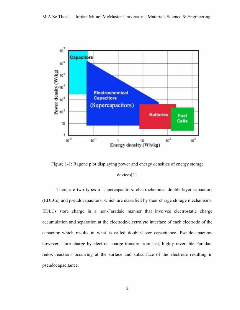
density above that of conventional capacitor, as seen in Figure 1-1[1]. This unique
combination of power and energy density allows supercapacitors to be used in applications
where neither battery nor capacitor are suitable, as well as applications where hybrid
capacitor-battery systems are necessary.
M.A.Sc Thesis – Jordan Milne; McMaster University – Materials Science & Engineering.
2
Figure 1-1: Ragone plot displaying power and energy densities of energy storage
devices[1].
There are two types of supercapacitors: electrochemical double-layer capacitors
(EDLCs) and pseudocapacitors, which are classified by their charge storage mechanisms.
EDLCs store charge in a non-Faradaic manner that involves electrostatic charge
accumulation and separation at the electrode/electrolyte interface of each electrode of the
capacitor which results in what is called double-layer capacitance. Pseudocapacitors
however, store charge by electron charge transfer from fast, highly reversible Faradaic
redox reactions occurring at the surface and subsurface of the electrode resulting in
pseudocapacitance.

M.A.Sc Thesis – Jordan Milne; McMaster University – Materials Science & Engineering.
3
The material in a supercapacitor electrode that contributes to charge storage is
termed as the active material. A variety of active materials can be used for positive and
negative electrodes of supercapacitors. High surface area carbon derivatives have
dominated as active materials for EDLC type supercapacitors, as the amount of charge is
proportional to surface area. Whereas transition metal oxides and hydroxides, as well as
conducting polymers achieve exceptional pseudocapacitive performance and are becoming
increasingly common in supercapacitors. Unfortunately, most oxides and hydroxides have
intrinsically low electrical conductivity so high capacitances can only be achieved by thin
film electrodes. In addition, metal oxides and hydroxides tend to agglomerate during drying
after particle synthesis, resulting in the particle surface area becoming inaccessible to
electrolyte and other electrode material additives.
Over the last decade, the majority of supercapacitor research and improvements
have been on positive electrode materials, leaving the negative electrode to become the
limiting factor of device performance. Activated carbon is a common negative electrode
for supercapacitors[2] but it has a lower capacitance compared to the positive electrode in
addition to being expensive. FeOOH is a promising negative electrode material due to its
high capacitance[3] but its poor cycle life renders it impractical for commercial application.
The objective of this research was to develop a novel processing technique for the
synthesis of non-agglomerated particles to enhance supercapacitor performance as well as
to develop an advanced negative electrode material for asymmetric supercapacitors all with
high active mass loadings. An innovative colloidal processing technique was developed
that used a multifunctional molecule that acted as a capping agent and a dispersing agent.

M.A.Sc Thesis – Jordan Milne; McMaster University – Materials Science & Engineering.
4
The conceptually new approach resulted in reduced particle size and improved mixing with
conductive additives giving exceptional electrochemical performance. In addition, a new
negative electrode material was developed via doping FeOOH with Zn that exhibited
impressive cyclic stability.

M.A.Sc Thesis – Jordan Milne; McMaster University – Materials Science & Engineering.
5
Chapter 2: Literature Review 2.1 Fundamentals of Conventional Capacitors
In energy storage applications, capacitors predate the invention of the battery. The
first capacitor was built at the University of Leyden in the mid 1700s using a glass jar
coated inside and out with silver foil[4]. A brief review of the fundamentals of simple
conventional capacitors is necessary as the governing equations and principles carry into
the more complex capacitor types. Figure 2-1 shows a simple capacitor that consists of two
parallel conducting plates and a dielectric in between[5].
Figure 2-1: Diagram of a simple electrostatic capacitor.
In order for electrostatic charge to develop on the plate/electrodes of the capacitor,
work must be done by an external driving force such as applying a potential difference.

M.A.Sc Thesis – Jordan Milne; McMaster University – Materials Science & Engineering.
6
Initially, the net charge between the plates of the capacitor is zero. In Figure 2-1 a battery
provides an electromotive force generating a flow of electrons from one of the electrodes
of the capacitor to the positive terminal of the battery, making that electrode positively
charged. Simultaneously, electrons flow from the negative terminal of the battery and
accumulate on the other electrode of the capacitor, making that electrode negatively
charged. The charging continues until the potential between the plates of the capacitor is
equal to the applied potential from the battery and the charge on each electrode of the
capacitor is equal and opposite. The ratio between the electric charge on each electrode (Q),
and the potential difference between the electrodes (V), is denoted as capacitance (C), as
seen in Eq. 2.1.
𝐶𝐶 =𝑄𝑄𝑉𝑉
=𝜀𝜀0𝜖𝜖𝑟𝑟𝐴𝐴𝑑𝑑
(2.1)
For a simple parallel plate capacitor as shown above, capacitance is dependent on the area
(A) of the electrodes, the permittivity of free space (ε0), the dielectric constant of the
material between the plates (εr), and the distance (d) between the two electrodes.
To calculate the work done by the potential to store charge in a capacitor, an
equation can be developed using the relation between the amount of incremental work (dW)
required for an incremental change in charge (dQ):
𝑑𝑑𝑑𝑑 = 𝑉𝑉𝑑𝑑𝑄𝑄 (2.2)

M.A.Sc Thesis – Jordan Milne; McMaster University – Materials Science & Engineering.
7
The integral of this equation results in the amount of energy the capacitor can hold. To
simplify integration, we can use the relation between charge, capacitance, and potential and
remove capacitance from inside the integral because capacitance remains constant which
results in:
𝐸𝐸 = �𝑑𝑑𝑑𝑑 = �𝑉𝑉𝑑𝑑𝐶𝐶𝑉𝑉 = 𝐶𝐶 �𝑉𝑉𝑑𝑑𝑉𝑉 = �12�𝐶𝐶𝑉𝑉2 (2.3)
In addition, the power density of a capacitor can be written as:
𝑃𝑃 =𝑉𝑉2
4𝑅𝑅𝐸𝐸𝐸𝐸𝐸𝐸(2.4)
Where RESR is the equivalent series resistance (ESR). It is clear from these equations that
both power and energy density can be increased by increasing the operating voltage. In
addition, energy density can be increased by increasing the capacitance. Regarding the
deliverable power supplied by the capacitor, the power density can also be increased by
reducing the ESR. In summary, by increasing the capacitance as well as the operating
voltage and reducing the resistance, energy and power density can be increased.

M.A.Sc Thesis – Jordan Milne; McMaster University – Materials Science & Engineering.
8
2.2 Types of Supercapacitors
2.2.1 Electrochemical Double-Layer Capacitors
EDLCs differ from pseudocapacitors due to the different charge storage
mechanisms[6]. Similar to conventional electrostatic capacitors, EDLCs also store charge
in a non-Faradaic method, meaning there is no charge transfer or redox reactions[7].
EDLCs are comprised of two electrodes which are typically made of high surface area
carbon materials such as activated carbon. The two electrodes are physically separated by
an ion permeable separator but remain connected ionically via an electrolyte. The
electrolyte consists of both positive and negative ions dissolved in a solvent such as water.
When a voltage is applied across the electrodes of an EDLC, ‘double-layers’ are formed at
each electrode involving the charge on the surface of the electrode and solvated dissolved
ions of the opposite charge in the electrolyte. A monolayer of solvent molecules, such as
water, separate these two layers and charge is stored electrostatically. EDLCs work on the
same principle as conventional capacitors but take advantage of the astonishingly large
surface area of activated carbon and the nanoscale distance between the electrode surface
and electrolyte ion which in this case would be the diameter of a water molecule.
Regarding modelling the double-layer phenomenon, there have been a series of
models through history that have been accepted then improved upon which eventually led
to the most correct, Grahame Model[8]. The first model of the double-layer was developed
by Helmholtz, Figure 2-2(a), which illustrates the distribution of opposite charges, quasi-
2-dimensionally, at the electrode-electrolyte interface. Applying a potential causes a

M.A.Sc Thesis – Jordan Milne; McMaster University – Materials Science & Engineering.
9
controllable amount of charge buildup on the electrode surface due to an excess or
deficiency of electrons and a corresponding accumulation of oppositely charged ions in
solution complete the double-layer. Figure 2-2(b) is the Gouy-Chapman model, which
introduced two modifications, (1) assume the electrolyte ions are point charges, (2) the
double-layer would be subject to thermal fluctuations according to the Boltzmann
principle[9]. The next development in the double-layer theory was by Stern and is shown
in Figure 2-2(c). In his model, Stern combined the Helmholtz and Gouy-Chapman model
to overtly define two regions of ion distribution, the diffuse layer/region and the
compact/Helmholtz layer.
Figure 2-2: Models of the double-layer a) Helmholtz model, b) Gouy-Chapman model,
and c) Stern model[9]
The Helmholtz layer containing a compact array of ions has a capacitance of CH. The
remaining ionic charge density past the Helmholtz layer is termed as the diffuse region,
having a capacitance of Cdiff. Combining these capacitances results in the overall double-
layer capacitance (Cdl), governed by:

M.A.Sc Thesis – Jordan Milne; McMaster University – Materials Science & Engineering.
10
1𝐶𝐶𝑑𝑑𝑑𝑑
=1𝐶𝐶𝐻𝐻
+1
𝐶𝐶𝑑𝑑𝑑𝑑𝑑𝑑𝑑𝑑(2.5)
The Stern model was further improved by Grahame, as seen in Figure 2-3, who made an
important distinction between an inner and outer Helmholtz layer due to the different
distances of closest approach at the electrode surface for cations and anions.
Figure 2-3: Grahame’s representation of the double-layer structure defining different
regions for adsorption of hydrated cations and less hydrated anions.[9]
Due to the fact that most cations have a stronger ion-solvent interaction, they retain a large
solvation shell which hinders the accumulation of cations to the electrode interface
increasing their distance of closest approach. This leads to anion distance of closest
approach to usually be smaller than that of a cation’s, causing the inner layer capacitance

M.A.Sc Thesis – Jordan Milne; McMaster University – Materials Science & Engineering.
11
of positively charged electrodes to typically be higher than that of a corresponding
negatively charged electrode surface[9].
2.2.2 Pseudocapacitors
Pseudocapacitors utilize extremely rapid and reversible Faradaic charge transfer
reactions between the active material of the electrode and the ions from the electrolyte
which gives a much larger energy density than that of EDLCs[10]. Although Faradaic by
nature, the shape of the cyclic voltammograms (CV) of such devices are similar to that of
capacitors – hence the name pseudocapacitance. Conway identified three Faradaic
mechanisms that exhibit capacitive features: (1) redox pseudocapacitance, (2)
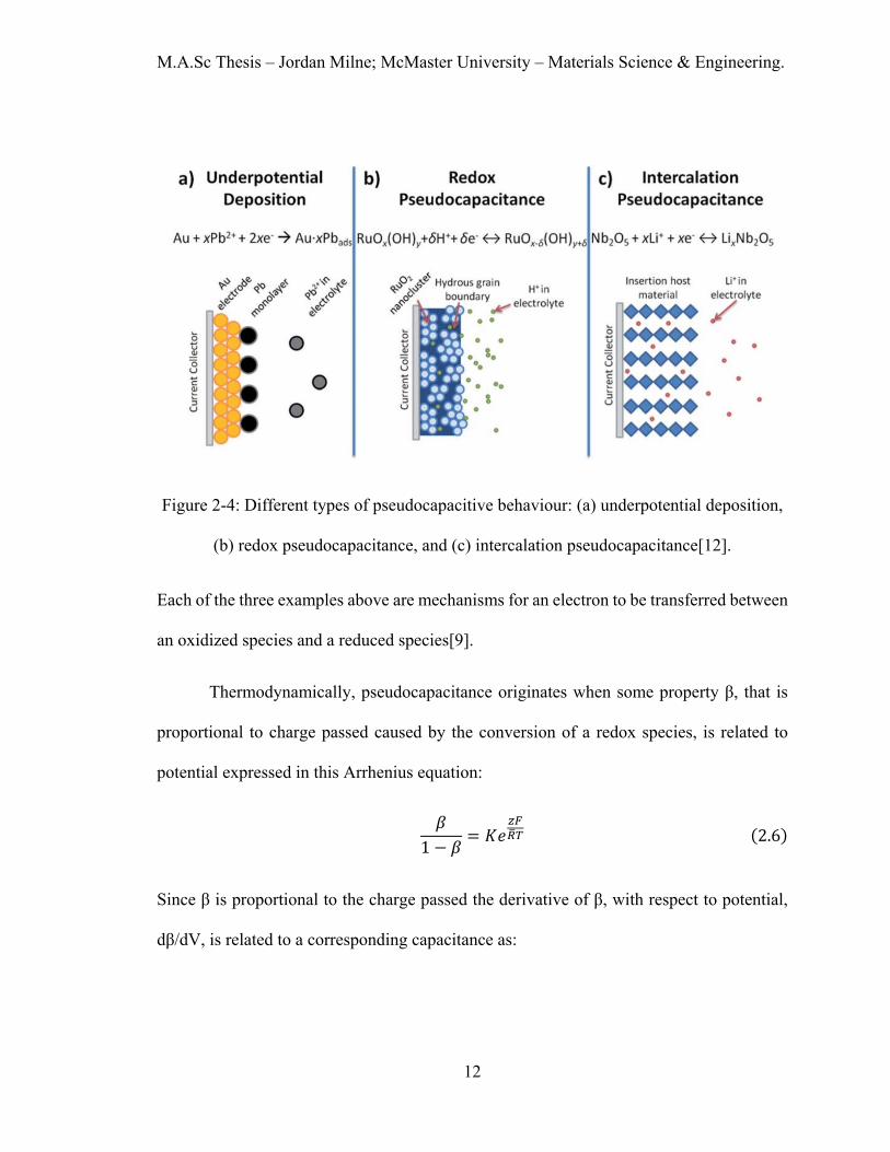
underpotential deposition and (3) intercalation pseudocapacitance[9]. These mechanisms
are displayed in Figure 2-4 [11]. Redox pseudocapacitance is a phenomenon that occurs
when electrolyte ions are adsorbed onto the surface resulting in Faradaic charge transfer
due to a redox reaction. Underpotential deposition arises when metal ions residing in the
electrolyte solution form a monolayer on a different metal's surface above their redox
potential. Intercalation pseudocapacitance is similar to that of Li-ion batteries and occurs
when ions migrate into layers or tunnels of an electrode material’s lattice resulting in a
highly reversible redox reaction without any crystallographic phase changes.
M.A.Sc Thesis – Jordan Milne; McMaster University – Materials Science & Engineering.
12
Figure 2-4: Different types of pseudocapacitive behaviour: (a) underpotential deposition,
(b) redox pseudocapacitance, and (c) intercalation pseudocapacitance[12].
Each of the three examples above are mechanisms for an electron to be transferred between
an oxidized species and a reduced species[9].
Thermodynamically, pseudocapacitance originates when some property β, that is
proportional to charge passed caused by the conversion of a redox species, is related to
potential expressed in this Arrhenius equation:
𝛽𝛽1 − 𝛽𝛽
= 𝐾𝐾𝑒𝑒𝑧𝑧𝑧𝑧𝐸𝐸�𝑇𝑇 (2.6)
Since β is proportional to the charge passed the derivative of β, with respect to potential,
dβ/dV, is related to a corresponding capacitance as:

M.A.Sc Thesis – Jordan Milne; McMaster University – Materials Science & Engineering.
13
𝑑𝑑𝛽𝛽𝑑𝑑𝑉𝑉
=𝐹𝐹𝑅𝑅𝑅𝑅
𝐾𝐾𝑒𝑒𝐾𝐾𝐾𝐾 �𝑧𝑧𝐹𝐹𝑅𝑅�𝑅𝑅�
�1 + 𝐾𝐾𝑒𝑒𝐾𝐾𝐾𝐾 �𝑧𝑧𝐹𝐹𝑅𝑅�𝑅𝑅��2 (2.7)
Conway continues to mention that this general equation above, Eq. 2.7, applies
equivalently to the 3 pseudocapacitance mechanisms, however with a closer look it is
realized that the Nernst equation is also suitable. For typical redox couple a simple redox
reaction can be written as well as the corresponding Nernst equation:
𝑂𝑂𝐾𝐾 + 𝑧𝑧𝑒𝑒− ↔ 𝑅𝑅𝑒𝑒𝑑𝑑 (2.8)
𝐸𝐸 = 𝐸𝐸0 + �𝑅𝑅�𝑅𝑅𝑧𝑧𝐹𝐹� ln
[𝑂𝑂𝐾𝐾][𝑅𝑅𝑒𝑒𝑑𝑑]
(2.9)
Now, equation Eq. 2.8 can be rewritten using Q as a given molar quantity of reagent, Q =
[Ox] + [Red]. If we rearrange Eq. 2.9 and write it in terms of [Ox] the result is:
�𝑂𝑂𝐾𝐾𝑄𝑄 �
1 − �𝑂𝑂𝐾𝐾𝑄𝑄 �= exp�
(𝐸𝐸 − 𝐸𝐸0)𝐹𝐹𝑅𝑅�𝑅𝑅
� = exp �∆𝐸𝐸 ∙ 𝐹𝐹𝑅𝑅�𝑅𝑅
� (2.10)
It is now more evident that the modified Nernst equation, Eq. 2.10, has the same structure
as Eq. 2.6 and can be used as a universal function for this type of system. Conway provides
an in-depth correlation of three types of systems that exhibit pseudocapacitance, which is
summarized in Table 2-1.

M.A.Sc Thesis – Jordan Milne; McMaster University – Materials Science & Engineering.
14
Table 2-1: Types of pseudocapacitive systems and their corresponding Nernst type
equations[9].
2.3 Electrode Materials for Supercapacitors
This subchapter will discuss different supercapacitor electrode materials for both
positive and negative electrodes in aqueous electrolytes. Qu et al.[13] completed a useful
chart (Figure 2-5) of common electrode materials and the most promising will be discussed
in the following sections.

M.A.Sc Thesis – Jordan Milne; McMaster University – Materials Science & Engineering.
15
Figure 2-5: The potential windows of a variety of pseudocapacitive materials in aqueous
electrolyte[13].
2.3.1 MnO2
Manganese dioxide (MnO2) is a promising positive electrode material as a result of
its high theoretical capacitance (1370 F g−1[12]), abundance, low cost, and environmentally
benign nature. An in-depth insight of the charge storage mechanism of MnO2 is of the
utmost importance in order to understand the parameters that effect the charge storage
process. MnO2 stores charge mainly through redox and intercalation pseudocapacitive
(Faradaic) reactions at the surface and subsurface of the material. MnO2 is

M.A.Sc Thesis – Jordan Milne; McMaster University – Materials Science & Engineering.
16
electrochemically active in the voltage window between 0 to 1.0 V (Vs. SCE) and exhibits
an ideal rectangular shape during cyclic voltammetry. The redox reaction[14] that occurs
in MnO2 can be written as:
𝑀𝑀𝑀𝑀(𝐼𝐼𝑉𝑉)𝑂𝑂2 + 𝐾𝐾𝐶𝐶+ + 𝑦𝑦𝐻𝐻+ + 𝐾𝐾𝑒𝑒− ↔ 𝑀𝑀𝑀𝑀(𝐼𝐼𝐼𝐼𝐼𝐼)(𝑥𝑥+𝑦𝑦),𝑀𝑀𝑀𝑀(𝐼𝐼𝑉𝑉)1−(𝑥𝑥+𝑦𝑦)𝑂𝑂2𝐶𝐶𝑥𝑥𝐻𝐻𝑦𝑦 (2.11)
Where C+ is Li+, Na+, K+, etc.
It is important to note that this reaction involves the incorporation of protons into
the MnO2 lattice which occurs reversibly and homogenously without any phase change[15].
This proton incorporation theory was solidified by Wen et al.[16] as their investigation
included a series of experiments that focused on the effect of protons as well as cation
species and respective concentrations. Wen et al. concluded that MnO2 capacitance
increases with increasing cation concentration up to a specific amount, albeit the difference
between different alkaline species (Li, K, Na) showed little variation. On top of this, it was
noted that the capacitance of MnO2 drastically decreased in aprotic solvents when
compared to water, rendering the effect of protons significant[16].
MnO2 can exist in a variety of different crystallographic forms such as: α-MnO2, β-
MnO2, γ-MnO2, δ-MnO2, λ-MnO2[17]. The α and γ phase include one-dimensional (1D)
tunnels in their structures whereas the δ phase is a 2D layered compound and the λ phase
possesses a 3D spinel structure, which are all shown in Figure 2-6. In the previous section
three types of pseudocapacitance were described: underpotential deposition, redox, and
intercalation. The crystal structure has a significant effect on the
intercalation/deintercalation of cations and in MnO2[18]. Brousse et al.[19] studied the

M.A.Sc Thesis – Jordan Milne; McMaster University – Materials Science & Engineering.
17
capacitance of different phases of MnO2. It was concluded that certain crystallographic
structures provided suitable gaps or tunnels to accommodate cations and protons which
resulted in high capacitance, such as δ-MnO2.
Figure 2-6: Crystal structures of α-, β-, γ-, δ-, and λ-MnO2[17].
2.3.2 Mn3O4
It is known that manganese oxides can experience phase transformations during
electrochemical cycling, resulting in an irreversible change in crystal structure causing a
change in electrochemical performance[20][21]. In a recent study by Agrawal et al.,

M.A.Sc Thesis – Jordan Milne; McMaster University – Materials Science & Engineering.
18
anelectrostatic spray deposition was used to synthesize a thin film electrode of
hausmannite-Mn3O4[22] . Agrawal reported a substantial increase in capacitance from 72
Fg−1 to 225 Fg−1 upon electrochemical cycling of the thin film Mn3O4 electrode, shown in
Figure 2-7. The change in resistance and capacitance was attributed to the electrochemical
phase transformation from the hausmannite-Mn3O4 to the more conducting birnessite-
MnO2, subsequently improving kinetics and conductivity[22]
Figure 2-7: Cycling behavior of the Mn3O4 electrode[22].
Another major benefit of the electrochemical transformation from hausmannite-
Mn3O4 to birnessite-MnO2 is the variety of synthesis procedures available for Mn3O4 that
are impractical for MnO2 synthesis, specifically, the use of capping agents. It is well known
that large agglomerated particles are detrimental to the performance of most energy storage
devices, so nanoparticles and nanostructures have gained immense research attention[23].
Zhao et al. used poly(acrylic acid) as a capping agent for Mn3O4 and achieved an average
M.A.Sc Thesis – Jordan Milne; McMaster University – Materials Science & Engineering.
19
particle size of 9.7 nm[24]. This highlights the weakness of the strong oxidizing precursor
KMnO4, that is practically unavoidable for synthesizing pseudocapacitive birnessite-MnO2.
KMnO4 reacts strongly with organics, rendering additives such as capping agents during
synthesis ineffective.
2.3.3 FeOOH
FeOOH is an iron oxyhydroxide that is used in many applications such as catalysts,
electrode materials, and magnetic recording media. FeOOH is low cost, environmentally
friendly, and offers pseudocapacitive behavior in aqueous electrolytes[25]. The charge
storage mechanism can be written as the following[26]:
𝐹𝐹𝑒𝑒𝑂𝑂𝑂𝑂𝐻𝐻 + 𝐻𝐻2𝑂𝑂 + 𝑒𝑒− ↔ 𝐹𝐹𝑒𝑒(𝑂𝑂𝐻𝐻)2 + 𝑂𝑂𝐻𝐻− (2.12)
The charge/discharge process involves the Fe3+/Fe2+ redox reaction in Eq. 2.12 resulting in
Faradaic charge storage. FeOOH is electrochemically active between -0.8 and 0 V (Vs.
SCE) which allows FeOOH electrodes to work in tandem as negative electrodes paired with
positive electrodes such as MnO2[27].
It has been reported that the amorphous phase provides superior supercapacitive
performance than that of its crystalline counterparts because the electrostatic forces during
charging and discharging can be easily released in the amorphous electrodes due to their
disordered structures[28]. A study by Li et al. demonstrated that amorphous phase Ni(OH)2
exhibited superior electrochemical performance because of its high structural disorder[29].
This finding has led to an increase in research of amorphous oxide/hydroxide electrode
material, specifically FeOOH. Until recently, FeOOH has been ignored as a potential

M.A.Sc Thesis – Jordan Milne; McMaster University – Materials Science & Engineering.
20
electrode material for supercapacitors because of its naturally high electrical resistance and
low cyclability. That being said, many studies have reported excellent cyclability, such as
Cheng et al., reporting 96% capacitance retention after 800 cycles[30] in high molar KOH
as the electrolyte. Although Cheng and other authors achieved excellent cyclic performance
with FeOOH they highlighted a new problem, which is many high performance positive
electrodes work best in neutral electrolytes[31], not highly basic or acidic electrolytes. It is
crucial that both positive and negative electrodes exhibit good electrochemical performance
in the same electrolyte.
2.3.4 Other Metal Oxides
Other noteworthy metal oxide materials are RuO2, Co3O4, NiO/Ni(OH)2, and V2O5.
RuO2 has been studied as a positive electrode for supercapacitors for many years and has
outstanding pseudocapacitive performance in both crystalline and amorphous phases[32].
One major benefit RuO2 has over most other oxides is it has potentially three redox couples
corresponding to four stable redox states, Ru2+/Ru3+, Ru3+/Ru4+ and Ru4+/Ru6+[33]. The
charge storage mechanism of RuO2 involves proton intercalation in acidic and alkaline
electrolytes as shown in the following equation[34].
𝑅𝑅𝑅𝑅𝑂𝑂2 + 𝐾𝐾𝐻𝐻+ + 𝐾𝐾𝑒𝑒− ↔ 𝑅𝑅𝑅𝑅𝑂𝑂𝐻𝐻𝑥𝑥 (2.13)
A hydrated RuO2·xH2O amorphous compound was found to have a specific capacitance of
768 F g-1[35]. While RuO2 has exceptional electrochemical performance, the cost of RuO2
is a major barrier for the commercialization of this material[36].

M.A.Sc Thesis – Jordan Milne; McMaster University – Materials Science & Engineering.
21
Another interesting positive electrode material that has gained research attention is
Co3O4 due to its redox pseudocapacitance, impressive reversibility, and extremely high
theoretical specific capacitance of 3580 F g-1[37]. The charge storage mechanism for cobalt
oxide is from the redox reactions of Co2+/Co3+ which is[38]:
𝐶𝐶𝑜𝑜3𝑂𝑂4 + 𝑂𝑂𝐻𝐻− + 𝐻𝐻2𝑂𝑂 ↔ 3𝐶𝐶𝑜𝑜𝑂𝑂𝑂𝑂𝐻𝐻 + 𝑒𝑒− (2.14)
𝐶𝐶𝑜𝑜𝑂𝑂𝑂𝑂𝐻𝐻 + 𝑂𝑂𝐻𝐻− ↔ 𝐶𝐶𝑜𝑜𝑂𝑂2 + 𝐻𝐻2𝑂𝑂 + 𝑒𝑒− (2.15)
Xiang et al. synthesized Co3O4/reduced graphene oxide (rGO) composite through
hydrothermal methods[39]. The authors reported a high specific capacitance of 472 F g-1
and 96% retention after 1000 cycles. An even more impressive result was then reported by
Kumar et al. who synthesized graphene wrapped cobalt oxide via microwave irradiation
forming a robust device with an impressive specific capacitance of 712 F g-1[40]. Although
Co3O4 has very high stability and capacitance values, it is limited not only by its high price,
but also its high toxicity.
Nickel oxides and hydroxides are other well researched positive supercapacitor
electrode materials. Nickel-based electrode materials are becoming more common in
energy storage devices, specifically in supercapacitor research due to their higher
theoretical capacitance, charge density, and chemical stability[41]. NiO and Ni(OH)2 have
similar charge/discharge mechanisms as FeOOH as they involve redox reactions with
hydroxide groups as shown respectively[42], [43]:
𝑁𝑁𝑁𝑁𝑂𝑂 + 𝑧𝑧𝑂𝑂𝐻𝐻− ↔ 𝑧𝑧𝑁𝑁𝑁𝑁𝑂𝑂𝑂𝑂𝐻𝐻 + (1 − 𝑧𝑧)𝑁𝑁𝑁𝑁𝑂𝑂 + 𝑧𝑧𝑒𝑒− (2.16)

M.A.Sc Thesis – Jordan Milne; McMaster University – Materials Science & Engineering.
22
𝛼𝛼 − 𝑁𝑁𝑁𝑁(𝑂𝑂𝐻𝐻)2 + 𝑂𝑂𝐻𝐻− ↔ 𝛾𝛾 − 𝑁𝑁𝑁𝑁𝑂𝑂𝑂𝑂𝐻𝐻 + 𝐻𝐻2𝑂𝑂 + 𝑒𝑒− (2.17)
NiO has been synthesized in a plethora of ways including: heat treatment of
electrodeposited nickel oxides/hydroxides[44], sol-gels[45], and precipitation[46]. Dar et
al. used a thermally treated electrodeposition method to synthesize a thin film electrode
resulting in the highest recorded specific capacitance for NiO of 2093 F g-1[47]. Chai et al.
used a chemical precipitation and ultrasonication with rGO to synthesize a Ni(OH)2-rGO
composite electrode which attained an impressive specific capacitance of 2053 F g-1[43].
Another material of particular interest is V2O5, due to the structure of its valence
electron layer, which can be written as 3d34s2. This electron configuration has five valence
electrons which can participate in bonding and provide impressive pseudocapacitance[48].
These multiple valence states give an unusually large potential window range seen in Figure
2-5. In addition to the large potential window, V2O5 is low cost, abundant, and has high
theoretical pseudocapacitance (2120 F g-1)[49]. Pan et al. took advantage of the quasi-
metallic phase of vanadium oxide, V2O3, which has a resistance lower than that of V2O5 by
over 6 orders of magnitude shown in Figure 2-8[50].

M.A.Sc Thesis – Jordan Milne; McMaster University – Materials Science & Engineering.
23
Figure 2-8: Representative resistivity of V2O5, VO2, and V2O3[50].
Pan et al. fabricated V2O3/V2O5 core-shell nanostructures by synthesizing V2O3
particles in which the surface of these particles naturally oxidizes to a more stable 4+ or 5+
state, which also happens to have superior pseudocapacitive properties. V2O5 stores charge
through pseudocapacitive redox reactions as well as intercalation which can be written
as[51]:
𝑉𝑉2𝑂𝑂5 + 𝐾𝐾𝐶𝐶+ + 𝐾𝐾𝑒𝑒− ↔ 𝑉𝑉2𝑂𝑂5𝐶𝐶𝑥𝑥 (2.18)
A remarkably high specific capacitance of 2590 F g-1 was reported by Shakir et al.
in thin films deposited using a layer-by-layer technique. One layer consisted of multi-
walled carbon nanotubes (MWCNT) with an ultra thin film (3 nm) of V2O5 grown on them
while a graphene layer was alternatively inserted[52].

M.A.Sc Thesis – Jordan Milne; McMaster University – Materials Science & Engineering.
24
2.3.5 Carbon Materials
A variety of carbon-based materials ranging from carbon nanotubes (CNT) to
activated carbon (AC) are the most widely used EDLC electrodes and are common among
other types of supercapacitors as well[53]. On top of being the sixth most abundant element
in the earth’s crust, most carbonaceous materials are highly conductive and can achieve
enormously high specific surface area[54]. Carbon-based supercapacitors can store
impressive amounts of energy through the utilization of the large surface area (A),
combined with the atomic range of charge separation distances (d), explained in Eq.
2.1[55]. Carbon electrodes offer high power density, excellent cycle life, and excellent
dependability[56]. However, their main drawbacks are low energy density and high self
discharge[57].
Over the last decade, graphene and reduced graphene oxide have been heavily
researched and show promising potential for supercapacitor applications. Graphene is a
two-dimensional structure (one carbon atom in thickness) that is remarkably conductive as
well as chemically stable, resulting in excellent energy storage capability[58]. rGO has the
ability to introduce surface functional groups including alcohols, epoxides, carbonyls and
carboxylic acids which can act as redox sites and contribute to pseudocapacitance[59]. A
study by Wu et al. displayed a synergistic performance improvement when coupling rGO
with RuO2. Wu anchored RuO2 nanoparticles on rGO surface via a precipitation method.
Wu reported superior capacitance from the RuO2–rGO composite compared to the results
of pure rGO or pure RuO2. The authors concluded that the rGO sheets aided in separating

M.A.Sc Thesis – Jordan Milne; McMaster University – Materials Science & Engineering.
25
in separating the RuO2 nanoparticles, avoiding the agglomeration of the RuO2 nanoparticles
while simultaneously providing a conductive pathway[60].
2.3.6 Conductive additives
A common factor in the aforementioned electrode materials is conducting additives.
Homogenous electrode materials give inadequate performance due to their intrinsically
weaker material properties such as conductivity, cyclic and mechanical stability, unless
expensive and/or unscalable nanosynthesis techniques are used[61]. Most metal oxides are
electrically resistive by nature[62], increasing both sheet resistance and charge transfer
resistance causing a notable IR loss at higher current densities. The rapidly evolving field
of nanotechnology has provided an impetus for advancements in supercapacitor electrode
materials. A variety of carbon materials such as activated carbon[63], graphene[64],
reduced graphene[65], and carbon nanotubes[66] are used in composite metal oxide
electrodes to enhance conductivity and mechanical strength. Zhao et al. synthesized
nanostructured graphene/NiO material for high performance composite supercapacitor
electrodes[67]. As shown in Figure 2-9, Zhao increased the capacitance of pure NiO by
172% by adding a graphene matrix improving the conductivity of the composite.

M.A.Sc Thesis – Jordan Milne; McMaster University – Materials Science & Engineering.
26
Figure 2-9: Specific capacitance over 1000 cycles of pure NiO and graphene/NiO[67].
MWCNT is another conducting material used to mitigate the conductivity problem
that persists in most metal oxides owing to MWCNT’s large surface area, superior
conductivity and intertwined mesoporous structure[68]. Xia et al. investigated
hydrothermally synthesized MnO2 deposited onto MWCNT which resulted in a specific
capacitance of 310 F g-1 and improved rate capability which significantly exceeds that of
pure MnO2 or pure MWCNT. The improved rate capability and capacitance of the
MnO2/MWCNT composite electrode over that of the pure MnO2 electrode is due to the
lower charge transfer resistance and diffusion related resistance reported in Xia’s
electrochemical impedance spectroscopy (EIS) analysis. Xia et al. concluded that the 3D
electron path network provided by the MWCNT facilitate faster electron transport and
mechanical stability.

M.A.Sc Thesis – Jordan Milne; McMaster University – Materials Science & Engineering.
27
2.4 Asymmetric Supercapacitors
In order to fully appreciate the potential of asymmetric supercapacitors, an
understanding of electrolyte selection is necessary. Firstly, electrolytes used in
supercapacitor applications should ideally be inexpensive and have: stability over a wide
potential range, high ionic conductivity, low toxicity, as well as a small solvated ionic
radius [69]. The most important property of the electrolyte is its stability over a potential
range since the energy storage in supercapacitors is proportional to the square of applied
voltage (Eq. 2.3). It is well known that the thermodynamic potential window of water is
1.23 V, restricting the use of aqueous electrolytes for commercialized “symmetric”
supercapacitor technology (two identical carbon electrodes). For this reason, organic
electrolytes have been commercially used for EDLC type devices as organic electrolytes
are stable above 2.5 V[70].
Moreover, an asymmetric supercapacitor is a device that consists of two dissimilar
electrodes that are electrochemically active in different potential windows[71]. Until
recently, asymmetric supercapacitors were not well researched, as seen in Figure 2-10.

M.A.Sc Thesis – Jordan Milne; McMaster University – Materials Science & Engineering.
28
Figure 2-10: Asymmetric supercapacitor publications since 2006[71].
The driving force of this exponential increase in research of asymmetric supercapacitors is
due to the high energy density achieved by pseudocapacitors in various potential ranges.
The potential windows of the positive and the negative electrodes are limited by the oxygen
and the hydrogen evolution reactions in aqueous electrolytes. Careful selection of positive
and negative electrodes with high overpotentials allow aqueous-based asymmetric
supercapacitors to achieve a voltage up to 2 V, eliminating the main advantage organic
electrolytes hold.[72]. Other advantages of using aqueous electrolytes are they have low
ESR, are cost-effective, and eco-friendly[73].
Unfortunately, a major roadblock for the development of asymmetric
supercapacitors is the inferior capacitances of negative electrode materials, displayed in

M.A.Sc Thesis – Jordan Milne; McMaster University – Materials Science & Engineering.
29
Figure 2-11. The low capacitance of the negative electrode leads to low capacitance of the
cell (Ccell) according to the fundamental equation, where C+ and C- are specific capacitances
of positive and negative electrodes respectively[69]:
1𝐶𝐶𝑐𝑐𝑐𝑐𝑑𝑑𝑑𝑑
=1𝐶𝐶+
+1𝐶𝐶−
(2.19)
It is clear that in order to fabricate practical asymmetric supercapacitors improved negative
electrode materials are necessary.
Figure 2-11: Specific capacitance of selected anode and cathode materials[69].

M.A.Sc Thesis – Jordan Milne; McMaster University – Materials Science & Engineering.
30
2.5 Mass Loading
Although the specific capacitances reported in the previous subchapters are
impressive, there is a fundamental problem that must be addressed. Supercapacitor
electrodes and devices reporting exceptional electrochemical performances typically have
a mass loading of active material (pseudocapacitive material) less than 0.2 mg cm2[74].
Since pseudocapacitive reactions occur mostly at the surface, electrolyte ions have easy
access and short diffusion distance to active material of thin film (low mass loading)
electrodes. For this reason, low mass loading electrodes have high specific capacitance and
rate capability results. More importantly, low mass loading electrodes have low areal
capacitance and low areal energy and power densities restricting their practicality in
supercapacitors for energy storage applications[75]. In addition, an important characteristic
of supercapacitor electrodes is the ratio (Rm) of active mass to the mass of the current
collector[76]. Many thin film electrodes have micrograms of active material on heavy
metallic current collectors.
𝑅𝑅𝑚𝑚 =𝑚𝑚𝑚𝑚𝑚𝑚𝑚𝑚 𝑜𝑜𝑜𝑜 𝑚𝑚𝑎𝑎𝑎𝑎𝑁𝑁𝑎𝑎𝑒𝑒 𝑚𝑚𝑚𝑚𝑎𝑎𝑒𝑒𝑚𝑚𝑁𝑁𝑚𝑚𝑚𝑚𝑚𝑚𝑚𝑚𝑚𝑚𝑚𝑚 𝑜𝑜𝑜𝑜 𝑎𝑎𝑅𝑅𝑚𝑚𝑚𝑚𝑒𝑒𝑀𝑀𝑎𝑎 𝑎𝑎𝑜𝑜𝑚𝑚𝑚𝑚𝑒𝑒𝑎𝑎𝑎𝑎𝑜𝑜𝑚𝑚
(2.20)
Rm values for thin film electrodes are typically below 1–2%, but for practical
applications this percentage must be much higher[77].
2.6 Fabrication Methods
A major challenge in supercapacitor electrode fabrication is to achieve high
capacitance, capacitance retention at high charge-discharge rates, and adequate cycle life

M.A.Sc Thesis – Jordan Milne; McMaster University – Materials Science & Engineering.
31
for electrodes with high active mass loadings[78]. In order to synthesize high performing
practical supercapacitor electrodes with high mass loadings, innovative fabrication
methods must be utilized to synthesize composite electrode materials. These fabrication
methods will be discussed in the following subchapters.
2.6.1 Electrophoretic Deposition
An electrode fabrication technique that is used for a variety of electrode materials
is electrophoretic deposition (EPD). This method uses an electric field which moves
charged particles towards an electrode serving as the deposition surface[79]. EPD is an
established, economical, and scalable process that has been successfully used for the
deposition of activated carbon, CNT, graphene, and transition metal oxides. EPD has
numerous advantages for the fabrication of films from charged colloidal suspensions,
including controllable thickness, high deposition rates, uniformity, and simplicity in terms
of equipment[80].
A major catalyst for the increased use of electrophoretic deposition for
supercapacitor electrodes stems from the power density equation Eq. 2.4, where
minimizing the ESR increases the power density. Du et al. used EPD to deposit MWCNT
which resulted in a uniform deposition that was efficiently bonded to the current
collector[81]. This produced a direct conductive path from MWCNT film to the current
collector, reducing contact and internal resistance of the electrode. An interesting study by
An et al. reported a simple, high yield, large surface area, inexpensive, and environmentally
benign fabrication of films comprised of rGO platelets using EPD shown in Figure 2-

M.A.Sc Thesis – Jordan Milne; McMaster University – Materials Science & Engineering.
32
21[82]. The oxygen functional groups of rGO were substantially removed by the EPD
process, and the deposited film displayed improved electrical conductivity compared to
rGO papers made by the filtration method[83].
Figure 2-12: Schematic diagram of the simple EPD process[82].
In addition to homogenous films, nanocomposite films can also be deposited using
EPD. In an article by Wang et al., charging additives were added to the EPD solution
adsorbing onto both MnO2 and MWCNT causing both species to become charged[84]. The
nanocomposite films were studied in supercapacitor applications and resulted in a high
specific capacitance of 553 Fg−1.

M.A.Sc Thesis – Jordan Milne; McMaster University – Materials Science & Engineering.
33
2.6.2 Chemical Bath Deposition
Similar to EPD, chemical bath deposition (CBD) is a low temperature, simple, and
inexpensive synthesis method[85]. Thin films are formed in CBD when the solution is
saturated. To clarify, the ionic product of anions and cations in the synthesis solution is
equal to the solubility product of the metallic precursors and when the latter is surpassed,
ions combine and precipitation occurs on the substrate[86]. A notable advantage of CBD is
that electrical conductivity is not a requirement for the substrate, in fact, any insoluble
material to which the synthesis solution has ionic access to is an appropriate substrate[87].
An example of CBD reactions to form nickel-cobalt sulfide supercapacitor
electrodes can be seen in a detailed report by Zhao et al.[88]. Firstly, Zhao dissolved nickel
and cobalt salts with hexamethylenetetramine in a mix of deionized water and ethanol, as
seen in Eq.2.21.
Zhao et al. then reacted the nickel-cobalt-hydroxide product with a certain amount of
thioacetamide which acted as the sulfur supply shown in Eq. 2.22, which produced the final
electrode material NiCoxSy.
𝑁𝑁𝑁𝑁2+ + 2𝐾𝐾𝐶𝐶𝑜𝑜2+ + 3 𝐶𝐶𝑂𝑂2 + 12𝑂𝑂𝐻𝐻− → 2𝑁𝑁𝑁𝑁𝐶𝐶𝑜𝑜𝑥𝑥(𝐶𝐶𝑂𝑂3)1.5(𝑂𝑂𝐻𝐻)3 + 3𝐻𝐻2𝑂𝑂 (2.21)
2𝑁𝑁𝑁𝑁𝐶𝐶𝑜𝑜𝑥𝑥(𝐶𝐶𝑂𝑂3)1.5(𝑂𝑂𝐻𝐻)3 + 2𝑦𝑦𝐻𝐻2𝑆𝑆 + (𝑦𝑦 − 3)𝑂𝑂2 → 2𝑁𝑁𝑁𝑁𝐶𝐶𝑜𝑜𝑥𝑥𝑆𝑆𝑦𝑦 + (3 + 2𝑦𝑦)𝐻𝐻2𝑂𝑂 + 3𝐶𝐶𝑂𝑂2 (2.22)
This CBD synthesis procedure produced a thin film flaky nickel cobalt sulfide electrode
which had a specific capacitance of 1196 F g-1.

M.A.Sc Thesis – Jordan Milne; McMaster University – Materials Science & Engineering.
34
The freedom in substrate material selection given by CBD allowed for layered
birnessite-MnO2 films to be deposited on flexible transparent plastic substrates[89].
Compressive and tensile bending tests displayed that the MnO2 film electrodes retain
exceptional electrochemical stability as well as mechanical flexibility. In addition to metal
oxides, CBD can also be used to synthesize conducting polymer electrodes. Polyaniline
(PANI) is a conductive polymer that exhibits pseudocapacitive behavior[90]. In an
impressive study by Deshmukh et al., PANI thin films were synthesized by chemical
oxidization of the monomer aniline with ammonium persulfate in a sulfuric acid
solution[91]. One disadvantage of CBD is the reaction-based deposition can be time
consuming, hindering its practicality. A technique used by Deshmukh et al. was to use
microwaves to enhance the CBD process. This technique reduced synthesis time
significantly producing a high-performing PANI electrode with a specific capacitance of
753 F g-1. A key advantage of CBD is that composite electrodes can be synthesized with
desirable morphologies and low ESR. For example, Qui et al. synthesized graphene-NiO
core-shell nanosheets through a simple CBD method. The interconnections among the
nanosheets exhibited excellent electrical conductivity and a high energy density of 19.5 Wh
kg-1.
2.6.3 Heterocoagulation
As mentioned previously, thin film electrodes are not practical for supercapacitor
electrodes for energy storage applications. To maintain low internal resistance of the
electrode conductive additives are necessary. Heterocoagulation is a recent innovative

M.A.Sc Thesis – Jordan Milne; McMaster University – Materials Science & Engineering.
35
fabrication route used to link CNT to pseudocapacitive materials. This method uses a
dispersing agent for the dispersion of oxide nanoparticles and an oppositely charged
dispersing agent for the dispersion of CNT forming a composite with low internal
resistance, as shown in Figure 2-13[92].
Figure 2-13: Synthesis process for heterocoagulation using MWCNT and MnO2[92].
From the previous studies, it has been made clear that covalent functionalization
methods for the dispersion of CNT are not ideal due to the degradation of MWCNT
structure and properties from such techniques[93]. In a heterocoagulation method used by
Ata et al., the surface of MWCNT was modified using small charged aromatic molecules
adsorbed on the surface with π-π staking and hydrophobic interactions, improving the
MWCNT dispersion[94]. Ata selected Mn3O4 as the active material for the electrode which
was dispersed using a molecule called P(SSA-MA). This unique multifunctional molecule
allowed efficient adsorption on Mn3O4 imparted by the MA monomer, whereas SSA

M.A.Sc Thesis – Jordan Milne; McMaster University – Materials Science & Engineering.
36
monomers provided a negative charge. Enhanced dispersion of the individual electrode
components and their electrostatic heterocoagulation facilitated improved mixing of these
components, producing a well mixed composite electrode with high active mass loading.
2.6.4 Particle Extraction Through the Liquid-Liquid Interface
The Liquid-liquid interface (LLI) provides a unique two-dimensional environment
different from that of a bulk fluid. Novel methods of particle synthesis and surface
functionalization of material at the LLI have combined the advantages of material synthesis
in organic and aqueous phases[95]. In particle extraction through the liquid-liquid interface
(PELLI), inorganic particles are synthesized in an aqueous solution and transferred to an
immiscible organic solvent as seen in Figure 2-14[96].
Figure 2-14: Schematic of (a) precipitation of particles in aqueous solution, (b,c) different
stages in extraction[96].
PELLI addresses a major difficulty for the synthesis of nanoparticles by wet
chemical methods, which is the agglomeration of nanoparticles after removal from the
solution after synthesis. Hydroxide groups on the particle surface can undergo
condensation, forming oxo-bridges which results in the agglomeration of oxide and

M.A.Sc Thesis – Jordan Milne; McMaster University – Materials Science & Engineering.
37
hydroxide particles while drying. In many applications, co-dispersion of non-agglomerated
nanoparticles with other materials is necessary[97]. Specifically, in supercapacitor
electrode fabrication, active material must be combined with conductive additives and
water insoluble polymer binders[98]. To clarify, PELLI is used to co-disperse active
materials prepared in aqueous solutions by transferring the particles to an immiscible
organic solvent by using multifunctional extractor molecules. These extracted particles are
then mixed with conductive additives avoiding the agglomeration that occurs during the
drying stage. The extractor molecules typically consist of a hydrophobic carbon chain as
well as a functional group that facilitates adsorption to the active material.
In a study by Chen et al., multiple distinct molecules were used to transfer MnO2
particles from the aqueous synthesis solution and disperse them in an organic phase[99]. In
the PELLI fabrication technique the agglomeration of oxide particles during drying was
avoided and improved mixing of MnO2 and MWCNT occurred in the organic phase. The
reduction in agglomeration using PELLI facilitated mixing of components resulting in
significantly lower resistance shown in Figure 2-15. Not only was the ESR reduced using
PELLI but the capacitance of the electrode using the most suitable extractor molecule
doubled the capacitance of the electrode synthesized without PELLI.

M.A.Sc Thesis – Jordan Milne; McMaster University – Materials Science & Engineering.
38
Figure 2-15: Nyquist plot of complex impedance for MnO2-MWCNT electrodes
prepared (a) without extraction and (b–d) by PELLI using (b) 16-phosphonohexadecanoic
acid, (c) octadecylphosphonic acid, and (d) stearic acid extractors[99].

M.A.Sc Thesis – Jordan Milne; McMaster University – Materials Science & Engineering.
39
Chapter 3: Problem Statements and Objectives
To meet the ever-increasing energy storage requirements, supercapacitors with high
active mass loadings are necessary to achieve high energy and power densities. High mass
electrodes suffer from particle agglomeration causing poor electrolyte access to active
material. On top of this, the agglomeration of active material such as oxides and hydroxides
cause poor mixing with conductive additives, reducing the overall electrochemical
performance of the device. Furthermore, the lack of research in the area of negative
electrodes for supercapacitor devices has caused the improvements in negative electrode
performance to lag behind that of positive electrodes.
One objective of this investigation is to fabricate high mass electrodes with good
electrochemical performance and rate capability. To achieve this, the development a novel
processing technique for the synthesis of non-agglomerated particles is necessary. A second
objective of this investigation is to develop an advanced negative electrode for the
fabrication of asymmetric supercapacitors

M.A.Sc Thesis – Jordan Milne; McMaster University – Materials Science & Engineering.
40
Chapter 4: Experimental Procedures
4.1 Chemicals and Materials
Table 4-1: Table of materials used.
Material Use Material Name Source
Active Materials
Potassium permanganate (KMnO4) Sigma-Aldrich Iron chloride hexahydrate (FeCl3·6H2O) Sigma-Aldrich
Manganese nitrate tetrahydrate (Mn(NO)3·4H2O) Sigma-Aldrich
Dopant Zinc chloride (ZnCl2) Anachemia
Extracting Agents Octyl gallate (OG) Sigma-Aldrich Octanohydroxamic acid (OHA) TCI Chemicals Bufexamac (BF) TCI Chemicals
Organic Solvents Ethanol Commercial Alcohols n-butanol Fisher Chemical
Conductive Additive Multi-walled carbon nanotubes (MWCNT) (ID: 4 nm, OD: 13 nm, Length: 1-2 µm)
Bayer
Binder Poly(vinyl butyral-co-vinyl alcohol-co-vinyl acetate, Average Mw = 50000- 80000 (PVB)
Sigma-Aldrich
Dispersing Agent Methyl Violet 3RAX Sigma-Aldrich Calconcarboxylic acid (CA) Sigma-Aldrich
Electrolyte Sodium sulfate (Na2SO4) Caledon Laboratory Chemicals
Current Collector Nickel foam Vale Reference Electrode Potassium chloride (KCl) Fisher Chemical
Base (pH Adjustment) Sodium Hydroxide (NaOH) Caledon Laboratory Chemicals
4.2 Synthesis of Electrode Materials Using Octyl Gallate for PELLI
A simple multiple-step procedure was performed to obtain the oxide nanoparticles
extracted by the liquid-liquid extraction method using Octyl Gallate (OG). For the α-
FeOOH: (i) 330 mg of FeCl3∙6H2O was dissolved in 50 mL of deionized (DI) H2O using

M.A.Sc Thesis – Jordan Milne; McMaster University – Materials Science & Engineering.
41
mild stirring. (ii) 1M NaOH was added to the solution until pH 7 was reached under
continuous stirring. (iii) A new solution with 33 mg of OG was dissolved in 20 mL of n-
butanol using ultrasonic bath. (iv) Both solutions were mixed under stirring for 2 min and
set to rest for 2 min for phase transfer to occur. (v) The solution was poured into a separation
funnel and the bottom aqueous phase was removed. (vi) The remaining nanoparticles in the
n-butanol phase were mixed using ultrasonic bath with a fresh solution containing 25 mg
of MWCNT already dispersed with 25 mg of calconcarboxylic acid in 20 mL of n-butanol.
(vii) The final solution was washed with 750 mL of water followed by 250 mL of ethanol
under vacuum pump-filtration then stored in a desiccator.
For the Mn3O4: (i) 330 mg of Mn(NO3)2·4H2O was dissolved in 50 mL of H2O
using ultrasonic bath. (ii) 2M NaOH solution was added dropwise under ultrasonic bath
until a pH of 10 was achieved. The steps from (iii) to (vii) were the same previously
described.
For the MnO2: (i) 180 mg of KMnO4 was dissolved in a solution containing 100
mL of H2O and 20 mL of n-butanol by stirring overnight. (ii) 25 mg of OG was dissolved
in 20 mL of n-butanol using ultrasonic bath. The subsequent steps are described above as
(iv) to (vii).
ZnO was prepared by chemical precipitation from 0.26 M Zn(NO3)2 solutions (100
mL) in water at a temperature of 70 °C and pH of 8. The pH of the solutions was adjusted
using 1 M NaOH.

M.A.Sc Thesis – Jordan Milne; McMaster University – Materials Science & Engineering.
42
4.3 Synthesis of Electrode Materials Using Octanohydroxamic Acid for
PELLI
For the Mn3O4: (i) 330 mg of Mn(NO3)2·4H2O was dissolved in 50 mL of H2O
using an ultrasonic bath. (ii) 33 mg of OHA was dissolved in 2M NaOH solution which
was then added dropwise into the dissolved Mn(NO3)2 solution under ultrasonic bath until
pH 10 was reached. (iii) 20 mL of pure n-butanol was added to the solution. (iv) The
solution was mixed under stirring for 2 min and set to rest for 2 min for phase transfer to
occur. (v) The solution was poured into a separation funnel and the bottom aqueous phase
was removed. (vi) The remaining nanoparticles in the n-butanol phase were mixed using
an ultrasonic bath in a fresh solution containing 25 mg of MWCNTs already dispersed in
20 mL of n-butanol with 25 mg of OHA. (vii) The final solution was washed with 750 mL
of water followed by 250 mL of ethanol under vacuum pump-filtration then stored in a
desiccator.
For the MnO2: (i) 180 mg of KMnO4 was dissolved in a solution containing 100
mL of H2O and 20 mL of n-butanol by stirring overnight. (ii) 33 mg of OHA was dissolved
in 20 mL of n-butanol using an ultrasonic bath. (iv) Both solutions were mixed under
stirring for 2 min and set to rest for 2 min for phase transfer to occur. The steps from (v) to
(vii) were the same as previously described.
4.4 Synthesis of Zn/FeOOH Electrode Materials
For the Zn/FeOOH: (i) 330 mg of FeCl3∙6H2O and 30 mg of ZnCl2 was dissolved
in 12.5 mL of H2O using mild stirring. (ii) 4M NaOH was added to the solution until pH

M.A.Sc Thesis – Jordan Milne; McMaster University – Materials Science & Engineering.
43
13 was reached under continuous stirring. (iii) The freshy precipitated Zn doped FeOOH
particles were filtered with DI water until pH returned to 7. (iv) The particles were re-
dispersed in DI water and mixed with a solution containing 23 mg of MWCNT already
dispersed in 75 mL of DI water with 23 mg of Methylene Violet 3RAX as a dispersant.
(vii) The solution of Zn/FeOOH and MWCNT was ultrasonicated for 100 min. (viii) The
final solution was washed with 750 mL of water followed by 250 mL of ethanol using
vacuum pump-filtration then stored in a desiccator.
The Pure FeOOH electrode was prepared in an identical manner excluding the
30mg of ZnCl2 in step (i) and only a pH of 7 was reached in step (ii).
4.5 Characterization of Electrode Materials
4.5.1 SEM
The microstructures of the composite electrodes were qualitatively analyzed using
scanning electron microscopy (SEM) at the Canadian Centre for Electron Microscopy using
a JEOL JSM-7000F. The beam current was set to the auto-low or auto-medium setting for
the instrument depending on the sample. Electrodes were prepared for SEM analysis by
adhering a small cut-off of the electrode on the centre of a piece of double-sided copper
tape on a stainless-steel sample stub. Silver or nickel paste was applied along the edges of
the copper tape to improve conductivity to the stub. Due to the conductivity needed for
enhanced SEM images the samples were coated with a 5 nm layer of platinum.

M.A.Sc Thesis – Jordan Milne; McMaster University – Materials Science & Engineering.
44
4.5.2 FTIR and XPS
Fourier transform infrared spectroscopy (FTIR) was performed at the McMaster
Biointerfaces Institute- to obtain an infrared spectrum of absorption from dispersing agents
used in the PELLI experiments. The instrument used was a Bio-Rad FTS-40. X-ray
photoelectron spectroscopy (XPS) was used to study the difference in oxidation states of
Mn3O4 before and after cycling procedures. The instrument used was a Physical Electronics
Quantera II.
4.5.3 XRD
2D diffraction data was collected at the MAX Diffraction Facility at McMaster
University, Hamilton, ON.
For iron-containing samples X-Ray diffraction (XRD) testing was performed using
the Bruker D8 DISCOVER with DAVINCI.DESIGN diffractometer, equipped with Cobalt
Sealed Tube Source (λ avg = 1.79026 Å), Vantec 500 (MiKroGap TM technology) area
detector. 5 frames were captured with an exposure time of 420 seconds per frame with a
power setting of 35 kV, 45 mA.
For manganese containing samples instrumentation with Bruker Smart6000 CCD
area detector and a Rigaku RU200 Cu Kα̅ rotating anode was used. 7 frames were used
with 300 seconds per frame and a power setting of 50 kV, 90 mA.
2D frames were collected with DIFFRAC-Measurement Centre version 4.2 software
and integrated to 1D using DIFFRAC.EVA Version 4.0. Phase identification was
performed using the integrated ICDD PDF-4 + 2018 powder database in DIFFRAC.EVA.

M.A.Sc Thesis – Jordan Milne; McMaster University – Materials Science & Engineering.
45
4.6 Fabrication of Electrodes
The supercapacitor electrodes were synthesised via slurry impregnation. To begin,
a piece of 95% porosity nickel foam was cut into 1.5 cm by 1cm rectangular pieces and
cleaned using DI water and ethanol. The mass of the nickel foam was obtained using a
Toledo AX105 scale prior to impregnation. The composite electrode material previously
synthesized was ground in a mortar with 3 wt% of binder (PVB) dissolved in ethanol. The
desired mass loading was then loaded onto a 1 cm by 1cm section of the nickel foam. The
impregnated nickel foam was dried and then placed on the scale to determine if more mass
loading was necessary. Once the nickel foam was loaded with the desired mass it was rolled
in three steps to around 30% of the original thickness resulting in an electrode
approximately 0.37 mm thick. After rolling, the mass of the electrode was measured again
and the difference from the unimpregnated nickel foam was the mass loading of the
electrode. Copper wire was soldered to the unimpregnated area of the nickel foam and
wired through a glass tube. The glass tube, soldered copper joint, and exposed nickel foam
were sealed using LePage Speed Set Epoxy.
4.7 Electrochemical Characterization of Electrodes
To get an in-depth analysis of multiple aspects of the electrodes, various
electrochemical characterization techniques were used. Single electrodes were tested using
a three-electrode setup with the counter electrode as platinum gauze and the reference as a

M.A.Sc Thesis – Jordan Milne; McMaster University – Materials Science & Engineering.
46
saturated calomel electrode (SCE). All tests were performed in 0.5 M Na2SO4 aqueous
electrolyte at room temperature.
4.7.1 Cyclic Voltammetry
Cyclic Voltammetry (CV) is a potentiodynamic electrochemical technique which
measures the current that develops in an electrochemical cell in response to a liner change
in voltage. Capacitors have a distinct “box shape” CV curve due to their governing equation
as shown:
𝑄𝑄 = 𝐶𝐶𝑉𝑉 →𝑑𝑑𝑄𝑄𝑑𝑑𝑎𝑎
= 𝐼𝐼 =𝑑𝑑𝑑𝑑𝑎𝑎
(𝐶𝐶𝑉𝑉) (4.1)
Taking the derivative of both sides of the equation with respect to time results in current on
one side because (dQ/dt) is current (I). Since capacitance does not depend on time, it can
be removed from the derivative as a constant. On the other hand, voltage is varying linearly
with time so its derivative will just be a constant which is denoted as scan rate (υ), as shown:
𝐼𝐼 = 𝐶𝐶𝑑𝑑𝑉𝑉𝑑𝑑𝑎𝑎
= 𝐶𝐶𝐶𝐶 (4.2)
It is important to note that during cyclic voltammetry the scan rate is kept constant, for
example, 5 mV s-1. Since both capacitance and scan rate are constant the current response
will be constant as well resulting in the rectangular box shape shown in Figure 4-1.

M.A.Sc Thesis – Jordan Milne; McMaster University – Materials Science & Engineering.
47
Figure 4-1: A typical CV for supercapacitors displayed in linear form to display the effect
increasing the potential (black) induces current (blue)[100].
The scan rates used for CV were 2, 5, 10, 20, 50, and 100 mV s-1. The manganese-
based electrodes were tested in a voltage range of 0 to 0.9 V vs SCE and FeOOH-based
electrodes were analyzed in a voltage range of -0.8 to 0 V vs SCE. The capacitance values
were calculated using the area of the CV curves with the following equations where Cg is
specific capacitance (F g-1) and Cs is areal capacitance (F cm-2):
𝐶𝐶𝑔𝑔 =𝑄𝑄
2𝑚𝑚𝐶𝐶∆𝑉𝑉(4.3)
𝐶𝐶𝑠𝑠 =𝑄𝑄
2𝐶𝐶∆𝑉𝑉(4.4)

M.A.Sc Thesis – Jordan Milne; McMaster University – Materials Science & Engineering.
48
4.7.2 Electrochemical Impedance Spectroscopy
Electrochemical impedance spectroscopy uses a small amplitude sinusoidal
alternating current (AC) excitation signal to determine the resistive properties of an
electrochemical system. Voltage signals were applied in succession from 10 mHz to 100
kHz with an AC voltage amplitude of 5 mV. The amplitude and the phase shift of the
current response (Eq. 4.6) from the applied AC voltage (Eq. 4.5) provides information on
the real and imaginary components of the impedance (Eq. 4.7)
𝐸𝐸(𝑎𝑎) = 𝐸𝐸0𝑒𝑒𝐾𝐾𝐾𝐾(𝑗𝑗𝑗𝑗𝑎𝑎) (4.5)
𝐼𝐼(𝑎𝑎) = 𝐴𝐴𝑒𝑒𝐾𝐾𝐾𝐾�𝑗𝑗(𝑗𝑗𝑎𝑎 − 𝜑𝜑)� (4.6)
𝑍𝑍 =𝑉𝑉𝐼𝐼
=𝐸𝐸0𝐴𝐴𝑒𝑒𝐾𝐾𝐾𝐾(𝑗𝑗𝜑𝜑) = 𝑍𝑍′ + 𝑗𝑗𝑍𝑍′′ (4.7)
Nyquist plots are created by plotting Z′ vs Z″ of each frequency point as seen in
Figure 4-2. At high frequencies, RE is mainly the result of the electric resistance from
connections such as contact resistance between the active material and current collector,
the measurement connections, and the resistance of the electrolyte[101]. At medium
frequencies (RC), the semicircle diameter is correlated to the resistance at the interface
between the electrolyte and the porous electrode surface as well as charge transfer
resistance. For lower frequencies (RD), the resistance from the diffusion of ions creates a
45° angle line which is commonly denoted as Warburg impedance. At even lower
frequencies the electrode is able to act as a capacitor due to the full penetration of ions in
the porous microstructure producing a vertical line on the Nyquist plot.

M.A.Sc Thesis – Jordan Milne; McMaster University – Materials Science & Engineering.
49
Figure 4-2: Typical Nyquist plot for supercapacitors.
As mentioned above, at low frequencies, capacitive processes are leading. Complex
capacitance can be derived from impedance as seen in the equations below, Eq. 4.8 to Eq.
4.12. Plotting C′ against frequency provides data about the capacitance of the overall
system and reports similar values to that of the capacitance values calculated from the CV
curves or GCD. In addition, C″ versus frequency typically displays a plot with a maximum
at a certain frequency which pertains to a relaxation time. The relaxation time is at a
frequency where the resistive and capacitive components are equal and gives information
on the rate capability of the electrode.
𝑍𝑍 = 𝑍𝑍′ + 𝑗𝑗𝑍𝑍′′ =1𝑁𝑁𝑗𝑗𝐶𝐶
=−𝑁𝑁𝑗𝑗𝐶𝐶
→ 𝐶𝐶 =−𝑁𝑁𝑗𝑗𝑍𝑍
(4.8)

M.A.Sc Thesis – Jordan Milne; McMaster University – Materials Science & Engineering.
50
𝐶𝐶 =−𝑁𝑁
𝑗𝑗(𝑍𝑍′ + 𝑗𝑗𝑍𝑍′′)= −
𝑁𝑁(𝑍𝑍′ + 𝑗𝑗𝑍𝑍′′)𝑗𝑗|𝑍𝑍|2 =
𝑍𝑍′′
𝑗𝑗|𝑍𝑍|2 −𝑁𝑁𝑍𝑍′
𝑗𝑗|𝑍𝑍|2(4.9)
𝐶𝐶 = 𝐶𝐶′ − 𝑁𝑁𝐶𝐶′′ (4.10)
𝐶𝐶′ =𝑍𝑍′′
𝑗𝑗|𝑍𝑍|2 , 𝐶𝐶′′ =𝑁𝑁𝑍𝑍′
𝑗𝑗|𝑍𝑍|2(4.11 & 4.12)
4.7.3 Galvanostatic Charge-Discharge
Galvanostatic charge-discharge (GCD) is a common technique used to test the
performance and cycle-life of supercapacitors using constant current to charge and
discharge the electrode or device. Building off Eq. 4.2 from the previous subchapter, the
equation can be integrated accordingly:
𝑑𝑑𝑉𝑉𝑑𝑑𝑎𝑎
=𝐼𝐼𝐶𝐶
→ � 𝑑𝑑𝑉𝑉𝑉𝑉
0= �
𝐼𝐼𝐶𝐶𝑑𝑑𝑎𝑎
𝑡𝑡
0(4.13)
𝑉𝑉(𝑎𝑎) =𝐼𝐼𝐶𝐶𝑎𝑎 + 𝐶𝐶𝑜𝑜𝑀𝑀𝑚𝑚𝑎𝑎𝑚𝑚𝑀𝑀𝑎𝑎 (4.14)
It has been mentioned previously that capacitance does not vary with time, so it can be
removed from the integral. In GCD, current is applied at a constant rate which according
to Eq. 4.9, will result in a linear profile depending on the direction of the current, seen in
Figure 4-3.

M.A.Sc Thesis – Jordan Milne; McMaster University – Materials Science & Engineering.
51
Figure 4-3: GCD of a supercapacitor[100].
As the electrode is polarized an “IR drop” is observed, which is a common feature on GCD
curves. IR drop is caused by the internal resistance of the electrode or cell and increases at
higher charge/discharge rates as it is a function of current.
GCD provides charge-discharge time (∆t), current (I), and voltage window (V1 –
V2). Using these values as well as the mass loading the energy (SE) and power (Sp) density
of an electrode or cell can be calculated using the following equations.
𝑆𝑆𝐸𝐸 =𝐼𝐼∆𝑎𝑎(𝑉𝑉1 − 𝑉𝑉2)
2𝑚𝑚(4.15)
𝑆𝑆𝑃𝑃 =𝐼𝐼(𝑉𝑉1 − 𝑉𝑉2)
2𝑚𝑚(4.16)

M.A.Sc Thesis – Jordan Milne; McMaster University – Materials Science & Engineering.
52
Chapter 5: Surface Modification and Dispersion of Ceramic
Particles Using Liquid-Liquid Extraction Method for Application
in Supercapacitor Electrodes
Reprinted article with permission from J. Milne, R. Marques Silva, and I. Zhitomirsky,
“Surface modification and dispersion of ceramic particles using liquid-liquid extraction
method for application in supercapacitor electrodes,” J. Eur. Ceram. Soc., IN PRESS. DOI:
10.1016/j.jeurceramsoc.2018.12.023
Author’s Contribution:
• Synthesis of electrode materials
• Electrochemical testing of electrodes
• FTIR and XRD of materials
• Literature evaluation
• Preparation of manuscript draft

Contents lists available at ScienceDirect
Journal of the European Ceramic Society
journal homepage: www.elsevier.com/locate/jeurceramsoc
Original Article
Surface modification and dispersion of ceramic particles using liquid-liquidextraction method for application in supercapacitor electrodes
Jordan Milne, Ricardo Marques Silva, Igor Zhitomirsky⁎
Department of Materials Science and Engineering, McMaster University, 1280 Main Street West, Hamilton, Ontario L8S 4L7, Canada
A R T I C L E I N F O
Keywords:AdsorptionExtractionOctyl gallateOxideSupercapacitorCeramic
A B S T R A C T
Particle extraction through liquid-liquid interface (PELLI) was used for the extraction of MnO2, Mn3O4, FeOOHand ZnO particles from an aqueous synthesis medium to the n-butanol phase. The benefits of PELLI were de-monstrated by the fabrication of supercapacitor electrodes, which showed good electrochemical performance athigh active mass loadings. Octyl gallate (OG) was found to be an efficient and versatile extractor for the ceramicparticles. The phase transfer of the particles resulted in reduced agglomeration, which allowed for improvedelectrolyte access to the particle surface and facilitated their mixing with conductive multiwalled carbon na-notube (MWCNT) additives. It was shown that OG is a promising extractor material for the fabrication ofceramic-ceramic, ceramic-metal and ceramic-MWCNT nanocomposites. The strong adsorption of OG on theparticle surface involved bridging or chelating bidentate bonding of the catechol group to the metal atoms. Thecapacitive properties of FeOOH-MWCNT electrodes were tested in the negative potential window. MnO2-MWCNT and Mn3O4-MWCNT electrodes were investigated for charge storage in the positive potential window.The highest capacitance of 5.7 F cm−2 for positive electrodes was achieved using MnO2-MWCNT compositeswith active mass loading of 36mg cm−2. The Mn3O4-MWCNT electrodes exhibited improved capacitance re-tention at high charge-discharge rates.
1. Introduction
Chemical precipitation methods are widely used for the synthesis ofceramic materials from aqueous solutions of metal salts [1–3]. How-ever, colloidal processing in organic solvents is critical for many ap-plications, which require the use of water-insoluble binders, filmforming agents and other functional organic materials. The use ofwater-insoluble organic binders is necessary for the fabrication ofelectrodes of aqueous supercapacitors, batteries and sensors. Water-insoluble binders allow stable performance of the electrodes in aqueouselectrolytes [4]. Binder materials must be dissolved in an organic sol-vent and combined with ceramic particles for the fabrication of slurriesfor electrode fabrication. In traditional approaches, the particle transferfrom the aqueous synthesis medium to an organic medium involvesparticle drying and re-dispersion [5–7]. However, drying proceduresusually result in significant particle agglomeration due to the con-densation reactions of surface OH groups. The reduction of surfaceenergy is another driving force for the particle agglomeration. One ofthe great challenges of the supercapacitor technology is transfer of non-agglomerated particles from water to an organic solvent, containing adissolved binder, and particle co-dispersion with conductive additives.
Recently, significant interest has been generated in particle extrac-tion through liquid-liquid interface (PELLI), which offers benefits ofdirect particle transfer from water to an organic solvent and involvesparticle modification in an aqueous phase or at the liquid-liquid inter-face [8–12]. The success of this technology will depend largely on thedevelopment of advanced extractors, which must be strongly adsorbedon particle surface. Of particular interest are head-tail surfactants,containing an anchoring hydrophilic group and a hydrophobic hydro-carbon group [12]. The strong bonding of the anchoring groups to theparticle surface is critical for an efficient extraction. Moreover, thestrong bonding is necessary in order to minimize the extractor con-centration. The hydrocarbon groups facilitate extractor dissolution inorganic solvents. The investigation of different extractor moleculesprovides an insight into the influence of their molecular structure onthe extraction of ceramic materials [8,12].
Of particular interest are molecules, containing catechol or galloylgroups, which allow for a catecholate-type bidentate bonding to metalatoms on the particle surface. The interest in catecholate-type bondingresulted from the investigation of strong mussel adhesion to differentsurfaces, which involves proteins, containing catecholate monomers[13–15]. The fundamental investigations of mussel protein adsorption
https://doi.org/10.1016/j.jeurceramsoc.2018.12.023Received 9 November 2018; Received in revised form 1 December 2018; Accepted 10 December 2018
⁎ Corresponding author.E-mail address: [email protected] (I. Zhitomirsky).
53

[16–18] have stimulated the development of various cationic and an-ionic dispersants from the catechol and gallic acid families for surfacemodification and dispersion of oxide materials [19–23]. These studiesrevealed strong adsorption of small organic molecules, containingsingle catechol or galloyl groups to different oxide particles [24–27].Therefore, the investigation of surfactants with galloyl anchoringgroups is a promising strategy for the development of advanced ex-tractors for PELLI technology. Previous investigations [28] highlightedthe need for good dispersion of active materials, which allow betterutilization of their charge storage properties in supercapacitors.Therefore, PELLI is a promising method for the fabrication of super-capacitor electrodes.
The goal of this investigation was the application of PELLI for theextraction of different ceramic materials and application for super-capacitors. The approach was based on the use of octyl gallate (OG) as anew extractor for PELLI. The results presented below showed strongadsorption of OG on nanoparticles of MnO2, Mn3O4, FeOOH and ZnO.OG is a versatile extractor, which facilitated efficient transfer of thenanoparticles from an aqueous synthesis medium to the n-butanolphase. The use of PELLI allowed the fabrication of advanced super-capacitor electrodes, which showed good electrochemical performanceat high active mass loadings.
2. Experimental procedures
FeCl3∙6H2O, Mn(NO3)2∙4H2O, KMnO4, Zn(NO3)2∙6H2O, NaOH,Na2SO4, octyl gallate (OG), n-butanol, polyvinyl butyral (PVB), cal-concarboxylic acid (Aldrich, USA), multiwalled carbon nanotubes(MWCNT, ID 4 nm, OD 13 nm, length 1 ̶ 2 μm, Bayer, Germany) and Nifoam (95% porosity, Vale, Canada) were used. Synthesis of MnO2 wasperformed at 20 °C using 50ml of aqueous 0.01M KMnO4 solution and20ml n-butanol as a reducing agent. In this method, the formation ofMnO2 was achieved at the liquid-liquid interface and after stirring theobtained MnO2 particles precipitated in the aqueous phase. FeOOH wasprepared at 20 °C by chemical precipitation from aqueous 0.024MFeCl3 solutions (100ml) at pH=7. Mn3O4 was synthesized at 20 °Cfrom aqueous 0.026M Mn(NO3)2 solutions (100ml) at pH=10. ZnOwas prepared by chemical precipitation from 0.26M Zn(NO3)2 solu-tions (100ml) in water at a temperature of 70 °C and pH=8. The pH ofthe solutions was adjusted using 1M NaOH. Liquid-liquid extractionwas performed by adding OG solutions in n-butanol to the aqueousphases, containing precipitated particles. The mass ratio of oxide orhydroxide material to OG was 4:1. MWCNT were dispersed in n-butanolusing calconcarboxylic acid as a dispersant. The suspensions of metaloxide or hydroxide particles and MWCNT in n-butanol were mixed andused for the impregnation of Ni-foam current collectors. The mass ratioof oxide/hydroxide particles and MWCNT was 4:1. The slurries con-tained a PVB binder, dissolved in n-butanol. The mass of PVB was 3% ofthe total mass of metal oxide/hydroxide material and MWCNT. Themass loading of the electrode material in the Ni-foam current collectorswas 36mg cm−2.
The prepared materials were characterized by X-ray diffraction(Smart 6000, Bruker, USA, CuKα radiation), FTIR spectroscopy (FTS-40,Bio-Rad, USA) and scanning electron microscopy (SEM, microscopeJEOL, JSM-7000 F, Japan). The samples for the FTIR studies were ob-tained from powder materials, which were prepared by filtration,washing and drying of the suspensions, containing extracted particles.Cyclic voltammetry (CV) and electrochemical impedance spectroscopy(EIS) investigations were carried out using a potentiostat (PARSTAT2273, Princeton Applied Research, USA). The capacitive behavior of theelectrodes was investigated in three-electrode cells using 0.5M Na2SO4
aqueous electrolyte solution. The area of the working electrode was1 cm2. The counter electrode was a platinum gauze and the referenceelectrode was a saturated calomel electrode (SCE). CV studies wereperformed at scan rates of 2–100mV s−1. The areal (CS) and gravi-metric (CM) specific capacitances were calculated using Eqs. 1 and 2,
respectively:
CS=Q/ΔVS (1)
CM=Q/ΔVm (2)
The half of the CV area was used for the calculation of the charge(Q) in the voltage window ΔV for electrodes with area S and activematerial mass m.
Complex impedance Z=Z´-iZ´´ measurements were performed inthe frequency range of 10 mHz-100 kHz using a signal with amplitudeof 5mV. The components of complex capacitance CS=CS´-iCS´´ werecalculated using Eqs. 3 and 4.
CS' = Z′'/ω|Z|2S (3)
CS”=Z′/ω|Z|2S (4)
where ω=2πf (f-frequency).
3. Results and discussion
Fig. 1 shows X-ray diffraction patterns of as prepared ceramic ma-terials. The X-ray diffraction pattern of FeOOH exhibited very broadpeaks, corresponding to the JCPDS file 29-713 of α-FeOOH. The XRDpatterns for Mn3O4 and ZnO showed well defined peaks, correspondingto JCPDS files 24-0734 and 36-1451, respectively. The MnO2 sampleshowed broad peaks of birnessite, corresponding to the JCPDS file 23-1046.
OG was used as an extractor for MnO2, Mn3O4, FeOOH and ZnOparticles. Fig. 2 shows chemical structure of OG, which includes ananchoring galloyl group and a hydrophobic hydrocarbon chain. It issuggested that adsorption mechanism of OG is similar to that of gallicacid. This mechanism can involve bridging or chelating bidentatebonding (Fig. 2).
The strong adsorption of OG on the particle surface at the water-n-butanol interface allowed for particle extraction to the n-butanol phase(Fig. 3). The OG adsorption on the particles was confirmed by the re-sults of FTIR studies (Fig. 4).
The FTIR spectra of extracted materials showed absorptions in therange of 2800-3000 cm−1, which were attributed to the asymmetricand symmetric stretching vibrations [8,29] of the CH2 and CH3 groups
Fig. 1. X-ray diffraction pattern of the as-prepared materials (a) FeOOH (● -JCPDS card 29-713), (b) Mn3O4 (▼ - JCPDS card 24-0734), (c) MnO2 (♦ -JCPDS card 23-1046), (d) ZnO (■ - JCPDS card 36-1451).
J. Milne et al.
54

of adsorbed OG. Similar absorptions were observed in the spectrum ofas-received OG.
The suspensions of extracted FeOOH, Mn3O4 and MnO2 were usedfor the fabrication of electrodes of electrochemical supercapacitors.FeOOH is currently under investigation for the charge storage in the
negative electrodes [30,31]. It is known that Mn3O4 and MnO2 arepromising materials for the positive electrodes [8]. Recent studiessuggested that active mass loadings above 10–20mg cm−2 are neces-sary for practical applications [32,33]. However, specific capacitancedecreases drastically with increasing active mass [34] due to lowelectronic and ionic conductivities of the oxide and hydroxide mate-rials. In this investigation the active mass of the electrodes was36mg cm−2. The use of PELLI allowed reduced particle agglomeration,which facilitated electrolyte access to the particle surface. Moreover,reduced agglomeration allowed improved mixing of the oxide or hy-droxide materials with conductive MWCNT additives. Fig. 5 showsmicrostructures of the electrodes, which were obtained by impregna-tion of Ni foam current collectors with active materials and pressing to30% of original Ni foam thickness. The SEM images showed porousmicrostructures, which were beneficial for the electrolyte access to themetal oxide or hydroxide nanoparticles. MWCNT formed a secondaryconductivity network inside the conductive Ni foam current collectors.
Fig. 6A shows CV for the FeOOH-MWCNT electrode. The CV de-viates from the ideal box shape. However, the large area of the CVindicated relatively high capacitance. The highest capacitance of 2.4 Fcm−2 was obtained (Fig. 6B) at a scan rate of 2mV s-1. The capacitancedecreased with increasing scan rate due to diffusion limitation ofelectrolyte in pores.
The slope of the Nyquist plot of complex impedance was close to45°, which indicated significant influence of Warburg impedance(Fig. 7A). The capacitance calculated from the impedance data
Fig. 2. (A) Chemical structure of OG, (B) bridging adsorption mechanism, and (C) chelating adsorption mechanism, involving metal atoms (M) on the particlesurface.
Fig. 3. Extracted materials: (A) FeOOH, (B) Mn3O4, (C) MnO2, (D) ZnO.
Fig. 4. FTIR spectra of extracted (a) FeOOH, (b) Mn3O4, (c) MnO2, (d) ZnO andas-received (e) OG.
Fig. 5. SEM images of electrode surface for (A) FeOOH-MWCNT, (B) Mn3O4-MWCNT, and (C) MnO2-MWCNT.
J. Milne et al.
55

decreased with increasing frequency. The real component of complexcapacitance, measured at low frequencies, was comparable with capa-citance calculated from the CV data at low scan rates.
Fig. 8A shows CV for the Mn3O4 –MWCNT electrode. The nearly boxshape of the CV indicated good capacitive behavior. A capacitance of3.1 Fcm−2 was achieved (Fig. 8B) at a scan rate of 2mV s−1. The ca-pacitance retention at 100mV s−1 was 48%. The relatively high ca-pacitance retention at high scan rates resulted from enhanced mixing ofMn3O4 prepared usng PELLI, with conductive MWCNT additive.
The slope of the Nyquist plot of complex impedance was close to 90°
and indicated good capacitive behavior (Fig. 9A). Of particular im-portance was low resistance R=Z´, which was achieved at high activemass loading. The frequency dependences of CS´ and CS´´ showedcharacteristics of relaxation type dispersion (Fig. 9B,C), such as re-duction of CS´ with frequency and relaxation maximum in CS´´.
Fig. 10A shows CV for MnO2 –MWCNT electrode. The CV has anearly ideal box shape and relatively large area, which indicated highcapacitance. The capacitance of the MnO2 –MWCNT electrode showedthe highest capacitance of 5.7 F cm−2 at a scan rate of 2mV s−1 (Fig. 10B). The capacitance retention at 100mV s−1 was about 30%. The slope
Fig. 6. (A) CV at a scan rate of 10 mVs−1 and (B) capacitance versus scan rate for FeOOH electrode.
Fig. 7. (A) Nyquist plot of complex impedance and frequency dependences of (B) CS′ and (C) CS″ calculated from the impedance data for FeOOH-MWCNT electrode.
Fig. 8. (A) CV at a scan rate of 10 mVs−1 and (B) capacitance versus scan rate for the Mn3O4 –MWCNT electrode.
Fig. 9. (A) Nyquist plot of complex impedance and frequency dependences of (B) CS′ and (C) CS″ calculated from the impedance data for Mn3O4 –MWCNT electrode.
J. Milne et al.
56

of the Nyquist plot of complex impedance was close to 90° and elec-trode resistance R=Z´ was relatively low (Fig. 11A). The frequencydependences of the components of complex capacitance showed a re-laxation type dispersion and relatively high CS of 4.2 F cm-2 was ob-tained at low scan rates. Therefore, impedance data confirmed goodcapacitive behavior of the MnO2 –MWCNT electrodes. It is important tonote that at low scan rates the MnO2 –MWCNT electrodes showedsignificantly higher capacitance, compared to the capacitance ofMn3O4–MWCNT electrodes. However, the electrodes showed compar-able capacitances at a scan rate of 100mV s−1. The capacitances ofpositive MnO2–MWCNT and Mn3O4–MWCNT electrodes were higher,compared to the capacitance of FeOOH-MWCNT electrodes at the sameactive mass loading and in the same electrolyte. Therefore, furtherprogress is necessary in the development of negative electrodes for theoptimization of the device performance.
The use of PELLI allowed the development of electrodes with rela-tively high areal capacitances. This was attributed to reduced agglom-eration of the ceramic nanoparticles and improved mixing of the na-noparticles with MWCNT. As a result, in comparison with literaturedata [35–41] good electrochemical performance was achieved at highactive mass loadings. The high frequency resistance was below 0.5 O forall the electrodes studied.
OG is a versatile extractor material, which allowed efficient ex-traction of FeOOH, MnO2, Mn3O4 and ZnO. The use of PELLI is pro-mising for applications of ZnO in biosensors. The co-extraction of dif-ferent oxide materials using OG can potentially result in thedevelopment of advanced ceramic composites. It is expected that PELLIcan be used for extraction of other ceramic materials for advancedapplications. Moreover, our investigations revealed interesting prop-erties of OG, which can be used for the application of PELLI for thefabrication of ceramic-metal composites. The experimental data pre-sented in the supporting information indicated that galloyl groups ofOG can reduce Ag+ ions to Ag at the interface of aqueous AgNO3 so-lutions and n-butanol and simultaneously extract the Ag particles to then-butanol phase. Therefore, the interface synthesis of Ag and co-ex-traction with ceramic particles can result in the development of
advanced composites, containing Ag nanoparticles in ceramic matrix.Such composites are currently under investigation for catalysis [42],photocatalysis [43], supercapacitors [44], sensors [45], biomedicaldevices [46], batteries [47] and antimicrobial agents [48]. It is ex-pected that the use of PELLI will facilitate the fabrication of such na-nocomposites, reduce agglomeration and improve mixing of the in-dividual components.
4. Conclusions
OG is a versatile and efficient extracting agent for the liquid-liquidextraction of various ceramic materials. The anchoring galloyl groups ofOG allowed for strong OG adsorption on MnO2, Mn3O4, FeOOH andZnO particles and facilitated particle transfer from the aqueous synth-eses medium to the n-butanol phase. The use of OG is promising for thefabrication of ceramic-ceramic, ceramic-metal and ceramic-MWCNTcomposites. FeOOH-MWCNT, MnO2-MWCNT, and Mn3O4-MWCNTcomposites were prepared and tested for electrodes of electrochemicalsupercapacitors. The problems related to particle agglomeration wereavoided using the PELLI method, which allowed the fabrication ofelectrodes with high active mass loadings. Reduced particle agglom-eration allowed improved electrolyte access to the particle surface andfacilitated mixing of the ceramic materials and MWCNT. As a result, thesupercapacitor electrodes with high active mass loadings showed rela-tively high areal capacitances.
Acknowledgment
The authors gratefully acknowledge the financial support of theNatural Sciences and Engineering Research Council of Canada.
References
[1] J.-P. Jolivet, S. Cassaignon, C. Chaneac, D. Chiche, E. Tronc, Design of oxide na-noparticles by aqueous chemistry, J. Sol-Gel Sci. Technol. 46 (2008) 299–305.
[2] A. Abbasi, M. Hamadanian, M. Salavati-Niasari, S. Mortazavi-Derazkola, Facile size-controlled preparation of highly photocatalytically active ZnCr2O4 and ZnCr2O4/Ag
Fig. 10. (A) CV at a scan rate of 10 mVs−1 and (B) capacitance versus scan rate for the MnO2 –MWCNT electrode.
Fig. 11. (A) Nyquist plot of complex impedance and frequency dependences of (B) CS′ and (C) CS″ calculated from the impedance data for MnO2 –MWCNT electrode.
J. Milne et al.
57

nanostructures for removal of organic contaminants, J. Colloid Interface Sci. 500(2017) 276–284.
[3] Z. Huang, Y. Zhao, Y. Song, J. Zhao, Synthesis of Co3O4 nanoclusters via anEDTANa4-assisted route for enhanced electrochemical application, J. ColloidInterface Sci. 500 (2017) 142–149.
[4] Y. Su, I. Zhitomirsky, Hybrid MnO2/carbon nanotube-VN/carbon nanotube super-capacitors, J. Power Sources 267 (2014) 235–242.
[5] Y. Xu, J. Sheng, X. Yin, J. Yu, B. Ding, Functional modification of breathablepolyacrylonitrile/polyurethane/TiO2 nanofibrous membranes with robust ultra-violet resistant and waterproof performance, J. Colloid Interface Sci. 508 (2017)508–516.
[6] S. Sirohi, R. Singh, N. Jain, B. Pani, K. Dutt, R. Nain, Synthesis and characterizationof multifunctional ZnO/polyester green composite films, J. Polym. Res. 24 (193)(2017) 191-110.
[7] J.-Y. Chung, J.-G. Lee, Y.-K. Baek, P.-W. Shin, Y.-K. Kim, Magnetic field-inducedenhancement of thermal conductivities in polymer composites by linear clusteringof spherical particles, Compos. Part B: Eng. 136 (2018) 215–221.
[8] J. Milne, I. Zhitomirsky, Application of octanohydroxamic acid for liquid-liquidextraction of manganese oxides and fabrication of supercapacitor electrodes, J.Colloid Interface Sci. 515 (2018) 50–57.
[9] Y. Hou, C. Hou, Y. Fan, F. Dang, B.-W. Li, Biphasic liquid interface derived mag-netite nanocrystals: synthesis, properties and growth mechanism, Mater. Res.Express 4 (2017) 125028.
[10] B. Basly, D. Felder-Flesch, P. Perriat, G. Pourroy, S. Begin-Colin, Properties andsuspension stability of dendronized iron oxide nanoparticles for MRI applications,Contrast Media Mol. Imaging 6 (2011) 132–138.
[11] R. Bhandary, J. Alauzun, P. Hesemann, A. Stocco, M. In, P.H. Mutin, Phase transferof TiO2 nanoparticles from water to ionic liquid triggered by phosphonic acidgrafting, Small 13 (2017) 8023–8026.
[12] Cl.Schmitt Pauly, A.-C. Genix, J.G. Alauzun, G. Guerrero, M.-S. Appavou, J. Perez,J. Oberdisse, P.H. Mutin, Simultaneous phase transfer and surface modification ofTiO2 nanoparticles using alkylphosphonic acids: optimization and structure of theorganosols, Langmuir 31 (2015) 10966–10974.
[13] B.P. Lee, P.B. Messersmith, J.N. Israelachvili, J.H. Waite, Mussel-inspired adhesivesand coatings, Annu. Rev. Mater. Res. 41 (2011) 99–132.
[14] H. Lee, S.M. Dellatore, W.M. Miller, P.B. Messersmith, Mussel-inspired surfacechemistry for multifunctional coatings, Science 318 (2007) 426–430.
[15] H. Lee, B.P. Lee, P.B. Messersmith, A reversible wet/dry adhesive inspired bymussels and geckos, Nature 448 (2007) 338–341.
[16] H. Lee, N.F. Scherer, P.B. Messersmith, Single-molecule mechanics of mussel ad-hesion, Proc. Natl. Acad. Sci. 103 (2006) 12999–13003.
[17] L. Petrone, Molecular surface chemistry in marine bioadhesion, Adv. ColloidInterface Sci. 195–196 (2013) 1–18.
[18] Q. Ye, F. Zhou, W. Liu, Bioinspired catecholic chemistry for surface modification,Chem. Soc. Rev. 40 (2011) 4244–4258.
[19] M. Ata, Y. Liu, I. Zhitomirsky, A review of new methods of surface chemicalmodification, dispersion and electrophoretic deposition of metal oxide particles,RSC Adv. 4 (2014) 22716–22732.
[20] K.V. Korpany, F. Habib, M. Murugesu, A.S. Blum, Stable water-soluble iron oxidenanoparticles using tiron, Mater. Chem. Phys. 138 (2013) 29–37.
[21] S. Varaganti, G. Ramakrishna, Dynamics of interfacial charge transfer emission insmall molecule sensitized TiO2 nanoparticles: Is it localized or delocalized? J. Phys.Chem. C 114 (2010) 13917–13925.
[22] X. Zhang, Y. Hou, P. Hu, C. Hong, Dispersion and interaction of ZrB2 nanopowderswith gallic acid in n-butanol, J. Eur. Ceram. Soc. 32 (2012) 3463–3468.
[23] Y. Wang, I. Zhitomirsky, Effect of phenolic molecules on electrophoretic depositionof manganese dioxide-carbon nanotube nanocomposites, Colloids Surf. A 369(2010) 211–217.
[24] A. Hayat, D. Andreescu, G. Bulbul, S. Andreescu, Redox reactivity of cerium oxidenanoparticles against dopamine, J. Colloid Interface Sci. 418 (2014) 240–245.
[25] E. Tombacz, I.Y. Toth, D. Nesztor, E. Illes, A. Hajdu, M. Szekeres, L. Vekas,Adsorption of organic acids on magnetite nanoparticles, pH-dependent colloidal
stability and salt tolerance, Colloids Surf. A: Physicochem. Eng. Aspects 435 (2013)91–96.
[26] L. Zhao, J. Hu, B. He, Effect of electrical characteristics modification on viscosity ofkaolin suspension, Adv. Mater. Res. 335–336 (2011) 1262–1266.
[27] K. Wu, Y. Wang, I. Zhitomirsky, Electrophoretic deposition of TiO2 and compositeTiO2-MnO2 films using benzoic acid and phenolic molecules as charging additives,J. Colloid Interface Sci. 352 (2010) 371–378.
[28] J.A. Arguello, A. Cerpa, M.H. Alanbari, J.C. Farinas, R. Moreno, Preparation ofmanganese oxide - graphite electrodes by electrophoretic deposition, Ceram. Int. 43(2017) 3231–3237.
[29] M. Giza, P. Thissen, G. Grundmeier, Adsorption kinetics of organophosphonic acidson plasma-modified oxide-covered aluminum surfaces, Langmuir 24 (2008)8688–8694.
[30] R. Barik, B.K. Jena, M. Mohapatra, Metal doped mesoporous FeOOH nanorods forhigh performance supercapacitors, RSC Adv. 7 (2017) 49083–49090.
[31] Z.C. Li, S.S. Chen, A.J. Gu, Z.X. Wang, X.H. Chen, Facile hydrothermal synthesis andelectrochemical properties of hollow urchin-like α-FeOOH, IET Micro Nano Lett. 7(2012) 757–761.
[32] Y. Gogotsi, P. Simon, True performance metrics in electrochemical energy storage,Science 334 (2011) 917–918.
[33] L. Wei, G. Yushin, Nanostructured activated carbons from natural precursors forelectrical double layer capacitors, Nano Energy 1 (2012) 552–565.
[34] Y. He, W. Chen, X. Li, Z. Zhang, J. Fu, C. Zhao, E. Xie, Freestanding three-dimen-sional graphene/MnO2 composite networks as ultralight and flexible supercapacitorelectrodes, ACS Nano 7 (2012) 174–182.
[35] J. Cao, X. Li, Y. Wang, F.C. Walsh, J.-H. Ouyang, D. Jia, Y. Zhou, Materials andfabrication of electrode scaffolds for deposition of MnO2 and their true performancein supercapacitors, J. Power Sources 293 (2015) 657–674.
[36] J.-G. Wang, F. Kang, B. Wei, Engineering of MnO2-based nanocomposites for high-performance supercapacitors, Prog. Mater Sci. 74 (2015) 51–124.
[37] Q. Xia, M. Xu, H. Xia, J. Xie, Nanostructured iron Oxide/Hydroxide-based electrodematerials for supercapacitors, ChemMedChem 2 (2016) 588–600.
[38] S. Yu, V.M.H. Ng, F. Wang, Z. Xiao, C. Li, L.B. Kong, W. Que, K. Zhou, Synthesis andapplication of iron-based nanomaterials as anodes of lithium-ion batteries and su-percapacitors, J. Mater. Chemistry A 6 (2018) 9332–9367.
[39] Y. Zeng, M. Yu, Y. Meng, P. Fang, X. Lu, Y. Tong, Iron-based supercapacitor elec-trodes: advances and challenges, Adv. Energy Mater. 6 (2016) 1601053.
[40] W. Wei, X. Cui, W. Chen, D.G. Ivey, Manganese oxide-based materials as electro-chemical supercapacitor electrodes, Chem. Soc. Rev. 40 (2011) 1697–1721.
[41] S. Zhang, G.Z. Chen, Manganese oxide based materials for supercapacitors, EnergyMater. 3 (2008) 186–200.
[42] R. Xu, X. Wang, D. Wang, K. Zhou, Y. Li, Surface structure effects in nanocrystalMnO2 and Ag/MnO2 catalytic oxidation of CO, J. Catal. 237 (2006) 426–430.
[43] S.A. Alzahrani, S.A. Al-Thabaiti, W.S. Al-Arjan, M.A. Malik, Z. Khan, Preparation ofultra long α-MnO2 and Ag@MnO2 nanoparticles by seedless approach and theirphotocatalytic performance, J. Mol. Struct. 1137 (2017) 495–505.
[44] Z. Guo, Y. Guan, C. Dai, J. Mu, H. Che, G. Wang, X. Zhang, Z. Zhang, X. Zhang, Ag/MnO2 nanorod as electrode material for High-performance electrochemical super-capacitors, J. Nanosci. Nanotechnol. 18 (2018) 4904–4909.
[45] Q. Han, P. Ni, Z. Liu, X. Dong, Y. Wang, Z. Li, Z. Liu, Enhanced hydrogen peroxidesensing by incorporating manganese dioxide nanowire with silver nanoparticles,Electrochem. Commun. 38 (2014) 110–113.
[46] J. Ramalingam, M.-A. Vaali-Mohammed, H.A. Al-Lohedan, J.N. Appaturi, Synthesisand bio-physical characterization of Silver nanoparticle and Ag-mesoporous MnO2
nanocomposite for anti-microbial and anti-cancer activity, J. Mol. Liq. 243 (2017)348–357.
[47] S. Wang, J. Xie, T. Zhang, V.K. Varadan, Silver decorated γ-manganese dioxidenanorods for alkaline battery cathode, J. Power Sources 186 (2009) 532–538.
[48] Y.-W. Wang, C.-W. Chen, J. Hsieh, W.J. Tseng, Preparation of Ag/TiO2 compositefoams via Pickering emulsion for bactericide and photocatalysis, Ceram. Int. 43(2017) S797–S801.
J. Milne et al.
58

M.A.Sc Thesis – Jordan Milne; McMaster University – Materials Science & Engineering.
59
Chapter 6: Application of Octanohydroxamic Acid for Liquid-
Liquid Extraction of Manganese Oxides and Fabrication of
Supercapacitor Electrodes
Reprinted article with permission from J. Milne and I. Zhitomirsky, “Application of
octanohydroxamic acid for liquid-liquid extraction of manganese oxides and
fabrication of supercapacitor electrodes,” J. Colloid Interface Sci., vol. 515, pp. 50–57,
2018. DOI: 10.1016/j.jcis.2018.01.021
Author’s Contributions
• Synthesis of electrode materials
• Electrochemical testing of electrodes
• FTIR and XRD of materials
• SEM imaging of electrode material
• Literature evaluation
• Preparation of manuscript draft

Regular Article
Application of octanohydroxamic acid for liquid-liquid extraction ofmanganese oxides and fabrication of supercapacitor electrodes
J. Milne, I. Zhitomirsky ⇑
Department of Materials Science and Engineering, McMaster University, 1280 Main Street West, Hamilton, Ontario L8S 4L7, Canada
g r a p h i c a l a b s t r a c t
a r t i c l e i n f o
Article history:Received 30 November 2017Revised 30 December 2017Accepted 5 January 2018Available online 6 January 2018
Keywords:Manganese oxideSupercapacitorAdsorptionExtractionCarbon nanotubeComposite
a b s t r a c t
MnO2 and Mn3O4 particles were prepared by wet chemical methods and efficiently dispersed and mixedwith multiwalled carbon nanotubes (MWCNT) for the fabrication of composite MnO2-MWCNT andMn3O4-MWCNT electrodes for electrochemical supercapacitors (ES). The problem of particle agglomera-tion was addressed by particle extraction through a liquid-liquid interface (PELLI) using octanohydrox-amic acid (OHA) as a new extractor. OHA exhibited remarkable adsorption on particles due to abidentate bonding mechanism. The use of OHA broadened the application of PELLI technology, becauseit allowed good extraction of particles from an aqueous phase at high pH. Moreover, OHA allowed effi-cient extraction by strong adsorption on particles not only at the liquid-liquid interface, but also in thebulk of an aqueous phase. Building on the advantages offered by the PELLI method and OHA as an extrac-tor we found that Mn3O4-MWCNT electrodes exhibited a remarkably high capacitance of 4.2F cm�2.Another major finding was that capacitance of Mn3O4-MWCNT electrodes was higher than that ofMnO2-MWCNT electrodes at active mass of 33 mg cm�2. This finding showed processing advantages ofPELLI and paved the way for applications of novel colloidal and surface modification strategies for thedevelopment of advanced ES. A conceptually new approach has been proposed based on the use ofhydroxamic acids as capping agents for synthesis and extractor molecules for PELLI.
� 2018 Elsevier Inc. All rights reserved.
1. Introduction
Aqueous synthesis techniques are widely used for the fabrica-tion of metal oxide and hydroxide particles, quantum dots and
https://doi.org/10.1016/j.jcis.2018.01.0210021-9797/� 2018 Elsevier Inc. All rights reserved.
⇑ Corresponding author.E-mail address: [email protected] (I. Zhitomirsky).
Journal of Colloid and Interface Science 515 (2018) 50–57
Contents lists available at ScienceDirect
Journal of Colloid and Interface Science
journal homepage: www.elsevier .com/locate / jc is
60

nanoparticles of metals [1–5]. In many applications [6–10], theparticles formed in an aqueous phase are transferred to an organicsolvent, containing dissolved polymers and other functional com-ponents for the fabrication of composite materials. The use of poly-mers, which are soluble only in organic solvents, facilitates thefabrication of composites for applications in devices with improvedmoisture stability. The use of organic solvents is critical for themanufacturing of materials and devices, which require stable oper-ation in aqueous environment, such as electrodes of supercapaci-tors and batteries, protective coatings, implants and othercomposite materials and devices containing water insoluble poly-mers as binders or functional components [11,12]. Organic sol-vents offer many advantages for tape casting and other colloidaltechniques, due to superior binding properties of polymers thatare soluble in organic solvents, compared to water soluble polymerbinders. Organic solvents are beneficial for various film depositionmethods, such as spin casting [13], electrophoretic deposition[14,15], spray deposition [16] and dip coating [17]. Therefore, formany advanced applications the particles formed in an aqueousphase must be washed, dried and then re-dispersed in an organicphase. However, drying procedure introduces problems related toparticle agglomeration. The reduction of surface energy of particlesand condensation reactions of surface OH groups are major reasonsof the agglomeration.
Particle extraction through liquid-liquid interface (PELLI) [18]provides the capability of transferring particles from an aqueoussynthesis medium directly to an organic phase, thus avoiding thedrying procedure and agglomeration of the particles. Studies in thisarea focused on the development of extractor molecules withspecific anchoring groups, selection of receiving solvents anddevelopment of new extraction mechanisms. Nanoparticles of gold[19,20], silver [21] and quantum dots [22] were transferred toorganic media using fatty acid, alkanethiol and alkylamine mole-cules as extractors. Fatty acids were investigated for the extractionof magnetite [23]. Various co-solvents were used in order toenhance the extraction efficiency [22,24]. The extraction mecha-nisms involved various extractor-particle interactions, such ascovalent [20,21], electrostatic [25] and ion-pair interactions [26].
PELLI is especially attractive for agglomerate free processing ofoxide and hydroxide materials. A relatively recent development isthe application of lauryl gallate [27–29] and alkylphosphonic acids[29–31] for the extraction of metal oxides and hydroxides. Thesenew extractors offered an advantage of strong polydentate bondingto the particle surface. Top-down and bottom-up PELLI methodswere developed [18]. In another approach [18,28,32] particles weremodified in-situ during synthesis with aldehyde molecules, con-taining anchoring catechol groups and then in a Schiff base forma-tion reaction with extractor molecules at the interface of twoimmiscible liquids. From these prior investigations, it appears thatPELLI can be used for the development of advanced metal oxide-polymer nanocomposites.
The choice of anchoring groups of the extractor molecules playsa crucial role in controlling the extractor adsorption on particles. Sofar PELLI was applied to a limited number of oxide materials. It isimportant to note that alkanethiols do not adsorb on the surfacesof oxides [33]. Fatty acids and alkylphosphonic acids showed rela-tively weak adsorption on oxides [33]. The important task is todevelop a larger pool of extractor molecules and find more efficientextractors, which allow strong adsorption on various inorganicmaterials for PELLI applications. Understanding the extractionmechanisms and development of new extraction strategies arecritical factors for the further advances in the PELLI methods.
The goal of this study was the application of octanohydroxamicacid (OHA) as a new extractor for PELLI and analysis of fundamen-
tal extraction mechanisms. Another target of this investigation wasthe application of OHA as an extractor in the PELLI method for thedevelopment of ES. We explored different extraction strategies andproposed extraction mechanisms. In contrast to previous studies,which involved the lauryl gallate and alkylphosphonic acidsadsorption on particles at the interface of two immiscible liquids,we found that OHA can penetrate the interface. We providedexperimental evidence that OHA adsorbed on the particles not onlyat the interface but also in the bulk of an aqueous phase. This find-ing indicated that long chain extractors from the hydroxamic acidfamily can potentially be used as capping agents for synthesis in anaqueous phase and extractors in the PELLI method. We discussedbenefits of OHA and related molecules for the fabrication ofadvanced nanocomposites by PELLI method. Another importantfinding of this investigation was the development of advanced ESelectrodes. The experimental results described below indicatedthat OHA allowed efficient extraction of MnO2 and Mn3O4 and fab-rication of composite electrodes, which showed promising perfor-mance for ES applications.
2. Experimental procedures
Reagent grade purity KMnO4, Mn(NO3)2, poly(vinyl butyral-co-vinyl alcohol-co-vinyl acetate) (PVB, average Mw = 50,000–80,000),NaOH, n-butanol (Aldrich, Canada), octanohydroxamic acid (OHA)(TCI America) were used. Multiwalled carbon nanotubes (MWCNT,ID 4 nm, OD13 nm, length 1–2 lm, 98% purity) were supplied byBayer, Germany. Ni foams with 95% porosity were provided by ValeLimited Company.
For the fabrication of MnO2 particles, 1 g KMnO4 was dissolvedin 30 mL of water and then 20 mL of n-butanol was added. Thereduction of Mn7+ species by n-butanol [27] resulted in the forma-tion of MnO2 particles, which precipitated in the aqueous phase.The procedure for synthesis of Mn3O4 particles was described ina previous investigation [28]. OHA was used as a new extractorfor PELLI method. The MnO2 and Mn3O4 particles, synthesized inaqueous solutions, were transferred to n-butanol using OHA asan extractor.
The suspensions for electrode fabrication contained 80% MnO2
or Mn3O4, extracted from the aqueous phase, and 20% MWCNT inn-butanol. PVB binder, dissolved in ethanol was added to the mix-ture, the PVB content was 3% of the total mass of the MnO2-MWCNT or Mn3O4-MWCNT electrodes. The obtained slurries wereused for the impregnation of Ni foam current collectors. The totalmass of the impregnated material was 33 mg cm�2. Materials char-acterization and electrochemical testing techniques weredescribed in previous investigations [28,34].
Fig. 1. X-ray diffraction patterns of (a) MnO2 (.-JCPDS file 00-023-1046) and (b)Mn3O4 (d-JCPDS file 04-007-1841).
J. Milne, I. Zhitomirsky / Journal of Colloid and Interface Science 515 (2018) 50–57 51
61

3. Results and discussion
Fig. 1 presents X-ray diffraction patterns of MnO2 and Mn3O4.The diffractogram of MnO2 showed peaks, corresponding to theJCPDS file 00-023-1046. However, the material exhibited poorcrystallinity. The diffractogram of Mn3O4 showed peaks, corre-sponding to the JCPDS file 04-007-1841. The dried powders, usedfor XRD were agglomerated. Therefore, a PELLI method has beendeveloped for the extraction of as-precipitated powders fromwater directly to an organic phase in order to avoid particleagglomeration during the drying process.
This work represents the first attempt to use hydroxamic acidsfor the extraction of particles in the PELLI method. We wereinspired by strong complexing properties of various hydroxamicacids, such as OHA. Therefore, OHA was investigated as a newextractor for the extraction of MnO2 and Mn3O4 in the PELLImethod. Water immiscible n-butanol was used as a receiving sol-vent, which has a density lower than water. The addition of OHAsolution in n-butanol to the aqueous phase resulted in extractionof particles from the aqueous to n-butanol phase (Fig. 2). The massratio of manganese oxide: extractor was 3:1. It was suggested thatOHA adsorbed on manganese oxide particles and facilitated theirtransfer to the organic phase.
OHA belongs to the family of hydroxamic acids. Fig. 3A shows achemical structure of OHA, which includes a carbonyl group, alkylchain and NOH2 group. According to the literature, hydroxamicacids, such as OHA formed complexes with metal atoms andshowed significantly larger metal complexation constants, com-pared to carboxylic acids [33]. It was found that hydroxamic acidsformed stable monolayers on various oxides and showed signifi-cantly stronger adsorption, compared to other acids [33]. Theadsorption mechanism of hydroxamic acids was based on the com-plexation of metal atoms on the particle surface. The complex for-mation [35] involved the replacement of H+ by the metal ion andring closure via the carbonyl oxygen (Fig. 3B). As a result, thehydroxamic acid adsorption involved strong bidentate bonding[36]. Hydroxamic acids showed enhanced adsorption on oxidesat high pH, especially at pH > isoelectric point, despite the electro-static repulsion of anionic hydroxamic acids and negativelycharged oxide surfaces [36–38]. It will be shown below that such
unique behavior opens interesting opportunities in the PELLItechnology.
Two different mechanisms of extraction were suggested. In theA-B1-C mechanism (Fig. 4), an extractor was accumulated at thewater-n-butanol interface (Fig. 4B1) with the hydrophilic groupsexposed to water and the hydrophobic tail extended out of thewater phase into the n-butanol phase. The orientation and accu-mulation of the extractor molecules at the interface of two liquidspromoted their adsorption on particles (Fig. 4B1), which were thentransferred to the n-butanol (Fig. 4C). A similar mechanism wasproposed in experiments, involving lauryl gallate and alkylphos-phonic acids extractors [27,28,30]. However, OHA is soluble inwater at high pH and similar to other hydroxamic acids can beadsorbed on particles even at pH > isoelectric point [36–38]. There-fore, A-B2-C mechanism (Fig. 4) can also be suggested. In suchmechanism OHA penetrated the n-butanol-water interface and dis-solved in the aqueous phase at a high pH. It was suggested thatOHA was adsorbed on particles in the aqueous phase (Fig. 4B2)and then the particles were transferred to the n-butanol phase(Fig. 4C).
In order to prove the feasibility of the A-B2-C mechanism, anadditional experiment was performed, which was illustrated inFig. 5. In this experiment, OHA was dissolved in aqueous NaOHsolution (Fig. 5A) and added to Mn(NO3)2 solution (Fig. 5B). Thefinal pH of the mixed solution was pH = 10. In this case, OHA mod-ified Mn3O4 particles were formed in the aqueous phase (Fig. 5C).The addition of n-butanol, followed by stirring resulted in particleextraction to the n-butanol phase (Fig. 5D). Therefore, this experi-ment showed the feasibility of the A-B2-C mechanism. Moreover,the experiment described in Fig. 5 indicated that hydroxamic acidswith larger size can potentially be used as capping agents for syn-thesis of nanoparticles and extractors for the nanoparticle extrac-tion in the PELLI method.
Fig. 2. (A) MnO2 and (B) Mn3O4: (a) as-precipitated and (b) extracted.
Fig. 3. (A) Chemical structure of OHA and (B) adsorption mechanism of OHA,involving complexation of Mn atoms on the particle surface.
Fig. 4. Suggested mechanisms A-B1-C and A-B2-C for the extraction: (A) precip-itation of Mn3O4 particles in an aqueous phase, (B1) OHA is accumulated at thewater-n-butanol interface and adsorbed on particles, the modified particles aretransferred to n-butanol, (B2) OHA penetrates the water-n-butanol interface,dissolves in the aqueous phase at high pH, and adsorbs on the particles, themodified particles are transferred to the n-butanol, (C) particles, containingadsorbed OHA, completely transferred to n-butanol.
52 J. Milne, I. Zhitomirsky / Journal of Colloid and Interface Science 515 (2018) 50–57
62

The OHA adsorption on Mn3O4 was confirmed by the FTIR anal-ysis of the extracted particles. The absorptions in the spectrum ofOHA in the range of 2800–3000 cm�1 (Fig. 6a) were attributed tovibrations of CH2 and CH3 groups [39,40]. Similar adsorptions wereobserved in the spectra of extracted MnO2 and Mn3O4 (Fig. 6b,c).Such absorptions indicated that extracted MnO2 and Mn3O4 con-tained adsorbed OHA.
The suspensions of MnO2 and Mn3O4 particles in n-butanol, pre-pared by synthesis in aqueous solutions and extracted to n-butanolusing PELLI were utilized for the fabrication of electrodes of elec-trochemical supercapacitors. Fig. 7A shows CVs for MnO2-MWCNT electrodes at different scan rates. The nearly box shapesof the CVs indicated good capacitive behavior. The MnO2-MWCNT electrodes showed (Fig. 7B) a specific capacitance of3.84F cm�2 at a scan rate of 2 mV s�1. The capacitance decreasedwith increasing scan rate due to the diffusion limitations in theelectrode. The capacitance of 1.42F cm�2 was obtained at a scanrate of 100 mV s�1.
The analysis of the impedance data (Fig. 8A) showed relativelylow electrode resistance Z0. The slope of the Nyquist plot was closeto 90 �C, indicating good pseudocapacitive behavior. The analysisof frequency dependences of the components of the complexcapacitance (Fig. 8B,C), derived from the impedance data showeda relaxation type dispersion [41], as indicated by the reduction ofthe real component of capacitance with frequency and correspond-ing maximum in the frequency dependence of the imaginary part.The real part of the capacitance, calculated from the impedancedata at low frequencies (Fig. 8B) was comparable with capacitance,calculated from the CV data at low scan rates (Fig. 7B).
Mn3O4 showed an activation behavior [42], which resulted incapacitance increase of the Mn3O4-MWCNT composites during ini-tial cycling. It is known [42,43] that activation behavior is attribu-ted to surface oxidation of Mn3O4. Typical testing procedure (TP),involved CV testing at 2, 5, 10, 20, 50 and 100 mV s�1. During the
initial TPs the areas of CVs increased, indicating activation behav-ior, and remained practically unchanged after the 3rd TP. Fig. 9Ashows CVs at different scan rates for TP4. The nearly box shapesof the CVs and increase in current with increasing scan rate indi-cated good capacitive behavior. The capacitances were calculatedfrom the CVs and presented in Fig. 9B. The maximum in the capac-itance versus scan rate dependence for the 1st TP and capacitanceincrease during the TPs 1–3 were attributed to the activation pro-cess. TP2 showed capacitance of 3.81F cm�2 at a scan rate of 2 mVs�1, which was very close to the capacitance of MnO2 –MWCNTelectrodes. The capacitance of 4.20F cm�2 of Mn3O4-MWCNT elec-trodes was obtained for TP4 at a scan rate of 2 mV s�1. The capac-itance decreased to the value of 1.67F cm�2 at a scan rate of 100mV s�1.
The analysis of the impedance data for the Mn3O4-MWCNTcomposites after TP4 showed (Fig. 10A) low resistance Z0. TheNyquist plot slope was close to 90� and indicated good pseudoca-pacitive behavior. The real and imaginary components of capaci-tance were calculated from the impedance data and plotted inthe Bode plots in Fig. 10B,C. The frequency dependences of theAC capacitance components showed a relaxation type dispersion,due to the reduction of C0 with frequency and observed relaxationmaximum in the corresponding C00 plot. The low frequency capac-itance C0 of the Mn3O4-MWCNT electrodes was higher than that ofMnO2-MWCNT electrodes. This observation correlated with corre-sponding CV data.
The testing results presented above indicated that the activa-tion of the Mn3O4-MWCNT electrodes resulted in enhanced elec-trochemical performance. Therefore, the electrode material wasanalyzed using XPS and SEM before and after the activation inorder to obtain additional information on changes in the materialresulting from cycling. The comparison of the XPS data (Fig. 11)for as-prepared electrodes and after TP4 revealed reduction inMn2+ and Mn3+ content and increase in the Mn4+ content in thetested material. This observation is in agreement with literaturedata [43,44], which indicated that cycling in the Na2SO4 solutionsresulted in the oxidation of surface Mn3O4 layer. The oxidation ofMn2+ and Mn3+ to form Mn4+ in the surface layer resulted in thevariation of the capacitance of Mn3O4 during the initial cycling.SEM studies of the electrode microstructure before testing showedthat electrode contained Mn3O4 primary nanoparticles mixed withMWCNT (Fig. 12A). Cycling resulted in drastic changes in the elec-trode microstructure. The tested electrode showed flaky porousmorphology, which facilitated the electrolyte access to the capaci-tive material (Fig. 12B).
The results of this investigation showed that OHA can be suc-cessfully used for application in the PELLI technique. In this strat-egy the drying stage and related particle agglomeration wereavoided. Reduced agglomeration is important for the fabricationof electrodes with high capacitance, because it allows good elec-trolyte access to the particle surface. However, it should be notedthat several investigations [45–48] have shown that the capaci-tance does not correlate with the BET surface area, since very smallpores are inaccessible by ions of the electrolyte. However, PELLIallowed the formation of dispersed particles and facilitated theirmixing with conductive MWCNT. It was demonstrated in thisinvestigation that OHA allowed good extraction of Mn3O4 particlesat pH = 10. Therefore, OHA is a promising extractor for the extrac-tion of other materials, which require high pH for chemical precip-itation. This finding significantly broadened the range of PELLIapplications.
The ability of OHA to adsorb on particles not only at the inter-face of the two liquids, but also in the bulk of an aqueous phasefacilitated the extraction process. We suggested that OHA formedwater-insoluble complexes with metal atoms on the particle sur-face and allowed for their extraction to the n-butanol phase. There
Fig. 5. Schematic of the extraction experiment: (A) OHA is dissolved in alkali andadded to (B) Mn(NO3)2 solution, (C) Mn3O4 particles, modified with OHA are formedand (D) after addition of n-butanol the modified particles are transferred to the n-butanol phase.
Fig. 6. FTIR spectra of (a) as-received OHA (b) MnO2 extracted using OHA and (c)Mn3O4 extracted using OHA.
J. Milne, I. Zhitomirsky / Journal of Colloid and Interface Science 515 (2018) 50–57 53
63
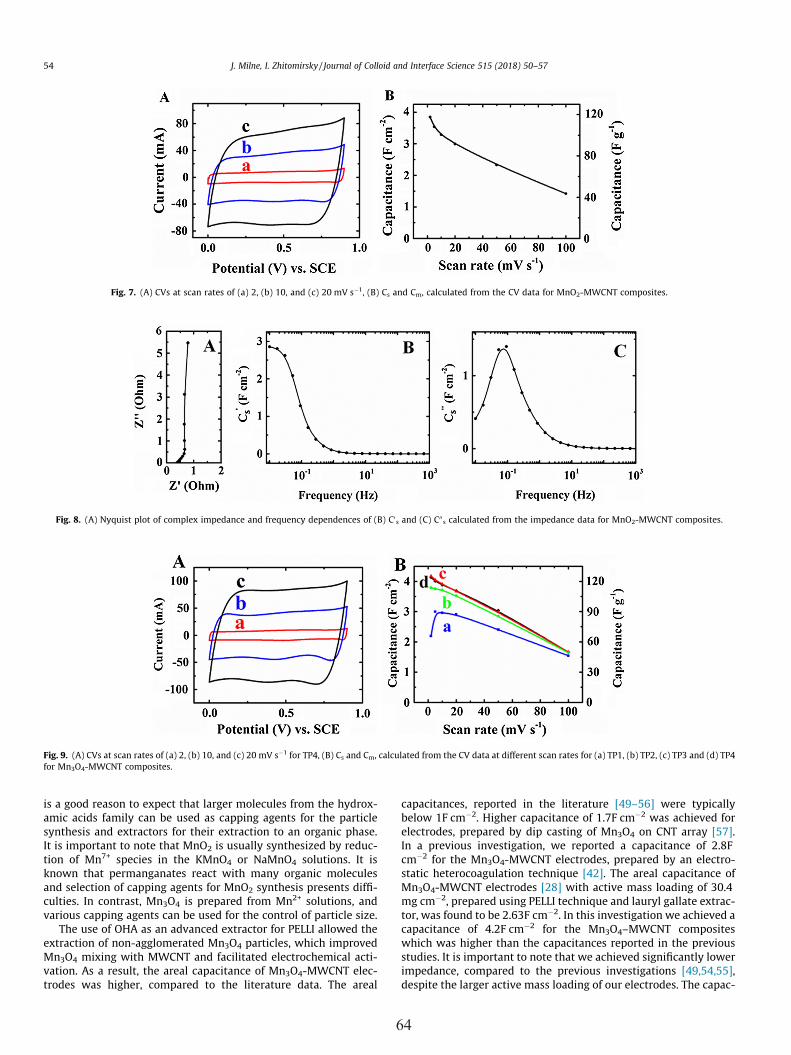
is a good reason to expect that larger molecules from the hydrox-amic acids family can be used as capping agents for the particlesynthesis and extractors for their extraction to an organic phase.It is important to note that MnO2 is usually synthesized by reduc-tion of Mn7+ species in the KMnO4 or NaMnO4 solutions. It isknown that permanganates react with many organic moleculesand selection of capping agents for MnO2 synthesis presents diffi-culties. In contrast, Mn3O4 is prepared from Mn2+ solutions, andvarious capping agents can be used for the control of particle size.
The use of OHA as an advanced extractor for PELLI allowed theextraction of non-agglomerated Mn3O4 particles, which improvedMn3O4 mixing with MWCNT and facilitated electrochemical acti-vation. As a result, the areal capacitance of Mn3O4-MWCNT elec-trodes was higher, compared to the literature data. The areal
capacitances, reported in the literature [49–56] were typicallybelow 1F cm�2. Higher capacitance of 1.7F cm�2 was achieved forelectrodes, prepared by dip casting of Mn3O4 on CNT array [57].In a previous investigation, we reported a capacitance of 2.8Fcm�2 for the Mn3O4-MWCNT electrodes, prepared by an electro-static heterocoagulation technique [42]. The areal capacitance ofMn3O4-MWCNT electrodes [28] with active mass loading of 30.4mg cm�2, prepared using PELLI technique and lauryl gallate extrac-tor, was found to be 2.63F cm�2. In this investigation we achieved acapacitance of 4.2F cm�2 for the Mn3O4–MWCNT compositeswhich was higher than the capacitances reported in the previousstudies. It is important to note that we achieved significantly lowerimpedance, compared to the previous investigations [49,54,55],despite the larger active mass loading of our electrodes. The capac-
Fig. 7. (A) CVs at scan rates of (a) 2, (b) 10, and (c) 20 mV s�1, (B) Cs and Cm, calculated from the CV data for MnO2-MWCNT composites.
Fig. 8. (A) Nyquist plot of complex impedance and frequency dependences of (B) C0s and (C) C00
s calculated from the impedance data for MnO2-MWCNT composites.
Fig. 9. (A) CVs at scan rates of (a) 2, (b) 10, and (c) 20 mV s�1 for TP4, (B) Cs and Cm, calculated from the CV data at different scan rates for (a) TP1, (b) TP2, (c) TP3 and (d) TP4for Mn3O4-MWCNT composites.
54 J. Milne, I. Zhitomirsky / Journal of Colloid and Interface Science 515 (2018) 50–57
64

itances of MnO2-MWCNT and Mn3O4-MWCNT electrodes, obtainedat low scan rates, were comparable with capacitances, calculatedfrom the impedance data at low frequencies.
Previous investigations showed that the capacitances of Mn3O4
based electrodes were typically significantly lower than capaci-tances of MnO2 based electrodes. In contrast, in this investigationwe achieved higher capacitance of Mn3O4-MWCNT electrodes,compared to MnO2-MWCNT, prepared at similar conditions andat the same active mass loadings. It is suggested that reducedagglomeration of Mn3O4 particles, achieved using PELLI, allowedfor better utilization of capacitive properties of this material. Thisresult indicated that Mn3O4 is a promising charge storage materialfor ES and the development of new colloidal and surface modifica-tion techniques can potentially enhance the capacitive perfor-
mance of Mn3O4-MWCNT electrodes. Therefore, it is expectedthat further development of PELLI and the use of other hydroxamicacids and derivatives as capping agents and extractors will allowfurther progress in the development of Mn3O4-MWCNT electrodes.As pointed out above, the application of organic dispersing andcapping agents for the MnO2 synthesis from permanganate solu-tions presents difficulties due to the highly reactive nature of thepermanganate precursors.
4. Conclusions
OHA exhibited remarkable adsorption on MnO2 and Mn3O4 par-ticles due to a bidentate bonding mechanism. The feasibility of theapplication of OHA as an extractor for PELLI has been demon-
Fig. 10. (A) Nyquist plot of complex impedance and frequency dependences of (B) C0s and (C) C00
s calculated from the impedance data for Mn3O4-MWCNT composites afterTP4.
Fig. 11. XPS data for Mn3O4-MWCNT electrodes (A) before testing and (B) after TP4.
Fig. 12. SEM images of Mn3O4-MWCNT electrodes (A) before testing and (B) after TP4.
J. Milne, I. Zhitomirsky / Journal of Colloid and Interface Science 515 (2018) 50–57 55
65

strated. This has opened a path towards new applications of PELLItechnology, because OHA allowed good extraction of particles froman aqueous phase at high pH. Moreover, OHA allowed efficientextraction by strong adsorption on particles not only at thewater-n-butanol interface, but also in the bulk of an aqueousphase. The problem of particle agglomeration was avoided usingPELLI method and OHA as a new extractor. The use of OHA forPELLI facilitated efficient dispersion of particles and their mixingwith MWCNT, which allowed enhanced electrochemical perfor-mance. Moreover, reduced agglomeration facilitated electrochem-ical activation of Mn3O4. Mn3O4-MWCNT electrodes showed a highcapacitance of 4.2F cm�2. The high capacitance was achieved atlow impedance and high active mass loadings, which are beneficialfor supercapacitor applications. Another major finding was thatcapacitance of Mn3O4-MWCNT electrodes was higher than that ofMnO2-MWCNT electrodes at active mass of 33 mg cm�2. This find-ing indicated promising performance of Mn3O4-MWCNT electrodesand paved the way for further advances in the supercapacitor tech-nology. It provides evidence that processing advantages of Mn2+
precursors for Mn3O4 synthesis and mixing with MWCNT, can becombined with benefits of PELLI and other colloidal techniquesfor the fabrication of advanced ES. Especially promising for futureapplications in nanotechnology of composites is a conceptuallynew technique, which involved the use of hydroxamic acids as cap-ping agents for particle synthesis and extractors for PELLI. Webelieve that the further applications of OHA and other hydroxamicacids for PELLI offer a versatile strategy for agglomerate free pro-cessing of other oxide and hydroxide materials, especially for thematerials, which require synthesis at high pH.
Acknowledgements
We acknowledge NSERC Canada for the financial support.
References
[1] R. Pourfaraj, S.J. Fatemi, S.Y. Kazemi, P. Biparva, Synthesis of hexagonalmesoporous MgAl LDH nanoplatelets adsorbent for the effective adsorption ofbrilliant yellow, J. Colloid Interface Sci. 508 (2017) 65–74.
[2] A. Abbasi, M. Hamadanian, M. Salavati-Niasari, S. Mortazavi-Derazkola, Facilesize-controlled preparation of highly photocatalytically active ZnCr2O4 andZnCr2O4/Ag nanostructures for removal of organic contaminants, J. ColloidInterface Sci. 500 (2017) 276–284.
[3] B. Khodadadi, M. Bordbar, M. Nasrollahzadeh, Green synthesis of Pdnanoparticles at Apricot kernel shell substrate using Salvia hydrangea extract:catalytic activity for reduction of organic dyes, J. Colloid Interface Sci. 490(2017) 1–10.
[4] Z. Huang, Y. Zhao, Y. Song, J. Zhao, Synthesis of Co3O4 nanoclusters via anEDTANa4-assisted route for enhanced electrochemical application, J. ColloidInterface Sci. 500 (2017) 142–149.
[5] M.-T. Liu, L.-X. Chen, D.-N. Li, A.-J. Wang, Q.-L. Zhang, J.-J. Feng, One-potcontrolled synthesis of AuPd@Pd core-shell nanocrystals with enhancedelectrocatalytic performances for formic acid oxidation and glyceroloxidation, J. Colloid Interface Sci. 508 (2017) 551–558.
[6] Y. Xu, J. Sheng, X. Yin, J. Yu, B. Ding, Functional modification of breathablepolyacrylonitrile/polyurethane/TiO2 nanofibrous membranes with robustultraviolet resistant and waterproof performance, J. Colloid Interface Sci. 508(2017) 508–516.
[7] R. Jin, Y. Cui, Q. Wang, G. Li, Facile fabrication of CNTs@C@MoSe2@Se hybridswith amorphous structure for high performance anode in lithium-ionbatteries, J. Colloid Interface Sci. 508 (2017) 435–442.
[8] D. Santos, D.M. Silva, P.S. Gomes, M.H. Fernandes, J.D. Santos, V. Sencadas,Multifunctional PLLA-ceramic fiber membranes for bone regenerationapplications, J. Colloid Interface Sci. 504 (2017) 101–110.
[9] S. Sirohi, R. Singh, N. Jain, B. Pani, K. Dutt, R. Nain, Synthesis andcharacterization of multifunctional ZnO/polyester green composite films, J.Polym. Res. 24 (2017) 193 (1-10).
[10] J.-Y. Chung, J.-G. Lee, Y.-K. Baek, P.-W. Shin, Y.-K. Kim, Magnetic field-inducedenhancement of thermal conductivities in polymer composites by linearclustering of spherical particles, Compos. Part B: Eng. 136 (2018) 215–221.
[11] Y. Su, I. Zhitomirsky, Hybrid MnO2/carbon nanotube-VN/carbon nanotubesupercapacitors, J. Power Sources 267 (2014) 235–242.
[12] K. Rezwan, Q.Z. Chen, J.J. Blaker, A.R. Boccaccini, Biodegradable and bioactiveporous polymer/inorganic composite scaffolds for bone tissue engineering,Biomaterials 27 (2006) 3413–3431.
[13] T. Wang, J.L. Keddie, Design and fabrication of colloidal polymernanocomposites, Adv. Colloid Interface Sci. 147–148 (2009) 319–332.
[14] I. Zhitomirsky, L. Gal-Or, Formation of hollow fibers by electrophoreticdeposition, Mater. Lett. 38 (1999) 10–17.
[15] O.O. Van der Biest, L.J. Vandeperre, Electrophoretic deposition of materials,Annu. Rev. Mater. Sci. 29 (1999) 327–352.
[16] X. Zhao, C. Hinchliffe, C. Johnston, P.J. Dobson, P.S. Grant, Spray deposition ofpolymer nanocomposite films for dielectric applications, Mater. Sci. Eng. B:Solid-State Mater. Adv. Technol. 151 (2008) 140–145.
[17] F. Mauvy, P. Lenormand, C. Lalanne, F. Ansart, J.M. Bassat, J.C. Grenier,Electrochemical characterization of YSZ thick films deposited by dip-coatingprocess, J. Power Sources 171 (2007) 783–788.
[18] R. Chen, M.S. Ata, X. Zhao, A. Clifford, I. Puri, I. Zhitomirsky, Strategies forliquid-liquid extraction of oxide particles for applications in supercapacitorelectrodes and thin films, J. Colloid Interface Sci. 499 (2017) 1–8.
[19] K.S. Mayya, F. Caruso, Phase transfer of surface-modified gold nanoparticles byhydrophobization with alkylamines, Langmuir 19 (2003) 6987–6993.
[20] M. Karg, N. Schelero, C. Oppel, M. Gradzielski, T. Hellweg, R. von Klitzing,Versatile phase transfer of gold nanoparticles from aqueous media to differentorganic media, Chem.-A Euro. J. 17 (2011) 4648–4654.
[21] A. Kumar, H. Joshi, R. Pasricha, A. Mandale, M. Sastry, Phase transfer of silvernanoparticles from aqueous to organic solutions using fatty amine molecules,J. Colloid Interface Sci. 264 (2003) 396–401.
[22] N. Gaponik, D.V. Talapin, A.L. Rogach, A. Eychmuller, H. Weller, Efficient phasetransfer of luminescent thiol-capped nanocrystals: from water to nonpolarorganic solvents, Nano Lett. 2 (2002) 803–806.
[23] J. Erler, S. Machunsky, P. Grimm, H.-J. Schmid, U.A. Peuker, Liquid-liquid phasetransfer of magnetite nanoparticles-evaluation of surfactants, Powder Technol.247 (2013) 265–269.
[24] B. Hu, Y. Nakahiro, T. Wakamatsu, The effect of organic solvents on therecovery of fine mineral particles by liquid-liquid extraction, Miner. Eng. 6(1993) 731–742.
[25] W. Cheng, E. Wang, Size-dependent phase transfer of gold nanoparticles fromwater into toluene by tetraoctylammonium cations: a wholly electrostaticinteraction, J. Phys. Chem. B 108 (2004) 24–26.
[26] H. Yao, O. Momozawa, T. Hamatani, K. Kimura, Phase transfer of goldnanoparticles across a water/oil interface by stoichiometric ion-pairformation on particle surfaces, Bull. Chem. Soc. Jpn. 73 (2000) 2675–2678.
[27] C. Wallar, T. Zhang, K. Shi, I. Zhitomirsky, Synthesis of metal and metal oxidenanoparticles, liquid-liquid extraction and application in supercapacitors,Colloids Surf. A: Physicochem. Eng. Aspects 500 (2016) 195–202.
[28] R. Poon, X. Zhao, M. Ata, A. Clifford, I. Zhitomirsky, Phase transfer of oxideparticles for application in thin films and supercapacitors, Ceram. Int. 43(2017) 8314–8320.
[29] A. Clifford, M. Ata, I. Zhitomirsky, Synthesis, liquid-liquid extraction anddeposition of hydroxyapatite nanorod composites, Mater. Lett. 201 (2017)140–143.
[30] R. Chen, R. Poon, R.P. Sahu, I.K. Puri, I. Zhitomirsky, MnO2-carbon nanotubeelectrodes for supercapacitors with high active mass loadings, J. Electrochem.Soc. 164 (2017) A1673–A1678.
[31] R. Chen, M.S. Ata, X. Zhao, I. Puri, I. Zhitomirsky, Liquid-liquid extraction ofoxide particles and application in supercapacitors, J. Mater. Res. 32 (2017) 1–9.
[32] T. Zhang, X. Zhao, R. Poon, A. Clifford, R. Mathews, I. Zhitomirsky, Synthesis andliquid-liquid extraction of non-agglomerated Al (OH)3 particles for depositionof cellulose matrix composite films, J. Colloid Interface Sci. 508 (2017) 49–55.
[33] J.P. Folkers, C.B. Gorman, P.E. Laibinis, S. Buchholz, G.M. Whitesides, R.G.Nuzzo, Self-assembled monolayers of long-chain hydroxamic acids on thenative oxide of metals, Langmuir 11 (1995) 813–824.
[34] C. Wallar, R. Poon, I. Zhitomirsky, High areal capacitance of V2O3-carbonnanotube electrodes, J. Electrochem. Soc. 164 (2017) A3620–A3627.
[35] J. Wang, H.-W. Cheng, H.-B. Zhao, W.-Q. Qin, G.-Z. Qiu, Flotation behavior andmechanism of rutile with nonyl hydroxamic acid, Rare Met. 35 (2016) 419–424.
[36] A. Sarvaramini, D. Azizi, F. Larachi, Hydroxamic acid interactions with solvatedcerium hydroxides in the flotation of monazite and bastnasite-experimentsand DFT study, Appl. Surf. Sci. 387 (2016) 986–995.
[37] J. Eisenlauer, E. Matijevic, Interactions of metal hydrous oxides with chelatingagents. II. a-Fe2O3—low molecular and polymeric hydroxamic acid species, J.Colloid Interface Sci. 75 (1980) 199–211.
[38] R. Natarajan, D. Fuerstenau, Adsorption and flotation behavior of manganesedioxide in the presence of octyl hydroxamate, Int. J. Miner. Process. 11 (1983)139–153.
[39] M. Giza, P. Thissen, G. Grundmeier, Adsorption kinetics of organophosphonicacids on plasma-modified oxide-covered aluminum surfaces, Langmuir 24(2008) 8688–8694.
[40] E.S. Dzunuzovic, J.V. Dzunuzovic, A.D. Marinkovic, M.T. Marinovic-Cincovic, K.B. Jeremic, J.M. Nedeljkovic, Influence of surface modified TiO2 nanoparticlesby gallates on the properties of PMMA/TiO2 nanocomposites, Eur. Polym. J. 48(2012) 1385–1393.
[41] K. Shi, I. Zhitomirsky, Influence of current collector on capacitive behavior andcycling stability of Tiron doped polypyrrole electrodes, J. Power Sources 240(2013) 42–49.
[42] M. Ata, J. Milne, I. Zhitomirsky, Fabrication of Mn3O4-carbon nanotubecomposites with high areal capacitance using cationic and anionicdispersants, J. Colloid Interface Sci. 512 (2018) 758–766.
56 J. Milne, I. Zhitomirsky / Journal of Colloid and Interface Science 515 (2018) 50–57
66

[43] P. Suktha, N. Phattharasupakun, P. Dittanet, M. Sawangphruk, Charge storagemechanisms of electrospun Mn3O4 nanofibres for high-performancesupercapacitors, RSC Adv. 7 (2017) 9958–9963.
[44] B.G.S. Raj, A.M. Asiri, J.J. Wu, S. Anandan, Synthesis of Mn3O4 nanoparticles viachemical precipitation approach for supercapacitor application, J. AlloysCompd. 636 (2015) 234–240.
[45] W. Dong, J.S. Sakamoto, B. Dunn, Electrochemical properties of vanadiumoxide aerogels, Sci. Technol. Adv. Mater. 4 (2003) 3–11.
[46] W. Dong, D.R. Rolison, B. Dunn, Electrochemical properties of high surfacearea vanadium oxide aerogels, Electrochem. Solid-State Lett. 3 (2000) 457–459.
[47] Y.U. Jeong, A. Manthiram, Nanocrystalline manganese oxides forelectrochemical capacitors with neutral electrolytes, J. Electrochem. Soc. 149(2002) A1419–A1422.
[48] R.N. Reddy, R.G. Reddy, Sol-gel MnO2 as an electrode material forelectrochemical capacitors, J. Power Sources 124 (2003) 330–337.
[49] A.A. Yadav, Influence of electrode mass-loading on the properties of spraydeposited Mn3O4 thin films for electrochemical supercapacitors, Thin SolidFilms 608 (2016) 88–96.
[50] H. Cheng, H.M. Duong, D. Jewell, Three dimensional manganese oxide oncarbon nanotube hydrogels for asymmetric supercapacitors, RSC Adv. 6 (2016)36954–36960.
[51] X.-J. Li, Z.-W. Song, Y. Zhao, Y. Wang, X.-C. Zhao, M. Liang, W.-G. Chu, P. Jiang, Y.Liu, Vertically porous nickel thin film supported Mn3O4 for enhanced energystorage performance, J. Colloid Interface Sci. 483 (2016) 17–25.
[52] D. Dubal, D. Dhawale, R. Salunkhe, V. Fulari, C. Lokhande, Chemical synthesisand characterization of Mn3O4 thin films for supercapacitor application, J.Alloys Compd. 497 (2010) 166–170.
[53] A. Radhamani, R. Rao, Tunable supercapacitance of electrospun Mn3O4 beadedchains via charge-discharge cycling and control parameters, Appl. Surf. Sci.403 (2017) 601–611.
[54] Y. Hu, C. Guan, G. Feng, Q. Ke, X. Huang, J. Wang, Flexible asymmetricsupercapacitor based on structure-optimized Mn3O4/reduced graphene oxidenanohybrid paper with high energy and power density, Adv. Funct. Mater. 25(2015) 7291–7299.
[55] Y. Qiao, Q. Sun, J. Xi, H. Cui, Y. Tang, X. Wang, A modified solvothermalsynthesis of porous Mn3O4 for supercapacitor with excellent rate capabilityand long cycle life, J. Alloys Compd. 660 (2016) 416–422.
[56] M.P. Clark, W. Qu, D.G. Ivey, Nanostructured manganese oxide and manganeseoxide/polyethylenedioxythiophene rods electrodeposited onto nickel foam forsupercapacitor applications, J. Appl. Electrochem. 47 (2017) 39–49.
[57] X. Cui, F. Hu, W. Wei, W. Chen, Dense and long carbon nanotube arraysdecorated with Mn3O4 nanoparticles for electrodes of electrochemicalsupercapacitors, Carbon 49 (2011) 1225–1234.
J. Milne, I. Zhitomirsky / Journal of Colloid and Interface Science 515 (2018) 50–57 57
67

M.A.Sc Thesis – Jordan Milne; McMaster University – Materials Science & Engineering.
68
Chapter 7: Phase Transfer of Oxide Particles Using Hydroxamic
Acid Derivatives and Application for Supercapacitors
Reprinted article with permission from J. Milne, R. M. E. Silva, Z. Z. Wang, and I.
Zhitomirsky, “Phase transfer of oxide particles using hydroxamic acid derivatives and
application for supercapacitors,” Ceram. Int., vol. 45, no. 2, pp. 2498–2503, 2018. DOI:
10.1016/j.ceramint.2018.10.177
Author’s Contributions
• Synthesis of electrode materials
• Electrochemical testing of electrodes
• FTIR and XRD of materials
• Literature evaluation
• Preparation of manuscript draft

Contents lists available at ScienceDirect
Ceramics International
journal homepage: www.elsevier.com/locate/ceramint
Phase transfer of oxide particles using hydroxamic acid derivatives andapplication for supercapacitors
J. Milne, R.M.E. Silva, Z.Z. Wang, I. ZhitomirskyDepartment of Materials Science and Engineering, McMaster University, Hamilton, Ontario, Canada L8S4L7
A R T I C L E I N F O
Keywords:SupercapacitorCerium oxideZinc oxideIron hydroxideExtractionDispersion
A B S T R A C T
Particle extraction through liquid-liquid interface (PELLI) methods are developed for the colloidal processing ofZnO, CeO2 and FeOOH particles. The direct transfer of the particles from an aqueous synthesis medium to adevice processing medium allows for reduced nanoparticle agglomeration, because drying and re-dispersionprocesses are avoided. Different PELLI methods are developed, which are based on the use of chelating hy-droxamates molecules, such as octanohydroxamic acid (OCHA) and bufexamac (BFXM) as extractors. OCHA andBFXM show strong adsorption on the ZnO, CeO2 and FeOOH particles due to chelating bonding mechanisms andallow for efficient particle extraction from water to organic solvents. Bottom–up and top-down methods areused, depending on the density of the organic solvents. OCHA shows improved extraction of particles, comparedto BFXM due to the difference in the chemical structure. The unique feature of hydroxamates is related to theirpH-dependent solubility and their strong adsorption on particles at high pH, despite the electrostatic repulsion ofthe negatively charged particles and dissociated hydroxamic acids. It is found that OCHA can be used as acapping agent for particle synthesis and an extractor for their extraction to an organic phase. The advantages ofPELLI methods are demonstrated by the fabrication and testing of FeOOH-carbon nanotube electrodes for su-percapacitors, which show enhanced performance and high capacitance at high active mass loading. The en-hanced electrochemical performance is achieved due to reduced particle agglomeration, which allows improvedparticle mixing with conductive carbon nanotubes. The capacitive properties are investigated at different charge-discharge rates. The impedance spectroscopy data shows dependence of capacitance on electrode potential andprovides an insight into the strategies for further improvement of electrode performance.
1. Introduction
Liquid-liquid interface (LLI) phenomena have attracted significantattention for surface modification and colloidal processing of ceramicmaterials. LLI presents a unique environment for controlled synthesis ofnanostructured oxides and hydroxides, such as MnO2 [1], CuO [2,3],TiO2 [4], ZnO [2,3], and Fe2O3 [2]. Moreover, LLI is a versatile plat-form for self-assembly of oxide nanoparticles [5] and formation of or-dered 2-D structures. LLI allows easy access of organic surfactants to thenanoparticle surface and facilitates the formation of modified particles.Of particular interest are particle extraction through liquid-liquid in-terface (PELLI) methods, which are now being investigated for the di-rect transfer of particles synthesized in aqueous solutions to variousorganic solvents [1,6–9].
The development of PELLI has been motivated by the need to avoidthe formation of hard agglomerates. It is in this regard that manyprocessing technologies involve synthesis of particles in aqueous solu-tions of metal salts and then particle transfer to organic solvents for the
fabrication of films and devices. A traditional approach involves dryingof the synthesized particles and their re-dispersion in an organic sol-vent. However, particle drying usually causes agglomeration, which isgoverned by the reduction of surface energy and condensation of sur-face OH groups. In contrast, PELLI allows direct particle transfer from asynthesis medium to a device processing medium. The non-aqueoussuspensions of transferred particles were used for the manufacturing ofnanostructured composites [1,6,7]. From the previous studies it isevident that the dispersion of non-agglomerated particles in organicsolvents facilitated their mixing with various water-insoluble additivesand polymers for the fabrication of advanced thin film and bulk devices[1].
It was recognized that PELLI applications require the use of ex-tractor molecules, which must be strongly adsorbed on particles[1,6,7]. The adsorption mechanisms are based on ion-pair [10], elec-trostatic [11] and covalent interactions [12]. The most promising re-sults were obtained using chelating extractors, which created strong bi-or tri-dentate bonds [1,13]. Therefore, the general focus of PELLI
https://doi.org/10.1016/j.ceramint.2018.10.177Received 20 September 2018; Received in revised form 18 October 2018; Accepted 19 October 2018
E-mail address: [email protected] (I. Zhitomirsky).
69

development has been on the search for efficient chelating moleculesand analysis of their adsorption on various materials.
Hydroxamic acids and their derivatives are promising molecules forthe use as extractors for PELLI. Hydroxamates exhibited strong ad-sorption on rare earth oxides [14], titania [15,16], zirconia [17], ceria[18], copper [17] and iron oxides [19,20]. The unique adsorptionproperties of hydroxamates were used in the mineral flotation[14,21–23], where various hydroxamate molecules served as collectors.Hydroxamates adsorb chemically on inorganic surfaces, forming stablecomplexes with surface metal cations [24]. The strong interaction ofhydroxamic acids with mineral particles allowed high flotation effi-ciency and selectivity [25]. Investigations revealed the influence ofmolecular structure of the hydroxamic acid derivatives on the flotationefficiency [26]. The comparison of different long chain (C18) hydro-xamic acids as collectors showed that the flotation yield is dependenton the number of double bonds in the chemical structure of the col-lector molecules [26]. At low concentrations, the interactions of hy-droxamic acids with different inorganic surfaces can result in verticallyor horizontally oriented monolayers [27]. Density functional theory(DFT) simulations were performed to analyze the adsorption mechan-isms [18]. DFT studies showed the influence of the molecular structureof hydroxamates on their adsorption on particles [28]. The mineralsflotation literature examined hydroxamate behavior at water-air in-terface [29]. The application of hydroxamates for PELLI requires un-derstanding of their behavior at the interface of immiscible fluids, suchas water and organic solvents.
Hydroxamates are especially promising materials for PELLI appli-cations, because they show strong adsorption on metal oxide surfaces athigh pH [30–32] above the isoelectric points of various oxide materials,despite the electrostatic repulsion of the negatively charged particlesand hydroxamic acids. Therefore, inorganic particles precipitated fromaqueous solutions at high pH can potentially be extracted by PELLI
using hydroxamate extractors. Recently, octanohydroxamic acid(OCHA) was used for extraction of manganese oxides [33]. These stu-dies have generated interest in the application of OCHA for extractionof various functional oxide and hydroxide materials and investigationof other hydroxamate molecules for PELLI applications. It is importantto note that adsorbed hydroxamates imparted advanced functionalproperties to ceramic particles and allowed the fabrication of materialswith enhanced hydrophobicity and wear resistance [34], advancedphotovoltaic and charge transfer properties [35–38].
The goal of this investigation was the synthesis and extraction ofZnO, CeO2 and FeOOH using hydroxamate molecules, such as OCHAand bufexamac (BFXM). We analyzed the influence of the molecularstructure of OCHA and BFXM on the particle extraction and proposeddifferent extraction methods and mechanisms. Bottom-up (BU) and top-down (TD) strategies were used. The FeOOH material showed pro-mising performance for the fabrication of FeOOH – multiwalled carbonnanotube (MCNT) supercapacitor (SCap) electrodes for operation in anegative potential window. The use of PELLI allowed good electro-chemical performance at high active mass (AM).
2. Experimental procedures
OCHA and BFXM (TCI America), 1-butanol, dichloromethane,polyvinylbutyral, Zn(NO3)2·6H2O, Ce(NO3)3·6H2O, Na2SO4, NaOH,FeCl3·6H2O (Aldrich), MCNT (4 nm ID, 13 nm OD, 1–2 µm length,Bayer, Germany), and Ni foam current collectors (Vale Canada, 95%porosity) were used. ZnO and CeO2 were prepared from Zn(NO3)2 andCe(NO3)3 solutions, respectively, as it was described in the previousinvestigation [6]. The procedure for the fabrication of FeOOH wasbased on a chemical precipitation method [39] using 0.05M FeCl3 so-lutions. The pH of the solution was adjusted to pH=7 by 0.01Maqueous NaOH solution.
1-butanol and dichloromethane were used as particle-receiving or-ganic liquids for the BU and TD PELLI methods, respectively. In theextraction method 1 (EMT1), the extractor molecules were dissolved inthe organic liquids and added to the aqueous phase, containing as-precipitated ZnO, CeO2 and FeOOH particles. After stirring, the parti-cles were transferred to the organic solvents. In the extraction method 2(EMT2), the extractor molecules were dissolved in aqueous NaOH so-lutions, which were added to the solutions of metal salts. In thismethod, the synthesis and particle modification were performed in one-step procedure, where the extractor molecules were used as cappingagents for the synthesis. The addition of the organic solvent resulted inthe particle transfer to the organic phase.
X-ray diffraction (XRD) studies were performed using a Nicolet I2diffractometer and CuKα radiation. FTIR studies of powder sampleswere carried out using a Bruker Vertex 70 spectrometer. The equipmentand procedures for the investigation of capacitive properties were de-scribed in a previous investigation [6]. The active mass (AM) of
Fig. 1. X-ray diffraction patterns of (a) ZnO (• - JCPDS file 36–1451), (b) CeO2
(▼ - JCPDS file 34–0394), (c) FeOOH.
Fig. 2. (A) Structures of (a) OCHA and (b) BFXM and (B) adsorption of (a) OCHA and (b) BF on particles, involving chelation of surface metal atoms (M).
J. Milne et al.
70

electrodes and electrode area were 39.6mg cm−2 and 1 cm2, respec-tively.
3. Results and discussion
X-ray diffraction studies revealed the formation of crystalline ZnOand CeO2 phases, whereas FeOOH was amorphous (Fig. 1). OCHA and
BFXM were used as extractors for PELLI. The chemical structures ofOCHA and BFXM include a carbonyl group and NOH2 group(Fig. 2A(a,b)). The structure of OCHA contains a hydrophobic alkylgroup, whereas the structure of BFXM contains an aromatic group and ashorter alkyl group. The mechanism of hydroxamates adsorption onmaterials has been described in the literature [15]. It is based on thechelation chemistry and involves carbonyl and NOH2 groups. Fig. 2B(a,b) shows adsorption of OCHA and BFXM on metal oxide particles.
ZnO, CeO2 and FeOOH were extracted by EMT1 using OCHA andBFXM. Fig. 3 shows extraction of ZnO by EMT1 using OCHA. Thesuspensions of as-prepared ZnO were unstable (Fig. 3A,B) and showedfast particle precipitation immediately after stirring. The extraction canbe based on two different mechanisms or a combination of both. Itshould be noted that similar to other head-tail surfactants, the OCHAand BFXM molecules can be accumulated at the liquid-liquid interface.In the extraction mechanism1 (EMC1), the extractor molecules wereaccumulated at the LLI (Fig. 3C) and adsorbed on the particles(Fig. 3D), which were then extracted to the organic phase (Fig. 3G,H).In the extraction mechanism 2 (EMC2), the extractor molecules pene-trated the LLI (Fig. 3E), adsorbed on the particles in the aqueous phase(Fig. 3F) and then extracted to the organic phase (Fig. 3G,H). Fig. 4shows that CeO2 and FeOOH can also be extracted by EMT1 usingOCHA. EMT1 has also been utilized for the extraction of ZnO, CeO2 andFeOOH using BFXM (Supplementary information, Fig. S1). However,OCHA showed higher extraction efficiency, which was close to 100%. Itis important to note that the OCHA and BFXM molecules exhibit a pH-dependent solubility. The solubility of such molecules increases withincreasing pH. The synthesis of ZnO, CeO2 and FeOOH was performed
Fig. 3. (A) As-precipitated ZnO, (B-G) schematic of EMT1: (B-C-D-G) EMC 1 and (B-E-F-G) EMC 2, (H) extracted ZnO, arrow shows LLI.
Fig. 4. (A) As-precipitated FeOOH and (B) FeOOH extracted by EMT1; (C) as-precipitated CeO2 and (D) CeO2 extracted by EMT1.
Fig. 5. FTIR spectra of (a) as-received OCHA, and materials extracted by EMT1(b) ZnO, (c) CeO2 and (d) FeOOH.
J. Milne et al.
71

at pH 10, 11 and 7, respectively. Therefore, the extraction of ZnO, CeO2
and FeOOH in EMT1 involved different contributions of EMC1 andEMC2. It is important to note that CeO2 was extracted at relatively high
pH (pH=11) which was far above the isoelectric point of CeO2 (pH=6)[40] despite the electrostatic repulsion of negatively charged hydro-xamic acids and CeO2 particles. This observation indicates strong
Fig. 6. (A-G) Extraction of ZnO by EMT2: (A-C) schematic of synthesis in aqueous phase by addition of (A) OCHA solution in alkali to (B) aqueous solution of Zn(NO3)2, (C) formation of ZnO particles, containing adsorbed OCHA, (C,D) schematic of down-up extraction and (E) image of extracted ZnO, arrow shows LLI (C, F)schematic of top-down extraction and (G) image of extracted ZnO, arrow shows LLI.
Fig. 7. (A) CV at 10mV s−1 and (B) capacitance for FeOOH- MCNT electrodes with AM of 39.6 mg cm−2 prepared (a) using PELLI and (b) by traditional drying andre-dispersion method.
Fig. 8. (A) Nyquist and (B, C) Bode diagrams of (A) impedance and (B, C) components of complex capacitance for FeOOH- MCNT electrode with AM of 39.6 mg cm−2
at open circuit conditions.
J. Milne et al.
72

adsorption of the hydroxamic acids on the particles, which results fromthe chelating properties of the molecules.
The adsorption of the extractor molecules was confirmed by theFTIR analysis of the extracted particles. The spectra of OCHA (Fig. 5)and BFXM (Supplementary information, Fig. S2) showed absorptions inthe range of 2800–3000 cm−1, which resulted from vibrations of CH3
and CH2 groups [33]. The particles of ZnO, CeO2 and FeOOH, extractedusing OCHA (Fig. 5) and BFXM (Supplementary information, Fig. S2)showed similar absorptions, which confirmed OCHA and BFXM ad-sorption.
The solubility of OCHA and BFXM in alkali allowed PELLI usingEMT2. Fig. 6 shows different steps in the EMT2, which is based ondissolution of OCHA in alkali and precipitation of ZnO in the presenceof OCHA. In this approach OCHA served as a capping agent for thesynthesis and phase transfer agent in the extraction. Fig. 6 indicatesthat BU and TD strategies can be used, depending on the solvent den-sity.
The FeOOH particles, extracted by EMT1, were used for the fabri-cation of supercapacitor electrodes. For comparison, the electrodes ofsimilar composition and mass were prepared by the traditional strategy,which involved drying of the precipitated FeOOH particles and their re-dispersion in an organic phase, containing dissolved binder and MCNT.It should be noted that the dissolution of a water insoluble polymerbinder in an organic solvent is critical for the fabrication of compositesfor aqueous SCap electrodes with reduced binder content. We foundthat drying of the FeOOH particles resulted in the formation of hardagglomerates, which was attributed to the condensation of OH groupson the particle surface and formation of oxo-bridges. Another driving
force for particle agglomeration is the reduction of surface area andsurface energy. The mixing of agglomerated particles with MCNT pre-sented difficulties. However, good dispersion of FeOOH and theirmixing with MCNT is important for the fabrication of electrodes withhigh capacitance and low resistance. In the PELLI method, the particleswere transferred directly from the aqueous phase to the organic phaseand the drying stage was avoided.
Fig. 7A shows cyclic voltammetry data for the FeOOH-MCNT (20%MCNT) composites. The integral capacitance was calculated in thewindow of 0.0–0.8 V versus saturated calomel electrode (Fig. 7B).Testing results showed that a significant improvement of the capacitivebehavior can be achieved using PELLI. The composite electrodes pre-pared using PELLI showed the highest areal capacitance of 3.3 F cm−2
at low scan rates. The electrodes showed good capacitance retention athigh scan rate, which was about 50% at a scan rate of 100mV s−1. In,contrast, the electrodes, prepared by traditional drying and re-disper-sion method showed significantly lower CV area and lower capacitance,especially at high scan rates (Fig. 7).
The capacitive behavior of the electrodes has also been tested usingimpedance spectroscopy. Such measurements are usually performed atopen circuit potential conditions at low AC voltages [41–43]. Theanalysis of the Nyquist plot (Fig. 8A) showed low resistance, which isbeneficial for SCap applications. The slop in the plot was close to 90°and indicated capacitive behavior. The real and imaginary parts of thecomplex AC capacitance (Fig. 8B,C) showed a relaxation type disper-sion, which resulted in the reduction of the real part of capacitance (CS′)with increasing frequency and a relaxation maximum in the imaginarypart (CS′′). Turning again to the CV data (Fig. 7A(a)), it should be notedthat differential AC capacitance is dependent on the electrode potential,because the CV shape deviates significantly from the ideal box shape.Therefore, impedance measurements have also been performed at dif-ferent electrode potentials. The electrodes tested at applied potentialsof −0.8 to 0.2 V versus SCE showed relatively low resistance R=Z′,however significantly higher resistance was obtained at 0.0 V versusSCE (Fig. 9). The differential AC capacitance CS′, measured at lowfrequencies decreased with increasing electrode potential (Fig. 10A)from −0.8 to 0.0 V versus SCE. The frequency dependences of thecomponents of complex capacitance showed relaxation type disper-sions. The relaxation frequency, corresponding to maximum in CS′′ in-creased with increasing electrode potential in the range of −0.8 to0.2 V versus SCE (Fig. 10B). Testing results indicated that behavior ofthe electrodes must be improved in the potential range of −0.2 to 0.0 Vversus SCE. This problem can potentially be addressed by the devel-opment of composites. The application of PELLI for different materialscan be used for their co-extraction and improved mixing.
Fig. 9. Nyquist diagrams for FeOOH-MCNT electrode with AM of 39.6 mg cm−2
at electrode potentials of (a)−0.8, (b)−0.5, (c)−0.2 and (d) 0.0 V versus SCE,inset shows high frequency range.
Fig. 10. Bode diagrams of complex capacitance for FeOOH-MCNT electrode with AM of 39.6 mg cm−2 at electrode potentials of (a)−0.8, (b) −0.5, (c)−0.2 and (d)0.0 V versus SCE.
J. Milne et al.
73

4. Conclusions
OCHA and BFXM allowed extraction of ZnO, CeO2 and FeOOHparticles from water to organic solvents. OCHA showed enhanced ex-traction efficiency, compared to BFXM, due to the difference in theirchemical structure. EMT1 and EMT2 were developed, which are basedon different mechanisms. PELLI methods allowed for BU and TD ex-tractions. The use of hydroxamates allowed for efficient extraction fromaqueous suspensions at high pH, despite of electrostatic repulsion of thenegatively charged dissociated hydroxamate molecules and negativelycharged particles. It was found that OCHA can be used as a cappingagent for particle synthesis and as an extractor for their extraction fromwater to an organic phase. The advantages of PELLI have been de-monstrated by the comparison of the electrochemical performance ofFeOOH-MCNT electrodes, prepared using PELLI and by a traditionaldrying and re-dispersion method. The electrodes, prepared using PELLIshowed improved capacitive behavior due to reduced FeOOH agglom-eration, which facilitated FeOOH mixing with conductive MCNT. TheFeOOH-MCNT composites showed promising performance for applica-tion in negative electrodes of SCap. The CV data, coupled with im-pedance analysis at different electrode potentials showed that electro-chemical performance must be improved in the potential range of −0.2to 0.0 V versus SCE. PELLI is a promising method for the fabrication ofcomposites with improved performance.
Acknowledgements
The authors gratefully acknowledge the Natural Sciences andEngineering Research Council of Canada for the financial support.
Appendix A. Supporting information
Supplementary data associated with this article can be found in theonline version at doi:10.1016/j.ceramint.2018.10.177.
References
[1] C. Wallar, T. Zhang, K. Shi, I. Zhitomirsky, Synthesis of metal and metal oxidenanoparticles, liquid–liquid extraction and application in supercapacitors, ColloidsSurf. A: Physicochem. Eng. Asp. 500 (2016) 195–202.
[2] C. Rao, S. Vivekchand, K. Biswas, A. Govindaraj, Synthesis of inorganic nanoma-terials, Dalton Trans. (2007) 3728–3749.
[3] C. Rao, K. Kalyanikutty, The liquid–liquid interface as a medium to generate na-nocrystalline films of inorganic materials, Acc. Chem. Res. 41 (2008) 489–499.
[4] T. Narabe, M. Hagiwara, S. Fujihara, A biphasic sol–gel route to synthesize anataseTiO2 particles under controlled conditions and their DSSC application, J. AsianCeram. Soc. 5 (2017) 427–435.
[5] A. Toor, T. Feng, T.P. Russell, Self-assembly of nanomaterials at fluid interfaces,Eur. Phys. J. E 39 (2016) 57.
[6] R. Chen, Z.Z. Wang, R.P. Sahu, I.K. Puri, I. Zhitomirsky, Influence of molecularstructure of extractor molecules on liquid-liquid extraction of oxide particles andproperties of composites, Ceram. Int. 44 (2018) 15714–15720.
[7] R. Poon, X. Zhao, M. Ata, A. Clifford, I. Zhitomirsky, Phase transfer of oxide par-ticles for application in thin films and supercapacitors, Ceram. Int. 43 (2017)8314–8320.
[8] J. Erler, S. Machunsky, P. Grimm, H.-J. Schmid, U.A. Peuker, Liquid–liquid phasetransfer of magnetite nanoparticles—evaluation of surfactants, Powder Technol.247 (2013) 265–269.
[9] R. Bhandary, J. Alauzun, P. Hesemann, A. Stocco, M. In, P.H. Mutin, Phase transferof TiO2 nanoparticles from water to ionic liquid triggered by phosphonic acidgrafting, Soft Matter 13 (2017) 8023–8026.
[10] H. Yao, O. Momozawa, T. Hamatani, K. Kimura, Phase transfer of gold nano-particles across a water/oil interface by stoichiometric ion-pair formation on par-ticle surfaces, Bull. Chem. Soc. Jpn. 73 (2000) 2675–2678.
[11] W. Cheng, E. Wang, Size-dependent phase transfer of gold nanoparticles from waterinto toluene by tetraoctylammonium cations: a wholly electrostatic interaction, J.Phys. Chem. B. 108 (2004) 24–26.
[12] M. Karg, N. Schelero, C. Oppel, M. Gradzielski, T. Hellweg, R. von Klitzing, Versatilephase transfer of gold nanoparticles from aqueous media to different organic media,Chem.-A Eur. J. 17 (2011) 4648–4654.
[13] R. Chen, R. Poon, R.P. Sahu, I.K. Puri, I. Zhitomirsky, MnO2-carbon nanotubeelectrodes for supercapacitors with high active mass loadings, J. Electrochem. Soc.164 (2017) A1673–A1678.
[14] J. Cui, G.A. Hope, A.N. Buckley, Spectroscopic investigation of the interaction ofhydroxamate with bastnaesite (cerium) and rare earth oxides, Miner. Eng. 36(2012) 91–99.
[15] J. Wang, H.-W. Cheng, H.-B. Zhao, W.-Q. Qin, G.-Z. Qiu, Flotation behavior andmechanism of rutile with nonyl hydroxamic acid, Rare Met. 35 (2016) 419–424.
[16] B. Rudshteyn, C.F. Negre, R.S. Oliboni, A. Monti, J. Chen, R.H. Crabtree, L.G. Rego,V.S. Batista, Inferring Protonation States of Hydroxamate Adsorbates on TiO2
Surfaces, J. Phys. Chem. C 121 (2017) 11985–11990.[17] J.P. Folkers, C.B. Gorman, P.E. Laibinis, S. Buchholz, G.M. Whitesides, R.G. Nuzzo,
Self-assembled monolayers of long-chain hydroxamic acids on the native oxide ofmetals, Langmuir 11 (1995) 813–824.
[18] A. Sarvaramini, D. Azizi, F. Larachi, Hydroxamic acid interactions with solvatedcerium hydroxides in the flotation of monazite and bastnäsite—experiments andDFT study, Appl. Surf. Sci. 387 (2016) 986–995.
[19] A.N. Buckley, G.K. Parker, Adsorption of n-octanohydroxamate collector on ironoxides, Int. J. Mineral. Process. 121 (2013) 70–89.
[20] J. Eisenlauer, E. Matijević, Interactions of metal hydrous oxides with chelatingagents. II. α-Fe2O3—low molecular and polymeric hydroxamic acid species, J.Colloid Interface Sci. 75 (1980) 199–211, https://doi.org/10.1016/0021-9797(80)90362-8.
[21] Y. Gao, Z. Gao, W. Sun, Y. Hu, Selective flotation of scheelite from calcite: a novelreagent scheme, Int. J. Mineral. Process. 154 (2016) 10–15.
[22] X. Zhang, H. Du, X. Wang, J. Miller, Surface chemistry aspects of bastnaesite flo-tation with octyl hydroxamate, Int. J. Mineral. Process. 133 (2014) 29–38.
[23] C. Marion, A. Jordens, R. Li, M. Rudolph, K.E. Waters, An evaluation of hydro-xamate collectors for malachite flotation, Sep. Purif. Technol. 183 (2017) 258–269.
[24] G.B. Abaka-Wood, J. Addai-Mensah, W. Skinner, A study of flotation characteristicsof monazite, hematite, and quartz using anionic collectors, Int. J. Mineral. Process.158 (2017) 55–62.
[25] F. Zhou, T. Chen, C. Yan, H. Liang, T. Chen, D. Li, Q. Wang, The flotation of low-grade manganese ore using a novel linoleate hydroxamic acid, Colloids Surf. A:Physicochem. Eng. Asp. 466 (2015) 1–9.
[26] F. Zhou, C. Yan, H. Wang, Q. Sun, Q. Wang, A. Alshameri, Flotation behavior of fourC18 hydroxamic acids as collectors of rhodochrosite, Miner. Eng. 78 (2015) 15–20.
[27] X. Ni, Q. Liu, The adsorption and configuration of octyl hydroxamic acid on pyr-ochlore and calcite, Colloids and Surfaces A: physicochemical and EngineeringAspects, 411 (2012) 80–86.
[28] G. Zhao, H. Zhong, X. Qiu, S. Wang, Y. Gao, Z. Dai, J. Huang, G. Liu, The DFT studyof cyclohexyl hydroxamic acid as a collector in scheelite flotation, Miner. Eng. 49(2013) 54–60.
[29] A.N. Buckley, J.A. Denman, G.A. Hope, The adsorption of n-octanohydroxamatecollector on Cu and Fe oxide minerals investigated by static secondary ion massspectrometry, Minerals 2 (2012) 493–515.
[30] G. Hope, A. Buckley, G. Parker, A. Numprasanthai, R. Woods, J. McLean, The in-teraction of n-octanohydroxamate with chrysocolla and oxide copper surfaces,Miner. Eng. 36 (2012) 2–11.
[31] Q. Meng, Q. Feng, Q. Shi, L. Ou, Studies on interaction mechanism of fine wol-framite with octyl hydroxamic acid, Miner. Eng. 79 (2015) 133–138.
[32] G.K. Parker, A.N. Buckley, R. Woods, G.A. Hope, The interaction of the flotationreagent, n-octanohydroxamate, with sulfide minerals, Miner. Eng. 36 (2012) 81–90.
[33] J. Milne, I. Zhitomirsky, Application of octanohydroxamic acid for liquid-liquidextraction of manganese oxides and fabrication of supercapacitor electrodes, J.Colloid Interface Sci. 515 (2018) 50–57.
[34] M. Hemgesberg, S. Schütz, C. Müller, M. Schlörholz, H. Latzel, Y. Sun, C. Ziegler,W.R. Thiel, Ultra-fast photo-patterning of hydroxamic acid layers adsorbed onTiAlN: the challenge of modeling thermally induced desorption, Appl. Surf. Sci. 259(2012) 406–415.
[35] W. Li, L.G. Rego, F.-Q. Bai, J. Wang, R. Jia, L.-M. Xie, H.-X. Zhang, What makeshydroxamate a promising anchoring group in dye-sensitized solar cells? Insightsfrom theoretical investigation, J. Phys. Chem. Lett. 5 (2014) 3992–3999.
[36] W. Li, L.G. Rego, F.-Q. Bai, C.-P. Kong, H.-X. Zhang, Theoretical investigation of theadsorption, IR, and electron injection of hydroxamate anchor at the TiO2 anatase (10 1) surface, RSC Adv. 4 (2014) 19690–19693.
[37] T.P. Brewster, S.J. Konezny, S.W. Sheehan, L.A. Martini, C.A. Schmuttenmaer,V.S. Batista, R.H. Crabtree, Hydroxamate anchors for improved photoconversion indye-sensitized solar cells, Inorg. Chem. 52 (2013) 6752–6764.
[38] B.J. Brennan, J. Chen, B. Rudshteyn, S. Chaudhuri, B.Q. Mercado, V.S. Batista,R.H. Crabtree, G.W. Brudvig, Molecular titanium–hydroxamate complexes asmodels for TiO2 surface binding, Chem. Commun. 52 (2016) 2972–2975.
[39] G.N. Subbanna, C. Sudakar, T.R.N. Kutty, Precipitation of acicular hydrogoethite(-FeOOH 0.1 x 0.22) using morphology controlling cationic additives, Mater. Chem.Phys. 78 (2003) 43–50.
[40] M. Kosmulski, pH-dependent surface charging and points of zero charge: III.Update, J. Colloid Interface Sci. 298 (2006) 730–741.
[41] R.B. Pujari, A.C. Lokhande, T.T. Ghogare, S.B. Kale, C.D. Lokhande, Hydrothermallysynthesized monoclinic Yb2S3 thin films for supercapacitive application, J. Mater.Sci.: Mater. Electron. 29 (2018) 14116–14121.
[42] P.M. Kharade, J.V. Thombare, A.R. Babar, R.N. Bulakhe, S.B. Kulkarni,D.J. Salunkhe, Electrodeposited nanoflakes like hydrophilic Co3O4 as a super-capacitor electrode, J. Phys. Chem. Solids 120 (2018) 207–210.
[43] K. Shi, I. Zhitomirsky, Polypyrrole nanofiber–carbon nanotube electrodes for su-percapacitors with high mass loading obtained using an organic dye as a co-dis-persant, J. Mater. Chem. A 1 (2013) 11614–11622.
J. Milne et al.
74

M.A.Sc Thesis – Jordan Milne; McMaster University – Materials Science & Engineering.
75
Chapter 8: Development of a Cyclically Stable FeOOH Negative
Electrode Using Zn as a Dopant
8.1 Introduction
In order to further increase power and energy density, lower fabrication costs, and
use environmentally benign materials, advanced electrode materials must be developed or
the device operating voltage must be increased. Nano-sized materials and/or materials with
nanostructures have been extensively researched as these materials can provide more active
surface area for double-layer capacitance or pseudocapacitance[102]–[104]. Organic
electrolytes can be utilized to increase the operating voltage due to their stability at higher
voltages. However, organic electrolytes suffer from safety hazards as well as high
fabrication costs due to the water-free assembly environment that is required. This has led
many researchers to focus on positive and negative electrode materials that have large
oxygen and hydrogen evolution overpotentials in aqueous electrolytes. Ideally, this
asymmetric electrode configuration can increase the overall operating voltage well beyond
the thermodynamic breakdown voltage of water, with some devices reported operating up
to 2 V[105].
Currently, the typical asymmetric supercapacitor configuration consists of a
pseudocapacitive positive electrode paired with an EDLC negative electrode. Examples of
such devices in research are: MnO2/AC system with a voltage window of 0–2.2 V[106], a
double-layer hydroxide of CoAl/AC device with an operating voltage of 0.9–1.6 V[107],

M.A.Sc Thesis – Jordan Milne; McMaster University – Materials Science & Engineering.
76
and a RuO2/AC device with a voltage range of 0–1.4 V[108]. Activated carbon is
commercially used in EDLC supercapacitors as well as for the negative electrode in
asymmetric supercapacitors as discussed previously. Activated carbon provides great
power density but lacks in energy density due to the EDLC nature of the material, hindering
the overall device performance. Therefore, it is of critical importance to develop
pseudocapacitive materials with enhanced capacitive properties instead of relying on
activated carbon systems. Unfortunately, the implementation of metal oxides as negative
electrode materials for asymmetric supercapacitors is seldomly reported[4].
A material of interest for high performance negative electrodes is FeOOH. FeOOH
has shown impressive electrochemical properties and cyclic stability in highly basic
electrolytes such as 1M KOH[109]. Despite the desirable performance characteristics
reported in KOH, using such an electrolyte can be a safety concern as well as limiting to
positive electrode selection as materials such as MnO2[31]. However, when tested in a
neutral aqueous electrolyte, Li2SO4, FeOOH displayed poor cyclic stability as capacitance
retention was less than 55% after just 100 cycles[110]. It should be known that a retention
of less than 80% is considered device failure in a commercial context. It was reported that
the poor cyclic stability in neutral aqueous electrolytes was a product of electrode material
dissolution[110]. This chapter focuses on the performance of FeOOH-based negative
supercapacitor electrodes in neutral aqueous electrolytes and the development of a novel
solution to the cyclic stability problem. The goal of the investigation was to improve the
stability of FeOOH in neutral electrolyte while maintaining high capacitance and low ESR.

M.A.Sc Thesis – Jordan Milne; McMaster University – Materials Science & Engineering.
77
8.2 Results and Discussion
A baseline FeOOH-MWCNT negative electrode with a mass loading of 40 mg was
fabricated using a facile synthesis method. FeOOH was precipitated from FeCl3 dissolved
in deionized (DI) water using 4M NaOH. The FeOOH particles were rinsed with DI water
then mixed with dispersed MWCNT. Figure 8-1A shows CVs for FeOOH-MWCNT at
different scan rates. The shapes of the curves are close to the ideal box shape, indicating
good pseudocapacitive behaviour. An impressive capacitance of 4.5 F cm-2 was achieved
at 2 mV s-1 (Figure 8-1B). The capacitance decreased with increasing scan rate as a result
of diffusion limitations of electrolyte into the electrode.
Figure 8-1: (A) CVs at scan rates of (a) 2, (b) 10, and (c) 20 mV s-1, (B) Cs and Cm,
calculated from the CV data for FeOOH-MWCNT composites.

M.A.Sc Thesis – Jordan Milne; McMaster University – Materials Science & Engineering.
78
Figure 8-2A is a Nyquist plot that shows relatively low electrode resistance, Z′. The
slope of the Nyquist plot was almost 90°, again displaying good capacitive behavior. The
examination of the complex capacitance (Figure 8-2B,C), derived from the EIS data
showed a relaxation type dispersion by the decrease of the real capacitance (C′) with
frequency and corresponding maximum in the frequency dependence of the imaginary part
of capacitance, C″. The real part of the complex capacitance, calculated from the impedance
data at low frequencies (Figure 8-28B) was agreeable with capacitance that was calculated
from the CV data at low scan rates (Figure 8-1B).
Figure 8-2: (A) Nyquist plot of complex impedance and frequency dependences of (B) C’s
and (C) C’’s calculated from the impedance data for FeOOH-MWCNT composites.
Figure 8-3 shows the cyclic stability of the electrode by plotting the capacitance
retention over 1000 CV cycles at a scan rate of 50 mV s-1. The first 200 cycles show
activation type behavior which can be attributed to minor transformations in the
microstructure giving rise to slight changes in capacitance. However, after 200 cycles a
significant decrease in capacitance occurs. By 1000 cycles the capacitance retention is 64%.
M.A.Sc Thesis – Jordan Milne; McMaster University – Materials Science & Engineering.
79
It has been reported in literature that the poor cyclic stability is a result of Fe2+ dissolution
into the electrolyte[110]. It has been shown[111] that after cycling FeOOH in 2.5M Li2SO4
ions of Fe2+ can be found in the electrolyte. The same issue is likely happening in this
instigation as the Fe2+/Fe3+ redox reaction takes place, dissolution of Fe2+ occurs hindering
the cyclic stability.
Figure 8-3: Capacitance retention over 1000 CV cycles at 50 mV s-1 for the FeOOH-
MWCNT electrode.
It is known that the introduction of foreign metal ions during synthesis can change
the structural and electrochemical properties of metal oxides[26]. A Zn doped FeOOH
electrode was fabricated with a very similar method as the previous electrode except ZnCl2
was present during synthesis with the aim to improve the cyclic stability of the electrode.
The electrode was doped with 12 at% of Zn. Figure 8-3A,B shows very similar
electrochemical performance and capacitance of the Zn/FeOOH-MWCNT electrode

M.A.Sc Thesis – Jordan Milne; McMaster University – Materials Science & Engineering.
80
compared to the FeOOH-MWCNT electrode. Similar CV shapes indicate that the addition
of the Zn2+ ions during synthesis does not have a significant impact on the redox capability
of the FeOOH material. Both Zn/FeOOH-MWCNT and FeOOH-MWCNT electrodes show
similar capacitance values at all scan rates justifying that the doping has no major effects
on the capacitance.
Figure 8-4: (A) CVs at scan rates of (a) 2, (b) 10, and (c) 20 mV s-1, (B) Cs and Cm,
calculated from the CV data for Zn/FeOOH-MWCNT composites.
Figure 8-4A is a Nyquist plot derived from EIS data. It shows very low internal
resistance and is almost identical to that of the non-doped FeOOH-MWCNT electrode. The
complex capacitance data (Figure 8-4B,C) shows values that correspond to that of the CV
data with capacitance and a maximum at a similar frequency to that of the FeOOH-
MWCNT. The strong agreement between the EIS data of the two electrodes verifies that
the doping of Zn has no significant effects on the resistance of the electrode or impact on
capacitance.

M.A.Sc Thesis – Jordan Milne; McMaster University – Materials Science & Engineering.
81
Figure 8-5: (A) Nyquist plot of complex impedance and frequency dependences of (B) C’s
and (C) C’’s calculated from the impedance data for Zn/FeOOH-MWCNT composites.
X-ray diffraction studies revealed information about the crystallinity and phases of
the FeOOH and Zn/FeOOH materials. Figure 8-6A is the XRD pattern for the FeOOH
electrode material which displays a mainly amorphous pattern exhibiting small broad peaks
corresponding to α-FeOOH (JCPDS: 04-015-2898). Figure 8-6B displays the XRD spectra
for the Zn/FeOOH sample which presents a mainly amorphous structure with small peaks
of a (Fe,Zn)3O4 phase (JCPDS: 01-070-8731).

M.A.Sc Thesis – Jordan Milne; McMaster University – Materials Science & Engineering.
82
Figure 8-6: X-ray diffraction patterns of (A) FeOOH (B) Zn/FeOOH
The stability of the electrode over 1000 CV cycles at 50 mV s-1 is shown in Figure
8-7. It is clear that the addition of Zn has enhanced the cyclic stability of the electrode.
Figure 8-3 shows the same minor increase in capacitance over the first 200 cycles as the
FeOOH-MWCNT electrode did. This is likely a result of the occurrence of minor
microstructure changes during electrochemical cycling as mentioned earlier. However,
after 200 cycles the Zn/FeOOH electrode exhibits extremely stable behavior, retaining 98%
of its original capacitance after 1000 cycles. The addition of Zn plays a crucial role in the
stabilization of the electrode and the proposed mechanism is that Zn provides anodic
protection and preferentially dissolves into the electrolyte preventing Fe2+ dissolution.
M.A.Sc Thesis – Jordan Milne; McMaster University – Materials Science & Engineering.
83
Figure 8-7: Capacitance retention over 1000 CV cycles at 5 mV s-1 for the Zn/FeOOH-
MWCNT electrode.
8.3 Conclusion
An FeOOH-MWCNT electrode was fabricated and tested in an aqueous neutral
electrolyte (0.5M NaSO4) which displayed impressive capacitive behavior as well as low
resistance. However, the cyclic stability of this material was less than 70% after 1000
cycles. To enhance the cyclic stability of the electrode, another electrode was fabricated
with Zn as a dopant. The Zn/FeOOH-MWCNT electrode presented very similar capacitive
properties as well as almost identical impedance results. More importantly, the cyclic
stability was significantly improved, retaining 98% of the original capacitance over 1000
cycles.

M.A.Sc Thesis – Jordan Milne; McMaster University – Materials Science & Engineering.
84
Chapter 9: Final Conclusions and Future Work
An advanced particle extraction through the liquid-liquid interface (PELLI)
technique was used with a versatile extracting molecule, OG. It was found that OG
efficiently extracted a variety of materials including oxides, oxyhydroxides, and metals.
The use of PELLI avoided the drying stage that occurs in many wet chemical synthesis
methods. Electrode materials such as oxides and hydroxide form hard agglomerates when
dried which is detrimental to the mixing with conductive additives. The drying of oxides
and hydroxides also reduce the surface area of the material, hindering the electrochemical
performance. Using OHA as a new extraction molecule, a novel PELLI technique was
developed due to its solubility in aqueous solutions at high pH. This innovative method
was based on the unique properties of OHA which allows it to be used as an extracting
agent as well as a capping agent as it is soluble in alkaline solutions which are used in many
chemical precipitation methods. A major finding was that capacitance of Mn3O4-MWCNT
electrodes was higher than that of MnO2-MWCNT electrodes using the new PELLI
technique. Hydroxamates such as OHA and bufexamac were used to extract ZnO, CeO2
and FeOOH reinforcing the advanced PELLI method feasibility. A unique feature of
hydroxamates was that they show strong adsorption on particles at high pH, despite the
electrostatic repulsion of the negatively charged particles and dissociated hydroxamic
acids.
In addition, an investigation was started on an advanced negative electrode material
for supercapacitors. FeOOH-MWCNT electrodes exhibited high capacitance but low cyclic

M.A.Sc Thesis – Jordan Milne; McMaster University – Materials Science & Engineering.
85
stability. Zn2+ ions were introduced during synthesis forming a doped Zn/FeOOH electrode
which showed a significant increase in cyclic stability without negatively impacting other
electrochemical properties. More material analysis and characterizations are needed to
complete this investigation.
Future studies should include SEM and EDS of the Zn/FeOOH electrode to give a
qualitative analysis on the elements and phase present. XPS would provide a difference in
Fe2+ of the undoped FeOOH electrode before and after cycling. In addition, a PELLI
technique could further increase the capacitance of the Zn/FeOOH electrode and other
electrochemical properties. Lastly, a device comprised of the Zn/FeOOH electrode and an
Mn3O4 using the conceptually new PELLI approach should be fabricated and tested.

M.A.Sc Thesis – Jordan Milne; McMaster University – Materials Science & Engineering.
86
References
[1] M. Winter and R. J. Brodd, “What Are Batteries, Fuel Cells, and Supercapacitors?,” Chem. Rev., vol. 104, no. 10, pp. 4245–4270, 2004.
[2] T. Chen and L. Dai, “Carbon nanomaterials for high-performance supercapacitors,” Mater. Today, vol. 16, no. 7–8, pp. 272–280, 2013.
[3] X. F. Lu, G. R. Li, and Y. X. Tong, “A review of negative electrode materials for electrochemical supercapacitors,” Sci. China Technol. Sci., vol. 58, no. 11, pp. 1799–1808, 2015.
[4] W. H. Jin, G. T. Cao, and J. Y. Sun, “Hybrid supercapacitor based on MnO2 and columned FeOOH using Li2SO4 electrolyte solution,” J. Power Sources, vol. 175, no. 1, pp. 686–691, 2008.
[5] W. D. Callister and D. G. Rethwisch, Materials science and Eng. 2004. [6] H. Pan, J. Li, and Y. P. Feng, “Carbon nanotubes for supercapacitor,” Nanoscale
Res. Lett., vol. 5, no. 3, pp. 654–668, 2010. [7] Q. Ke and J. Wang, “Graphene-based materials for supercapacitor electrodes – A
review,” J. Mater., vol. 2, no. 1, pp. 37–54, 2016. [8] D. C. Grahame, “The electrical double layer and the theory of electrocapillarity,”
Chem. Rev., vol. 41, no. 3, pp. 441–501, 1947. [9] B. . Conway, Electrochemical Supercapacitors-Scientific Fundamentals and
Technological Applications. Springer US, 1999. [10] J. Cao et al., “Materials and fabrication of electrode scaffolds for deposition of
MnO 2 and their true performance in supercapacitors,” J. Power Sources, vol. 293, pp. 657–674, Oct. 2015.
[11] V. Augustyn, P. Simon, and B. Dunn, “Pseudocapacitive oxide materials for high-rate electrochemical energy storage,” Energy Environ. Sci., vol. 7, no. 5, pp. 1597–1614, 2014.
[12] Y. Wang, J. Guo, T. Wang, J. Shao, D. Wang, and Y.-W. Yang, “Mesoporous Transition Metal Oxides for Supercapacitors,” Nanomaterials, vol. 5, no. 4, pp. 1667–1689, 2015.
[13] Q. Qu, S. Yang, and X. Feng, “2D sandwich-like sheets of iron oxide grown on graphene as high energy anode material for supercapacitors,” Adv. Mater., vol. 23, no. 46, pp. 5574–5580, 2011.
[14] C. Julien and A. Mauger, “Nanostructured MnO2 as Electrode Materials for Energy Storage,” Nanomaterials, vol. 7, no. 11, p. 396, 2017.
[15] S.-C. Pang and M. Anderson, “Novel Electrode Materials for Ultracapacitors:Structural and Electrochemical Properties of Sol-Gel-Derived Manganese Dioxide Thin Films,” MRS Proc., vol. 575, no. 2, p. 415, 1999.

M.A.Sc Thesis – Jordan Milne; McMaster University – Materials Science & Engineering.
87
[16] S. Wen, J. W. Lee, I. H. Yeo, J. Park, and S. Il Mho, “The role of cations of the electrolyte for the pseudocapacitive behavior of metal oxide electrodes, MnO2 and RuO2,” Electrochim. Acta, vol. 50, no. 2–3 SPEC. ISS., pp. 849–855, 2004.
[17] S. Devaraj and N. Munichandraiah, “Effect of crystallographic structure of MnO2 on its electrochemical capacitance properties,” J. Phys. Chem. C, vol. 112, no. 11, pp. 4406–4417, 2008.
[18] H. Kanoh, W. Tang, Y. Makita, and K. Ooi, “Electrochemical Intercalation of Alkali-Metal Ions into Birnessite-Type Manganese Oxide in Aqueous Solution,” Langmuir, vol. 13, no. 25, pp. 6845–6849, 1997.
[19] T. Brousse, M. Toupin, R. Dugas, L. Athouël, O. Crosnier, and D. Bélanger, “Crystalline MnO[sub 2] as Possible Alternatives to Amorphous Compounds in Electrochemical Supercapacitors,” J. Electrochem. Soc., vol. 153, no. 12, p. A2171, 2006.
[20] C. Hu, Y. Wu, and K. Chang, “Single Crystals : Determinant Influence of Oxidants,” Chem. Mater., no. 15, pp. 2890–2894, 2008.
[21] D. P. Dubal, D. S. Dhawale, R. R. Salunkhe, and C. D. Lokhande, “Conversion of interlocked cube-like Mn3O4into nanoflakes of layered birnessite MnO2during supercapacitive studies,” J. Alloys Compd., vol. 496, no. 1–2, pp. 370–375, 2010.
[22] R. Agrawal, E. Adelowo, A. Baboukani, M. Villegas, A. Henriques, and C. Wang, “Electrostatic Spray Deposition-Based Manganese Oxide Films—From Pseudocapacitive Charge Storage Materials to Three-Dimensional Microelectrode Integrands,” Nanomaterials, vol. 7, no. 8, p. 198, 2017.
[23] M. Rajkumar, C. T. Hsu, T. H. Wu, M. G. Chen, and C. C. Hu, “Advanced materials for aqueous supercapacitors in the asymmetric design,” Prog. Nat. Sci. Mater. Int., vol. 25, no. 6, pp. 527–544, 2015.
[24] Y. Zhao, C. Li, F. Li, Z. Shi, and S. Feng, “One-step synthesis of highly water-dispersible Mn3O4nanocrystals,” Dalt. Trans., vol. 40, no. 3, pp. 583–588, 2011.
[25] H. Xu et al., “Synthesis and super capacitance of goethite/reduced graphene oxide for supercapacitors,” Mater. Chem. Phys., vol. 141, no. 1, pp. 310–317, 2013.
[26] R. Barik, B. K. Jena, and M. Mohapatra, “Metal doped mesoporous FeOOH nanorods for high performance supercapacitors,” RSC Adv., vol. 7, no. 77, pp. 49083–49090, 2017.
[27] W. Jin, G. Cao, and J. Sun, “Hybrid supercapacitor based on MnO 2 and columned FeOOH using Li 2 SO 4 electrolyte solution,” vol. 175, pp. 686–691, 2008.
[28] L. Yang, Y. Liu, J. Li, and G. Du, “One-pot hydrothermal synthesis of amorphous FeOOH on Ni foam for high performance supercapacitors,” J. Alloys Compd., vol. 763, pp. 134–140, 2018.
[29] H. B. Li et al., “Amorphous nickel hydroxide nanospheres with ultrahigh capacitance and energy density as electrochemical pseudocapacitor materials,” Nat.

M.A.Sc Thesis – Jordan Milne; McMaster University – Materials Science & Engineering.
88
Commun., vol. 4, no. May, pp. 1–7, 2013. [30] L. Cheng, H. Q. Li, and Y. Y. Xia, “A hybrid nonaqueous electrochemical
supercapacitor using nano-sized iron oxyhydroxide and activated carbon,” J. Solid State Electrochem., vol. 10, no. 6, pp. 405–410, 2006.
[31] C. Zhong, Y. Deng, W. Hu, J. Qiao, L. Zhang, and J. Zhang, “A review of electrolyte materials and compositions for electrochemical supercapacitors,” Chem. Soc. Rev., vol. 44, no. 21, pp. 7484–7539, 2015.
[32] A. Cornell, “Ruthenium Dioxide as Cathode Material for Hydrogen Evolution in Hydroxide and Chlorate Solutions,” J. Electrochem. Soc., vol. 140, no. 11, p. 3123, 1993.
[33] M. C. Santos, A. J. Terezo, V. C. Fernandes, E. C. Pereira, and L. O. S. Bulhões, “An EQCM investigation of charging RuO2 thin films prepared by the polymeric precursor method,” J. Solid State Electrochem., vol. 9, no. 2, pp. 91–95, 2005.
[34] C. D. Lokhande, D. P. Dubal, and O. S. Joo, “Metal oxide thin film based supercapacitors,” Curr. Appl. Phys., vol. 11, no. 3, pp. 255–270, 2011.
[35] J. P. Zheng, “Hydrous Ruthenium Oxide as an Electrode Material for Electrochemical Capacitors,” J. Electrochem. Soc., vol. 142, no. 8, p. 2699, 1995.
[36] R. Thangappan, M. Arivanandhan, R. Dhinesh Kumar, and R. Jayavel, “Facile synthesis of RuO2nanoparticles anchored on graphene nanosheets for high performance composite electrode for supercapacitor applications,” J. Phys. Chem. Solids, vol. 121, no. January, pp. 339–349, 2018.
[37] S. Park and S. Kim, “Effect of carbon blacks filler addition on electrochemical behaviors of Co3O4/graphene nanosheets as a supercapacitor electrodes,” Electrochim. Acta, vol. 89, pp. 516–522, 2013.
[38] L. Wang, X. Liu, X. Wang, X. Yang, and L. Lu, “Electrochemical capacitance study on Co 3O 4 nanowires for super capacitors application,” J. Mater. Sci. Mater. Electron., vol. 22, no. 6, pp. 601–606, 2011.
[39] C. Xiang, M. Li, M. Zhi, A. Manivannan, and N. Wu, “A reduced graphene oxide/Co3O4composite for supercapacitor electrode,” J. Power Sources, vol. 226, pp. 65–70, 2013.
[40] R. Kumar, H. J. Kim, S. Park, A. Srivastava, and I. K. Oh, “Graphene-wrapped and cobalt oxide-intercalated hybrid for extremely durable super-capacitor with ultrahigh energy and power densities,” Carbon N. Y., vol. 79, no. 1, pp. 192–202, 2014.
[41] A. M. Abdalla, R. P. Sahu, C. J. Wallar, R. Chen, I. Zhitomirsky, and I. K. Puri, “Nickel oxide nanotube synthesis using multiwalled carbon nanotubes as sacrificial templates for supercapacitor application,” Nanotechnology, vol. 28, no. 7, 2017.
[42] H. Xiao, S. Yao, H. Liu, F. Qu, X. Zhang, and X. Wu, “NiO nanosheet assembles for supercapacitor electrode materials,” Prog. Nat. Sci. Mater. Int., vol. 26, no. 3,

M.A.Sc Thesis – Jordan Milne; McMaster University – Materials Science & Engineering.
89
pp. 271–275, 2016. [43] H. Chai, X. Peng, T. Liu, X. Su, D. Jia, and W. Zhou, “High-performance
supercapacitors based on conductive graphene combined with Ni(OH)2nanoflakes,” RSC Adv., vol. 7, no. 58, pp. 36617–36622, 2017.
[44] V. Srinivasan and J. W. Weidner, “Studies on the Capacitance of Nickel Oxide Films: Effect of Heating Temperature and Electrolyte Concentration,” J. Electrochem. Soc., vol. 147, no. 3, p. 880, 2000.
[45] K.-C. Liu, “Porous Nickel Oxide/Nickel Films for Electrochemical Capacitors,” J. Electrochem. Soc., vol. 143, no. 1, p. 124, 1996.
[46] M. S. Yadav and S. K. Tripathi, “Synthesis and characterization of nanocomposite NiO/activated charcoal electrodes for supercapacitor application,” Ionics (Kiel)., vol. 23, no. 10, pp. 2919–2930, 2017.
[47] F. I. Dar, K. R. Moonooswamy, and M. Es-Souni, “Morphology and property control of NiO nanostructures for supercapacitor applications,” Nanoscale Res. Lett., vol. 8, no. 1, pp. 1–7, 2013.
[48] Y. Yan, B. Li, W. Guo, H. Pang, and H. Xue, “Vanadium based materials as electrode materials for high performance supercapacitors,” J. Power Sources, vol. 329, pp. 148–169, 2016.
[49] Y. Wu et al., “Controlled synthesis of V<inf>2</inf>O<inf>5</inf>/MWCNT core/shell hybrid aerogels through a mixed growth and self-assembly methodology for supercapacitors with high capacitance and ultralong cycle life,” J. Mater. Chem. A, vol. 3, no. 30, pp. 15692–15699, 2015.
[50] X. Pan, G. Ren, M. N. F. Hoque, S. Bayne, K. Zhu, and Z. Fan, “Fast supercapacitors based on graphene-bridged V2O3/VOx core-shell nanostructure electrodes with a power density of 1 MW kg-1,” Adv. Mater. Interfaces, vol. 1, no. 9, pp. 1–9, 2014.
[51] Z. Liu, H. Zhang, Q. Yang, and Y. Chen, “Graphene / V2O5 hybrid electrode for an asymmetric supercapacitor with high energy density in an organic electrolyte,” Electrochim. Acta, vol. 287, pp. 149–157, 2018.
[52] I. Shakir, Z. Ali, J. Bae, J. Park, and D. J. Kang, “Layer by layer assembly of ultrathin V2O5 anchored MWCNTs and graphene on textile fabrics for fabrication of high energy density flexible supercapacitor electrodes,” Nanoscale, vol. 6, no. 8, pp. 4125–4130, 2014.
[53] A. Borenstein, O. Hanna, R. Attias, S. Luski, T. Brousse, and D. Aurbach, “Carbon-based composite materials for supercapacitor electrodes: A review,” J. Mater. Chem. A, vol. 5, no. 25, pp. 12653–12672, 2017.
[54] Y. Zhu et al., “Carbon-Based Supercapacitors,” Science (80-. )., vol. 332, no. June, pp. 1537–1542, 2011.
[55] L. L. Zhang and X. S. Zhao, “Carbon-based materials as supercapacitor

M.A.Sc Thesis – Jordan Milne; McMaster University – Materials Science & Engineering.
90
electrodes,” Chem. Soc. Rev., vol. 38, no. 9, pp. 2520–2531, 2009. [56] T. Kim, G. Jung, S. Yoo, K. S. Suh, and R. S. Ruoff, “Activated graphene-based
carbons as supercapacitor electrodes with macro- and mesopores,” ACS Nano, vol. 7, no. 8, pp. 6899–6905, 2013.
[57] S. Pilathottathil, K. K. Thasneema, M. S. Thayyil, M. P. Pillai, and C. V. Niveditha, “A high voltage supercapacitor based on ionic liquid with an activated carbon electrode,” Mater. Res. Express, vol. 4, no. 7, 2017.
[58] L. Clark, “An asymptotic expansion for the number of permutations with a certain number of inversions,” Electron. J. Comb., vol. 7, no. 1 R, pp. 1–11, 2000.
[59] M. Zhi, C. Xiang, J. Li, M. Li, and N. Wu, “Nanostructured carbon-metal oxide composite electrodes for supercapacitors: A review,” Nanoscale, vol. 5, no. 1, pp. 72–88, 2013.
[60] Z. S. Wu et al., “Anchoring hydrous RuO2 on graphene sheets for high-performance electrochemical capacitors,” Adv. Funct. Mater., vol. 20, no. 20, pp. 3595–3602, 2010.
[61] H. Jiang, J. Ma, and C. Li, “Mesoporous carbon incorporated metal oxide nanomaterials as supercapacitor electrodes,” Adv. Mater., vol. 24, no. 30, pp. 4197–4202, 2012.
[62] S. Saha, P. Samanta, N. C. Murmu, and T. Kuila, “A review on the heterostructure nanomaterials for supercapacitor application,” J. Energy Storage, vol. 17, pp. 181–202, 2018.
[63] T. Yumak, D. Bragg, and E. M. Sabolsky, “Effect of synthesis methods on the surface and electrochemical characteristics of metal oxide/activated carbon composites for supercapacitor applications,” Appl. Surf. Sci., vol. 469, no. September 2018, pp. 983–993, 2019.
[64] Z. Fan et al., “Asymmetric supercapacitors based on graphene/MnO2 and activated carbon nanofiber electrodes with high power and energy density,” Adv. Funct. Mater., vol. 21, no. 12, pp. 2366–2375, 2011.
[65] K. K. Lee et al., “α-Fe 2O 3 nanotubes-reduced graphene oxide composites as synergistic electrochemical capacitor materials,” Nanoscale, vol. 4, no. 9, pp. 2958–2961, 2012.
[66] B. Gao, C. Z. Yuan, L. H. Su, L. Chen, and X. G. Zhang, “Nickel oxide coated on ultrasonically pretreated carbon nanotubes for supercapacitor,” J. Solid State Electrochem., vol. 13, no. 8, pp. 1251–1257, 2009.
[67] B. Zhao et al., “Monolayer graphene/NiO nanosheets with two-dimension structure for supercapacitors,” J. Mater. Chem., vol. 21, no. 46, pp. 18792–18798, 2011.
[68] R. T. Vinny, K. Chaitra, K. Venkatesh, N. Nagaraju, and N. Kathyayini, “An excellent cycle performance of asymmetric supercapacitor based on bristles like α-MnO2nanoparticles grown on multiwalled carbon nanotubes,” J. Power Sources,

M.A.Sc Thesis – Jordan Milne; McMaster University – Materials Science & Engineering.
91
vol. 309, pp. 212–220, 2016. [69] V. D. Nithya and N. S. Arul, “Review on a -Fe 2 O 3 based negative electrode for
high performance supercapacitors,” J. Power Sources, vol. 327, pp. 297–318, 2016.
[70] X. Wang et al., “RSC Advances Enhancing capacitance of supercapacitor with both a biomass-derived carbon †,” pp. 23859–23865, 2017.
[71] X. Wang, Y. Li, F. Lou, M. E. Melandsø Buan, E. Sheridan, and D. Chen, “Enhancing capacitance of supercapacitor with both organic electrolyte and ionic liquid electrolyte on a biomass-derived carbon,” RSC Adv., vol. 7, no. 38, pp. 23859–23865, 2017.
[72] C. Yuan, “Recent progresses in high-energy-density all pseudocapacitive-electrode-materials-based asymmetric supercapacitors,” vol. 5, no. 20, 2017.
[73] L. L. and Y. W. Faxing Wang, Shiying Xiao, Yuyang Hou, Chenglin Hu, “Advances Electrode materials for aqueous asymmetric supercapacitors,” RSC Adv., pp. 13059–13084, 2013.
[74] K. Wang, S. Gao, Z. Du, A. Yuan, W. Lu, and L. Chen, “MnO2-Carbon nanotube composite for high-areal-density supercapacitors with high rate performance,” J. Power Sources, vol. 305, pp. 30–36, 2016.
[75] J. Yang, L. Lian, H. Ruan, F. Xie, and M. Wei, “Nanostructured porous MnO2on Ni foam substrate with a high mass loading via a CV electrodeposition route for supercapacitor application,” Electrochim. Acta, vol. 136, pp. 189–194, 2014.
[76] R. Poon and I. Zhitomirsky, “Supercapacitor electrodes with high active mass loading,” MRS Commun., vol. 8, no. 3, pp. 1135–1138, 2018.
[77] C. J. Wallar, R. Poon, and I. Zhitomirsky, “High Areal Capacitance of V 2 O 3 –Carbon Nanotube Electrodes,” J. Electrochem. Soc., vol. 164, no. 14, pp. A3620–A3627, 2017.
[78] C. Wallar, D. Luo, R. Poon, and I. Zhitomirsky, “Manganese dioxide–carbon nanotube composite electrodes with high active mass loading for electrochemical supercapacitors,” J. Mater. Sci., vol. 52, no. 7, pp. 3687–3696, 2017.
[79] M. Beidaghi and Y. Gogotsi, “Capacitive energy storage in micro-scale devices: Recent advances in design and fabrication of micro-supercapacitors,” Energy Environ. Sci., vol. 7, no. 3, pp. 867–884, 2014.
[80] O. O. Van der Biest and L. J. Vandeperre, “ELECTROPHORETIC DEPOSITION OF MATERIALS,” Annu. Rev. Mater. Sci., vol. 29, no. 1, pp. 327–352, Aug. 1999.
[81] C. Du and N. Pan, “High power density supercapacitor electrodes of carbon nanotube films by electrophoretic deposition,” Nanotechnology, vol. 17, no. 21, pp. 5314–5318, 2006.
[82] S. J. An et al., “Thin film fabrication and simultaneous anodic reduction of

M.A.Sc Thesis – Jordan Milne; McMaster University – Materials Science & Engineering.
92
deposited graphene oxide platelets by electrophoretic deposition,” J. Phys. Chem. Lett., vol. 1, no. 8, pp. 1259–1263, 2010.
[83] S. Park and R. S. Ruoff, “Chemical methods for the production of graphenes,” Nat. Nanotechnol., vol. 4, no. 4, pp. 217–224, 2009.
[84] Y. Wang and I. Zhitomirsky, “Effect of phenolic molecules on electrophoretic deposition of manganese dioxide-carbon nanotube nanocomposites,” Colloids Surfaces A Physicochem. Eng. Asp., vol. 369, no. 1–3, pp. 211–217, 2010.
[85] S. N. Pusawale, P. R. Deshmukh, J. L. Gunjakar, and C. D. Lokhande, “SnO2-RuO2 composite films by chemical deposition for supercapacitor application,” Mater. Chem. Phys., vol. 139, no. 2–3, pp. 416–422, 2013.
[86] U. M. Patil, K. V. Gurav, V. J. Fulari, C. D. Lokhande, and O. S. Joo, “Characterization of honeycomb-like ‘β-Ni(OH)2’ thin films synthesized by chemical bath deposition method and their supercapacitor application,” J. Power Sources, vol. 188, no. 1, pp. 338–342, 2009.
[87] R. S. Mane and C. D. Lokhande, “Chemical deposition method for metal chalcogenide thin films,” Mater. Chem. Phys., vol. 65, no. 1, pp. 1–31, 2000.
[88] F. Zhao, W. Huang, and D. Zhou, “Chemical bath deposition synthesis of nickel cobalt oxides/sulfides for high-performance supercapacitors electrode materials,” J. Alloys Compd., vol. 755, pp. 15–23, 2018.
[89] Y. Hu, H. Zhu, J. Wang, and Z. Chen, “Synthesis of layered birnessite-type manganese oxide thin films on plastic substrates by chemical bath deposition for flexible transparent supercapacitors,” J. Alloys Compd., vol. 509, no. 42, pp. 10234–10240, 2011.
[90] A. Nirmalesh Naveen and S. Selladurai, “Fabrication and performance evaluation of symmetrical supercapacitor based on manganese oxide nanorods-PANI composite,” Mater. Sci. Semicond. Process., vol. 40, pp. 468–478, 2015.
[91] P. R. Deshmukh, S. N. Pusawale, V. S. Jamadade, U. M. Patil, and C. D. Lokhande, “Microwave assisted chemical bath deposited polyaniline films for supercapacitor application,” J. Alloys Compd., vol. 509, no. 16, pp. 5064–5069, 2011.
[92] Y. Liu, K. Shi, and I. Zhitomirsky, “New colloidal route for electrostatic assembly of oxide nanoparticle - carbon nanotube composites,” Colloids Surfaces A Physicochem. Eng. Asp., vol. 446, pp. 15–22, 2014.
[93] A. R. Boccaccini, J. Cho, J. A. Roether, B. J. C. Thomas, E. Jane Minay, and M. S. P. Shaffer, “Electrophoretic deposition of carbon nanotubes,” Carbon N. Y., vol. 44, no. 15, pp. 3149–3160, 2006.
[94] M. S. Ata, J. Milne, and I. Zhitomirsky, “Fabrication of Mn3O4–carbon nanotube composites with high areal capacitance using cationic and anionic dispersants,” J. Colloid Interface Sci., vol. 512, pp. 758–766, 2018.

M.A.Sc Thesis – Jordan Milne; McMaster University – Materials Science & Engineering.
93
[95] R. A. W. Dryfe, A. Uehara, and S. G. Booth, “Metal Deposition at the Liquid – Liquid Interface,” Chem. Rec., pp. 1013–1023, 2014.
[96] R. Chen, R. Poon, R. P. Sahu, I. K. Puri, and I. Zhitomirsky, “MnO 2 -Carbon Nanotube Electrodes for Supercapacitors with High Active Mass Loadings,” J. Electrochem. Soc., vol. 164, no. 7, pp. A1673–A1678, 2017.
[97] R. M. E. Silva, R. Poon, J. Milne, A. Syed, and I. Zhitomirsky, “New developments in liquid-liquid extraction, surface modification and agglomerate-free processing of inorganic particles,” Adv. Colloid Interface Sci., vol. 261, pp. 15–27, 2018.
[98] C. Wallar, T. Zhang, K. Shi, and I. Zhitomirsky, “Synthesis of metal and metal oxide nanoparticles , liquid – liquid extraction and application in supercapacitors,” Colloids Surfaces A Physicochem. Eng. Asp., vol. 500, pp. 195–202, 2016.
[99] R. Chen, Z. Z. Wang, R. P. Sahu, I. K. Puri, and I. Zhitomirsky, “Influence of molecular structure of extractor molecules on liquid-liquid extraction of oxide particles and properties of composites,” Ceram. Int., vol. 44, no. 13, pp. 15714–15720, 2018.
[100] S. Zhang and N. Pan, “Supercapacitors Performance Evaluation,” Adv. Energy Mater., pp. 1–19, 2015.
[101] P. Navalpotro, M. Anderson, R. Marcilla, and J. Palma, “Electrochimica Acta Insights into the energy storage mechanism of hybrid supercapacitors with redox electrolytes by Electrochemical Impedance Spectroscopy,” Electrochim. Acta, vol. 263, pp. 110–117, 2018.
[102] Y. R. Ahn, C. R. Park, S. M. Jo, and D. Y. Kim, “Enhanced charge-discharge characteristics of Ru O2 supercapacitors on heat-treated Ti O2 nanorods,” Appl. Phys. Lett., vol. 90, no. 12, 2007.
[103] C.-L. Xu, X.-H. Li, H.-L. Li, D.-D. Zhao, and T. Xue, “Electrodeposition of mesoporous manganese dioxide supercapacitor electrodes through self-assembled triblock copolymer templates,” J. Power Sources, vol. 164, no. 2, pp. 953–958, 2006.
[104] V. Subramanian, H. Zhu, R. Vajtai, P. M. Ajayan, and B. Wei, “Hydrothermal synthesis and pseudocapacitance properties of MnO 2 nanostructures,” J. Phys. Chem. B, vol. 109, no. 43, pp. 20207–20214, 2005.
[105] and J. W. L. D. Bélanger, T. Brousse, “Manganese Oxides: Battery Materials Make the Leap to Electrochemical Capacitors,” Electrochem. Soc. Interface, vol. 17, no. 1, pp. 49–52, 2008.
[106] M. Nakayama, K. Kaneshige, and K. Komine, “Direct Growth of Birnessite-Type MnO 2 on Activated Carbon Cloth for a Flexible Supercapacitor,” ECS Trans., vol. 75, no. 36, pp. 19–32, Jan. 2017.
[107] Y. G. Wang, L. Cheng, and Y. Y. Xia, “Electrochemical profile of nano-particle CoAl double hydroxide/active carbon supercapacitor using KOH electrolyte

M.A.Sc Thesis – Jordan Milne; McMaster University – Materials Science & Engineering.
94
solution,” J. Power Sources, vol. 153, no. 1, pp. 191–196, 2006. [108] Y. G. Wang, Z. D. Wang, and Y. Y. Xia, “An asymmetric supercapacitor using
RuO2/TiO2 nanotube composite and activated carbon electrodes,” Electrochim. Acta, vol. 50, no. 28, pp. 5641–5646, 2005.
[109] J. Yang, H. Wang, and R. Wang, “Facile synthesis of core–shell FeOOH@MnO2nanomaterials with excellent cycling stability for supercapacitor electrodes,” J. Mater. Sci. Mater. Electron., vol. 28, no. 9, pp. 6481–6487, 2017.
[110] L. O’Neill, C. Johnston, and P. S. Grant, “Enhancing the supercapacitor behaviour of novel Fe3O4/FeOOH nanowire hybrid electrodes in aqueous electrolytes,” J. Power Sources, vol. 274, pp. 907–915, 2015.
[111] M. B. Sassin, A. N. Mansour, K. A. Pettigrew, D. R. Rolison, and J. W. Long, “Electroless Deposition of Conformal Nanoscale Iron Oxide on Carbon Charge Storage,” ACS Nano, vol. 4, no. 8, pp. 4505–4514, 2010.