Embed Size (px)
Citation preview

sensors
Review
Optical Fibre Sensors Using Graphene-BasedMaterials: A ReviewMiguel Hernaez 1,*, Carlos R. Zamarreño 2,3,*, Sonia Melendi-Espina 4, Liam R. Bird 4,Andrew G. Mayes 1 and Francisco J. Arregui 2,3
1 School of Chemistry, Faculty of Science, University of East Anglia, Norwich Research Park,Norwich NR4 7TJ, UK; [email protected]
2 Department of Electrical and Electronic Engineering, Universidad Publica de Navarra, Pamplona 31006,Spain; [email protected]
3 Institute of Smart Cities, Universidad Publica de Navarra, Pamplona 31006, Spain4 School of Mathematics, Faculty of Science, University of East Anglia, Norwich Research Park,
Norwich NR4 7TJ, UK; [email protected] (S.M.-E.); [email protected] (L.R.B.)* Correspondence: [email protected] (M.H.); [email protected] (C.R.Z.);
Tel.: +44-160-359-1679 (M.H.); +34-948-168-445 (C.R.Z.)
Academic Editor: W. Rudolf SeitzReceived: 30 November 2016; Accepted: 12 January 2017; Published: 14 January 2017
Abstract: Graphene and its derivatives have become the most explored materials since Novoselovand Geim (Nobel Prize winners for Physics in 2010) achieved its isolation in 2004. The exceptionalproperties of graphene have attracted the attention of the scientific community from different researchfields, generating high impact not only in scientific journals, but also in general-interest newspapers.Optical fibre sensing is one of the many fields that can benefit from the use of these new materials,combining the amazing morphological, chemical, optical and electrical features of graphene with theadvantages that optical fibre offers over other sensing strategies. In this document, a review of thecurrent state of the art for optical fibre sensors based on graphene materials is presented.
Keywords: optical fibre sensors; graphene; graphene oxide; reduced graphene oxide; carbonmaterials; thin films; nanostructured coatings
1. Introduction
Graphene (G), a two-dimensional carbon material with one-atom-thickness, has become a trendingtopic in different scientific fields, such as physics, chemistry and materials science, since Novoselov andGeim reported its successful isolation in 2004 [1]. Its outstanding properties make it an ideal candidatefor several applications, such as fabrication of field effect transistors, transparent conductive films,clean energy devices or graphene-polymer nanocomposites with enhanced properties. However, thedevelopment of a method for the production of high-quality graphene in large quantities is essential tofurther exploit its full potential. In this regard, the use of graphene oxide (GO) and reduced grapheneoxide (rGO) is a compromise between the interesting properties of graphene, and the synthesis priceand complexity. Consequently, GO and rGO can be good substitutes of graphene in many applications.
In particular, graphene-based materials (G, GO and rGO) have been widely used for sensingapplications in the last few years due to their high specific surface area, high electronic mobilityand low electrical noise. A wide range of chemical sensors, biosensors and gas sensors have beendeveloped using graphene materials [2–6].
Among all other sensing strategies, optical fibre sensors have achieved a high impact in the lastdecades because they offer several advantages over electronic sensors [7–9]. One of their main featuresis that the optical fibre itself can act as both the transmission medium and the transducer, henceallowing remote sensing and multiplexing. Additionally, optical fibre sensors are light and small,
Sensors 2017, 17, 155; doi:10.3390/s17010155 www.mdpi.com/journal/sensors

Sensors 2017, 17, 155 2 of 24
resistant to harsh environments and high temperatures, biocompatible, immune to electromagneticfields and electromagnetically passive [10–12]. These features make them particularly suitable forsome specific applications, such as biosensing, health and medicine applications, offshore applicationsand sensing in harsh or flammable environments [8,11,13,14].
To date, publications on optical fibre sensors based on graphene materials are limited. However,the unique optical, chemical and morphological properties of graphene combined with the benefits ofoptical fibre sensing schemes are attracting a growing interest in the scientific community. The increasein the number of publications observed in the last few years is a clear indication of this fact.
This review presents a comprehensive summary of the research on optical fibre sensors basedon graphene and its derivatives, including experimental and theoretical studies. The document isstructured in the following sections: first, a brief introduction to graphene materials is presented,paying special attention to the different synthesis methods: micromechanical exfoliation, epitaxialgrowth on SiC substrates, chemical vapour deposition, unzipping of carbon nanotubes, liquid phaseexfoliation of graphite, and reduction of exfoliated graphene oxide. The next section is focusedon the different optical fibre sensors found in the bibliography, classified by sensing technology(interferometry, surface plasmon resonance, fibre Bragg gratings, absorption and fluorescence). Finally,the conclusions of this review are summarized.
2. Graphene Materials
2.1. Graphene Discovery
Graphene is the two dimensional form of carbon in which carbon atoms are arranged in ahoneycomb crystal lattice such that each atom is joined to three others by sp2-bonding. The use ofthree σ-electrons in carbon-carbon bonding results in a system of delocalized π-electrons perpendicularto the honeycomb plane giving rise to graphene's exceptional electrical properties [15,16].
The name graphene was introduced by Boehm, Setton and Stumpp in 1986 [17]. For severaldecades, efforts had been made to produce a single sheet graphene. It was in 2004 that Andre Geim andKonstantin Novoselov reported its successful experimental isolation [1,18]. Authors used a surprisinglysimple technique called the “adhesive tape method”. It involved peeling layers of graphite usingadhesive tape and then folding and peeling the tape several times to make gradually thinner layersof graphite, ultimately leading to a single layer of carbon. The thinned down graphite was thentransferred onto an oxidised silicon substrate and individual small highly oriented pyrolytic graphitedomains were identified by means of optical microscopy [1].
Since its discovery, graphene has attracted much attention due to its fascinating structural, optical,mechanical and electrical properties [1,6–8], which make it an ideal candidate for sensing applications.Additionally, it shows huge potential as a chemical sensing material due to its large surface area [19],sensitivity to changes in the carrier concentration of the transverse Hall resistivity [20], single moleculeadsorption detection [21] and ambipolar electric field effect [22], among other properties.
2.2. Synthesis Methods of Graphene
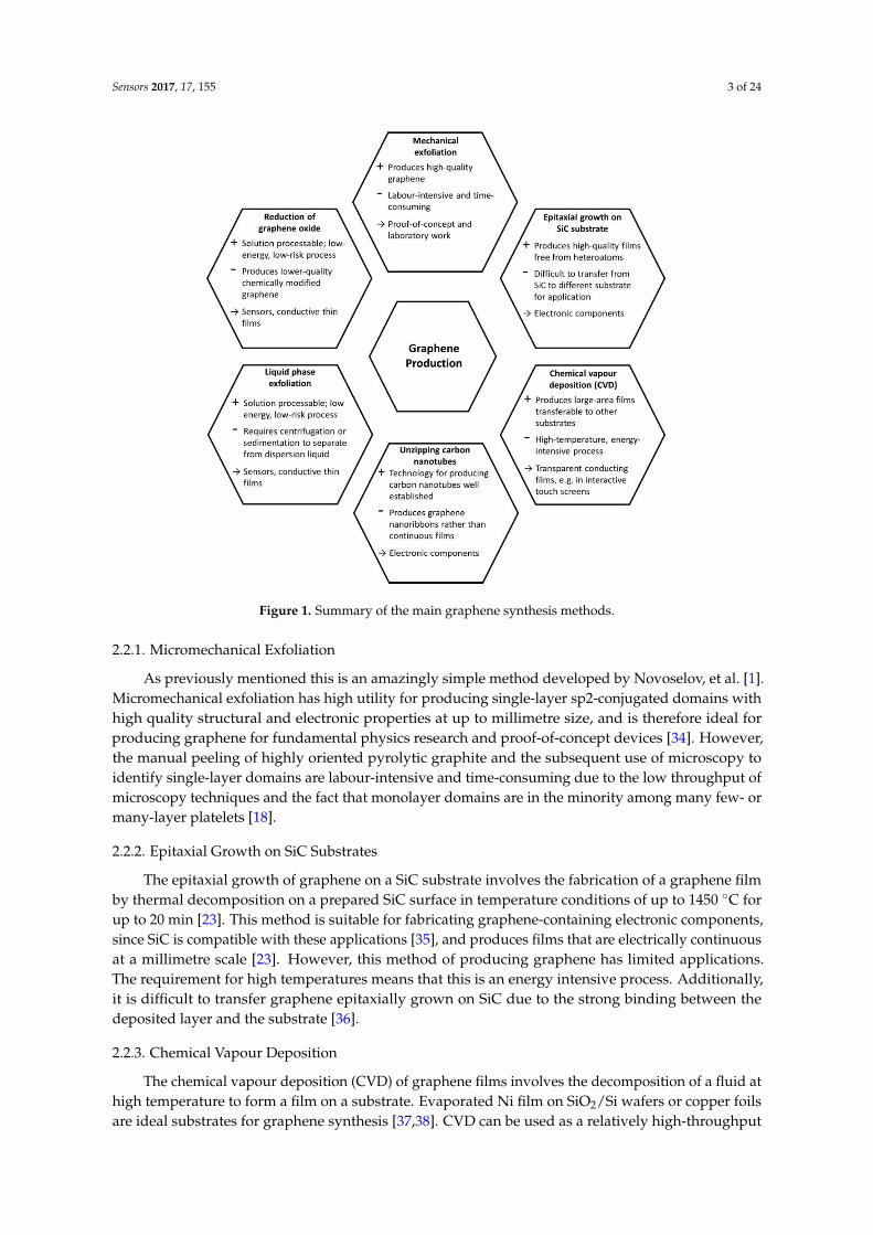
Different graphene production processes have been reported, which can be classified in differentcategories depending on the physical or chemical procedures employed. Figure 1 shows the mostcommon techniques for the production of graphene, which include micromechanical exfoliation(Scotch™ tape method) [1,18], epitaxial growth on SiC substrates [23,24], chemical vapour deposition(CVD) [25,26], unzipping carbon nanotubes [27,28], liquid phase exfoliation of graphite [29–31] andthermal & chemical reduction of exfoliated graphene oxide [22,32,33]. Each of these methods has itsown advantages as well as limitations depending on its target application.
Sensors 2017, 17, 155 3 of 24
Sensors 2017, 17, 155 3 of 23
Figure 1. Summary of the main graphene synthesis methods.
2.2.1. Micromechanical Exfoliation
As previously mentioned this is an amazingly simple method developed by Novoselov, et al.
[1]. Micromechanical exfoliation has high utility for producing single-layer sp2-conjugated domains
with high quality structural and electronic properties at up to millimetre size, and is therefore ideal
for producing graphene for fundamental physics research and proof-of-concept devices [34].
However, the manual peeling of highly oriented pyrolytic graphite and the subsequent use of
microscopy to identify single-layer domains are labour-intensive and time-consuming due to the low
throughput of microscopy techniques and the fact that monolayer domains are in the minority among
many few- or many-layer platelets [18].
2.2.2. Epitaxial Growth on SiC Substrates
The epitaxial growth of graphene on a SiC substrate involves the fabrication of a graphene film
by thermal decomposition on a prepared SiC surface in temperature conditions of up to 1450 °C for
up to 20 min [23]. This method is suitable for fabricating graphene-containing electronic components,
since SiC is compatible with these applications [35], and produces films that are electrically
continuous at a millimetre scale [23]. However, this method of producing graphene has limited
applications. The requirement for high temperatures means that this is an energy intensive process.
Additionally, it is difficult to transfer graphene epitaxially grown on SiC due to the strong binding
between the deposited layer and the substrate [36].
2.2.3. Chemical Vapour Deposition
The chemical vapour deposition (CVD) of graphene films involves the decomposition of a fluid
at high temperature to form a film on a substrate. Evaporated Ni film on SiO2/Si wafers or copper
foils are ideal substrates for graphene synthesis [37,38]. CVD can be used as a relatively high-
throughput production method [39] and it has been demonstrated that the deposited graphene film
Figure 1. Summary of the main graphene synthesis methods.
2.2.1. Micromechanical Exfoliation
As previously mentioned this is an amazingly simple method developed by Novoselov, et al. [1].Micromechanical exfoliation has high utility for producing single-layer sp2-conjugated domains withhigh quality structural and electronic properties at up to millimetre size, and is therefore ideal forproducing graphene for fundamental physics research and proof-of-concept devices [34]. However,the manual peeling of highly oriented pyrolytic graphite and the subsequent use of microscopy toidentify single-layer domains are labour-intensive and time-consuming due to the low throughput ofmicroscopy techniques and the fact that monolayer domains are in the minority among many few- ormany-layer platelets [18].
2.2.2. Epitaxial Growth on SiC Substrates
The epitaxial growth of graphene on a SiC substrate involves the fabrication of a graphene filmby thermal decomposition on a prepared SiC surface in temperature conditions of up to 1450 ◦C forup to 20 min [23]. This method is suitable for fabricating graphene-containing electronic components,since SiC is compatible with these applications [35], and produces films that are electrically continuousat a millimetre scale [23]. However, this method of producing graphene has limited applications.The requirement for high temperatures means that this is an energy intensive process. Additionally,it is difficult to transfer graphene epitaxially grown on SiC due to the strong binding between thedeposited layer and the substrate [36].
2.2.3. Chemical Vapour Deposition
The chemical vapour deposition (CVD) of graphene films involves the decomposition of a fluid athigh temperature to form a film on a substrate. Evaporated Ni film on SiO2/Si wafers or copper foilsare ideal substrates for graphene synthesis [37,38]. CVD can be used as a relatively high-throughput

Sensors 2017, 17, 155 4 of 24
production method [39] and it has been demonstrated that the deposited graphene film can betransferred from the original substrate to a wide range of other substrates [38,40]. Consequently, thisproduction method is potentially suitable for applications where a graphene film is required on aflexible or polymeric substrate that could not withstand high-temperature processing. The quality ofthe film deposited onto a substrate depends on the temperature: while achievable at temperatures aslow as 300 ◦C [41], higher temperatures are generally correlated with a more continuous crystallinestructure. Therefore, like epitaxial growth the need for high temperatures makes this an energyintensive process.
2.2.4. Unzipping of Carbon Nanotubes
It is possible to ‘unzip’ a one-dimensional carbon nanotube (CNT) (i.e., break a continuous lineof bonds along its length or in a helical pattern) to produce a two-dimensional graphene nanoribbon.The procedure for producing CNTs from graphite electrodes using the arc discharge method iswell established [42]. Various methods of unzipping single- and multi-walled CNTs (SWCNTs andMWCNTs respectively) have been reported, including: suspension first in concentrated sulphuricacid and then in potassium permanganate in mild conditions [27], argon plasma etching [43], andmechanical sonication in an organic solvent [44]. Although the unzipping of CNTs produces graphenenanoribbons approximately 10–20 nm in width rather than continuous sheets, it is possible to use theseribbons to produce arrays [43].
2.2.5. Liquid Phase Exfoliation of Graphite
The liquid-phase exfoliation of graphite involves the dispersion of graphite flakes in a solvent,ultrasonication of the dispersion to separate individual graphitic layers, and separation of single-layergraphene from remaining multi- and few-layer graphene and from the solvent. This final stage canbe achieved using centrifugation or sedimentation. Single-layer graphene can be identified usingmicroscopic and spectroscopic techniques [30,31]. In selecting a solvent, it is necessary to minimisethe interfacial tension between the graphite and the liquid in order to minimise the aggregationof single-layer graphene. Surfactants can be used to improve the dispersibility of graphene in thesolvent [31], however this may lead to the introduction of heteroatoms to the graphene plane. Althoughthe sonication process tends to produce small flakes with an area of at most 1 µm2 [45], these flakeshave high utility in solution processing [30].
2.2.6. Reduction of Exfoliated Graphene Oxide
Most of the previously mentioned synthesis methods are unsuitable for commercial-scalegraphene production. Fortunately, graphene oxide (GO) is a graphene precursor that can be easilyproduced at large scale by strong oxidation of graphite using acids via the Hummers’ method [46].This method enables the exfoliation of GO from bulk graphite at low temperature and in a short periodof time. It involves preparing a water-free mixture of powdered graphite, sodium nitrate, sulphuricacid and potassium permanganate, followed by filtration and centrifugation.
GO, an oxidized form of graphene, is decorated by hydroxyl and epoxy functional groups on thehexagonal network of carbon atoms with carbonyl and carboxyl groups at the edges [47,48]. In additionto being easier to produce than pristine graphene, the oxygen-containing functional groups of GOgive hydrophilicity, which can be very important for the large-scale uses of graphene as it enablesits dispersion into some solvents for film deposition [49]. However, the presence of oxygenatedfunctionalities in GO significantly diminishes its electrical conductivity compared to pristine graphenedue to the disruption to the conjugated π-electron system [50]. Consequently, for some applications itis essential to remove some oxygen-containing functional groups by means of reduction, in order topartially restore the valuable properties of graphene. The material derived from the reduction of GOis called partially reduced graphene oxide (rGO) or chemically converted graphene (CCG). Several

Sensors 2017, 17, 155 5 of 24
reduction methods have been reported [32,49,51–54]. They result in different properties of the obtainedrGO. The reduction rate will influence the performance of the final application.
• Thermal reduction of exfoliated graphene oxide
The thermal reduction is believed to be a green method because no hazardous reductants are used.GO can be reduced by thermal treatment and the process is named thermal annealing reduction.The key parameters in this reduction method are the annealing temperature and the annealingatmosphere. This process requires heating up to 1000 ◦C under vacuum [55] or inert atmosphere [56].Nevertheless, in hydrogen atmosphere the reduction can be carried out at much lower temperaturesdue to its high reduction ability [57,58].
Thermal annealing is an effective reduction method, however, due to the temperatures required,it is very energy intensive. In addition, some applications need the deposition of a GO thin film ona specific substrate, such as polymers, therefore this approach cannot be used to reduce GO filmsdeposited on substrates with low melting-points.
• Chemical reduction of exfoliated graphene oxide
Chemical reduction of GO involves its reaction with different chemical reducing agents.Hydrazine and its derivatives (hydrazine hydrate and dimethylhydrazine) have been acceptedas the best reducing agents [21,22,33,49]. The GO reduction is achieved by the addition of thereducing agent to the GO dispersion, obtaining agglomerated graphene-based nanosheets due to theincreased hydrophobicity.
A significant issue is the dangerousness of these reductants, being toxic, hazardous, explosive andnot environmentally benign. Consequently, continuous research has been focused on the developmentand optimization of eco-friendly reducing agents for GO reduction. Electron transfer reactionshave been demonstrated to partially reduce graphene oxide in reactions involving alcohols [59],vitamin C [60], and in high-pH solvents [61].
• Other reduction methods of exfoliated graphene oxide
A diverse range of alternative methods for the reduction of exfoliated graphene oxide havebeen proposed, including electrochemical and photolysis-based processes. The examples given arelow-temperature methods with minimal heteroatom contamination of the reduced graphene oxide.
The photolysis of graphene oxide by UV light, resulting in an order of magnitude improvementin conductivity, has been demonstrated to proceed quickly when catalysed by TiO2 or ZnO [62]. It hasalso been shown that UV photolysis can be used for the partial reduction of isolated solid grapheneoxide [63,64] and for graphene oxide in an aqueous suspension [65]. By contrast, the photolysisof graphene oxide films using lasers has been demonstrated using the relatively simple techniqueof depositing a graphene oxide film onto a DVD and using the laser of a DVD drive to produce afreestanding film with high conductivity (1738 Sm−1) [66].
Numerous methods have been developed to synthesise graphene, however high yield andcost-effective production of defect-free graphene at large-scale is not widely available, which is crucialfor real-world applications. The use of GO and rGO achieves a compromise between partial recoveryof the conjugated electron system, high scalability of production and suitability for solution processing,making them ideal candidates for commercial applications. Consequently, research efforts in the fieldof optical fibre sensors have mainly focused on the use of GO and rGO as sensing coatings.
3. Optical Fibre Sensors Using Graphene-Based Materials
3.1. Interferometry Based Optical Fibre Sensors Using Graphene-Based Coatings
Optical fibre interferometers use the interference between two beams that propagate throughdifferent optical paths (of a single fibre or different fibres). If one of the optical paths is affected
Sensors 2017, 17, 155 6 of 24
by external perturbations, the interference will be also affected. Interferometric signals give hugetemporal and spectral information. For this reason, the measurand can be quantitatively determinedthrough different properties of the optical signal such as wavelength, phase, intensity, frequency orbandwidth [67]. There are two main groups of optical fibre interferometers: Fabry-Perot (FPI) andMach-Zehnder (MZI).
MZIs have been widely used for optical fibre sensing applications due to their flexibleconfigurations. The early MZIs had two independent arms, the reference arm (isolated from externalvariations) and the sensing arm (exposed to the variations of the external medium). An incident lightis split into both arms by a fibre coupler and then recombined by another fibre coupler to obtain theinterference signal. The two-arm scheme was replaced by a more versatile in-line scheme. In thisnew generation of optical fibre MZIs a part of the beam guided through the core of an optical fibreis coupled to cladding modes of the same fibre by an intercalated element, and then re-coupled tothe core mode by another intercalated element. In these in-line MZIs both the reference arm andthe sensing arm have the same physical length. However, as the cladding mode beam has a lowereffective refractive index than the core mode beam they have different optical lengths due to themodal dispersion [67]. Different configurations of MZIs can be found depending on the couplingstrategy used, such as long period gratings, photonic crystal fibres, core mismatch, fibre tapering, etc.In Figure 2 schematic representation of an optical fibre MZI can be found.
Sensors 2017, 17, 155 6 of 23
bandwidth [67]. There are two main groups of optical fibre interferometers: Fabry-Perot (FPI) and
Mach-Zehnder (MZI).
MZIs have been widely used for optical fibre sensing applications due to their flexible
configurations. The early MZIs had two independent arms, the reference arm (isolated from external
variations) and the sensing arm (exposed to the variations of the external medium). An incident light
is split into both arms by a fibre coupler and then recombined by another fibre coupler to obtain the
interference signal. The two-arm scheme was replaced by a more versatile in-line scheme. In this new
generation of optical fibre MZIs a part of the beam guided through the core of an optical fibre is
coupled to cladding modes of the same fibre by an intercalated element, and then re-coupled to the
core mode by another intercalated element. In these in-line MZIs both the reference arm and the
sensing arm have the same physical length. However, as the cladding mode beam has a lower
effective refractive index than the core mode beam they have different optical lengths due to the
modal dispersion [67]. Different configurations of MZIs can be found depending on the coupling
strategy used, such as long period gratings, photonic crystal fibres, core mismatch, fibre tapering, etc.
In Figure 2a schematic representation of an optical fibre MZI can be found.
Figure 2. Schematic representation of a MZI-optical fibre sensor.
Some authors have used graphene-based materials in MZI configurations to obtain optical fibre
sensors. Yao et al. [68], report an ammonia sensor based on a graphene/microfibre hybrid waveguide.
The sensing mechanism relies on the modification of the graphene conductivity because of the
adsorption of ammonia. Consequently, the effective refractive index of the device and the light
transmitted along it are very sensitive to ammonia concentration. A sensitivity of ~6 pm/ppm was
obtained using this approach.
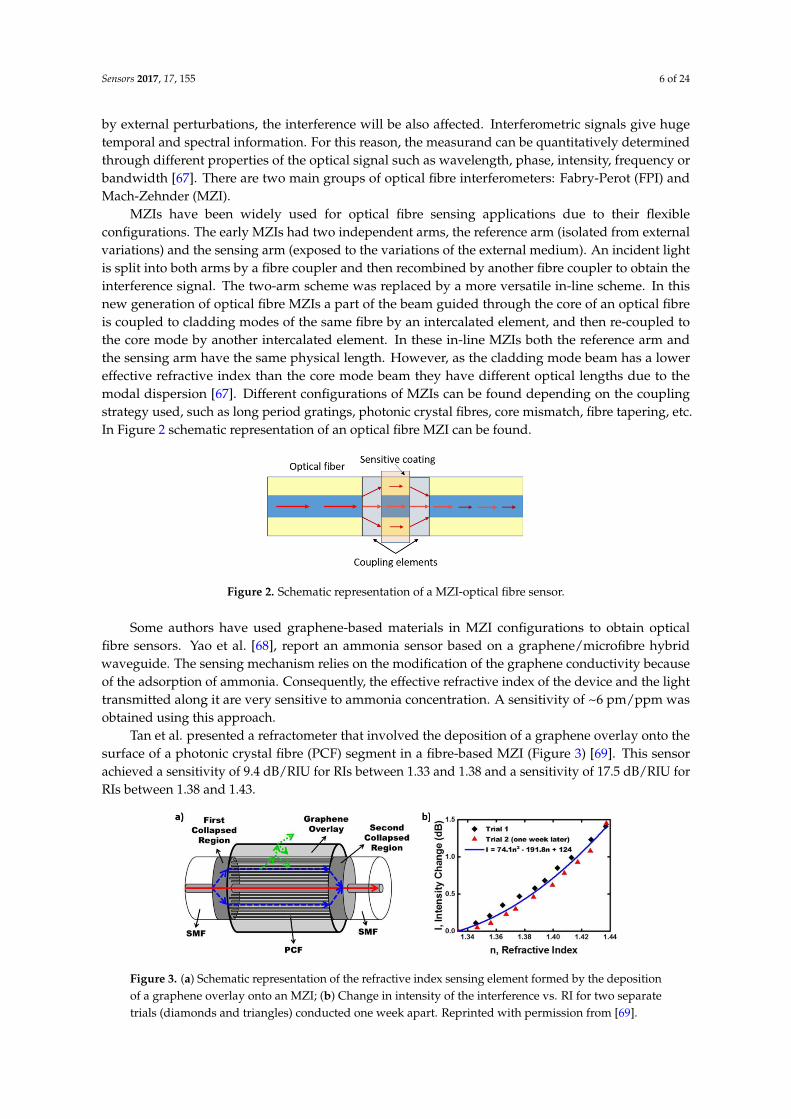
Tan et al. presented a refractometer that involved the deposition of a graphene overlay onto the
surface of a photonic crystal fibre (PCF) segment in a fibre-based MZI (Figure 3) [69]. This sensor
achieved a sensitivity of 9.4 dB/RIU for RIs between 1.33 and 1.38 and a sensitivity of 17.5 dB/RIU for
RIs between 1.38 and 1.43.
Figure 3. (a) Schematic representation of the refractive index sensing element formed by the
deposition of a graphene overlay onto an MZI; (b) Change in intensity of the interference vs. RI for
two separate trials (diamonds and triangles) conducted one week apart. Reprinted with permission
from [69].
Figure 2. Schematic representation of a MZI-optical fibre sensor.
Some authors have used graphene-based materials in MZI configurations to obtain opticalfibre sensors. Yao et al. [68], report an ammonia sensor based on a graphene/microfibre hybridwaveguide. The sensing mechanism relies on the modification of the graphene conductivity becauseof the adsorption of ammonia. Consequently, the effective refractive index of the device and the lighttransmitted along it are very sensitive to ammonia concentration. A sensitivity of ~6 pm/ppm wasobtained using this approach.
Tan et al. presented a refractometer that involved the deposition of a graphene overlay onto thesurface of a photonic crystal fibre (PCF) segment in a fibre-based MZI (Figure 3) [69]. This sensorachieved a sensitivity of 9.4 dB/RIU for RIs between 1.33 and 1.38 and a sensitivity of 17.5 dB/RIU forRIs between 1.38 and 1.43.
Sensors 2017, 17, 155 6 of 23
bandwidth [67]. There are two main groups of optical fibre interferometers: Fabry-Perot (FPI) and
Mach-Zehnder (MZI).
MZIs have been widely used for optical fibre sensing applications due to their flexible
configurations. The early MZIs had two independent arms, the reference arm (isolated from external
variations) and the sensing arm (exposed to the variations of the external medium). An incident light
is split into both arms by a fibre coupler and then recombined by another fibre coupler to obtain the
interference signal. The two-arm scheme was replaced by a more versatile in-line scheme. In this new
generation of optical fibre MZIs a part of the beam guided through the core of an optical fibre is
coupled to cladding modes of the same fibre by an intercalated element, and then re-coupled to the
core mode by another intercalated element. In these in-line MZIs both the reference arm and the
sensing arm have the same physical length. However, as the cladding mode beam has a lower
effective refractive index than the core mode beam they have different optical lengths due to the
modal dispersion [67]. Different configurations of MZIs can be found depending on the coupling
strategy used, such as long period gratings, photonic crystal fibres, core mismatch, fibre tapering, etc.
In Figure 2a schematic representation of an optical fibre MZI can be found.
Figure 2. Schematic representation of a MZI-optical fibre sensor.
Some authors have used graphene-based materials in MZI configurations to obtain optical fibre
sensors. Yao et al. [68], report an ammonia sensor based on a graphene/microfibre hybrid waveguide.
The sensing mechanism relies on the modification of the graphene conductivity because of the
adsorption of ammonia. Consequently, the effective refractive index of the device and the light
transmitted along it are very sensitive to ammonia concentration. A sensitivity of ~6 pm/ppm was
obtained using this approach.
Tan et al. presented a refractometer that involved the deposition of a graphene overlay onto the
surface of a photonic crystal fibre (PCF) segment in a fibre-based MZI (Figure 3) [69]. This sensor
achieved a sensitivity of 9.4 dB/RIU for RIs between 1.33 and 1.38 and a sensitivity of 17.5 dB/RIU for
RIs between 1.38 and 1.43.
Figure 3. (a) Schematic representation of the refractive index sensing element formed by the
deposition of a graphene overlay onto an MZI; (b) Change in intensity of the interference vs. RI for
two separate trials (diamonds and triangles) conducted one week apart. Reprinted with permission
from [69].
Figure 3. (a) Schematic representation of the refractive index sensing element formed by the depositionof a graphene overlay onto an MZI; (b) Change in intensity of the interference vs. RI for two separatetrials (diamonds and triangles) conducted one week apart. Reprinted with permission from [69].

Sensors 2017, 17, 155 7 of 24
A similar device using GO as sensitive coating has been recently reported by Dash et al. [70].When the RI of the analyte is changed from 1.3310 to 1.3715, the wavelength of the dip shifts from1544.4 nm to 1553 nm (wavelength sensitivity of 212 nm/RIU) and the intensity of the dip also changesfrom −78.16 to −83.43 dBm (intensity sensitivity of 130 dB/RIU). This sensitivity is higher than thepreviously reported results based on similar configurations without any coating [71,72].
An FPI consists of two parallel optical mirrors separated by a certain distance. Interference occursdue to the multiple additions of reflected and transmitted beams at the two mirrors. In the case ofoptical fibres, FPI sensors can be classified into extrinsic and intrinsic. Extrinsic FPIs use the reflectionsfrom an external cavity formed outside the fibre, as shown in Figure 4. This cavity can be built usingan air space and a diaphragm or a coating made of a sensitive material. Intrinsic FPIs sensors havereflecting components within the fibre itself [67].
Sensors 2017, 17, 155 7 of 23
A similar device using GO as sensitive coating has been recently reported by Dash et al. [70].
When the RI of the analyte is changed from 1.3310 to 1.3715, the wavelength of the dip shifts from
1544.4 nm to 1553 nm (wavelength sensitivity of 212 nm/RIU) and the intensity of the dip also changes
from −78.16 to −83.43 dBm (intensity sensitivity of 130 dB/RIU). This sensitivity is higher than the
previously reported results based on similar configurations without any coating [71,72].
An FPI consists of two parallel optical mirrors separated by a certain distance. Interference
occurs due to the multiple additions of reflected and transmitted beams at the two mirrors. In the
case of optical fibres, FPI sensors can be classified into extrinsic and intrinsic. Extrinsic FPIs use the
reflections from an external cavity formed outside the fibre, as shown in Figure 4. This cavity can be
built using an air space and a diaphragm or a coating made of a sensitive material. Intrinsic FPIs
sensors have reflecting components within the fibre itself [67].
Figure 4. Schematic representation of an extrinsic Fabry-Perot interferometer on the tip of an optical fibre.
Li and co-workers from Beihang University (China) have developed in the last few years a wide
variety of sensors based on FPI using a G diaphragm. Figure 5a shows the schematic diagram of these
FPI sensors which include a zirconia ferrule, a standard single mode fibre (SMF) and a multi-layer
graphene diaphragm. The diaphragm, adhered to the zirconia substrate by van der Waals forces, acts
as a light reflector. When this device was tested as a temperature sensor [73], the variation of the
cavity length was approximately 352 nm/°C in the temperature range from 20 °C to 60 °C. This effect
is induced by the thermal deformation of the graphene diaphragm. However, the intensity and phase
shifts at common temperatures featured a periodic appearance even due to a narrow thermal
fluctuation (Figure 5b). This group has used similar devices to develop sensors for pressure [74],
adhesion energy [75] and thermal expansion coefficient [76] of graphene. A similar approach was
used in [77] to obtain an optical fibre acetylene detector with low level detection of acetylene and a
lower detection limit of 119.8 ppb.
Figure 5. (a) Schematic diagram of the FP sensor; (b) Reflection spectra of the FP sensor for different
temperatures. Reprinted with permission from [73].
Figure 4. Schematic representation of an extrinsic Fabry-Perot interferometer on the tip of anoptical fibre.
Li and co-workers from Beihang University (China) have developed in the last few years a widevariety of sensors based on FPI using a G diaphragm. Figure 5a shows the schematic diagram of theseFPI sensors which include a zirconia ferrule, a standard single mode fibre (SMF) and a multi-layergraphene diaphragm. The diaphragm, adhered to the zirconia substrate by van der Waals forces, actsas a light reflector. When this device was tested as a temperature sensor [73], the variation of thecavity length was approximately 352 nm/◦C in the temperature range from 20 ◦C to 60 ◦C. This effectis induced by the thermal deformation of the graphene diaphragm. However, the intensity andphase shifts at common temperatures featured a periodic appearance even due to a narrow thermalfluctuation (Figure 5b). This group has used similar devices to develop sensors for pressure [74],adhesion energy [75] and thermal expansion coefficient [76] of graphene. A similar approach was usedin [77] to obtain an optical fibre acetylene detector with low level detection of acetylene and a lowerdetection limit of 119.8 ppb.
Sensors 2017, 17, 155 7 of 23
A similar device using GO as sensitive coating has been recently reported by Dash et al. [70].
When the RI of the analyte is changed from 1.3310 to 1.3715, the wavelength of the dip shifts from
1544.4 nm to 1553 nm (wavelength sensitivity of 212 nm/RIU) and the intensity of the dip also changes
from −78.16 to −83.43 dBm (intensity sensitivity of 130 dB/RIU). This sensitivity is higher than the
previously reported results based on similar configurations without any coating [71,72].
An FPI consists of two parallel optical mirrors separated by a certain distance. Interference
occurs due to the multiple additions of reflected and transmitted beams at the two mirrors. In the
case of optical fibres, FPI sensors can be classified into extrinsic and intrinsic. Extrinsic FPIs use the
reflections from an external cavity formed outside the fibre, as shown in Figure 4. This cavity can be
built using an air space and a diaphragm or a coating made of a sensitive material. Intrinsic FPIs
sensors have reflecting components within the fibre itself [67].
Figure 4. Schematic representation of an extrinsic Fabry-Perot interferometer on the tip of an optical fibre.
Li and co-workers from Beihang University (China) have developed in the last few years a wide
variety of sensors based on FPI using a G diaphragm. Figure 5a shows the schematic diagram of these
FPI sensors which include a zirconia ferrule, a standard single mode fibre (SMF) and a multi-layer
graphene diaphragm. The diaphragm, adhered to the zirconia substrate by van der Waals forces, acts
as a light reflector. When this device was tested as a temperature sensor [73], the variation of the
cavity length was approximately 352 nm/°C in the temperature range from 20 °C to 60 °C. This effect
is induced by the thermal deformation of the graphene diaphragm. However, the intensity and phase
shifts at common temperatures featured a periodic appearance even due to a narrow thermal
fluctuation (Figure 5b). This group has used similar devices to develop sensors for pressure [74],
adhesion energy [75] and thermal expansion coefficient [76] of graphene. A similar approach was
used in [77] to obtain an optical fibre acetylene detector with low level detection of acetylene and a
lower detection limit of 119.8 ppb.
Figure 5. (a) Schematic diagram of the FP sensor; (b) Reflection spectra of the FP sensor for different
temperatures. Reprinted with permission from [73].
Figure 5. (a) Schematic diagram of the FP sensor; (b) Reflection spectra of the FP sensor for differenttemperatures. Reprinted with permission from [73].

Sensors 2017, 17, 155 8 of 24
3.2. Surface Plasmon Resonance Optical Fibre Sensors Using Graphene-Based Coatings
Over the past two decades, surface plasmon resonance (SPR) based sensors have attracted theattention of many researchers due to their potential applications in the field of physical, chemicaland biomedical sciences [78–84]. A surface plasmon is a transverse magnetic (TM) polarizedelectromagnetic wave excited by p-polarized light. Due to the exponential decay of the plasmonelectric field, it is strongly localized at the metal-dielectric interface. When a plasmon is excited, anabsorption peak (SPR) at a determined wavelength (resonance wavelength, λSPR) is produced [79].
In the case of optical fibre-based SPR sensors, the device shown in Figure 6 is typically used toexcite a surface plasmon. The cladding from a small portion of the fibre is removed and this uncladportion is coated with a thin layer of metal. The light from a polychromatic source is coupled into thefibre from one end and the spectrum of the transmitted power at the other end is collected. Due to theSPR, a peak at λSPR is obtained in the transmitted spectrum. This λSPR shows a strong dependence onthe refractive index of the sensing medium around the metal layer. Using this scheme, a great varietyof sensors can be obtained just by depositing onto the metal thin-film a material that is sensitive to thechemical compound or physical property of interest [85,86].
Sensors 2017, 17, 155 8 of 23
3.2. Surface Plasmon Resonance Optical Fibre Sensors Using Graphene-Based Coatings
Over the past two decades, surface plasmon resonance (SPR) based sensors have attracted the
attention of many researchers due to their potential applications in the field of physical, chemical and
biomedical sciences [78–84]. A surface plasmon is a transverse magnetic (TM) polarized
electromagnetic wave excited by p-polarized light. Due to the exponential decay of the plasmon
electric field, it is strongly localized at the metal-dielectric interface. When a plasmon is excited, an
absorption peak (SPR) at a determined wavelength (resonance wavelength, λSPR) is produced [79].
In the case of optical fibre-based SPR sensors, the device shown in Figure 6 is typically used to
excite a surface plasmon. The cladding from a small portion of the fibre is removed and this unclad
portion is coated with a thin layer of metal. The light from a polychromatic source is coupled into the
fibre from one end and the spectrum of the transmitted power at the other end is collected. Due to
the SPR, a peak at λSPR is obtained in the transmitted spectrum. This λSPR shows a strong dependence
on the refractive index of the sensing medium around the metal layer. Using this scheme, a great
variety of sensors can be obtained just by depositing onto the metal thin-film a material that is
sensitive to the chemical compound or physical property of interest [85,86].
Figure 6. Schematic representation of a SPR-based optical fibre sensor.
In the last few years, some studies that include graphene materials in optical fibre SPR-based
sensors have been published. In these studies, graphene materials can play different roles. Some
authors have used them as SPR supporting materials instead of the typically used gold and silver
layers or in addition to them. In other cases, the authors have utilized graphene-based coatings as the
sensitive material, which reacts to any variation of the target analyte. In the next paragraphs, some
examples of these sensors are introduced.
Kim et al. used graphene in a SPR sensor as replacement material for gold or silver [87,88]. A
multi-layered graphene film was synthesized by (CVD) on a Ni substrate and transferred on the
sensing region of an optical fibre. The graphene coated SPR sensor showed a good sensitivity when
used to analyse the interaction between structured DNA biotin and Streptavidin.
In [89], the authors presented a theoretical study of an SPR biosensor for detection of bonding
between adenine and thymine or between guanine and cytosine (DNA hybridization). They selected
gold as SPR-generating layer and introduced a multilayer graphene structure on its surface. The
proposed sensor seemed to be more sensitive than conventional biosensors without the graphene
layer. Additionally, the sensitivity linearly increased with the increase in the number of graphene
layers. In particular, an improvement of 25% in the sensitivity was achieved by adding 10 G layers to
the conventional gold thin film SPR biosensor. This improvement is mainly due to the better
adsorption of DNA molecules on G than on gold. Fu et al. [90] proposed a similar approach to
demonstrate theoretically the enhancement in sensitivity of a SPR refractive index sensor with G
layers onto a gold SPR-supporting layer.
In [91], the authors simulated the performance of a photonic crystal fibre (PCF) SPR-based
refractive index sensor. A silver layer deposited onto the inner surface of one of the PCF holes acted
as SPR supporting layer and a G layer deposited onto the silver coating was used to inhibit its
oxidation (see sensor cross section in Figure 7a). The analyte, a liquid with high RI, was infiltrated
into the deposited channel hole and the fibre cores. The proposed sensor showed a maximum RI
sensitivity of 3000 nm/RIU and an average RI sensitivity of 2390 nm/RIU in the sensing range of 1.46
to 1.49 (see Figure 7b). This sensitivity is slightly lower than the achieved by other works using a
similar structure with a single gold layer [92].
Figure 6. Schematic representation of a SPR-based optical fibre sensor.
In the last few years, some studies that include graphene materials in optical fibre SPR-basedsensors have been published. In these studies, graphene materials can play different roles. Someauthors have used them as SPR supporting materials instead of the typically used gold and silverlayers or in addition to them. In other cases, the authors have utilized graphene-based coatings as thesensitive material, which reacts to any variation of the target analyte. In the next paragraphs, someexamples of these sensors are introduced.
Kim et al. used graphene in a SPR sensor as replacement material for gold or silver [87,88].A multi-layered graphene film was synthesized by (CVD) on a Ni substrate and transferred on thesensing region of an optical fibre. The graphene coated SPR sensor showed a good sensitivity whenused to analyse the interaction between structured DNA biotin and Streptavidin.
In [89], the authors presented a theoretical study of an SPR biosensor for detection of bondingbetween adenine and thymine or between guanine and cytosine (DNA hybridization). They selectedgold as SPR-generating layer and introduced a multilayer graphene structure on its surface.The proposed sensor seemed to be more sensitive than conventional biosensors without the graphenelayer. Additionally, the sensitivity linearly increased with the increase in the number of graphenelayers. In particular, an improvement of 25% in the sensitivity was achieved by adding 10 G layers tothe conventional gold thin film SPR biosensor. This improvement is mainly due to the better adsorptionof DNA molecules on G than on gold. Fu et al. [90] proposed a similar approach to demonstratetheoretically the enhancement in sensitivity of a SPR refractive index sensor with G layers onto a goldSPR-supporting layer.
In [91], the authors simulated the performance of a photonic crystal fibre (PCF) SPR-basedrefractive index sensor. A silver layer deposited onto the inner surface of one of the PCF holes acted asSPR supporting layer and a G layer deposited onto the silver coating was used to inhibit its oxidation(see sensor cross section in Figure 7a). The analyte, a liquid with high RI, was infiltrated into thedeposited channel hole and the fibre cores. The proposed sensor showed a maximum RI sensitivity

Sensors 2017, 17, 155 9 of 24
of 3000 nm/RIU and an average RI sensitivity of 2390 nm/RIU in the sensing range of 1.46 to 1.49(see Figure 7b). This sensitivity is slightly lower than the achieved by other works using a similarstructure with a single gold layer [92].Sensors 2017, 17, 155 9 of 23
Figure 7. (a) Cross-section of the SPR-based sensor proposed in [91]. (b) Loss spectrum of the
fundamental mode by increasing analyte RI from 1.46 to 1.49. Published under a Creative Commons
Attribution License (CC-BY).
Mishra and co-authors carried out a detailed study about the fabrication and characterization of
SPR-based fibre optic gas sensors using rGO, carbon nanotubes (CNTs) and poly(methyl
methacrylate) (PMMA) [93]. Probes with a silver SPR-supporting layer were coated with different
sensitive materials (rGO, CNTs, rGO-CNTs and rGO/CNT/PMMA hybrid nanocomposite) in order
to achieve the best performance sensor for the detection of several gases (methane, ammonia,
hydrogen sulphide, chlorine, carbon dioxide, hydrogen, and nitrogen). Among all the tested
possibilities, the sensor based on rGO/CNT/PMMA hybrid nanocomposite showed a high selectivity
to methane. The sensitivity of this device was optimized by varying the concentration of rGO/CNT
in PMMA. The optimum doping concentration was 5 wt. % and the maximum sensitivity was 0.33
nm/ppm in the range for methane gas concentrations from 10 to 100 ppm. The same group developed
an ammonia sensor based on SPR using a copper supporting layer and rGO/PMMA hybrid
composite, obtaining a maximum sensitivity close to 1 nm/ppm in the same range of ammonia
concentration [94].
A particular case of SPR is localized surface plasmon resonance (LSPR). When a very thin
dielectric coating that includes metal nanoparticles (typically gold or silver) is deposited onto a
waveguide, a resonant coupling between the incident electromagnetic wave and the surface of the
thin-film is produced. This results in an electromagnetic wave at the metal-dielectric interface that
causes appearance of a sharp absorption peak at a determined wavelength in the transmitted
spectrum [95,96].
Nayak et al. developed different refractive index sensors using graphene oxide encapsulated
gold nanoparticles (GOE-AuNPs) [97] and graphene oxide-encapsulated silver nanoparticles (GOE-
AgNPs) [98] as LSPR generating materials. The main benefits of encapsulating the nanoparticles in
GO are the control of the inter-particle distance, preventing aggregation, the enhancement of the
colloidal stability and the prevention of the oxidation of the AgNPs, avoiding their direct contact with
the aqueous medium. The variation in the absorbance of the LSPR peak when the device was
immersed in aqueous solutions with refractive indices between 1.34 and 1.38 produced sensitivities
of 2.288 ΔA/RIU and 0.9406 ΔA/RIU for GOE-Au NPs and GOE-AgNPs, respectively.
3.3. Fibre Bragg Gratings Sensors Using Graphene-Based Coatings
Fibre gratings consist of a periodic perturbation of the properties of the optical fibre, generally
of the refractive index of the core (Figure 8). In Fibre Bragg gratings (FBGs), this alteration produces
a coupling of light from the forward-propagating mode of the optical fibre to a backward propagating
mode. This coupling occurs at a specific wavelength that depends on the period of the FBG and the
effective index of the propagating mode. As a consequence, a variation in either of these parameters
produce a change in the coupling wavelength (Bragg wavelength, λB) that can be measured. As strain
and temperature have a direct influence on the mentioned parameters, many sensing schemes based
on FBGs have been developed to measure these signals [99–107].
Figure 7. (a) Cross-section of the SPR-based sensor proposed in [91]. (b) Loss spectrum of thefundamental mode by increasing analyte RI from 1.46 to 1.49. Published under a Creative CommonsAttribution License (CC-BY).
Mishra and co-authors carried out a detailed study about the fabrication and characterization ofSPR-based fibre optic gas sensors using rGO, carbon nanotubes (CNTs) and poly(methyl methacrylate)(PMMA) [93]. Probes with a silver SPR-supporting layer were coated with different sensitive materials(rGO, CNTs, rGO-CNTs and rGO/CNT/PMMA hybrid nanocomposite) in order to achieve thebest performance sensor for the detection of several gases (methane, ammonia, hydrogen sulphide,chlorine, carbon dioxide, hydrogen, and nitrogen). Among all the tested possibilities, the sensor basedon rGO/CNT/PMMA hybrid nanocomposite showed a high selectivity to methane. The sensitivity ofthis device was optimized by varying the concentration of rGO/CNT in PMMA. The optimum dopingconcentration was 5 wt. % and the maximum sensitivity was 0.33 nm/ppm in the range for methanegas concentrations from 10 to 100 ppm. The same group developed an ammonia sensor based on SPRusing a copper supporting layer and rGO/PMMA hybrid composite, obtaining a maximum sensitivityclose to 1 nm/ppm in the same range of ammonia concentration [94].
A particular case of SPR is localized surface plasmon resonance (LSPR). When a very thin dielectriccoating that includes metal nanoparticles (typically gold or silver) is deposited onto a waveguide,a resonant coupling between the incident electromagnetic wave and the surface of the thin-filmis produced. This results in an electromagnetic wave at the metal-dielectric interface that causesappearance of a sharp absorption peak at a determined wavelength in the transmitted spectrum [95,96].
Nayak et al. developed different refractive index sensors using graphene oxide encapsulatedgold nanoparticles (GOE-AuNPs) [97] and graphene oxide-encapsulated silver nanoparticles(GOE-AgNPs) [98] as LSPR generating materials. The main benefits of encapsulating the nanoparticlesin GO are the control of the inter-particle distance, preventing aggregation, the enhancement of thecolloidal stability and the prevention of the oxidation of the AgNPs, avoiding their direct contactwith the aqueous medium. The variation in the absorbance of the LSPR peak when the device wasimmersed in aqueous solutions with refractive indices between 1.34 and 1.38 produced sensitivities of2.288 ∆A/RIU and 0.9406 ∆A/RIU for GOE-Au NPs and GOE-AgNPs, respectively.
3.3. Fibre Bragg Gratings Sensors Using Graphene-Based Coatings
Fibre gratings consist of a periodic perturbation of the properties of the optical fibre, generally ofthe refractive index of the core (Figure 8). In Fibre Bragg gratings (FBGs), this alteration produces acoupling of light from the forward-propagating mode of the optical fibre to a backward propagatingmode. This coupling occurs at a specific wavelength that depends on the period of the FBG and theeffective index of the propagating mode. As a consequence, a variation in either of these parameters

Sensors 2017, 17, 155 10 of 24
produce a change in the coupling wavelength (Bragg wavelength, λB) that can be measured. As strainand temperature have a direct influence on the mentioned parameters, many sensing schemes basedon FBGs have been developed to measure these signals [99–107].
Sensors 2017, 17, 155 10 of 23
FBGs can be also used for chemical sensing and biosensing. For this purpose, FBGs are coated
with a material whose structure varies in the presence of a particular chemical compound (analyte).
When the concentration of this analyte changes, the deformation of the coating produces an axial
strain. The FBG stretches or shrinks under such strain and therefore the spectral pattern of reflected
light changes, producing a shift in reflected wavelength [108]. If the fibre core of the FBGs is covered
by the cladding layer, it is less sensitive to the variations in the surrounding medium. To overcome
this issue, the cladding is etched in order to expose the propagating modes of the core to the
surrounding medium [109]. A schematic representation of an etched FBG (eFBG) coated with a
sensitive thin-film is shown in Figure 8. These devices have been used for chemical applications such
as refractive index sensing [106], gas sensors [108] or relative humidity sensors [110] and also for
biosensing applications [109,111,112].
Figure 8. Schematic representation of an eFBG coated with a sensitive thin film.
In the last few years, an increasing number of studies about optical fibre sensors based on FBGs
have been focused on devices that include coatings made of graphene-based materials. In this section,
different examples of these structures are presented.
The Sood group from the Indian Institute of Science (Bangalore, India) has intensively studied
this type of sensor. They have developed different sensing schemes based on etched FBGs including
gas detectors, physical sensors and biosensors. In particular, they have enhanced the typical
sensitivity of bare FBGs to strain and temperature by coating with rGO an etched FBG. These sensors
showed a sensitivity to strain of 5.5 pm/με and a sensitivity to temperature of 33 pm/°C (5 and 3 times
better than bare FBGs). The resolutions obtained with these sensors were about 1 με for strain
measurements and 0.3 °C for temperature measurements [113].
Furthermore, the same group has developed different biosensors based on this configuration. In
[109], they presented an etched FBG coated with aminophenylboronic acid (APBA)-functionalized
rGO that exhibited high sensitivity to glucose. These sensors showed a linear shift in Bragg
wavelength with the concentration of a glucose solution in the range of 1 nM to 10 mM, covering the
clinical range of the estimated average glucose concentration in red blood cells, which enables them
to be used in detection of diabetes. They have also designed and characterized biosensors for proteins
CRP [111] and concanavalin A [114] detection using this sensing scheme.
Other research groups have also exploited the mentioned mechanism. Wang et al. have recently
developed a relative humidity sensor consisting of a tilted FBG coated with a GO thin film obtaining
a maximum sensitivity of 0.129 dB/%RH in the relative humidity range from 10% to 80% [115].
Zhang et al. studied the features of a graphene-coated microfibre FBG (GMFBG) as an ammonia
sensor. Figure 9 shows the experimental setup used in this study [116]. Different diameters of
GMFBGs were tested for NH3 gas with the concentrations of 0 ppm, ~10 ppm, ~50 ppm, and ~100
ppm. To further demonstrate the enhancement effect by graphene, bare microfibre FBGs (MFBGs)
with different diameters were also tested. The results of these experiments are shown in Figure 10. It
can be concluded that MFBGs without the graphene cladding were almost not sensitive to gas
adsorption while GMFBGs showed a maximum sensitivity of 6 pm/ppm for 10 µm diameter
microfibres. These results also indicate that the GMFBG with a smaller diameter were more sensitive
to the gas concentration alteration.
Figure 8. Schematic representation of an eFBG coated with a sensitive thin film.
FBGs can be also used for chemical sensing and biosensing. For this purpose, FBGs are coatedwith a material whose structure varies in the presence of a particular chemical compound (analyte).When the concentration of this analyte changes, the deformation of the coating produces an axial strain.The FBG stretches or shrinks under such strain and therefore the spectral pattern of reflected lightchanges, producing a shift in reflected wavelength [108]. If the fibre core of the FBGs is covered bythe cladding layer, it is less sensitive to the variations in the surrounding medium. To overcome thisissue, the cladding is etched in order to expose the propagating modes of the core to the surroundingmedium [109]. A schematic representation of an etched FBG (eFBG) coated with a sensitive thin-filmis shown in Figure 8. These devices have been used for chemical applications such as refractiveindex sensing [106], gas sensors [108] or relative humidity sensors [110] and also for biosensingapplications [109,111,112].
In the last few years, an increasing number of studies about optical fibre sensors based on FBGshave been focused on devices that include coatings made of graphene-based materials. In this section,different examples of these structures are presented.
The Sood group from the Indian Institute of Science (Bangalore, India) has intensively studiedthis type of sensor. They have developed different sensing schemes based on etched FBGs includinggas detectors, physical sensors and biosensors. In particular, they have enhanced the typical sensitivityof bare FBGs to strain and temperature by coating with rGO an etched FBG. These sensors showed asensitivity to strain of 5.5 pm/µε and a sensitivity to temperature of 33 pm/◦C (5 and 3 times betterthan bare FBGs). The resolutions obtained with these sensors were about 1 µε for strain measurementsand 0.3 ◦C for temperature measurements [113].
Furthermore, the same group has developed different biosensors based on this configuration.In [109], they presented an etched FBG coated with aminophenylboronic acid (APBA)-functionalizedrGO that exhibited high sensitivity to glucose. These sensors showed a linear shift in Bragg wavelengthwith the concentration of a glucose solution in the range of 1 nM to 10 mM, covering the clinical rangeof the estimated average glucose concentration in red blood cells, which enables them to be used indetection of diabetes. They have also designed and characterized biosensors for proteins CRP [111]and concanavalin A [114] detection using this sensing scheme.
Other research groups have also exploited the mentioned mechanism. Wang et al. have recentlydeveloped a relative humidity sensor consisting of a tilted FBG coated with a GO thin film obtaining amaximum sensitivity of 0.129 dB/%RH in the relative humidity range from 10% to 80% [115].
Zhang et al. studied the features of a graphene-coated microfibre FBG (GMFBG) as an ammoniasensor. Figure 9 shows the experimental setup used in this study [116]. Different diameters ofGMFBGs were tested for NH3 gas with the concentrations of 0 ppm, ~10 ppm, ~50 ppm, and~100 ppm. To further demonstrate the enhancement effect by graphene, bare microfibre FBGs(MFBGs) with different diameters were also tested. The results of these experiments are shownin Figure 10. It can be concluded that MFBGs without the graphene cladding were almost not sensitiveto gas adsorption while GMFBGs showed a maximum sensitivity of 6 pm/ppm for 10 µm diameter

Sensors 2017, 17, 155 11 of 24
microfibres. These results also indicate that the GMFBG with a smaller diameter were more sensitiveto the gas concentration alteration.Sensors 2017, 17, 155 11 of 23
Figure 9. Schematic representation of the experimental setup used in the characterization of an
ammonia sensor consisting of a graphene-coated eFBG. Reprinted with permission from [116].
Figure 10. Spectral shifts of the GMFBGs and MFBGs for different concentrations of NH3. Reprinted
with permission from [116].
3.4. Absorption-Based Optical Fibre Sensors Using Graphene-Based Coatings
FBGs/LPGs and optical fibre interferometers require complex fibre optic pre-processing or
sophisticated control at the micrometre level respectively. In contrast, optical fibre sensors based on
light intensity monitoring, such as transmission, absorption or reflection, are relatively simple to
implement. On the other hand, these systems are vulnerable to light intensity variations, light source
instabilities, micro and macro bending or external source coupling. In order to overcome these
undesired effects these systems use complex detection algorithms and systems with referenced
measurements, which are not associated with the light intensity variations produced by the selected
analyte [117,118].
Absorption-based optical fibre sensors rely on the fact that the selected target or transducer must
modify the intensity of the light propagated through the optical fibre core as a function of the selected
measurand. Here, the intensity loss can be described using the Beer-Lambert law:
I1 = I0e−αl (1)
where l is the length of the fibre sensitive region, I0 and I1 are the excitation and transmitted light
intensities and α, the absorption coefficient, can be expressed as α = Cε/loge where C is the molar
concentration and ε is the molar absorptivity. The absorbance (A), is proportional to the length of the
fibre sensitive region and the analyte concentration and can be obtained from Equation (1) and
expressed as:
A = log(I1/I0) = εCl (2)
Optical fibre geometry is generally modified in this type of sensor in order to enhance light
interactions with the selected measurand or transducer. Some typical examples are the cases of U-
bent, side polished, cladding removed, microstructured, tapered fibres and so on. Concerning these
Figure 9. Schematic representation of the experimental setup used in the characterization of anammonia sensor consisting of a graphene-coated eFBG. Reprinted with permission from [116].
Sensors 2017, 17, 155 11 of 23
Figure 9. Schematic representation of the experimental setup used in the characterization of an
ammonia sensor consisting of a graphene-coated eFBG. Reprinted with permission from [116].
Figure 10. Spectral shifts of the GMFBGs and MFBGs for different concentrations of NH3. Reprinted
with permission from [116].
3.4. Absorption-Based Optical Fibre Sensors Using Graphene-Based Coatings
FBGs/LPGs and optical fibre interferometers require complex fibre optic pre-processing or
sophisticated control at the micrometre level respectively. In contrast, optical fibre sensors based on
light intensity monitoring, such as transmission, absorption or reflection, are relatively simple to
implement. On the other hand, these systems are vulnerable to light intensity variations, light source
instabilities, micro and macro bending or external source coupling. In order to overcome these
undesired effects these systems use complex detection algorithms and systems with referenced
measurements, which are not associated with the light intensity variations produced by the selected
analyte [117,118].
Absorption-based optical fibre sensors rely on the fact that the selected target or transducer must
modify the intensity of the light propagated through the optical fibre core as a function of the selected
measurand. Here, the intensity loss can be described using the Beer-Lambert law:
I1 = I0e−αl (1)
where l is the length of the fibre sensitive region, I0 and I1 are the excitation and transmitted light
intensities and α, the absorption coefficient, can be expressed as α = Cε/loge where C is the molar
concentration and ε is the molar absorptivity. The absorbance (A), is proportional to the length of the
fibre sensitive region and the analyte concentration and can be obtained from Equation (1) and
expressed as:
A = log(I1/I0) = εCl (2)
Optical fibre geometry is generally modified in this type of sensor in order to enhance light
interactions with the selected measurand or transducer. Some typical examples are the cases of U-
bent, side polished, cladding removed, microstructured, tapered fibres and so on. Concerning these
Figure 10. Spectral shifts of the GMFBGs and MFBGs for different concentrations of NH3. Reprintedwith permission from [116].
3.4. Absorption-Based Optical Fibre Sensors Using Graphene-Based Coatings
FBGs/LPGs and optical fibre interferometers require complex fibre optic pre-processing orsophisticated control at the micrometre level respectively. In contrast, optical fibre sensors basedon light intensity monitoring, such as transmission, absorption or reflection, are relatively simpleto implement. On the other hand, these systems are vulnerable to light intensity variations, lightsource instabilities, micro and macro bending or external source coupling. In order to overcomethese undesired effects these systems use complex detection algorithms and systems with referencedmeasurements, which are not associated with the light intensity variations produced by the selectedanalyte [117,118].
Absorption-based optical fibre sensors rely on the fact that the selected target or transducer mustmodify the intensity of the light propagated through the optical fibre core as a function of the selectedmeasurand. Here, the intensity loss can be described using the Beer-Lambert law:
I1 = I0e−αl (1)
where l is the length of the fibre sensitive region, I0 and I1 are the excitation and transmitted lightintensities and α, the absorption coefficient, can be expressed as α = Cε/loge where C is the molarconcentration and ε is the molar absorptivity. The absorbance (A), is proportional to the length of

Sensors 2017, 17, 155 12 of 24
the fibre sensitive region and the analyte concentration and can be obtained from Equation (1) andexpressed as:
A = log(I1/I0) = εCl (2)
Optical fibre geometry is generally modified in this type of sensor in order to enhance lightinteractions with the selected measurand or transducer. Some typical examples are the cases ofU-bent, side polished, cladding removed, microstructured, tapered fibres and so on. Concerning theseintensity-based measurements, the general idea is based on the fact that the optical properties of thetarget or transducer are altered as a function of the selected magnitude or analyte concentration. Morespecifically, the optical absorption of graphene layers can be considered proportional to the numberof layers with little or no perturbation between adjacent layers. Graphene also exhibits a quite flatresponse from 300 to 2500 nm with an absorption peak near 270 nm as shown in Figure 11 when it iscompared with other transparent conductors.
Sensors 2017, 17, 155 12 of 23
intensity-based measurements, the general idea is based on the fact that the optical properties of the
target or transducer are altered as a function of the selected magnitude or analyte concentration. More
specifically, the optical absorption of graphene layers can be considered proportional to the number
of layers with little or no perturbation between adjacent layers. Graphene also exhibits a quite flat
response from 300 to 2500 nm with an absorption peak near 270 nm as shown in Figure 11 when it is
compared with other transparent conductors.
Figure 11. Transmittance of different transparent conductors: Graphene, indium tin oxide (ITO),
ZnO/Ag/ZnO, TiO2/Ag/TiO2 and arc discharge single-walled nanotubes. Reprinted from [119] with
permission from Nature Photonics.
The two-dimensional hexagonal shape structure of graphene, large surface area and high
electron mobility enable it to adsorb easily different kinds of gas molecules, volatile organic
compounds (VOCs) and biological species [120]. Molecule adsorption on graphene’s surface can
modify the electrical conductivity and alter the complex refractive index value, which results in
variations of the absorption spectrum. Thus, the detection and concentration measurement of
different compounds is performed by simply measuring the absorption spectrum [121].
The next paragraphs will focus the attention on the utilization of thin graphene-based coatings,
fabricated onto diverse optical fibre sensing schemes, as transducers for the detection of physical
magnitude or property changes such as temperature or UV radiation as well as chemical and
biological compounds: relative humidity, ethanol, ammonia, glucose or DNA. These applications,
together with the sensing characteristics of the obtained devices are also summarized in Table 1.
Graphene-based thin-films can be exploited for the fabrication of optical fibre sensors. Ambient
temperature, humidity or ultra violet light radiation among others have a great impact on the
conductivity of graphene, leading to variations of the effective refractive index and having a
measurable effect on the transmitted optical power. Fast response all-fibre graphene assisted
temperature sensors have been obtained using microfibre [122] and side-polished [123] optical fibre
structures with sensitivities of 0.134 dB/°C and 0.1018 dB/°C respectively for a wide range of
temperatures. The fabrication of UV light exposure sensors has been explored by means of the
utilization of highly birefringent fibre covered with graphene oxide (GO) [124] and tapered SMF
microfibres in contact with methylene-blue functionalized reduced graphene oxide (MB-rGO) [125].
Light intensity modulation of rGO at high relativity humidity range (70%–95%) was also studied in
[126] using side-polished single mode fibres (SMF) obtaining a sensitivity of 0.31 dB/%RH and a
response time faster than 0.13% RH/s.
Carbonyl and carboxylic acid functional groups present in GO show better affinity than
graphene to capture ethanol or benzene molecules in aqueous solutions. Several authors have
explored this advantage in order to develop ethanol sensors using diverse optical fibre architectures,
such as tapered multimode fibres (MMF) [127–130], or U-bent fibres [131]. The combination of high
surface area with the hydrophilic and hydrophobic properties of GO and rGO respectively is also
very interesting for the detection of gaseous species and VOCs. In particular, Kavinkumar et al. [132]
studied the role of functional groups in the absorption properties of cladding-removed multimode
Figure 11. Transmittance of different transparent conductors: Graphene, indium tin oxide (ITO),ZnO/Ag/ZnO, TiO2/Ag/TiO2 and arc discharge single-walled nanotubes. Reprinted from [119] withpermission from Nature Photonics.
The two-dimensional hexagonal shape structure of graphene, large surface area and high electronmobility enable it to adsorb easily different kinds of gas molecules, volatile organic compounds (VOCs)and biological species [120]. Molecule adsorption on graphene’s surface can modify the electricalconductivity and alter the complex refractive index value, which results in variations of the absorptionspectrum. Thus, the detection and concentration measurement of different compounds is performedby simply measuring the absorption spectrum [121].
The next paragraphs will focus the attention on the utilization of thin graphene-based coatings,fabricated onto diverse optical fibre sensing schemes, as transducers for the detection of physicalmagnitude or property changes such as temperature or UV radiation as well as chemical and biologicalcompounds: relative humidity, ethanol, ammonia, glucose or DNA. These applications, together withthe sensing characteristics of the obtained devices are also summarized in Table 1.
Graphene-based thin-films can be exploited for the fabrication of optical fibre sensors. Ambienttemperature, humidity or ultra violet light radiation among others have a great impact on theconductivity of graphene, leading to variations of the effective refractive index and having a measurableeffect on the transmitted optical power. Fast response all-fibre graphene assisted temperaturesensors have been obtained using microfibre [122] and side-polished [123] optical fibre structureswith sensitivities of 0.134 dB/◦C and 0.1018 dB/◦C respectively for a wide range of temperatures.The fabrication of UV light exposure sensors has been explored by means of the utilization of highlybirefringent fibre covered with graphene oxide (GO) [124] and tapered SMF microfibres in contact withmethylene-blue functionalized reduced graphene oxide (MB-rGO) [125]. Light intensity modulation of

Sensors 2017, 17, 155 13 of 24
rGO at high relativity humidity range (70%–95%) was also studied in [126] using side-polished singlemode fibres (SMF) obtaining a sensitivity of 0.31 dB/%RH and a response time faster than 0.13% RH/s.
Carbonyl and carboxylic acid functional groups present in GO show better affinity than grapheneto capture ethanol or benzene molecules in aqueous solutions. Several authors have explored thisadvantage in order to develop ethanol sensors using diverse optical fibre architectures, such as taperedmultimode fibres (MMF) [127–130], or U-bent fibres [131]. The combination of high surface area withthe hydrophilic and hydrophobic properties of GO and rGO respectively is also very interesting forthe detection of gaseous species and VOCs. In particular, Kavinkumar et al. [132] studied the role offunctional groups in the absorption properties of cladding-removed multimode fibres (CRMMF) coatedwith GO and rGO (heated at 110 ◦C, GO110, and heated at 220 ◦C, GO220) when exposed to gaseousammonia, ethanol and methanol (see Figure 12). These results evidence good device sensitivity, butminimal selectivity in the response.
Sensors 2017, 17, 155 13 of 23
fibres (CRMMF) coated with GO and rGO (heated at 110 °C, GO110, and heated at 220 °C, GO220) when
exposed to gaseous ammonia, ethanol and methanol (see Figure 12). These results evidence good
device sensitivity, but minimal selectivity in the response.
Figure 12. Change in output intensity at gas concentrations between 0 and 500 ppm of (a) ammonia
(b) ethanol and (c) methanol for GO and rGO (GO110 and GO220). Reprinted from [132].
High to sensitive and selective VOCs detection has been also explored in [133] by Some and co-
workers by means of the fabrication of GO, rGO and mixed GO/rGO thin-films onto the end tip of
plastic optical fibres (POF) as it is represented in Figure 13.
Some other works have explored the affinity of graphene and graphene-based materials for the
detection of more complex molecules. For example, Qiu and co-workers explored glucose and double
strand DNA (ds-DNA) detection by means of the fabrication of a single-layer graphene onto tapered
POF (TPOF) [134] and tapered MMF (TMMF) [135] respectively. However, further research is
Figure 12. Change in output intensity at gas concentrations between 0 and 500 ppm of (a) ammonia (b)ethanol and (c) methanol for GO and rGO (GO110 and GO220). Reprinted from [132].

Sensors 2017, 17, 155 14 of 24
High to sensitive and selective VOCs detection has been also explored in [133] by Some andco-workers by means of the fabrication of GO, rGO and mixed GO/rGO thin-films onto the end tip ofplastic optical fibres (POF) as it is represented in Figure 13.
Sensors 2017, 17, 155 14 of 23
required in this field in order to establish a good linear sensitivity relationship and guarantee the
selectivity of the fabricated devices with the selected analyte.
Figure 13. Comparative plots of the sensing responses of GO and rGO to eight different vapours at a
500 ppb concentration level. Reprinted from [133].
3.5. Fluorescence-Based Optical Fibre Sensors Using Graphene-Based Coatings
Fluorescence or phosphorescence measuring systems, referred to as fluorescence henceforward,
have been established as an important group of optical fibre sensors. This technique has been
traditionally used in analytical chemistry or biochemical applications due to its excellent
performance, including time saving, fast response, cost effectiveness, high sensitivity and specificity
and good reproducibility. The detection mechanisms are based on fluorescence lifetime or intensity
measurements using modulated, pulsed or continuous excitation light sources [136]. The
fluorescence of the active material can be enhanced or quenched as a function of the presence and
concentration of the target molecule. Concerning the fluorescence intensity, it is important to take
into account the excitation intensity and the efficiency of the active material, which is the ratio
between the emitted and absorbed photons in the active material. In the case of optical fibre
fluorescence-based sensors, where the optical fibre is also used to transmit the fluorescence signal to
the detector, it is also important to consider an optimal design to couple the maximum fluorescence
emission into the fibre, such as in the case of microstructured optical fibres [137]. Moreover,
photodegradation of the active material, photobleaching after long time exposure to the excitation
source or self-quenching at high target concentrations are some of the drawbacks of these devices.
Thus, as in the case of absorption-based sensors, a referenced signal is required in order to avoid
undesired power fluctuation effects [138].
GO is fluorescent over a broad range of wavelengths, owing to its heterogeneous electronic
structure. Blue to green fluorescence emission can be obtained as a function of the light excitation
wavelength with a redshift of the fluorescence maximum intensity with the increase of excitation
wavelength above 400 nm as shown in Figure 14.
Figure 13. Comparative plots of the sensing responses of GO and rGO to eight different vapours at a500 ppb concentration level. Reprinted from [133].
Some other works have explored the affinity of graphene and graphene-based materials for thedetection of more complex molecules. For example, Qiu and co-workers explored glucose and doublestrand DNA (ds-DNA) detection by means of the fabrication of a single-layer graphene onto taperedPOF (TPOF) [134] and tapered MMF (TMMF) [135] respectively. However, further research is requiredin this field in order to establish a good linear sensitivity relationship and guarantee the selectivity ofthe fabricated devices with the selected analyte.
3.5. Fluorescence-Based Optical Fibre Sensors Using Graphene-Based Coatings
Fluorescence or phosphorescence measuring systems, referred to as fluorescence henceforward,have been established as an important group of optical fibre sensors. This technique has beentraditionally used in analytical chemistry or biochemical applications due to its excellent performance,including time saving, fast response, cost effectiveness, high sensitivity and specificity andgood reproducibility. The detection mechanisms are based on fluorescence lifetime or intensitymeasurements using modulated, pulsed or continuous excitation light sources [136]. The fluorescenceof the active material can be enhanced or quenched as a function of the presence and concentrationof the target molecule. Concerning the fluorescence intensity, it is important to take into account theexcitation intensity and the efficiency of the active material, which is the ratio between the emitted andabsorbed photons in the active material. In the case of optical fibre fluorescence-based sensors, wherethe optical fibre is also used to transmit the fluorescence signal to the detector, it is also important toconsider an optimal design to couple the maximum fluorescence emission into the fibre, such as inthe case of microstructured optical fibres [137]. Moreover, photodegradation of the active material,photobleaching after long time exposure to the excitation source or self-quenching at high targetconcentrations are some of the drawbacks of these devices. Thus, as in the case of absorption-basedsensors, a referenced signal is required in order to avoid undesired power fluctuation effects [138].
GO is fluorescent over a broad range of wavelengths, owing to its heterogeneous electronicstructure. Blue to green fluorescence emission can be obtained as a function of the light excitationwavelength with a redshift of the fluorescence maximum intensity with the increase of excitationwavelength above 400 nm as shown in Figure 14.

Sensors 2017, 17, 155 15 of 24Sensors 2017, 17, 155 15 of 23
Figure 14. Fluorescence intensity excitation-emission map of GO; strong signals indicated by dashed
white lines are due to scattering of excitation light and its second order. Reprinted from [139].
In particular, GO fluorescence can be obtained by inducing a bandgap using two preferred
routes. One consists of producing graphene ribbons and graphene quantum dots (GQDs) while the
other is based on chemical and physical treatments, such as oxygen plasma treatments [119,140,141].
While intrinsic GO fluorescence is interesting, much more needs to be understood about its properties
in relation to quenching by external (analyte) mediators, measurement conditions etc. before this
property can be fully exploited for sensor development.
Partially rGO (prGO) with adsorbed fluorescent rhodamine 6G (Rh6G) molecules (Type 1) was
coated onto etched MMF for the detection of Cd2+ ions, dopamine (DA) and single-strand DNA
(ssDNA) [142]. Additional processing treatments were required to enhance the selectivity of the
prGO with adsorbed Rh6G molecules to the specific analyte, such as nitrate pre-immersion in Type
2 sensor (to make the device not absorbable to ions and immune to DA agglomeration), or Na+
functionalization in Type 3 sensor (to form COO-Na+ bindings). Fluorescence measurement results
from the obtained devices are shown in Figure 15. In particular, lower detection limits of 1.2 nM, 1.3
μM and 1 pM were achieved for cadmium ion, DA and ssDNA respectively.
Figure 15. Fluorescence spectra of Type 1 (a), Type 2 (b) and Type 3 (c) sensor when immersed in 200
μM Cd2+ (red curve), 10 mM DA (yellow curve) and 100 nM (green curve).(d–f), Histograms: the
fluorescent restoration ratio of Type 1 (d), Type 2 (e) and Type 3. Reprinted from [142] under a
Creative Commons CC-BY license.
Figure 14. Fluorescence intensity excitation-emission map of GO; strong signals indicated by dashedwhite lines are due to scattering of excitation light and its second order. Reprinted from [139].
In particular, GO fluorescence can be obtained by inducing a bandgap using two preferred routes.One consists of producing graphene ribbons and graphene quantum dots (GQDs) while the other isbased on chemical and physical treatments, such as oxygen plasma treatments [119,140,141]. Whileintrinsic GO fluorescence is interesting, much more needs to be understood about its properties inrelation to quenching by external (analyte) mediators, measurement conditions etc. before this propertycan be fully exploited for sensor development.
Partially rGO (prGO) with adsorbed fluorescent rhodamine 6G (Rh6G) molecules (Type 1) wascoated onto etched MMF for the detection of Cd2+ ions, dopamine (DA) and single-strand DNA(ssDNA) [142]. Additional processing treatments were required to enhance the selectivity of the prGOwith adsorbed Rh6G molecules to the specific analyte, such as nitrate pre-immersion in Type 2 sensor(to make the device not absorbable to ions and immune to DA agglomeration), or Na+ functionalizationin Type 3 sensor (to form COO-Na+ bindings). Fluorescence measurement results from the obtaineddevices are shown in Figure 15. In particular, lower detection limits of 1.2 nM, 1.3 µM and 1 pM wereachieved for cadmium ion, DA and ssDNA respectively.
Sensors 2017, 17, 155 15 of 23
Figure 14. Fluorescence intensity excitation-emission map of GO; strong signals indicated by dashed
white lines are due to scattering of excitation light and its second order. Reprinted from [139].
In particular, GO fluorescence can be obtained by inducing a bandgap using two preferred
routes. One consists of producing graphene ribbons and graphene quantum dots (GQDs) while the
other is based on chemical and physical treatments, such as oxygen plasma treatments [119,140,141].
While intrinsic GO fluorescence is interesting, much more needs to be understood about its properties
in relation to quenching by external (analyte) mediators, measurement conditions etc. before this
property can be fully exploited for sensor development.
Partially rGO (prGO) with adsorbed fluorescent rhodamine 6G (Rh6G) molecules (Type 1) was
coated onto etched MMF for the detection of Cd2+ ions, dopamine (DA) and single-strand DNA
(ssDNA) [142]. Additional processing treatments were required to enhance the selectivity of the
prGO with adsorbed Rh6G molecules to the specific analyte, such as nitrate pre-immersion in Type
2 sensor (to make the device not absorbable to ions and immune to DA agglomeration), or Na+
functionalization in Type 3 sensor (to form COO-Na+ bindings). Fluorescence measurement results
from the obtained devices are shown in Figure 15. In particular, lower detection limits of 1.2 nM, 1.3
μM and 1 pM were achieved for cadmium ion, DA and ssDNA respectively.
Figure 15. Fluorescence spectra of Type 1 (a), Type 2 (b) and Type 3 (c) sensor when immersed in 200
μM Cd2+ (red curve), 10 mM DA (yellow curve) and 100 nM (green curve).(d–f), Histograms: the
fluorescent restoration ratio of Type 1 (d), Type 2 (e) and Type 3. Reprinted from [142] under a
Creative Commons CC-BY license.
Figure 15. Fluorescence spectra of Type 1 (a), Type 2 (b) and Type 3 (c) sensor when immersed in200 µM Cd2+ (red curve), 10 mM DA (yellow curve) and 100 nM (green curve).(d–f), Histograms: thefluorescent restoration ratio of Type 1 (d), Type 2 (e) and Type 3. Reprinted from [142] under a CreativeCommons CC-BY license.

Sensors 2017, 17, 155 16 of 24
Table 1. Summary of graphene-based optical fibre sensors.
DetectionMechanism Material Optical Fibre
Configuration Analyte DynamicRange Sensitivity Response
Time Ref.
MZI GO PCF MZI RI 1.33–1.37 212 nm/RIU130 dB/RIU - [70]
MZI G PCF MZI RI 1.38–1.43 17.5 dB/RIU - [69]
MZI G 2-arms MZI Ammonia 40–360 ppm ~6 pm/ppm 0.4 s [68]
SPR Cu +rGO/PMMA Uncladded MMF Ammonia 10–100 ppm ~1 nm/ppm - [94]
SPR Ag +rGO/CNT/PMMA Uncladded MMF Methane 10–100 ppm 0.33 nm/ppm - [93]
LSPR GOE-Au NPs Uncladded MMF RI 1.34–1.38 2.288 ∆A/RIU - [97]
LSPR GOE-Ag NPs Uncladded MMF RI 1.34–1.38 0.940 ∆A/RIU - [98]
Braggwavelength rGO Etched FBG Strain and
Temperature - 5.5 pm/µ
Sensors 2017, 17, 155 16 of 23
Table 1. Summary of graphene-based optical fibre sensors.
Detection
Mechanism Material
Optical Fibre
Configuration Analyte
Dynamic
Range Sensitivity
Response
Time Ref.
MZI GO PCF MZI RI 1.33–1.37 212 nm/RIU
130 dB/RIU - [70]
MZI G PCF MZI RI 1.38–1.43 17.5 dB/RIU - [69]
MZI G 2-arms MZI Ammonia 40–360 ppm ~6 pm/ppm 0.4 s [68]
SPR Cu + rGO/PMMA Uncladded
MMF Ammonia 10–100 ppm ~1 nm/ppm - [94]
SPR Ag +
rGO/CNT/PMMA
Uncladded
MMF Methane 10–100 ppm 0.33 nm/ppm - [93]
LSPR GOE-Au NPs Uncladded
MMF RI 1.34–1.38 2.288 ΔA/RIU - [97]
LSPR GOE-Ag NPs Uncladded
MMF RI 1.34–1.38 0.940 ΔA/RIU - [98]
Bragg
wavelength rGO Etched FBG
Strain and
Temperature -
5.5 pm/μє
33 pm/°C - [113]
Bragg
wavelength rGO Etched FBG NO2 0.5–3 ppm -
6 to 20
min [143]
Bragg
wavelength APBA-rGO Etched FBG Glucose 1 nM–10 mM [109]
Bragg
wavelength Dendrimers-GO Etched FBG Lectin Con A 500 pM - - [114]
Bragg
wavelength antiCRP-GO Etched FBG CR Protein
0.01–100
mg/L
6.3 pm/CRP
magnitude order - [111]
Bragg
wavelength p-doped G
D-shaped
polymer FBG Erythrocyte - 1 pm/ppm - [144]
Bragg power
at 1557 nm GO Tilted FBG
Relative
Humidity 10%–80%HR 0.129 dB/%RH - [115]
Bragg
wavelength PMMA-G MFBG Ammonia 0–100 ppm 6 pm/ppm - [116]
Absorption GO Tapered MMF Aqueous
Ethanol - - 20–30 s [129]
Reflectance GO Tapered MMF Aqueous
Ethanol 5%–80%
0.02–0.0275
∆R/∆C 1 19–25 s [130]
Absorption GO Tapered MMF Aqueous
Ethanol 5%–40% 0.829 ∆A/∆C 1 15–40 s [127,128]
Absorption GO U-bent MMF Aqueous
Ethanol 5%–100%
0.44–0.0925
∆A/∆C 1 1–2 s [131]
Absorption GO, rGO CRMMF
Ethanol,
methanol,
ammonia
0–500 ppm 0.26, 0.2 and 0.32
counts/ppm - [132]
Absorption Graphene/PANI Side-polished
MMPF ammonia 0%–1% vol. 4.1 ∆A/∆vol. 1 24–71.8 s [145]
Absorption GO-rGO POF VOCs - - - [133]
Absorption rGO Side-polished
SMF Temperature −7.8–77 °C 0.134 dB·°C−1 - [123]
Absorption rGO Tapered SMF Temperature 30–80 °C 0.1018 dB·°C−1 - [122]
Absorption rGO Side-polished
SMF Humidity 70%–95% RH 0.31 dB/%RH
0.13%
RH/s [126]
Absorption GO Tapered POF Glucose 1%–40% vol. - - [134]
Absorption Graphene Tapered MMF DS-DNA 5–400 μM 0.0475 ∆A/μM <30 s [135]
Absorption GO HB fibre UV light 2–4 mW ~0.12 ∆A/mW - [124]
Absorption MB-rGO Tapered SMF UV light 0.03–12.77
mW ~0.235 dB/mW - [125]
Fluorescence prGO Etched MMF Cd2+ ions, DA,
ssDNA - - - [142]
1 where R is sensor reflectance in %, A is the sensor absorbance in %, and C is the aqueous ethanol
concentration in %.
4. Conclusions and Future Trends
The exceptional electrical, mechanical, thermal and chemical properties of graphene offer an
ample range of possibilities for the development of optical fibre sensors based on different
interrogation schemes, such as resonance, interferometry, fibre Bragg gratings, light intensity
modulation or fluorescence. Some application examples for temperature, humidity, UV light and
VOCs sensing have been reviewed in the above sections.
33 pm/◦C - [113]
Braggwavelength rGO Etched FBG NO2 0.5–3 ppm - 6 to
20 min [143]
Braggwavelength APBA-rGO Etched FBG Glucose 1 nM–10 mM [109]
Braggwavelength Dendrimers-GO Etched FBG Lectin Con A 500 pM - - [114]
Braggwavelength antiCRP-GO Etched FBG CR Protein 0.01–100 mg/L 6.3 pm/CRP
magnitude order - [111]
Braggwavelength p-doped G D-shaped polymer
FBG Erythrocyte - 1 pm/ppm - [144]
Bragg powerat 1557 nm GO Tilted FBG Relative Humidity 10%–80%HR 0.129 dB/%RH - [115]
Braggwavelength PMMA-G MFBG Ammonia 0–100 ppm 6 pm/ppm - [116]
Absorption GO Tapered MMF Aqueous Ethanol - - 20–30 s [129]
Reflectance GO Tapered MMF Aqueous Ethanol 5%–80% 0.02–0.0275∆R/∆C 1 19–25 s [130]
Absorption GO Tapered MMF Aqueous Ethanol 5%–40% 0.829 ∆A/∆C 1 15–40 s [127,128]
Absorption GO U-bent MMF Aqueous Ethanol 5%–100% 0.44–0.0925∆A/∆C 1 1–2 s [131]
Absorption GO, rGO CRMMF Ethanol, methanol,ammonia 0–500 ppm 0.26, 0.2 and
0.32 counts/ppm - [132]
Absorption Graphene/PANI Side-polishedMMPF ammonia 0%–1% vol. 4.1 ∆A/∆vol. 1 24–71.8 s [145]
Absorption GO-rGO POF VOCs - - - [133]
Absorption rGO Side-polished SMF Temperature −7.8–77 ◦C 0.134 dB·◦C−1 - [123]
Absorption rGO Tapered SMF Temperature 30–80 ◦C 0.1018 dB·◦C−1 - [122]
Absorption rGO Side-polished SMF Humidity 70%–95% RH 0.31 dB/%RH 0.13%RH/s [126]
Absorption GO Tapered POF Glucose 1%–40% vol. - - [134]
Absorption Graphene Tapered MMF DS-DNA 5–400 µM 0.0475 ∆A/µM <30 s [135]
Absorption GO HB fibre UV light 2–4 mW ~0.12 ∆A/mW - [124]
Absorption MB-rGO Tapered SMF UV light 0.03–12.77 mW ~0.235 dB/mW - [125]
Fluorescence prGO Etched MMF Cd2+ ions, DA,ssDNA
- - - [142]
1 where R is sensor reflectance in %, A is the sensor absorbance in %, and C is the aqueous ethanol concentrationin %.
4. Conclusions and Future Trends
The exceptional electrical, mechanical, thermal and chemical properties of graphene offer anample range of possibilities for the development of optical fibre sensors based on different interrogationschemes, such as resonance, interferometry, fibre Bragg gratings, light intensity modulation or

Sensors 2017, 17, 155 17 of 24
fluorescence. Some application examples for temperature, humidity, UV light and VOCs sensing havebeen reviewed in the above sections.
The use of graphene and graphene-based materials for sensing applications is at a very early stage.It still needs some time and effort to achieve its full potential. In particular, the understanding of thesurface chemistry of GO and rGO, the role of functional groups, the modification of graphene structureby means of the introduction of defects and dopants could all contribute to new approaches to enhancethe sensitivity and selectivity to gaseous compounds and more complex molecules. These advancescombined with novel micro and nanofabrication techniques would enable the fabrication of 3Dgraphene structures at the nanoscale level opening the door to novel applications. It is also important toimprove coating strategies and in-situ reduction of GO to enhance the homogeneity and reproducibilityof films. GQDs, which consist of single atom graphene sheets with a thickness in the order of 3~20 nm,have emerged as a good alternative for applications that require high fluorescent activity, robustchemical inertness, long fluorescence lifetime and excellent photostability when compared withother carbon-based nanomaterials [128]. In addition, the excitation and pH dependent fluorescencewavelength emission of GQDs has attracted enormous interest within the scientific community linkedto the understanding of those emissions as well as to the potential applications in photovoltaic devices,biosensing and imaging, which foresees a promising future of graphene-based materials in this area.
Acknowledgments: This work was supported in part by the following Research Grants: Spanish Economy andCompetitiveness Ministry-Feder TEC2013-43679-R, Government of Navarra Health Department 64/2015, andEuropean Commission H2020-MSCA-IF-2015 703185.
Conflicts of Interest: The authors declare no conflict of interest.
References
1. Novoselov, K.S.; Geim, A.K.; Morozov, S.V.; Jiang, D.; Zhang, Y.; Dubonos, S.V.; Grigorieva, I.V.; Firsov, A.A.Electric field effect in atomically thin carbon films. Science 2004, 306, 666–669. [CrossRef] [PubMed]
2. Varghese, S.S.; Lonkar, S.; Singh, K.K.; Swaminathan, S.; Abdala, A. Recent advances in graphene based gassensors. Sens. Actuators B Chem. 2015, 218, 160–183. [CrossRef]
3. Bonfig, K.W.; Denker, M.; Kuipers, U. Das direkte digitale messverfahren als grundlage einfacher unddennoch genauer und storsicherer sensoren. Sensor 1988, 3, 103–108.
4. Matko, V. Next generation at-cut quartz crystal sensing devices. Sensors 2011, 11, 4474–4482. [CrossRef][PubMed]
5. Matko, V.; Jezernik, K. New quartz oscillator switching method for nano-henry range inductancemeasurements. Sensors 2012, 12, 3105–3117. [CrossRef] [PubMed]
6. Matko, V.; Milanovic, M. Temperature-compensated capacitance-frequency converter with high resolution.Sens. Actuators A Phys. 2014, 220, 262–269. [CrossRef]
7. Culshaw, B. Optical fiber sensor technologies: Opportunities and-perhaps-pitfalls. J. Lightwave Technol. 2004,22, 39–50. [CrossRef]
8. Elosua, C.; Matias, I.R.; Bariain, C.; Arregui, F.J. Volatile organic compound optical fiber sensors: A review.Sensors 2006, 6, 1440–1465. [CrossRef]
9. Lee, B. Review of the present status of optical fiber sensors. Opt. Fiber Technol. 2003, 9, 57–79. [CrossRef]10. Culshaw, B.; Kersey, A. Fiber-optic sensing: A historical perspective. J. Lightwave Technol. 2008, 26, 1064–1078.
[CrossRef]11. Lee, B.; Roh, S.; Park, J. Current status of micro- and nano-structured optical fiber sensors. Opt. Fiber Technol.
2009, 15, 209–221. [CrossRef]12. Wolfbeis, O.S. Fiber-optic chemical sensors and biosensors. Anal. Chem. 2008, 80, 4269–4283. [CrossRef]
[PubMed]13. Roriz, P.; Carvalho, L.; Frazão, O.; Santos, J.L.; Simões, J.A. From conventional sensors to fibre optic sensors
for strain and force measurements in biomechanics applications: A review. J. Biomech. 2014, 47, 1251–1261.[CrossRef] [PubMed]
14. Wang, X.D.; Wolfbeis, O.S. Fiber-optic chemical sensors and biosensors (2008–2012). Anal. Chem. 2013, 85,487–508. [CrossRef] [PubMed]

Sensors 2017, 17, 155 18 of 24
15. Castro Neto, A.H.; Guinea, F.; Peres, N.M.R.; Novoselov, K.S.; Geim, A.K. The electronic properties ofgraphene. Rev. Mod. Phys. 2009, 81, 109–162. [CrossRef]
16. Geim, A.K.; Novoselov, K.S. The rise of graphene. Nat. Mater. 2007, 6, 183–191. [CrossRef] [PubMed]17. Boehm, H.P.; Setton, R.; Stumpp, E. Nomenclature and terminology of graphite intercalation compounds.
Carbon 1986, 24, 241–245. [CrossRef]18. Novoselov, K.S.; Jiang, D.; Schedin, F.; Booth, T.J.; Khotkevich, V.V.; Morozov, S.V.; Geim, A.K.
Two-dimensional atomic crystals. Proc. Natl. Acad. Sci. USA 2005, 102, 10451–10453. [CrossRef] [PubMed]19. Siefker-Radtke, A.O.; Millikan, R.E.; Kamat, A.M.; Shen, Y.; Williams, D.L.; Grossman, H.B.; Dinney, C.P. A
phase II trial of sequential neoadjuvant chemotherapy with ifosfamide, doxorubicin, and gemcitabine (IAG),followed by cisplatin, gemcitabine and ifosfamide (CGI) in locally advanced urothelial cancer (UC): Finalresults from the M.D. Anderson cancer center. J. Clin. Oncol. 2008, 26. [CrossRef]
20. Wu, Z.S.; Ren, W.C.; Gao, L.B.; Liu, B.L.; Jiang, C.B.; Cheng, H.M. Synthesis of high-quality graphene with apre-determined number of layers. Carbon 2009, 47, 493–499. [CrossRef]
21. Stankovich, S.; Dikin, D.A.; Dommett, G.H.B.; Kohlhaas, K.M.; Zimney, E.J.; Stach, E.A.; Piner, R.D.;Nguyen, S.T.; Ruoff, R.S. Graphene-based composite materials. Nature 2006, 442, 282–286. [CrossRef][PubMed]
22. Stankovich, S.; Dikin, D.A.; Piner, R.D.; Kohlhaas, K.A.; Kleinhammes, A.; Jia, Y.; Wu, Y.; Nguyen, S.T.;Ruoff, R.S. Synthesis of graphene-based nanosheets via chemical reduction of exfoliated graphite oxide.Carbon 2007, 45, 1558–1565. [CrossRef]
23. Berger, C.; Song, Z.M.; Li, T.B.; Li, X.B.; Ogbazghi, A.Y.; Feng, R.; Dai, Z.T.; Marchenkov, A.N.; Conrad, E.H.;First, P.N.; et al. Ultrathin epitaxial graphite: 2d electron gas properties and a route toward graphene-basednanoelectronics. J. Phys. Chem. B 2004, 108, 19912–19916. [CrossRef]
24. Berger, C.; Song, Z.M.; Li, X.B.; Wu, X.S.; Brown, N.; Naud, C.; Mayou, D.; Li, T.B.; Hass, J.;Marchenkov, A.N.; et al. Electronic confinement and coherence in patterned epitaxial graphene. Science 2006,312, 1191–1196. [CrossRef] [PubMed]
25. Yu, Q.K.; Lian, J.; Siriponglert, S.; Li, H.; Chen, Y.P.; Pei, S.S. Graphene segregated on ni surfaces andtransferred to insulators. Appl. Phys. Lett. 2008, 93. [CrossRef]
26. Zhang, Y.; Zhang, L.Y.; Zhou, C.W. Review of chemical vapor deposition of graphene and related applications.Acc. Chem. Res. 2013, 46, 2329–2339. [CrossRef] [PubMed]
27. Kosynkin, D.V.; Higginbotham, A.L.; Sinitskii, A.; Lomeda, J.R.; Dimiev, A.; Price, B.K.; Tour, J.M.Longitudinal unzipping of carbon nanotubes to form graphene nanoribbons. Nature 2009, 458, 872–876.[CrossRef] [PubMed]
28. Genorio, B.; Lu, W.; Dimiev, A.M.; Zhu, Y.; Raji, A.R.O.; Novosel, B.; Alemany, L.B.; Tour, J.M. In situintercalation replacement and selective functionalization of graphene nanoribbon stacks. ACS Nano 2012, 6,4231–4240. [CrossRef] [PubMed]
29. Du, W.C.; Jiang, X.Q.; Zhu, L.H. From graphite to graphene: Direct liquid-phase exfoliation of graphite toproduce single- and few-layered pristine graphene. J. Mater. Chem. A 2013, 1, 10592–10606. [CrossRef]
30. Hernandez, Y.; Nicolosi, V.; Lotya, M.; Blighe, F.M.; Sun, Z.Y.; De, S.; McGovern, I.T.; Holland, B.;Byrne, M.; Gun’ko, Y.K.; et al. High-yield production of graphene by liquid-phase exfoliation of graphite.Nat. Nanotechnol. 2008, 3, 563–568. [CrossRef] [PubMed]
31. Lotya, M.; Hernandez, Y.; King, P.J.; Smith, R.J.; Nicolosi, V.; Karlsson, L.S.; Blighe, F.M.; De, S.; Wang, Z.M.;McGovern, I.T.; et al. Liquid phase production of graphene by exfoliation of graphite in surfactant/watersolutions. J. Am. Chem. Soc. 2009, 131, 3611–3620. [CrossRef] [PubMed]
32. Gao, X.F.; Jang, J.; Nagase, S. Hydrazine and thermal reduction of graphene oxide: Reaction mechanisms,product structures, and reaction design. J. Phys. Chem. C 2010, 114, 832–842. [CrossRef]
33. Stankovich, S.; Piner, R.D.; Chen, X.Q.; Wu, N.Q.; Nguyen, S.T.; Ruoff, R.S. Stable aqueous dispersionsof graphitic nanoplatelets via the reduction of exfoliated graphite oxide in the presence of poly(sodium4-styrenesulfonate). J. Mater. Chem. 2006, 16, 155–158. [CrossRef]
34. Geim, A.K. Graphene: Status and prospects. Science 2009, 324, 1530–1534. [CrossRef] [PubMed]

Sensors 2017, 17, 155 19 of 24
35. Hu, Y.K.; Ruan, M.; Guo, Z.L.; Dong, R.; Palmer, J.; Hankinson, J.; Berger, C.; de Heer, W.A. Structuredepitaxial graphene: Growth and properties. J. Phys. D Appl. Phys. 2012, 45. [CrossRef]
36. De Heer, W.A.; Berger, C.; Ruan, M.; Sprinkle, M.; Li, X.B.; Hu, Y.K.; Zhang, B.Q.; Hankinson, J.; Conrad, E.Large area and structured epitaxial graphene produced by confinement controlled sublimation of siliconcarbide. Proc. Natl. Acad. Sci. USA 2011, 108, 16900–16905. [CrossRef] [PubMed]
37. Li, X.S.; Cai, W.W.; An, J.H.; Kim, S.; Nah, J.; Yang, D.X.; Piner, R.; Velamakanni, A.; Jung, I.; Tutuc, E.; et al.Large-area synthesis of high-quality and uniform graphene films on copper foils. Science 2009, 324, 1312–1314.[CrossRef] [PubMed]
38. Reina, A.; Jia, X.T.; Ho, J.; Nezich, D.; Son, H.B.; Bulovic, V.; Dresselhaus, M.S.; Kong, J. Large area, few-layergraphene films on arbitrary substrates by chemical vapor deposition. Nano Lett. 2009, 9, 30–35. [CrossRef][PubMed]
39. Campos-Delgado, J.; Romo-Herrera, J.M.; Jia, X.T.; Cullen, D.A.; Muramatsu, H.; Kim, Y.A.; Hayashi, T.;Ren, Z.F.; Smith, D.J.; Okuno, Y.; et al. Bulk production of a new form of sp(2) carbon: Crystalline graphenenanoribbons. Nano Lett. 2008, 8, 2773–2778. [CrossRef] [PubMed]
40. Bae, S.; Kim, H.; Lee, Y.; Xu, X.F.; Park, J.S.; Zheng, Y.; Balakrishnan, J.; Lei, T.; Kim, H.R.; Song, Y.I.; et al.Roll-to-roll production of 30-inch graphene films for transparent electrodes. Nat. Nanotechnol. 2010, 5,574–578. [CrossRef] [PubMed]
41. Lin, M.Y.; Guo, W.C.; Wu, M.H.; Wang, P.Y.; Liu, T.H.; Pao, C.W.; Chang, C.C.; Lee, S.C.; Lin, S.Y.Low-temperature grown graphene films by using molecular beam epitaxy. Appl. Phys. Lett. 2012, 101.[CrossRef]
42. Iijima, S. Helical microtubules of graphitic carbon. Nature 1991, 354, 56–58. [CrossRef]43. Jiao, L.Y.; Zhang, L.; Wang, X.R.; Diankov, G.; Dai, H.J. Narrow graphene nanoribbons from carbon nanotubes.
Nature 2009, 458, 877–880. [CrossRef] [PubMed]44. Jiao, L.Y.; Wang, X.R.; Diankov, G.; Wang, H.L.; Dai, H.J. Facile synthesis of high-quality graphene
nanoribbons. Nat. Nanotechnol. 2010, 5, 321–325. [CrossRef] [PubMed]45. Torrisi, F.; Hasan, T.; Wu, W.P.; Sun, Z.P.; Lombardo, A.; Kulmala, T.S.; Hsieh, G.W.; Jung, S.J.; Bonaccorso, F.;
Paul, P.J.; et al. Inkjet-printed graphene electronics. ACS Nano 2012, 6, 2992–3006. [CrossRef] [PubMed]46. Hummers, W.S.; Offeman, R.E. Preparation of graphitic oxide. J. Am. Chem. Soc. 1958, 80, 1339. [CrossRef]47. Lerf, A.; He, H.Y.; Forster, M.; Klinowski, J. Structure of graphite oxide revisited. J. Phys. Chem. B 1998, 102,
4477–4482. [CrossRef]48. He, H.Y.; Klinowski, J.; Forster, M.; Lerf, A. A new structural model for graphite oxide. Chem. Phys. Lett.
1998, 287, 53–56. [CrossRef]49. Pei, S.F.; Cheng, H.M. The reduction of graphene oxide. Carbon 2012, 50, 3210–3228. [CrossRef]50. Kopelevich, Y.; Esquinazi, P. Graphene physics in graphite. Adv. Mater. 2007, 19, 4559–4563. [CrossRef]51. Schniepp, H.C.; Li, J.L.; McAllister, M.J.; Sai, H.; Herrera-Alonso, M.; Adamson, D.H.; Prud’homme, R.K.;
Car, R.; Saville, D.A.; Aksay, I.A. Functionalized single graphene sheets derived from splitting graphiteoxide. J. Phys. Chem. B 2006, 110, 8535–8539. [CrossRef] [PubMed]
52. Cote, L.J.; Cruz-Silva, R.; Huang, J.X. Flash reduction and patterning of graphite oxide and its polymercomposite. J. Am. Chem. Soc. 2009, 131, 11027–11032. [CrossRef] [PubMed]
53. Zhou, M.; Wang, Y.L.; Zhai, Y.M.; Zhai, J.F.; Ren, W.; Wang, F.A.; Dong, S.J. Controlled synthesis of large-areaand patterned electrochemically reduced graphene oxide films. Chem.-Eur. J. 2009, 15, 6116–6120. [CrossRef][PubMed]
54. Yuan, W.Z.; Sun, J.Z.; Liu, J.Z.; Dong, Y.Q.; Li, Z.; Xu, H.P.; Qin, A.J.; Haeussler, M.; Jin, J.K.; Zheng, Q.; et al.Processable hybrids of ferrocene-containing poly(phenylacetylene)s and carbon nanotubes: Fabrication andproperties. J. Phys. Chem. B 2008, 112, 8896–8905. [CrossRef] [PubMed]
55. Becerril, H.A.; Mao, J.; Liu, Z.; Stoltenberg, R.M.; Bao, Z.; Chen, Y. Evaluation of solution-processed reducedgraphene oxide films as transparent conductors. ACS Nano 2008, 2, 463–470. [CrossRef] [PubMed]
56. Wang, X.; Zhi, L.J.; Mullen, K. Transparent, conductive graphene electrodes for dye-sensitized solar cells.Nano Lett. 2008, 8, 323–327. [CrossRef] [PubMed]
57. Wu, Z.S.; Ren, W.C.; Gao, L.B.; Zhao, J.P.; Chen, Z.P.; Liu, B.L.; Tang, D.M.; Yu, B.; Jiang, C.B.; Cheng, H.M.Synthesis of graphene sheets with high electrical conductivity and good thermal stability by hydrogen arcdischarge exfoliation. ACS Nano 2009, 3, 411–417. [CrossRef] [PubMed]

Sensors 2017, 17, 155 20 of 24
58. Yang, D.; Velamakanni, A.; Bozoklu, G.; Park, S.; Stoller, M.; Piner, R.D.; Stankovich, S.; Jung, I.; Field, D.A.;Ventrice, C.A.; et al. Chemical analysis of graphene oxide films after heat and chemical treatments by X-rayphotoelectron and micro-raman spectroscopy. Carbon 2009, 47, 145–152. [CrossRef]
59. Dreyer, D.R.; Jia, H.P.; Bielawski, C.W. Graphene oxide: A convenient carbocatalyst for facilitating oxidationand hydration reactions. Angew. Chem. Int. Ed. 2010, 49, 6813–6816. [CrossRef]
60. Fernandez-Merino, M.J.; Guardia, L.; Paredes, J.I.; Villar-Rodil, S.; Solis-Fernandez, P.; Martinez-Alonso, A.;Tascon, J.M.D. Vitamin C is an ideal substitute for hydrazine in the reduction of graphene oxide suspensions.J. Phys. Chem. C 2010, 114, 6426–6432. [CrossRef]
61. Fan, X.B.; Peng, W.C.; Li, Y.; Li, X.Y.; Wang, S.L.; Zhang, G.L.; Zhang, F.B. Deoxygenation of exfoliatedgraphite oxide under alkaline conditions: A green route to graphene preparation. Adv. Mater. 2008, 20,4490–4493. [CrossRef]
62. Williams, G.; Seger, B.; Kamat, P.V. TiO2-graphene nanocomposites. UV-assisted photocatalytic reduction ofgraphene oxide. ACS Nano 2008, 2, 1487–1491. [CrossRef] [PubMed]
63. Smirnov, V.A.; Arbuzov, A.A.; Shul’ga, Y.M.; Baskakov, S.A.; Martynenko, V.M.; Muradyan, V.E.; Kresova, E.I.Photoreduction of graphite oxide. High. Energy Chem. 2011, 45, 57–61. [CrossRef]
64. Williams, G.; Kamat, P.V. Graphene-semiconductor nanocomposites: Excited-state interactions between znonanoparticles and graphene oxide. Langmuir 2009, 25, 13869–13873. [CrossRef] [PubMed]
65. Guardia, L.; Villar-Rodil, S.; Paredes, J.I.; Rozada, R.; Martinez-Alonso, A.; Tascon, J.M.D. UV light exposureof aqueous graphene oxide suspensions to promote their direct reduction, formation of graphene-metalnanoparticle hybrids and dye degradation. Carbon 2012, 50, 1014–1024. [CrossRef]
66. El-Kady, M.F.; Strong, V.; Dubin, S.; Kaner, R.B. Laser scribing of high-performance and flexiblegraphene-based electrochemical capacitors. Science 2012, 335, 1326–1330. [CrossRef] [PubMed]
67. Lee, B.H.; Kim, Y.H.; Park, K.S.; Eom, J.B.; Kim, M.J.; Rho, B.S.; Choi, H.Y. Interferometric fiber optic sensors.Sensors 2012, 12, 2467–2486. [CrossRef] [PubMed]
68. Yao, B.; Wu, Y.; Cheng, Y.; Zhang, A.; Gong, Y.; Rao, Y.J.; Wang, Z.; Chen, Y. All-optical mach-zehnderinterferometric NH3 gas sensor based on graphene/microfiber hybrid waveguide. Sens. Actuators B Chem.2014, 194, 142–148. [CrossRef]
69. Tan, Y.C.; Tou, Z.Q.; Chow, K.K.; Chan, C.C. Graphene-deposited photonic crystal fibers for continuousrefractive index sensing applications. Opt. Express 2015, 23, 31286–31294. [CrossRef] [PubMed]
70. Dash, J.N.; Jha, R. Temperature insensitive PCF interferometer coated with graphene oxide tip sensor.IEEE Photonic Technol. Lett. 2016, 28, 1006–1009.
71. Silva, S.; Frazão, O.; Santos, J.L.; Malcata, F.X. A reflective optical fiber refractometer based on multimodeinterference. Sens. Actuators B Chem. 2012, 161, 88–92. [CrossRef]
72. Wang, P.; Ding, M.; Bo, L.; Guan, C.; Semenova, Y.; Sun, W.; Yuan, L.; Brambilla, G.; Farrell, G. Photoniccrystal fiber half-taper probe based refractometer. Opt. Lett. 2014, 39, 2076–2079. [CrossRef] [PubMed]
73. Li, C.; Liu, Q.; Peng, X.; Fan, S. Analyzing the temperature sensitivity of fabry-perot sensor using multilayergraphene diaphragm. Opt. Express 2015, 23, 27494–27502. [CrossRef] [PubMed]
74. Li, C.; Xiao, J.; Guo, T.; Fan, S.; Jin, W. Interference characteristics in a fabry—Perot cavity with graphenemembrane for optical fiber pressure sensors. Microsyst. Technol. 2014, 21, 2297–2306. [CrossRef]
75. Li, C.; Gao, X.; Fan, S.; Wang, D.; Jin, W. Measurement of the adhesion energy of pressurized graphenediaphragm using optical fiber fabry-perot interference. IEEE Sens. J. 2016, 16, 3664–3669. [CrossRef]
76. Li, C.; Liu, Q.; Peng, X.; Fan, S. Measurement of thermal expansion coefficient of graphene diaphragm usingoptical fiber fabry-perot interference. Meas. Sci. Technol. 2016, 27, 075102. [CrossRef]
77. Tan, Y.; Zhang, C.; Jin, W.; Yang, F.; Ho, H.L.; Ma, J. Optical fiber photoacoustic gas sensor with graphenenano-mechanical resonator as the acoustic detector. IEEE J. Sel. Top. Quantum Electron. 2016, 23, 5600211.[CrossRef]
78. Chen, Y.; Ming, H. Review of surface plasmon resonance and localized surface plasmon resonance sensor.Photonic Sens. 2012, 2, 37–49. [CrossRef]
79. Guo, X. Surface plasmon resonance based biosensor technique: A review. J. Biophotonics 2012, 5, 483–501.[CrossRef] [PubMed]

Sensors 2017, 17, 155 21 of 24
80. Hoa, X.D.; Kirk, A.G.; Tabrizian, M. Towards integrated and sensitive surface plasmon resonance biosensors:A review of recent progress. Biosens. Bioelectron. 2007, 23, 151–160. [CrossRef] [PubMed]
81. Homola, J.; Yee, S.S.; Gauglitz, G. Surface plasmon resonance sensors: Review. Sens. Actuators B Chem. 1999,54, 3–15. [CrossRef]
82. Kretschmann, E. Decay of non radiative surface plasmons into light on rough silver films. Comparison ofexperimental and theoretical results. Opt. Commun. 1972, 6, 185–187. [CrossRef]
83. Wang, X.; Zhan, S.; Huang, Z.; Hong, X. Review: Advances and applications of surface plasmon resonancebiosensing instrumentation. Instrum. Sci. Technol. 2013, 41, 574–607. [CrossRef]
84. Wong, C.L.; Olivo, M. Surface plasmon resonance imaging sensors: A review. Plasmonics 2014, 9, 809–824.[CrossRef]
85. Caucheteur, C.; Guo, T.; Albert, J. Review of plasmonic fiber optic biochemical sensors: Improving the limitof detection. Anal. Bioanal. Chem. 2015, 407, 3883–3897. [CrossRef] [PubMed]
86. Sharma, A.K.; Jha, R.; Gupta, B.D. Fiber-optic sensors based on surface plasmon resonance: A comprehensivereview. IEEE Sens. J. 2007, 7, 1118–1129. [CrossRef]
87. Kim, J.A.; Hwang, T.; Dugasani, S.R.; Amin, R.; Kulkarni, A.; Park, S.H.; Kim, T. Graphene based fiber opticsurface plasmon resonance for bio-chemical sensor applications. Sens. Actuators B Chem. 2013, 187, 426–433.[CrossRef]
88. Kim, J.A.; Kulkarni, A.; Kang, J.; Amin, R.; Choi, J.B.; Park, S.H.; Kim, T. Evaluation of multi-layered graphenesurface plasmon resonance-based transmission type fiber optic sensor. J. Nanosci. Nanotechnol. 2012, 12,5381–5385. [CrossRef] [PubMed]
89. Shushama, K.N.; Rana, M.M.; Inum, R.; Hossain, M.B. Graphene coated fiber optic surface plasmon resonancebiosensor for the DNA hybridization detection: Simulation analysis. Opt. Commun. 2017, 383, 186–190.[CrossRef]
90. Fu, H.; Zhang, S.; Chen, H.; Weng, J. Graphene enhances the sensitivity of fiber-optic surface plasmonresonance biosensor. IEEE Sens. J. 2015, 15, 5478–5482. [CrossRef]
91. Rifat, A.A.; Amouzad Mahdiraji, G.; Chow, D.M.; Shee, Y.G.; Ahmed, R.; Adikan, F.R.M. Photonic crystalfiber-based surface plasmon resonance sensor with selective analyte channels and graphene-silver depositedcore. Sensors 2015, 15, 11499–11510. [CrossRef] [PubMed]
92. Xia, Y.; Ying, Z.; Shanshan, P.; Ping, S.; Min, Y.; Yehuda, L.; Changming, L. A selectively coated photoniccrystal fiber based surface plasmon resonance sensor. J. Opt. 2010, 12, 015005.
93. Mishra, S.K.; Tripathi, S.N.; Choudhary, V.; Gupta, B.D. Surface plasmon resonance-based fiber opticmethane gas sensor utilizing graphene-carbon nanotubes-poly(methyl methacrylate) hybrid nanocomposite.Plasmonics 2015, 10, 1147–1157. [CrossRef]
94. Mishra, S.K.; Tripathi, S.N.; Choudhary, V.; Gupta, B.D. SPR based fibre optic ammonia gas sensor utilizingnanocomposite film of pmma/reduced graphene oxide prepared by in situ polymerization. Sens. ActuatorsB Chem. 2014, 199, 190–200. [CrossRef]
95. Rivero, P.J.; Urrutia, A.; Goicoechea, J.; Arregui, F.J. Optical fiber humidity sensors based on localized surfaceplasmon resonance (LSPR) and lossy-mode resonance (LMR) in overlays loaded with silver nanoparticles.Sens. Actuators B Chem. 2012, 173, 244–249. [CrossRef]
96. Sepúlveda, B.; Angelomé, P.C.; Lechuga, L.M.; Liz-Marzán, L.M. Lspr-based nanobiosensors. Nano Today2009, 4, 244–251. [CrossRef]
97. Nayak, J.K.; Parhi, P.; Jha, R. Graphene oxide encapsulated gold nanoparticle based stable fibre optic sucrosesensor. Sens. Actuators B Chem. 2015, 221, 835–841. [CrossRef]
98. Nayak, J.K.; Parhi, P.; Jha, R. Experimental and theoretical studies on localized surface plasmon resonancebased fiber optic sensor using graphene oxide coated silver nanoparticles. J. Phys. D Appl. Phys. 2016, 49,285101. [CrossRef]
99. Chehura, E.; James, S.W.; Tatam, R.P. Temperature and strain discrimination using a single tilted fibre bragggrating. Opt. Commun. 2007, 275, 344–347. [CrossRef]
100. Groves, R.M.; Chehura, E.; Li, W.; Staines, S.E.; James, S.W.; Tatam, R.P. Surface strain measurement:A comparison of speckle shearing interferometry and optical fibre bragg gratings with resistance foil straingauges. Meas. Sci. Technol. 2007, 18, 1175–1184. [CrossRef]

Sensors 2017, 17, 155 22 of 24
101. Hong, C.Y.; Zhang, Y.F.; Zhang, M.X.; Leung, L.M.G.; Liu, L.Q. Application of FBG sensors for geotechnicalhealth monitoring, a review of sensor design, implementation methods and packaging techniques.Sens. Actuators A Phys. 2016, 244, 184–197. [CrossRef]
102. Kuang, K.S.C.; Cantwell, W.J. Use of conventional optical fibers and fiber bragg gratings for damage detectionin advanced composite structures: A review. Appl. Mech. Rev. 2003, 56, 493–513. [CrossRef]
103. Liao, C.R.; Wang, D.N. Review of femtosecond laser fabricated fiber bragg gratings for high temperaturesensing. Photonic Sens. 2013, 3, 97–101. [CrossRef]
104. Qiu, Y.; Wang, Q.B.; Zhao, H.T.; Chen, J.A.; Wang, Y.Y. Review on composite structural health monitoringbased on fiber bragg grating sensing principle. J. Shanghai Jiaotong Univ. Sci. 2013, 18, 129–139. [CrossRef]
105. Guan, B.O.; Li, J.; Jin, L.; Ran, Y. Fiber bragg gratings in optical microfibers. Opt. Fiber Technol. 2013, 19,793–801. [CrossRef]
106. Liang, R.; Sun, Q.; Wo, J.; Liu, D. Investigation on micro/nanofiber bragg grating for refractive index sensing.Opt. Commun. 2012, 285, 1128–1133. [CrossRef]
107. Webb, D.J. Fibre bragg grating sensors in polymer optical fibres. Meas. Sci. Technol. 2015, 26. [CrossRef]108. Snelders, D.J.M.; Valega Mackenzie, F.O.; Boersma, A.; Peeters, R.H.M. Zeolites as coating materials for
fiber bragg grating chemical sensors for extreme conditions. Sens. Actuators B Chem. 2016, 235, 698–706.[CrossRef]
109. Sridevi, S.; Vasu, K.S.; Sampath, S.; Asokan, S.; Sood, A.K. Optical detection of glucose and glycatedhemoglobin using etched fiber bragg gratings coated with functionalized reduced graphene oxide.J. Biophotonics 2015, 9, 760–769. [CrossRef] [PubMed]
110. Swanson, A.J.; Raymond, S.G.; Janssens, S.; Breukers, R.D.; Bhuiyan, M.D.H.; Lovell-Smith, J.W.;Waterland, M.R. Investigation of polyimide coated fibre bragg gratings for relative humidity sensing.Meas. Sci. Technol. 2015, 26, 125101. [CrossRef]
111. Sridevi, S.; Vasu, K.S.; Asokan, S.; Sood, A.K. Sensitive detection of c-reactive protein using optical fiberbragg gratings. Biosens. Bioelectron. 2015, 65, 251–256. [CrossRef] [PubMed]
112. Sun, D.; Guo, T.; Ran, Y.; Huang, Y.; Guan, B.-O. In-situ DNA hybridization detection with a reflectivemicrofiber grating biosensor. Biosens. Bioelectron. 2014, 61, 541–546. [CrossRef] [PubMed]
113. Sridevi, S.; Vasu, K.S.; Asokan, S.; Sood, A.K. Enhanced strain and temperature sensing by reduced grapheneoxide coated etched fiber bragg gratings. Opt. Lett. 2016, 41, 2604–2607.
114. Sridevi, S.; Vasu, K.S.; Jayaraman, N.; Asokan, S.; Sood, A.K. Optical bio-sensing devices based on etchedfiber bragg gratings coated with carbon nanotubes and graphene oxide along with a specific dendrimer.Sens. Actuators B Chem. 2014, 195, 150–155.
115. Wang, Y.; Shen, C.; Lou, W.; Shentu, F.; Zhong, C.; Dong, X.; Tong, L. Fiber optic relative humidity sensorbased on the tilted fiber bragg grating coated with graphene oxide. Appl. Phys. Lett. 2016, 109, 031107.[CrossRef]
116. Zhang, A.; Wu, Y.; Yao, B.; Gong, Y. Optimization study on graphene-coated microfiber bragg gratingstructures for ammonia gas sensing. Photonic Sens. 2015, 5, 84–90. [CrossRef]
117. Alberto, N.; Vigario, C.; Duarte, D.; Almeida, N.A.F.; Goncalves, G.; Pinto, J.L.; Marques, P.A.A.P.;Nogueira, R.; Neto, V. Characterization of graphene oxide coatings onto optical fibers for sensing applications.Mater. Today Proc. 2015, 2, 171–177. [CrossRef]
118. Zamarreno, C.R.; Matias, I.R.; Arregui, F.J. Nanofabrication techniques applied to the development of noveloptical fiber sensors based on nanostructured coatings. IEEE Sens. J. 2012, 12, 2699–2710. [CrossRef]
119. Bonaccorso, F.; Sun, Z.; Hasan, T.; Ferrari, A.C. Graphene photonics and optoelectronics. Nat. Photonics 2010,4, 611–622. [CrossRef]
120. Lin, X.Q.; Ni, J.; Fang, C. Adsorption capacity of H2O, NH3, CO, and NO2 on the pristine graphene.J. Appl. Phys. 2013, 113. [CrossRef]
121. Zhao, Y.; Li, X.G.; Zhou, X.; Zhang, Y.N. Review on the graphene based optical fiber chemical and biologicalsensors. Sens. Actuator B Chem. 2016, 231, 324–340. [CrossRef]
122. Sun, X.; Sun, Q.; Jia, W.; Xu, Z.; Wo, J.; Liu, D.; Zhang, L. Graphene coated microfiber for temperature sensor.In Proceedings of the International Photonics and OptoElectronics Meetings, Wuhan, China, 18 June 2014.
123. Zhang, J.; Liao, G.Z.; Jin, S.S.; Cao, D.; Wei, Q.S.; Lu, H.H.; Yu, J.H.; Cai, X.; Tan, S.Z.; Xiao, Y.; et al.All-fiber-optic temperature sensor based on reduced graphene oxide. Laser Phys. Lett. 2014, 11, 035901.[CrossRef]

Sensors 2017, 17, 155 23 of 24
124. Lesiak, P.; Sobotka, P.; Bieda, M.; Duzynska, A.; Wroblewska, A.; Chychlowski, M.; Wolinski, T.R. InnovativeUV sensor based on highly birefringent fiber covered by graphene oxide. Photonics Lett. Pol. 2015, 7, 124–126.
125. Tian, Z.W.; Lu, H.H.; Yang, B.; Wang, Y.T.; Qiu, W.Q.; Yu, J.H.; Tang, J.Y.; Luo, Y.H.; Cai, X.; Tan, S.Z.; et al.Microfiber with methyl blue-functionalized reduced graphene oxide and violet light sensing. IEEE PhotonicTechnol. Lett. 2015, 27, 798–801. [CrossRef]
126. Xiao, Y.; Zhang, J.; Cai, X.; Tan, S.Z.; Yu, J.H.; Lu, H.H.; Luo, Y.H.; Liao, G.Z.; Li, S.P.; Tang, J.Y.; et al. Reducedgraphene oxide for fiber-optic humidity sensing. Opt. Express 2014, 22, 31555–31567. [CrossRef] [PubMed]
127. Girei, S.H.; Shabaneh, A.A.; Lim, H.M.; Huang, N.M.; Mahdi, M.A.; Yaacob, M.H. Absorbance response ofgraphene oxide coated on tapered multimode optical fiber towards liquid ethanol. J. Eur. Opt. Soc. Rapid2015, 10. [CrossRef]
128. Girei, S.H.; Shabaneh, A.A.; Ngee-Lim, H.; Hamidon, M.N.; Mahdi, M.A.; Yaacob, M.H. Tapered optical fibercoated with graphene based nanomaterials for measurement of ethanol concentrations in water. Opt. Rev.2015, 22, 385–392. [CrossRef]
129. Rosli, M.A.A.; Arasu, P.T.; Lim, H.N.; Noor, A.S.M. Dynamic response of tapered optical fiber coated withgraphene oxide for detecting aqueous ethanol. In Proceedings of the 2016 IEEE 6th International Conferenceon Photonics (ICP), Kuching, Malaysia, 14–16 March 2016; pp. 1–3.
130. Shabaneh, A.A.; Girei, S.H.; Arasu, P.T.; Rahman, W.B.W.A.; Bakar, A.A.A.; Sadek, A.Z.; Lim, H.N.;Huang, N.M.; Yaacob, M.H. Reflectance response of tapered optical fiber coated with graphene oxidenanostructured thin film for aqueous ethanol sensing. Opt. Commun. 2014, 331, 320–324. [CrossRef]
131. Gao, S.S.; Qiu, H.W.; Zhang, C.; Jiang, S.Z.; Li, Z.; Liu, X.Y.; Yue, W.W.; Yang, C.; Huo, Y.Y.; Feng, D.J.; et al.Absorbance response of a graphene oxide coated u-bent optical fiber sensor for aqueous ethanol detection.RSC Adv. 2016, 6, 15808–15815. [CrossRef]
132. Kavinkumar, T.; Sastikumar, D.; Manivannan, S. Effect of functional groups on dielectric, optical gassensing properties of graphene oxide and reduced graphene oxide at room temperature. RSC Adv. 2015, 5,10816–10825. [CrossRef]
133. Some, S.; Xu, Y.; Kim, Y.; Yoon, Y.; Qin, H.; Kulkarni, A.; Kim, T.; Lee, H. Highly sensitive and selective gassensor using hydrophilic and hydrophobic graphenes. Sci. Rep. 2013, 3, 1868. [CrossRef] [PubMed]
134. Qiu, W.; Xu, S.C.; Jiang, S.Z.; Li, Z.; Chen, P.X.; Gao, S.S.; Zhang, C.; Feng, D.J. A novel graphene-basedtapered optical fiber sensor for glucose detection. Appl. Surf. Sci. 2015, 329, 390–395. [CrossRef]
135. Qiu, H.W.; Gao, S.S.; Chen, P.X.; Li, Z.; Liu, X.Y.; Zhang, C.; Xu, Y.Y.; Jiang, S.Z.; Yang, C.; Huo, Y.Y.; et al.Evanescent wave absorption sensor based on tapered multimode fiber coated with monolayer graphenefilm. Opt. Commun. 2016, 366, 275–281. [CrossRef]
136. Zamarreño, C.R.; Socorro, A.B.; Sanchez, P.; Matias, I.R.; Arregui, F.J. Optical fibers: Biosensors.In Encyclopedia of Optical and Photonic Engineering, 2nd ed.; CRC Press: Boca Raton, FL, USA, 2015; pp. 1–19.
137. Ruan, Y.L.; Ding, L.Y.; Duan, J.J.; Ebendorff-Heidepriem, H.; Monro, T.M. Integration of conductive reducedgraphene oxide into microstructured optical fibres for optoelectronics applications. Sci. Rep. 2016, 6, 21682.[CrossRef] [PubMed]
138. Hernaez, M.; Zamarreno, C.R.; Goicoechea, J.; Matias, I.R.; Arregui, F.J. Nanostructured materials in opticalfiber sensing. Open Opt. J. 2013, 7, 84–94. [CrossRef]
139. Shang, J.Z.; Ma, L.; Li, J.W.; Ai, W.; Yu, T.; Gurzadyan, G.G. The origin of fluorescence from graphene oxide.Sci. Rep. 2012, 2. [CrossRef] [PubMed]
140. Gan, Z.X.; Xiong, S.J.; Wu, X.L.; Xu, T.; Zhu, X.B.; Gan, X.; Guo, J.H.; Shen, J.C.; Sun, L.T.; Chu, P.K. Mechanismof photoluminescence from chemically derived graphene oxide: Role of chemical reduction. Adv. Opt. Mater.2013, 1, 926–932. [CrossRef]
141. Loh, K.P.; Bao, Q.L.; Eda, G.; Chhowalla, M. Graphene oxide as a chemically tunable platform for opticalapplications. Nat. Chem. 2010, 2, 1015–1024. [CrossRef] [PubMed]
142. Yao, B.C.; Wu, Y.; Yu, C.B.; He, J.R.; Rao, Y.J.; Gong, Y.; Fu, F.; Chen, Y.F.; Li, Y.R. Partially reduced grapheneoxide based fret on fiber-optic interferometer for biochemical detection. Sci. Rep. 2016, 6, 23706. [CrossRef][PubMed]
143. Sridevi, S.; Vasu, K.S.; Bhat, N.; Asokan, S.; Sood, A.K. Ultra sensitive NO2 gas detection using the reducedgraphene oxide coated etched fiber bragg gratings. Sens. Actuators B Chem. 2016, 223, 481–486. [CrossRef]

Sensors 2017, 17, 155 24 of 24
144. Yao, B.C.; Wu, Y.; Webb, D.J.; Zhou, J.H.; Rao, Y.J.; Pospori, A.; Yu, C.B.; Gong, Y.; Chen, Y.F.; Wang, Z.G.Graphene-based d-shaped polymer fbg for highly sensitive erythrocyte detection. IEEE Photonic Technol. Lett.2015, 27, 2399–2402. [CrossRef]
145. Khalaf, A.L.; Mohamad, F.S.; Arasu, P.T.; Shabaneh, A.A.; Rahman, N.A.; Lim, H.N.; Paiman, S.; Yusof, N.A.;Mahdi, M.A.; Yaacob, M.H. Modified plastic optical fiber coated graphene/polyaniline nanocompositeforammonia sensing. In Proceedings of the 2016 IEEE 6th International Conference on Photonics (ICP), Kuching,Malaysia, 14–16 March 2016; pp. 1–3.
© 2017 by the authors; licensee MDPI, Basel, Switzerland. This article is an open accessarticle distributed under the terms and conditions of the Creative Commons Attribution(CC-BY) license (http://creativecommons.org/licenses/by/4.0/).