Embed Size (px)
Citation preview
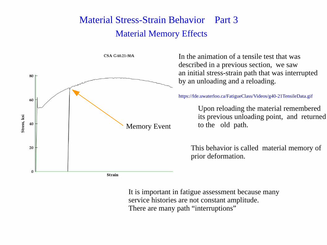
Material Memory Effects
Memory Event
In the animation of a tensile test that wasdescribed in a previous section, we sawan initial stress-strain path that was interruptedby an unloading and a reloading.
https://fde.uwaterloo.ca/FatigueClass/Videos/g40-21TensileData.gif
Upon reloading the material rememberedits previous unloading point, and returnedto the old path.
This behavior is called material memory ofprior deformation.
It is important in fatigue assessment because many service histories are not constant amplitude.There are many path “interruptions”
Material Stress-Strain Behavior Part 3
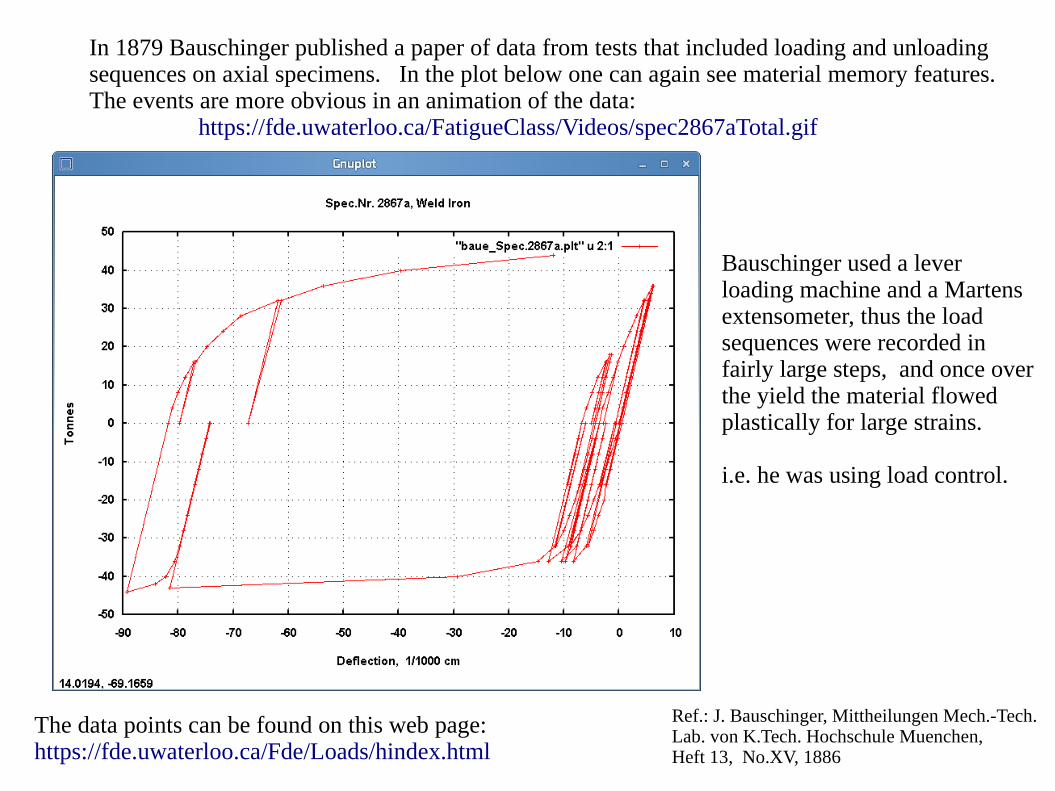
In 1879 Bauschinger published a paper of data from tests that included loading and unloadingsequences on axial specimens. In the plot below one can again see material memory features.The events are more obvious in an animation of the data: https://fde.uwaterloo.ca/FatigueClass/Videos/spec2867aTotal.gif
Bauschinger used a leverloading machine and a Martensextensometer, thus the loadsequences were recorded infairly large steps, and once overthe yield the material flowedplastically for large strains.
i.e. he was using load control.
The data points can be found on this web page:https://fde.uwaterloo.ca/Fde/Loads/hindex.html
Ref.: J. Bauschinger, Mittheilungen Mech.-Tech.Lab. von K.Tech. Hochschule Muenchen,Heft 13, No.XV, 1886
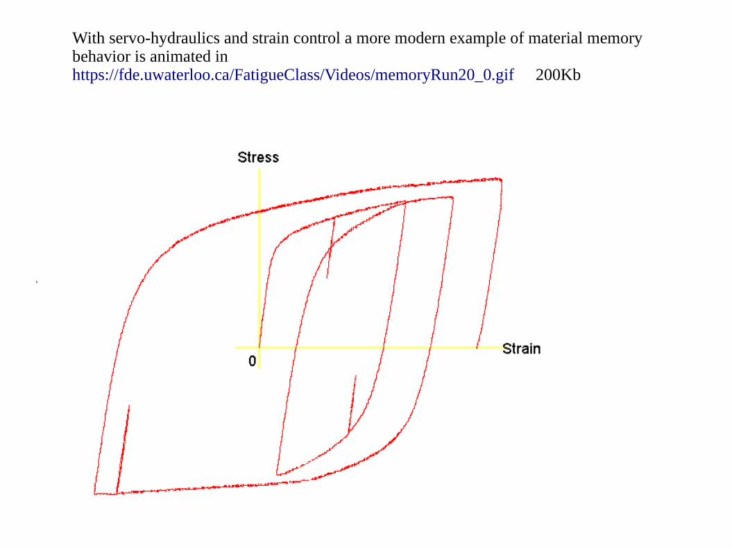
With servo-hydraulics and strain control a more modern example of material memorybehavior is animated inhttps://fde.uwaterloo.ca/FatigueClass/Videos/memoryRun20_0.gif 200Kb
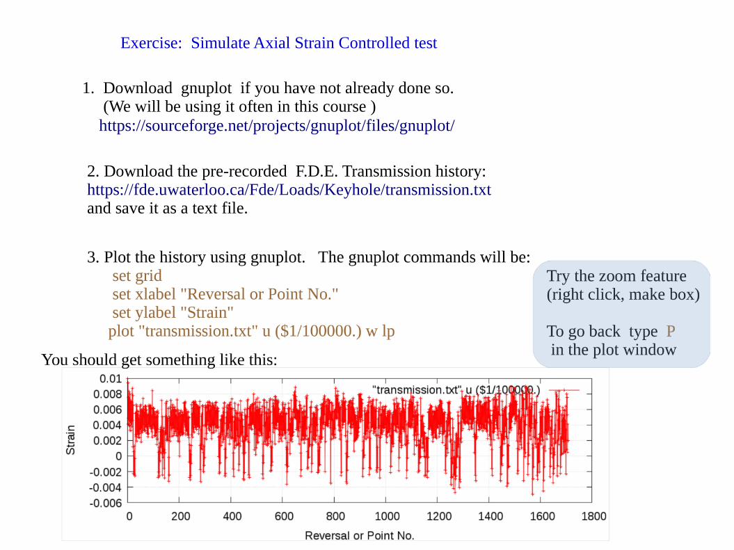
Exercise: Simulate Axial Strain Controlled test
1. Download gnuplot if you have not already done so. (We will be using it often in this course ) https://sourceforge.net/projects/gnuplot/files/gnuplot/
2. Download the pre-recorded F.D.E. Transmission history:https://fde.uwaterloo.ca/Fde/Loads/Keyhole/transmission.txt and save it as a text file.
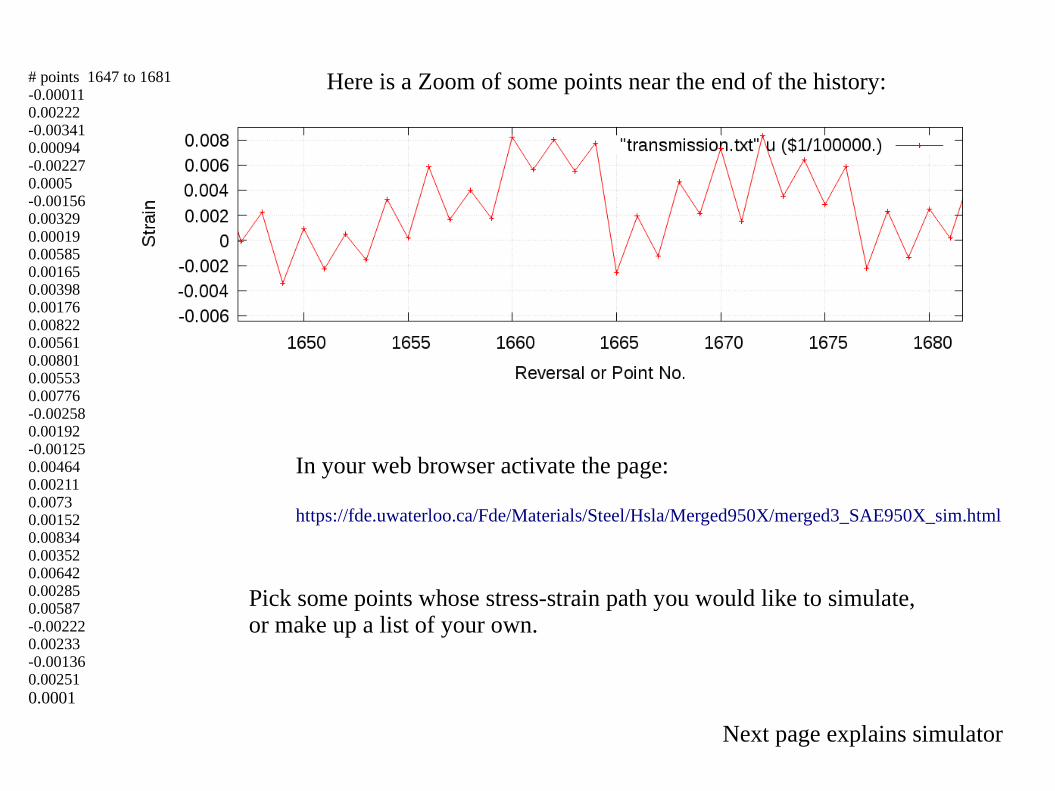
Here is a Zoom of some points near the end of the history:# points 1647 to 1681-0.000110.00222-0.003410.00094-0.002270.0005-0.001560.003290.000190.005850.001650.003980.001760.008220.005610.008010.005530.00776-0.002580.00192-0.001250.004640.002110.00730.001520.008340.003520.006420.002850.00587-0.002220.00233-0.001360.002510.0001
In your web browser activate the page:
https://fde.uwaterloo.ca/Fde/Materials/Steel/Hsla/Merged950X/merged3_SAE950X_sim.html
Pick some points whose stress-strain path you would like to simulate,or make up a list of your own.
Next page explains simulator
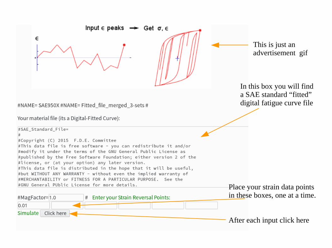
This is just an advertisement gif
In this box you will finda SAE standard “fitted”digital fatigue curve file
Place your strain data points in these boxes, one at a time.
After each input click here
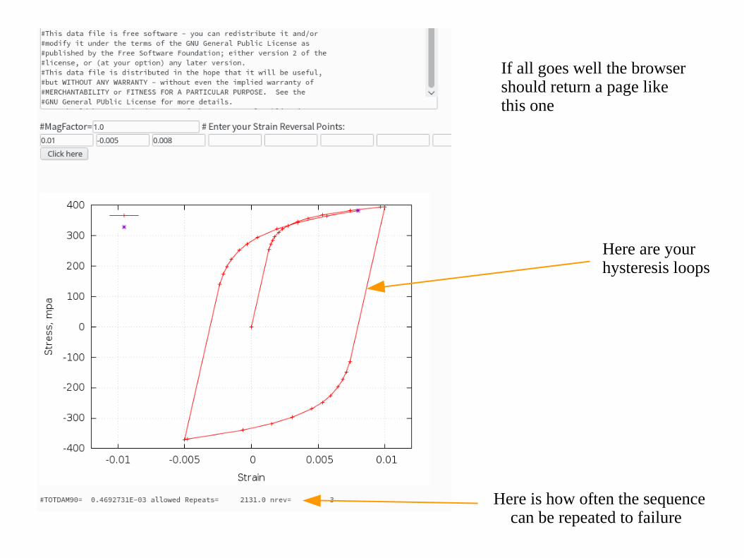
If all goes well the browsershould return a page likethis one
Here are your hysteresis loops
Here is how often the sequence can be repeated to failure
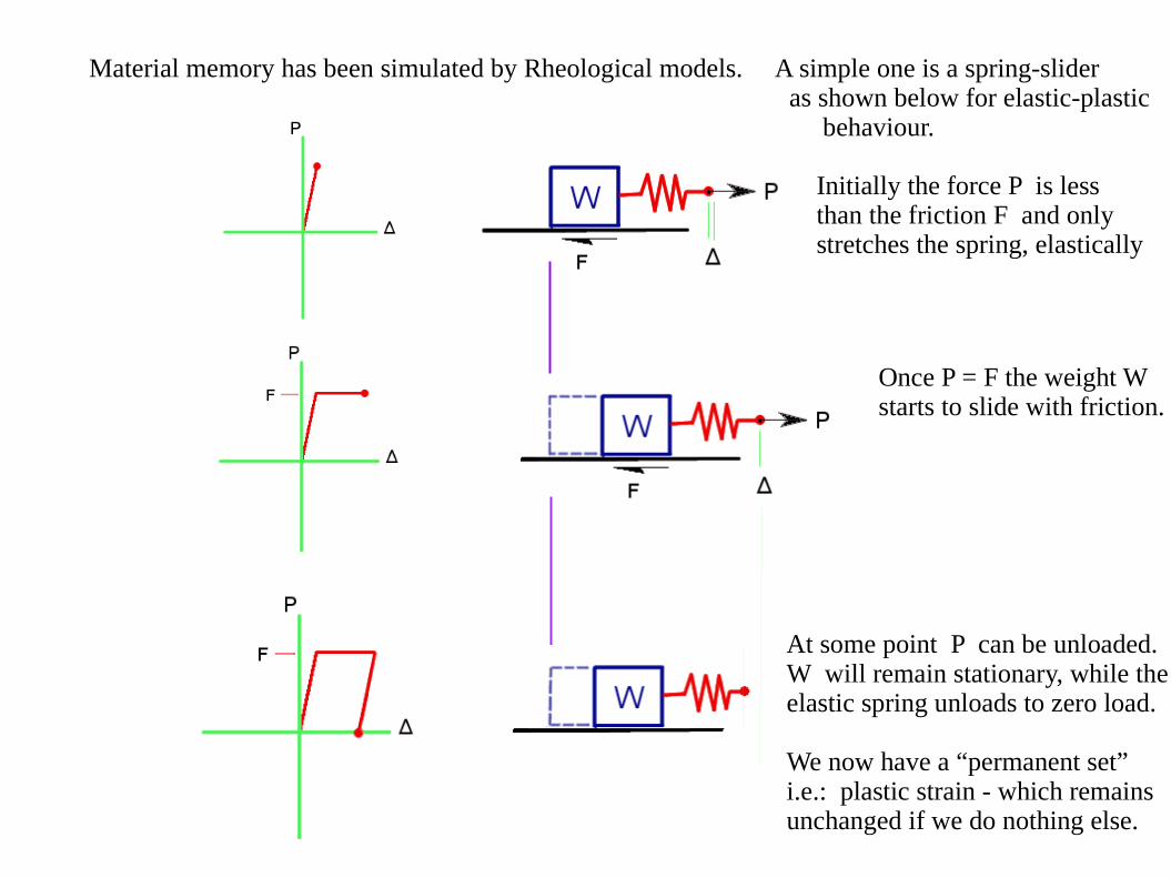
Material memory has been simulated by Rheological models. A simple one is a spring-slider as shown below for elastic-plastic behaviour.
Initially the force P is lessthan the friction F and onlystretches the spring, elastically
Once P = F the weight Wstarts to slide with friction.
At some point P can be unloaded.W will remain stationary, while theelastic spring unloads to zero load.
We now have a “permanent set” i.e.: plastic strain - which remainsunchanged if we do nothing else.
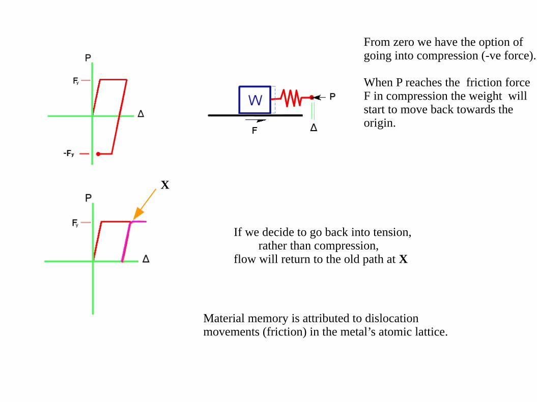
From zero we have the option ofgoing into compression (-ve force).
When P reaches the friction force F in compression the weight willstart to move back towards theorigin.
If we decide to go back into tension, rather than compression,flow will return to the old path at X
X
Material memory is attributed to dislocationmovements (friction) in the metal’s atomic lattice.
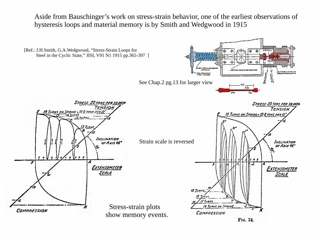
Aside from Bauschinger’s work on stress-strain behavior, one of the earliest observations ofhysteresis loops and material memory is by Smith and Wedgwood in 1915
See Chap.2 pg.13 for larger view
Strain scale is reversed
Stress-strain plots show memory events.
[Ref.: J.H.Smith, G.A.Wedgwood, “Stress-Strain Loops for Steel in the Cyclic State,” JISI, V91 N1 1915 pp.365-397 ]
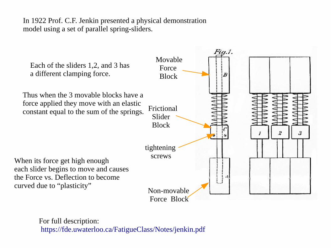
Movable Force Block
Frictional Slider Block
tightening screws
Non-movable Force Block
For full description: https://fde.uwaterloo.ca/FatigueClass/Notes/jenkin.pdf
In 1922 Prof. C.F. Jenkin presented a physical demonstrationmodel using a set of parallel spring-sliders.
Each of the sliders 1,2, and 3 hasa different clamping force.
Thus when the 3 movable blocks have aforce applied they move with an elasticconstant equal to the sum of the springs.
When its force get high enougheach slider begins to move and causesthe Force vs. Deflection to becomecurved due to “plasticity”
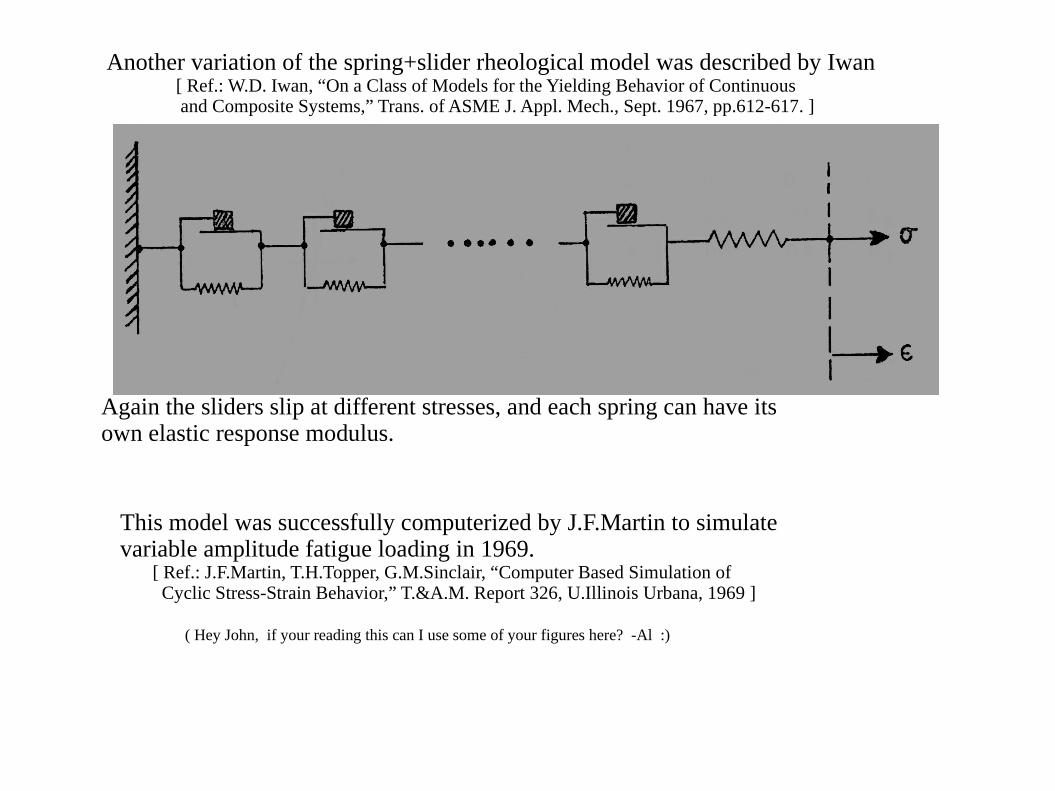
Another variation of the spring+slider rheological model was described by Iwan [ Ref.: W.D. Iwan, “On a Class of Models for the Yielding Behavior of Continuous and Composite Systems,” Trans. of ASME J. Appl. Mech., Sept. 1967, pp.612-617. ]
Again the sliders slip at different stresses, and each spring can have itsown elastic response modulus.
This model was successfully computerized by J.F.Martin to simulatevariable amplitude fatigue loading in 1969. [ Ref.: J.F.Martin, T.H.Topper, G.M.Sinclair, “Computer Based Simulation of Cyclic Stress-Strain Behavior,” T.&A.M. Report 326, U.Illinois Urbana, 1969 ]
( Hey John, if your reading this can I use some of your figures here? -Al :)
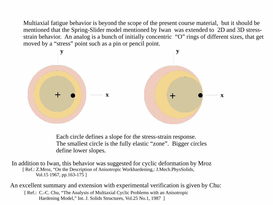
Multiaxial fatigue behavior is beyond the scope of the present course material, but it should bementioned that the Spring-Slider model mentioned by Iwan was extended to 2D and 3D stress-strain behavior. An analog is a bunch of initially concentric “O” rings of different sizes, that getmoved by a “stress” point such as a pin or pencil point.
x
y y
x
Each circle defines a slope for the stress-strain response.The smallest circle is the fully elastic “zone”. Bigger circlesdefine lower slopes.
In addition to Iwan, this behavior was suggested for cyclic deformation by Mroz [ Ref.: Z.Mroz, “On the Description of Anisotropic Workhardening,: J.Mech.PhysSolids, Vol.15 1967, pp.163-175 ]
An excellent summary and extension with experimental verification is given by Chu: [ Ref.: C.-C. Chu, “The Analysis of Multiaxial Cyclic Problems with an Anisotropic Hardening Model,” Int. J. Solids Structures, Vol.25 No.1, 1987 ]
“Why all the emphasis on material memory?”, one could ask.
In my opinion material memory, combined with a cyclic stress-strain curve, is the keyelement of a fatigue crack initiation or a crack propagation analysis that requires prediction of the stress-strain behavior at a fatigue hot-spot.
The transient effects of cyclic hardening/softening do not usually dominate the fatiguelife. For most of the life the cyclic stress-strain curve is adequate for modeling.If needed these transients can be simulated but they are not required to predict fatigue life.
The cyclic mean stress relaxation mechanism (ratcheting in load control) is important when“residual stress” is imposed in the fatigue history. Such stresses are can be created by heattreatments, cold work or the service fatigue history itself. Large plastic strain hysteresis loops will quickly change the “residuals” by cyclic relaxation. This is important for fatiguelife estimations as fatigue hot-spots with tensile mean stress loops will initiate cracksearlier or propagate existing cracks faster. Compressive mean stresses will delay the onsetof the fatigue damage. In order to evaluate the presence or absence of relaxation one must first have a good ideaof the size of the hot-spot stress-strain hysteresis loop and its location in the stress-strainplane. For that one needs a good stress-strain material memory model to follow the variableamplitude component load history.
If the component service loading is constant amplitude only, one does not need to use amaterial memory model. Most service histories, however, have variable amplitude loadings.
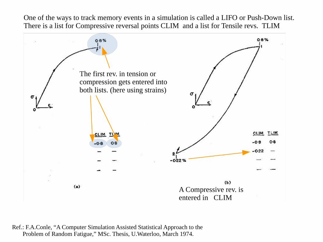
One of the ways to track memory events in a simulation is called a LIFO or Push-Down list.There is a list for Compressive reversal points CLIM and a list for Tensile revs. TLIM
Ref.: F.A.Conle, “A Computer Simulation Assisted Statistical Approach to the Problem of Random Fatigue,” MSc. Thesis, U.Waterloo, March 1974.

If the next tensile rev. does not exceedany previous tens. revs. it is stacked in TLIM
Similarly if the next comp. rev. does not overrunany previous comp. revs, it is stacked in CLIM
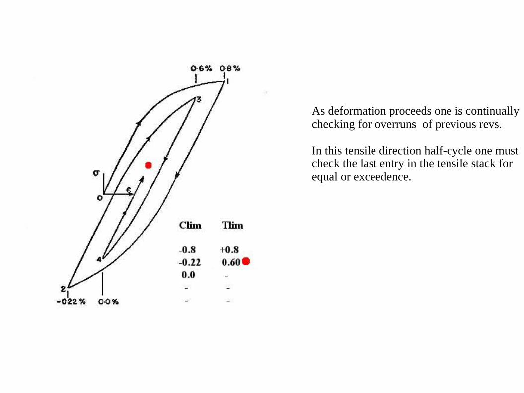
As deformation proceeds one is continuallychecking for overruns of previous revs.
In this tensile direction half-cycle one mustcheck the last entry in the tensile stack forequal or exceedence.
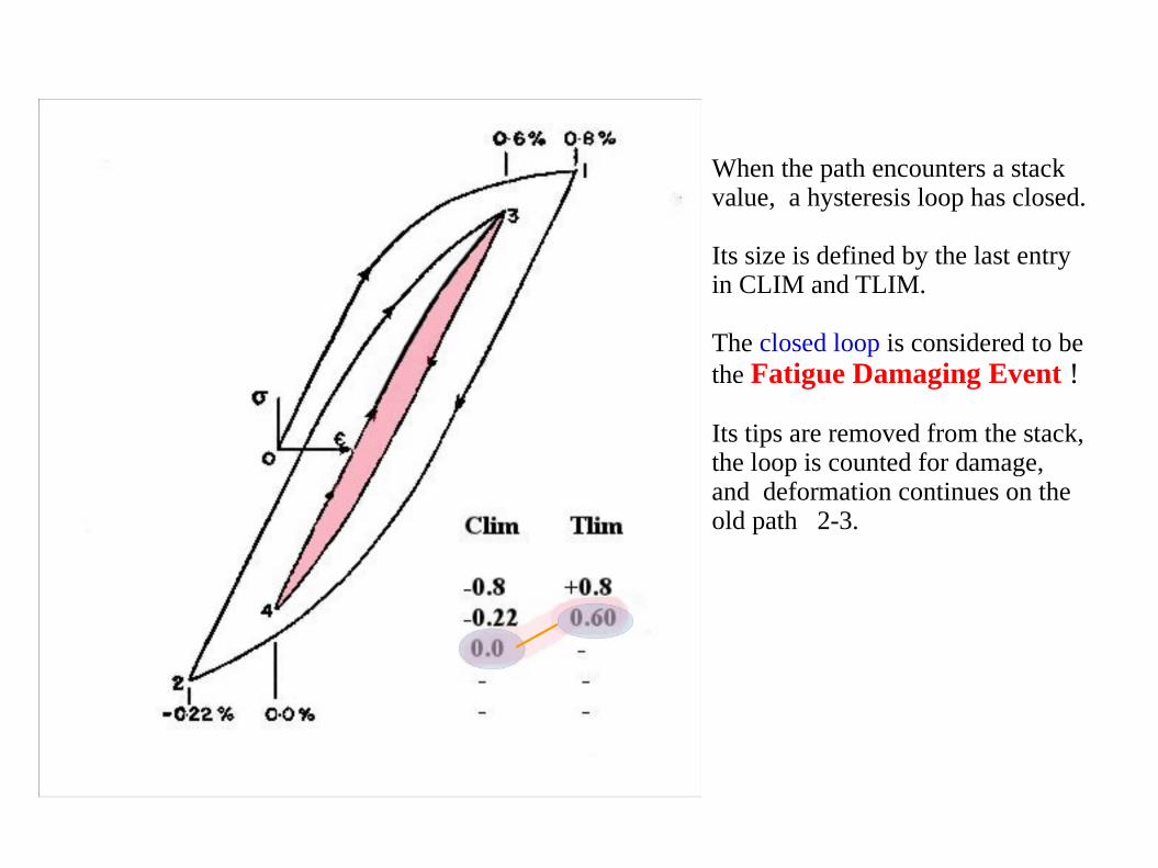
When the path encounters a stack value, a hysteresis loop has closed.
Its size is defined by the last entryin CLIM and TLIM.
The closed loop is considered to be the Fatigue Damaging Event !
Its tips are removed from the stack,the loop is counted for damage,and deformation continues on theold path 2-3.
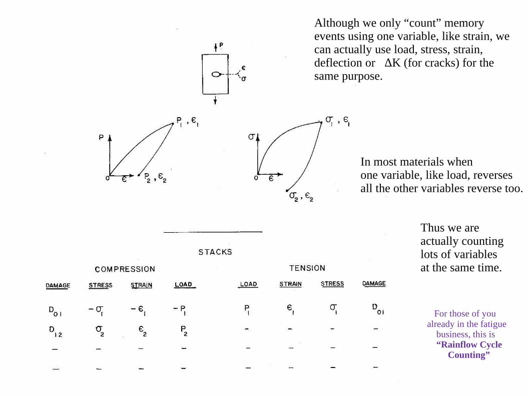
Although we only “count” memoryevents using one variable, like strain, wecan actually use load, stress, strain,deflection or ΔK (for cracks) for thesame purpose.
In most materials whenone variable, like load, reversesall the other variables reverse too.
Thus we areactually countinglots of variablesat the same time.
For those of youalready in the fatigue business, this is “Rainflow Cycle Counting”