Embed Size (px)
Citation preview

MATERIAL SPECIFICATION FOR DOCUMENT 202983
1 MATERIAL NUMBER
202983
2 MATERIAL TYPE/COLOR
2.1 COVERS:
9.0” X 11.5” 80 Lb Grey speckletone. Cover – smooth finish.
Trim cover to 8.5” X 11” with full bleed.
2.2 INTERNAL PAGES
8.5” X 11” 20 Lb. Bond, White Paper, Offset.
2.3 BINDING:
Unicoil Binding System, Color: College Orange, sized to match the document. Cover stock and internal pages will be drilled to match the Unicoil configuration.
3 PRINT COLORS
3.1 FRONT COVER
The front cover will be single-sided, produced using xerographic methods from provided camera-ready originals, or printed directly from provided electronic masters.
3.2 REAR COVER:
The rear cover will be left blank.
3.3 INTERNAL PAGES
Internal pages will be double-sided, produced using xerographic methods from provided single-sided camera-ready originals, or printed from provided electronic masters. All internal copy will be black and white.
4 CERTIFICATION
Certification is not required; however, a packing list with the following information is required:
• MEDRAD Material Number • Purchase Order Number • Quantity Shipped

Avanta Fluid Management Injection System
Operation Manual
202983 Rev. O


MEDRAD Avanta Fluid Management Injection SystemOperation Manual

MEDRAD Avanta Fluid Management Injection System
©2010, MEDRAD, INC. All rights reserved.
Reproduction of this manual is strictly prohibited without express written consent of MEDRAD, INC.
For more information about MEDRAD products and services, please visit WWW.MEDRAD.COM

Table of Contents 1 - Introduction ............................................................................................................ 1-1Certifications ................................................................................................................. 1-2Intended Use ................................................................................................................. 1-2Contraindications .......................................................................................................... 1-2Restricted Sale .............................................................................................................. 1-2Trademarks ................................................................................................................... 1-2Avanta Patents .............................................................................................................. 1-2Disclaimers ................................................................................................................... 1-2MEDRAD Contact Information ...................................................................................... 1-3Symbols ........................................................................................................................ 1-4Warnings ....................................................................................................................... 1-7Cautions ...................................................................................................................... 1-11
2 - System Basics ..................................................................................................... 2-13System Overview ........................................................................................................ 2-13Display Control Unit .................................................................................................... 2-15DCU Sterile Sheath ..................................................................................................... 2-15Injector Head ............................................................................................................... 2-16
Pressure Jacket ................................................................................................... 2-16Syringe ................................................................................................................. 2-18
Fluid Control Module (FCM) ........................................................................................ 2-19MEDRAD Avanta Hand Controller ....................................................................... 2-19MEDRAD Avanta Hand Controller Sterile Sheath ............................................... 2-21Fluid Level Sensors ............................................................................................. 2-22Gross Air Detectors ............................................................................................. 2-22Fluid Bags/Bottles ................................................................................................ 2-22Contrast Heat Maintainers (option) ...................................................................... 2-22Footswitch (option) .............................................................................................. 2-22
Power Unit .................................................................................................................. 2-24Power indicator .................................................................................................... 2-24
Transferring the system .............................................................................................. 2-25Table Mount Bracket ................................................................................................... 2-26System Safety Information .......................................................................................... 2-27Touch Screen Calibration ........................................................................................... 2-27Main Screen ................................................................................................................ 2-27Setup ........................................................................................................................... 2-28Help ............................................................................................................................. 2-29
Screen functions .................................................................................................. 2-29Programming ....................................................................................................... 2-30Service Contact Information ................................................................................ 2-30Customer Service ................................................................................................ 2-30
Reset ........................................................................................................................... 2-30Set Protocol ................................................................................................................ 2-31Storing a Protocol ....................................................................................................... 2-31Recalling a Protocol .................................................................................................... 2-32Deleting a Protocol ...................................................................................................... 2-33
1
MEDRAD Avanta Fluid Management Injection System
3 - Arming and Injecting ........................................................................................... 3-35Minimizing Air Embolization Risks .............................................................................. 3-35Gross Air Detection ..................................................................................................... 3-36Powering up the system .............................................................................................. 3-37Emergency Shutdown ................................................................................................. 3-38Case Setup ................................................................................................................. 3-39Installing a Multi-Patient Syringe ................................................................................. 3-39Disposable Sets .......................................................................................................... 3-40
Install Multi-Patient Disposable Sets ................................................................... 3-40Contrast Flow Control Valve Mechanism (CFCV) ........................................ 3-41Drip Chambers .............................................................................................. 3-41
Fill Syringe ........................................................................................................... 3-47Purge Contrast ..................................................................................................... 3-48Purge Saline ........................................................................................................ 3-50Install Single-Patient Disposable Set ................................................................... 3-52Purge Contrast ..................................................................................................... 3-54Purge Saline ........................................................................................................ 3-55Calibrate Hemodynamic Transducer ................................................................... 3-56
Refilling a Syringe ....................................................................................................... 3-57Auto Fill ................................................................................................................ 3-57Manual Fill ........................................................................................................... 3-57To fill a syringe ensure the following: ................................................................... 3-57
Arming the injector ...................................................................................................... 3-59Variable Mode ...................................................................................................... 3-59Fixed Mode .......................................................................................................... 3-59
Check for Air ............................................................................................................... 3-60Pressure Limit ............................................................................................................. 3-61Response to Occlusions ............................................................................................. 3-61Volume and Rate Protection ....................................................................................... 3-62Saline injection ............................................................................................................ 3-62Fixed Rate Injection .................................................................................................... 3-63Variable Rate Injection ................................................................................................ 3-64Injection Complete ...................................................................................................... 3-65End Case .................................................................................................................... 3-65Remove Single-Patient Disposable Set ...................................................................... 3-65Remove Multi-Patient Disposable Set ........................................................................ 3-66
4 - ISI Option .............................................................................................................. 4-67Introduction ................................................................................................................. 4-67Intended Use ............................................................................................................... 4-67Important Safety Notice .............................................................................................. 4-67Warnings ..................................................................................................................... 4-67Cautions ...................................................................................................................... 4-67ISI Configuration ......................................................................................................... 4-68ISI Operation ............................................................................................................... 4-68ISI System Messages ................................................................................................. 4-70ISI Basic Functionality ................................................................................................. 4-70ISI Operational Checkout ............................................................................................ 4-71ISI Technical Specifications ........................................................................................ 4-71
2

5 - Cleaning and Maintenance ................................................................................. 5-73Cleaning Guidelines .................................................................................................... 5-73Recommended Maintenance Schedule ...................................................................... 5-77Pressure Jacket Use Life: ........................................................................................... 5-78Inspection Procedures ................................................................................................ 5-78Operational Checkout ................................................................................................. 5-79
6 - Specifications ...................................................................................................... 6-83DCU ............................................................................................................................ 6-83Injector Head ............................................................................................................... 6-83Power Unit .................................................................................................................. 6-83Fluid Control Module ................................................................................................... 6-84Table Mount Bracket ................................................................................................... 6-84Environmental Specifications ...................................................................................... 6-86
7 - System Installation .............................................................................................. 7-89Unpacking the Injection System .................................................................................. 7-89Installation Considerations .......................................................................................... 7-91Injector Installation ...................................................................................................... 7-92Pressure Jacket Installation ........................................................................................ 7-93Catalog Numbers ........................................................................................................ 7-94Table Mount Bracket Installation ................................................................................. 7-95Pedestal Installation .................................................................................................... 7-96ISI Installation (option) ................................................................................................ 7-97
Index .......................................................................................................................... 8-99
3

MEDRAD Avanta Fluid Management Injection System
4

1 - Introduction
1 - Introduction
Important Safety Notice to Users of the Avanta Fluid Management Injection System
This manual and the equipment it describes are for use only by qualified medical professionals with adequate training and experience in angiographic procedures and the use of the MEDRAD Avanta Fluid Management Injection System (MEDRAD Avanta). It is intended as a guide for using both the Injector and dedicated Medrad Avanta disposables.
The Avanta Fluid Management Injection System contains a gross air detection feature which is intended to assist qualified medical professional users/operators during injections to detect gross air contained in the Multi-Patient Disposable Set. As noted throughout this manual, operator vigilance is always required to eliminate potential air hazards during use.
The safe and effective use of the Avanta Fluid Management Injector System to a large degree depends upon factors solely under the control of the medical professionals using the system. There is no substitute for a properly trained and vigilant angiographic team. It is important that the operating instructions and user warnings supplied with this Injection System be read, understood and followed.
Before starting any angiographic injection procedure the angiographic team should be trained in the particular angiographic procedures to be performed, and should be familiar with the medical literature related to angiographic procedures and the potential complications and risks versus the benefits of utilizing angiographic fluid injection procedures.
This manual is intended as an extension of the user interface of the MEDRAD Avanta Fluid Management Injection System to provide procedural and technical information. Additional MEDRAD Avanta training information is available in the following formats:
• On-site in-service sessions• In-service video• Service manual• Package inserts (IFU).
Please do not hesitate to contact MEDRAD if any of these resources are needed.
1 - 1

MEDRAD Avanta Fluid Management Injection System
This manual applies to the MEDRAD Avanta Fluid Management Injection System.
Read all the information contained in this manual. Understanding this information will assist you in operating the MEDRAD Avanta in a safe manner.
Certifications This device is equipped to operate at 100-240 VAC, 50/60 Hz, and is designed to comply with EN 60601-1 (safety), and IEC-60601-1-2 / 2nd edition Standards.
Intended Use The MEDRAD Avanta is specifically intended for operation in the x-ray angiography environment. It is designed to administer intravascular radio-opaque contrast compounds, and common flushing agents at various volumes and flow rates into humans for use in diagnostic and interventional angiographic procedures performed in cardiology, radiology, and vascular surgery.
Contraindications This device is not intended to be used for chemotherapy and is not intended to administer fluids other than intravascular contrast agents and common flushing solutions.
Restricted Sale RX Only.
Trademarks MEDRAD, Fluidot, and MEDRAD Avanta are trademarks of MEDRAD, INC. Other trademarks which appear in this manual are the property of their respective companies.
Avanta Patents Disposables: 5,873,861, 5,947,935, 6,808,513, 7,094,216, 6,866,654.
Injector: D542,911, D545,967, D536,454, Re 37,487, 5,899,885, 6,371,938, 6,974,443, 6,921,384, 6,442,418, 6,731,971, 7,326,186, 7,081,105, EP 0 851 775, EP 1 243 279, EP 1 572 266.
Disclaimers External wiring and modifications disclaimers: MEDRAD disclaims liability for any modifications or interfaces with other equipment that are not in conformity with the specifications and information contained within this manual.
Accessory equipment connected to the MEDRAD Avanta Fluid Management Injection System must be certified according to IEC 60601-1 standard. Furthermore, all configurations shall comply with system standard IEC 60601-1-1. Anyone who connects additional equipment to the signal input or output part configures a medical system and is therefore responsible that the system complies with the requirements of the standard IEC 60601-1-1. To obtain on-site consulting or consulting references, contact MEDRAD Service.
1 - 2

1 - Introduction
MEDRAD Contact Information
MEDRAD, INC.One Medrad DriveIndianola, Pa 15051-0780U.S.APhone: 412 767-2400Fax: 412-767-4128
MEDRAD Europe B.V.Postbus 2056190 AE BeekThe NetherlandsPhone: +31(0)43-3585601Fax: +31(0)43-3656598
Nihon MEDRAD KK2-4-9, Umeda, Kita-ku,Osaka, 530-0001JapanPhone: +81(0)66-133-6250Fax: +81(0)66-344-2395
1 - 3

MEDRAD Avanta Fluid Management Injection System
Symbols The following symbols are used on the MEDRAD Avanta Fluid Management Injection System and components:
Indicates that this device conforms to the requirements of the European Medical Device Directive 93/42/EEC.
Attention, consult accompanying instructions.
High voltage.
Pinch/crush hazard (Pedestal & Table Mount Bracket)
Check for Air icon.
Fluid delivery indicator.
WARNING: Indicates that the information is a warning. Warnings advise you of circumstances that could result in injury or death to the patient or operator. Read and understand the warnings before operating the injection system.
CAUTION: Indicates that the information is a caution. Cautions advise you of circumstances that could result in damage to the device. Read and understand the cautions before operating the injection system.
NOTE: Indicates that the information that follows is additional important information or a tip that will help you recover from an error or point you to related information within the manual.
Indicates hot surface. Item can be hot and should not be touched without taking care.
Pedestal height adjustment/range of motion. Raising/Lowering symbol on handle. (Pedestal)
Lock and release for Pedestal.
Lock and release for DCU arm.
Lock and release for Table Mount Bracket.
Indicates on/off switch (Rear of DCU)
Code that specifies the degree of protection against vertically falling water drops (IEC 60529) (Power Unit)
1 - 4

1 - Introduction
Identifies the Equipotential connection (Power Unit)
Identifies the Earth Ground point (internal - Power Unit)
Syringe Heat Maintainer connection (Injector head)
Footswitch connector (Fluid Control Module)
Type CF Defibrillation-Proof applied part (IEC 60417-2)
Connector, DCU interface cable (Power Unit)
Connector, Hand Controller
Service Port Connector (Power Unit)
Service Port Connector (DCU)
Brightness Up (+) and Down (-) (DCU)
Bottle Heat Maintainer (Fluid Control Module)
Head cable connector (Power Unit)
ISI connection (Power Unit)
Screen display: The injector is configured for ISI and it is operational.
Data connection (Power Unit) (future implementation)
Do not dispose of in municipal waste. Wheeled bin symbol indicates separate collection for electrical and electronic equipment. (WEEE Directive 2002/96/EEC) (Power Unit) For more information on MEDRAD’s European WEEE Recycling policy, please visit www.medrad.com.
IV pole volume limit. Less than or equal to 1000 mL for saline bag and contrast bottle.
1 - 5

MEDRAD Avanta Fluid Management Injection System
Non Pyrogenic.
Non-Pyrogenic Fluid Path.
Do not use if package is opened or damaged.
Single Use Only
Date of Manufacturer/Sterilization
Use By
Lot Number
Catalog Number
Sterilized with Ethylene Oxide
Sterilized using irradiation.
Latex Free
Warning - Advises you of circumstances that could result in injury or death to the patient or operator.
Caution - Advises you of circumstances that could result in damage to the device.
Indicates Alternating Current.
NON-PYROGENIC
NON-PYROGENIC
FLUID PATH
DO NOT USE IF PACKAGE IS OPENED OR DAMAGED
STERILE EO
LATEX FREE
Warning
Caution
1 - 6

1 - Introduction
Warnings Patient injury or death could result from an air embolism.
• Do not connect a patient to the injector, or attempt an injection until all trapped air has been cleared from the syringe and fluid path.
• Expel all trapped air from the syringe, drip chambers, connectors, tubings, and catheter before connecting the system to the patient. Carefully read the instructions for loading and the use of FluiDot™ indicators (where applicable) to reduce the chance of air embolism.
• To minimize air embolization risks, ensure that one operator is designated as being responsible for filling the syringe(s). Do not change operators during the procedure. If an operator change must occur, ensure that the new operator verifies that the fluid path is purged of air.
• The presence of rounded FluiDot indicators does not indicate the total absence of air bubbles in the syringe tip. Carefully read the instructions for use about filling the syringe and the use of FluiDot indicators to reduce the chance of air embolism.
• Do not fill or inject unless the syringe is properly engaged with the injector head. Improper engagement may cause an under volume delivery, air embolization or personal injury.
• Do not attempt to aspirate fluid from the waste port stopcock when open to the PIV. Doing so may increase the risk of inducing air into the fluid path.
• Do not attempt to aspirate fluid from the hemodynamic port. Doing so may increase the risk of inducing air into the fluid path.
• Once the Single-Patient Sterile Disposable Set (SPDS) is connected to the patient, ensure all stopcocks are closed to air and all air is removed from the fluid path before injection. Improper manipulation of the waste port stopcock may increase the risk of inducing air into the fluid path.
• Verify no air is present in the tubing between the drip chamber and fluid source. • Verify that the fluid path is open and free of air before attempting an injection.
Patient injury could result from leaks or ruptures during an injection. To prevent leaks or ruptures in the event of a blockage, use only MEDRAD disposable products.
Patient injury can result if the patient is connected during any contrast or saline purge. Ensure the patient is disconnected before any purge.
Patient injury can result if the patient is connected when the "Engage Plunger" button is pressed. Ensure the patient is disconnected before pressing engage plunger button.
Patient or operator injury may result if damaged components are used. Do not use damaged components. Visually inspect all components before use.
Patient injury may result if the injector head or pedestal is moved while the catheter is connected to the patient. Ensure the catheter is disconnected from the patient before moving the injector.
Pinching can occur if the Superstructure and the table are not mated properly during transfer, installation and/or removal. To avoid pinch points and personal injury, use care and diligence while mating the Superstructure to the table and the Superstructure with the pedestal interface. Keep hands and fingers clear of all pinch point areas.
1 - 7

MEDRAD Avanta Fluid Management Injection System
Patient or operator injury may result if the injection system is moved without locking the Superstructure and/or extension arm. Failure to do so may result in disengagement or adverse movement of the Superstructure or DCU. Do not move the injection system without locking the Superstructure to the pedestal and the DCU to the extension arm. Do not use the system to inject unintended media. The injection system has only been validated for its specified intended use. There may be additional risks associated with use of the system for other purposes due to insufficient performance specifications, or operational safeguards. Contact MEDRAD for additional information.Blood can contaminate the multi-patient portion of the disposable set. Ensure that blood does not appear past the pressure isolation valve in the single patient disposable set.Personal injury and/or equipment damage may result if screws, clamps and knobs are not tightened on the pedestal. Loose components may cause the pedestal to collapse. Tighten all screws, clamps and knobs during assembly of the pedestal and as needed during use. Injector may disarm or fail to operate upon exposure to high electromagnetic fields that may be generated by radio transmitters or cellular phones, or upon exposure to high levels of electrostatic discharge. Turn off any equipment that could generate an electrostatic discharge.Patient injury may result from a system malfunction. If a system malfunction occurs, immediately remove unit power by pressing the On/Off switch on the Display Control Unit and disconnecting the unit from the patient. If a fault message is displayed that cannot be corrected, and/or the system is not operating correctly, do not use the injection system. Call MEDRAD or your local dealer for assistance.Biological contamination can result from reusing disposable items or failure to follow sterile technique during setup or use. Properly discard disposable items after use. If there is any possibility that contamination may have occurred during set-up or use, disassemble and setup a new sterile product.Patient injury could result from high flow rate injections. Use extreme care when selecting the flow rate. Before arming the injector, verify that high flow rate injection parameters are correct.Patient or operator injury may result from mishandling of the sharp spike. Use care in handling and inserting the spike into the contrast bottle and the saline bag or bottle.
Pressure settings must be lower than catheter and other disposables ratings. If a blockage occurs, tubing with a lower pressure rating may be subjected to pressure beyond its capability resulting in a failure. Always verify that the pressure setting on the injector is lower than the maximum ratings of any disposables.
Patient injury could result if contrast crystallizes within the multi-patient or single- patient disposable sets. Regularly check the disposable sets for crystallized contrast and discard if present.Biological contamination can result from reusing disposable items or by not following sterile technique. Discard the DCU and Hand Controller sterile sheath after every use. Replace sterile sheath if damaged.Patient or operator injury or component damage may occur if an injection is performed without pressure jacket in place. Ensure pressure jacket is in place before performing an injection.
1 - 8

1 - Introduction
Operator injury may occur if Peristaltic Pump is operating with the door open. A pinch point exists due to rotating mechanical parts. Do not operate Peristaltic Pump with the door open.Ensure vent cap on contrast spike is open, if closed it may create a vacuum and air may be introduced. For all body fluid spills/contamination, follow institutional decontamination procedures. If contrast medium has leaked inside any component of the system, the affected subassembly should be disassembled and cleaned by MEDRAD Service personnel or returned to MEDRAD Factory service.
Inadvertent aspiration can occur if the Multi-Patient disposable contrast tubing set is kinked or blocked during a syringe fill process. Verify multi-patient contrast tubing is free of kinks before attempting to fill the syringe.
Patient and/or operator injury or system malfunction may result if the exam table is not horizontal in both planes during an injection when using the Table Mount Bracket Configurations (1 and 2). Ensure that the table is horizontal in both planes at all times when using the Table Mount Bracket Configurations (1 and 2).
Do not position the injector by pulling on the head or cabling, or by applying force at the syringe tip. Possible injury can occur if the injector head or stand falls on the patient or technologist. Move the injector by grasping the center of the handle, and by pulling or pushing the injector into place.
Storage of filled syringes can promote bacterial growth. MEDRAD syringes are designed to be filled just prior to the procedure. Discard unused filled syringes.
Use of non-MEDRAD supplied accessories (heat maintainers, hand controller, footswitch, power cable, ISI cable) and replacement parts for internal components may result in increased emissions or decreased immunity for the equipment or system. Use only MEDRAD supplied accessories and replacement parts.
Explosion hazard: Explosion risk may exist if the system is used in the presence of flammable anaesthetic mixtures, and/or flammable agents for disinfection and/or skin cleaning.
Fire hazard: To avoid an electrical fire, the injector fuse must be replaced with the appropriate fuse-type by qualified personnel only. Fuses are located on the signal management board (heat maintainers) of the head module and also with the Power Unit module.
Electrical Shock hazard: Serious injury or death may result from exposure to hazardous voltages existing within the system. Operator injury could result from worn cabling or unit disassembly. To avoid exposure to potentially hazardous voltages, do not disassemble the injection system in any way. Worn cabling also creates voltage hazards. If any worn or damaged cables are detected, do not use the injection system. Contact MEDRAD or your local dealer for service or replacement.
Burn hazard: Operator injury may result if contact is made with the heater element. Do not touch the bottle or syringe heat maintainer heater elements.
1 - 9

MEDRAD Avanta Fluid Management Injection System
Electrical Shock hazard: Operator injury could result from cleaning the unit while connected to line power. In order to avoid shock and prevent damage to the injector, always disconnect the unit from line power before cleaning. Remove unit power by pressing the On/Off switch at the rear of the Power Unit module or by disconnecting the power cord from the wall outlet or from a power source. Ensure that the system is completely dry before connecting to a power source and applying power.
Electrical Shock hazard: Operator injury could result from using an extension cord or power adapter with the system. Plug the injector directly into a properly grounded AC power outlet. Since the injector power cord supplies a safety ground to the unit, using an extension cord will compromise the ground quality and the injector could become unsafe.
Only use the power cord supplied with the system. Do not plug the MEDRAD Avanta Fluid Management Injection system power cord into an extension cord or multi-outlet power strip.
1 - 10

1 - Introduction
Cautions Damage can occur as a result of incorrect voltage. Verify that the voltage and frequency marked on the serial tag on the back of the Power Unit module matches the voltage and frequency of the electrical outlet.DO NOT hang items on the Display Control Unit, its mounting arm or any other component of the system. Hanging items on the Display Control Unit or other components may result in failure of the mounting system and can result in personal injury and/or equipment damage.Component damage may occur if disposables are not installed properly. Assure all connections are secure. This will help minimize leaks, disconnections, air introduction, and component damage. Do not use tools to over tighten connections or to assist in removal of disposables.Component damage may occur if the Table Mount Bracket lock is not released prior to removal of components. Ensure lock is released before removal.Do not remove any covers or disassemble any parts of the system. The system does not contain user serviceable parts. Refer to the MEDRAD Avanta Fluid Management Injection System Service Manual (202982) for information regarding replacement of the Power Unit air filter. Periodically inspect for loose or frayed cables, loose covers, cracks, dents, or loose hardware. Contact MEDRAD Service for repairs.Do not use strong industrial cleaning solvents such as acetone to clean the system or any parts. Only use warm water and a mild disinfectant to clean and wipe down.Do not spray cleaning solutions directly onto the touch screen. To prevent damage, wipe the touch screen with a soft non-abrasive cloth or paper towel dampened with water soluble cleaning solution.Improper or careless cleaning methods may result in equipment damage. Do not soak or immerse any part of the injection system in water or cleaning solutions. While cleaning any outside portion of the system, avoid allowing any water or cleaning solutions to leak inside system components. System malfunction may be caused by failure to perform regular maintenance. Regular preventive maintenance is recommended to ensure that the system stays calibrated and functions properly. Refer to this manual or contact MEDRAD for additional information.Component damage could occur if the pedestal rolls over the cables. When moving the pedestal, ensure the cables are out of the way.Component damage may occur if excessive weight is hung on the IV pole hooks. Do not exceed a 1000 mL bag or bottle of saline or contrast on one hook of the IV pole.Component damage may occur if fluid is pulled into the Power Unit vents. If the Power Unit is located remotely, ensure that it is placed away from any puddles of fluid or spills.Component damage may occur if the table rail cannot withstand a minimum vertical static load of 36.3 kg (80 lbs.) Before installing the Table Mount Bracket, ensure the table rail can withstand a minimum vertical static load of 36.3 kg (80 lbs.) Refer to the table manufacturer documentation for weight load information.All contrast media should be used in accordance with the manufacturer’s indication for use.Use of methyl alcohol will degrade the integrity of the disposable sets. Do not use methyl alcohol on disposable sets. Component damage may occur if the MEDRAD Avanta Handcontroller is immersed in fluid. Avoid immersion when using the Handcontroller unsheathed.
1 - 11

MEDRAD Avanta Fluid Management Injection System
Over tightening the knobs may cause the Table Mount Bracket to work improperly. Do not over tighten the knobs.
Forcing the Table Mount Bracket onto an incorrectly sized table rail could damage the bracket or table rail. Do not force the bracket onto the table rail.
Additional warnings, cautions and notes are located throughout this manual, where applicable.
1 - 12

2 - System Basics
2 - System Basics
System Overview The system configurations include table mount brackets for the fluid delivery and display components, as well as a movable pedestal mounting of the components. The injector tower may be mounted directly to the moveable pedestal or used remotely.
The MEDRAD Avanta Fluid Management Injection System provides the following features:
• Variable rate which can be modulated by the physician during the injection• Fixed rate programmable flow of contrast up to 45 mL/sec.• Variable rate programmable flow of contrast up to 10 mL/sec.• Programmable filling and refilling of syringes during a procedure without requiring
disconnection of the disposable set from the patient• Fluid level sensing to ensure syringe filling and fluid delivery only when a fluid supply is
available• User accessible control, enabling solo operation of the injector during a patient procedure• Gross air detector• Saline injection for purging and flushing• Multi-Patient disposable components that may be used for up to five patients• Disposable Hand Controller that provides control of contrast and saline injections• Sharp bolus at the end of contrast injections.
Pedestal Configuration
Fluid Control Module
Injector Head
Superstructure
Raising/Lowering Symbol
Height adjustmentpaddles
Power Unit
DCU
DCU Post
DCU ArmExtension Arm
Clevis pin
Fluid Delivery Assembly =FCM + Head + Superstructure
Display Assembly =DCU + DCU Post
2 - 13

MEDRAD Avanta Fluid Management Injection System
Caution: Component damage may occur if the Table Mount Bracket lock is not released prior to removal of components. Ensure lock is released before removal.
Caution: Component damage may occur if the table rail cannot withstand a minimum vertical static load of 36.3 kg (80 lbs.) Before installing the Table Mount Bracket, ensure the table rail can withstand a minimum vertical static load of 36.3 kg (80 lbs.) Refer to the table manufacturer documentation for weight load information.Caution: Over tightening the knobs may cause the Table Mount Bracket to work improperly. Do not over tighten the knobs.
Caution: Forcing the Table Mount Bracket onto an incorrectly sized table rail could damage the bracket or table rail. Do not force the bracket onto the table rail.
Table Mount Bracket Configuration Table Mount Bracket Configuration (2 Table Mount Brackets) (1 Table Mount Bracket)
2 - 14
2 - System Basics
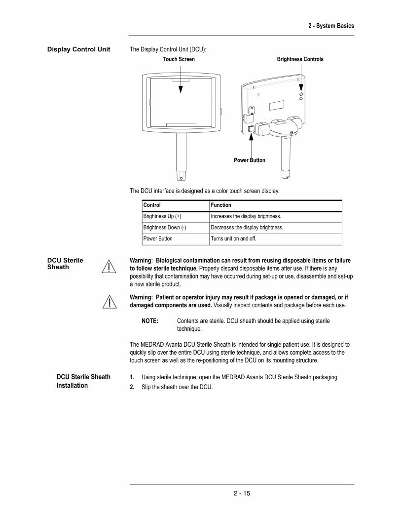
Display Control Unit The Display Control Unit (DCU):Brightness ControlsTouch Screen
Power Button
The DCU interface is designed as a color touch screen display.
Control Function
Brightness Up (+) Increases the display brightness.
Brightness Down (-) Decreases the display brightness.
Power Button Turns unit on and off.
DCU Sterile Sheath
Warning: Biological contamination can result from reusing disposable items or failure to follow sterile technique. Properly discard disposable items after use. If there is any possibility that contamination may have occurred during set-up or use, disassemble and set-up a new sterile product.
Warning: Patient or operator injury may result if package is opened or damaged, or if damaged components are used. Visually inspect contents and package before each use.
NOTE: Contents are sterile. DCU sheath should be applied using sterile technique.
The MEDRAD Avanta DCU Sterile Sheath is intended for single patient use. It is designed to quickly slip over the entire DCU using sterile technique, and allows complete access to the touch screen as well as the re-positioning of the DCU on its mounting structure.
DCU Sterile Sheath Installation
1. Using sterile technique, open the MEDRAD Avanta DCU Sterile Sheath packaging.2. Slip the sheath over the DCU.
2 - 15

MEDRAD Avanta Fluid Management Injection System
3. Ensure that the sheath completely covers the DCU.
Injector Head The injector head pivots at least 90 degrees above the horizontal plane. This feature is to maximize the buoyancy force of air for purging. The head also pivots at least 70 degrees below the horizontal plane. This feature is to trap any remaining air in the back of the syringe during injection.All lighting controlled by the head illuminates at power up to allow confirmation of operation. The lights stay on from two to ten seconds.
Armed lights
Drop front arms
Pressure Jacket
Pressure Jacket Important Safety Notice: The MEDRAD Avanta pressure jacket is intended to be used by medical professionals with adequate training and experience in the operation of the MEDRAD Avanta Fluid Management Injection System and angiographic procedures and techniques.The pressure jacket must be used to ensure the integrity of the syringe.
Warning: Patient or operator injury or component damage may occur if an injection is performed without pressure jacket in place. Ensure pressure jacket is in place before performing an injection.
Warning: Patient injury or death could result from an air embolism.
• Do not connect a patient to the injector, or attempt an injection until all trapped air has been cleared from the syringe and fluid path.
• Expel all trapped air from the syringe, drip chambers, connectors, tubings, and catheter before connecting the system to the patient. Carefully read the instructions for loading and
2 - 16

2 - System Basics
the use of FluiDot™ indicators (where applicable) to reduce the chance of air embolism.• To minimize air embolization risks, ensure that one operator is designated as being
responsible for filling the syringe(s). Do not change operators during the procedure. If an operator change must occur, ensure that the new operator verifies that the fluid path is purged of air.
• The presence of rounded FluiDot indicators does not indicate the total absence of air bubbles in the syringe tip. Carefully read the instructions for use about filling the syringe and the use of FluiDot indicators to reduce the chance of air embolism.
• Do not fill or inject unless the syringe is properly engaged with the injector head. Improper engagement may cause an under volume delivery, air embolization or personal injury.
• Do not attempt to aspirate fluid from the waste port stopcock when open to the PIV. Doing so may increase the risk of inducing air into the fluid path.
• Do not attempt to aspirate fluid from the hemodynamic port. Doing so may increase the risk of inducing air into the fluid path.
• Once the Single-Patient Sterile Disposable Set (SPDS) is connected to the patient, ensure all stopcocks are closed to air and all air is removed from the fluid path before injection. Improper manipulation of the waste port stopcock may increase the risk of inducing air into the fluid path.
• Verify no air is present in the tubing between the drip chamber and fluid source. • Verify that the fluid path is open and free of air before attempting an injection.
Warning: Failure to properly install the pressure jacket may result in rupture of the syringe. Ensure that the pressure jacket has been properly installed prior to an injection.Warning: The pressure jacket should be replaced at the first sign of physical deterioration. Failure to do so may result in the pressure jacket fracturing during a high pressure injection.
Prior to each procedure, inspect the pressure jacket for signs of deterioration or fatigue by looking through it with light shining through the pressure jacket.
Rotate the pressure jacket while looking through it to view all areas. This includes the front edges and the entire cylindrical surface.
A pressure jacket should be rejected for cracks, crazing, scratches (if a fingernail can catch on the scratch), and opacity. These faults indicate that the pressure jacket has been weakened and may fracture during a high pressure injection. The pressure jacket should NOT BE USED if any of these conditions exist.
2 - 17

MEDRAD Avanta Fluid Management Injection System
Cracks are usually the result of a sharp impact (such as from dropping). A crack may appear simply as a line, usually originating at the radius or edge and may also appear in conjunction with crazing.
Cracks
Stress Cracks may appear after the pressure jacket has been subjected to a number of pressure cycles. These tiny cracks appear around the front area of the pressure jacket, and usually form a pattern around the jacket’s circumference. Stress cracks are easiest to see while rotating the pressure jacket in front of a light source.
Stress cracks
Crazing can occur when non-compatible cleaning solutions or solvents are used on the pressure jacket. Crazing can also occur when the pressure jacket has reached the end of it’s expected life. crazing appears as small lines that interfere with the transparency of the pressure jacket. Crazing usually appears several together or interconnected, localized to a point of impact or fatigue.
Crazing
Scratches result from objects striking or scraping the inside or outside surface of the pressure jacket. Scratches may occur when the pressure jacket is improperly handled. Check depth of scratches by pulling your finger across the scratch, perpendicular to the surface. If your fingernail catches on a scratch, The pressure jacket should NOT BE USED.
Scratches
Normally the pressure jacket is transparent, enabling you to clearly see through the barrel.
Opacity
The pressure jacket is manufactured from high impact resistant material; however, sharp impacts such as from dropping may cause small barely visible cracks to form, which may propagate during subsequent pressure cycles.
Pressure Jacket Storage
When not in use, the pressure jacket should remain securely attached to the injector head. Alternately, the pressure jacket may be wrapped in a cloth and stored where it will not be hit or dropped.For cleaning and sterilization of the pressure jacket refer to the "Pressure Jacket" subheading in the Cleaning and Maintenance section.
Syringe The syringe interface supports a single 150 mL contrast syringe. The head has a sensor that detects the presence of a syringe. A syringe is attached to the head from the front of the injector (front loading). The syringe locks into place when the drop front arms are locked. You can remove the syringe from the piston rod at any position within the normal travel of the piston. A syringe can also be removed with or without the injector head powered or without removing a disposable from the syringe. While the injector head is on, the syringe has white
2 - 18

2 - System Basics
backlighting available to assist in visualization. The white backlighting is a selectable feature through the configurations menu.
Fluid Control Module (FCM)
The Fluid Control Module (FCM) includes:
• Saline and contrast fluid level sensors• Contrast Flow Control Valve Mechanism that directs the contrast for filling of the syringe,
injection or closing of the contrast fluid path• Gross air detector for both the contrast and saline delivery lines• Peristaltic Pump that drives saline injection• Connections for the installation and removal of disposable elements, Hand Controller,
Footswitch, and Bottle Heat Maintainer.
Peristaltic Pump
Saline Gross Air Detector Control Valve Mechanism
Front View
Contrast Gross Air Detector
Pinch point icon
Contrast Flow
Peristaltic Pump
Saline Fluid Level Sensor Contrast Fluid Level Sensor
Hand Controller Connector
Warning: Operator injury may occur if Peristaltic Pump is operating with the door open. A pinch point exists due to rotating mechanical parts. Do not operate Peristaltic Pump with the door open.
Bottle Heat Maintainer Connector
Back view Bottom view
Footswitch Connector
MEDRAD Avanta Hand Controller
2 - 19

MEDRAD Avanta Fluid Management Injection System
Warning: Air embolization can cause death or serious injury to the patient. Do not connect a patient to the injector, or attempt an injection until all trapped air has been cleared from the syringe and fluid path. Carefully read the instructions of the use of FluiDot indicators (where applicable) to reduce the chance of air embolism.Warning: Biological contamination can result from reusing disposable items or failure to follow sterile technique. Properly discard disposable items after use. If there is any possibility that contamination may have occurred during set-up or use, disassemble and set-up a new sterile product.
NOTE: If the MEDRAD Avanta Sterile Hand Controller is used without the optional Hand Controller Sterile Sheath, discard the hand controller after each patient.
Warning: Patient or operator injury may result if package is opened or damaged, or if damaged components are used. Visually inspect contents and package before each use. Warning: Patient or operator injury may result from contrast media leaks or ruptures to the syringe or connector tubing. Use of greater pressure or occlusions in the fluid path may result in leaks or ruptures to the syringe or connector tubing. Ensure that the fluid path is open; do not exceed appropriate pressure.Caution: Component damage may occur if not installed properly. Assure all connections are secure; do not overtighten. This will help minimize leaks, disconnections, and component damage.Caution: Component damage may occur if the MEDRAD Avanta Handcontroller is immersed in fluid. Avoid immersion when using the Handcontroller unsheathed.
The MEDRAD Avanta Sterile Hand Controller is a sterile device intended for single patient use. It can also be used multiple times for up to five patients when used with the MEDRAD Avanta Hand Controller Sterile Sheath.
The Hand Controller works in two different modes, variable and fixed. When in the variable rate injection mode, the flow rate increases incrementally as the Hand Controller is depressed, and decreases as the Hand Controller is released. In the fixed rate injection mode, the Hand Controller acts as a start switch, and release of the device ceases all flow. The Hand Controller also allows the start and stop of the flow of saline. The Hand Controller is designed to be discarded after each patient or after every five patients, when used with a single-patient disposable sheath.
Contrast
Saline
Hand Controller
Hand ControllerConnector
MEDRAD Avanta Hand Controller Installation
The MEDRAD Avanta Sterile Hand Controller can be used for up to five patients. Sterility can be maintained between patients by using MEDRAD Avanta Sterile Hand Controller Sheaths (available for purchase).1. Ensure that the injector is in the disarmed state.2. Open the hand controller bag using sterile technique.
2 - 20

2 - System Basics
3. Using sterile technique, remove the hand controller from the bag.4. Plug the hand controller into the Fluid Control Module – Hand Controller Connector (see
drawing below). Listen for an audible “click” to confirm proper connection.
NOTE: If the hand controller is damaged or does not work properly, discontinue use and discard.
5. Follow instructions provided in the MEDRAD Avanta Fluid Management Injection System Operations manual for hand controller use.
MEDRAD Avanta Hand Controller Sterile Sheath
Warning: Biological contamination can result from reusing disposable items or failure to follow sterile technique. Properly discard disposable items after use. If there is any possibility that contamination may have occurred during set-up or use, disassemble and set-up a new sterile product.
Warning: Patient or operator injury may result if package is opened or damaged, or if damaged components are used. Visually inspect contents and package before each use.
The transparent sterile sheath for the MEDRAD Avanta Sterile Hand Controller allows the Hand Controller to be used for more than one patient. The sterile sheath is designed to fit over and around the Hand Controller and cable assembly without impairing operator functions, and is attached to the Fluid Control Module (FCM) at the cable/FCM interface using sterile technique. The MEDRAD Avanta Hand Controller Sterile Sheath is intended for single patient use.
MEDRAD Avanta Hand Controller Sterile Sheath Installation
Warning: To prevent unintentional injection, avoid pressing the plunger or the saline button when installing the MEDRAD Avanta Hand Controller Sterile Sheath.
NOTE: Contents are sterile. The MEDRAD Avanta Hand Controller Sterile Sheath should be applied using sterile technique.
1. Ensure the Hand Controller is available.
2. Ensure that the injector is in the disarmed state.
3. Open the sheath packaging.
4. Drop the Hand Controller head first into the sheath.
2 - 21

MEDRAD Avanta Fluid Management Injection System
5. Hold the sheath with the Hand Controller inside and pull the sheath along the length of the cord and secure.
6. Wrap the tape (included) around the Hand Controller to secure it within the sheath. (Optional) Use the rubber bands to secure the Hand Controller.
Fluid Level Sensors The FCM detects the absence of fluid in either the contrast or saline drip chamber. There is white lighting behind the drip chambers which flash when there is insufficient fluid.
Gross Air Detectors The FCM detects the presence of gross air in the contrast and/or saline delivery lines during injections.Warning: The Avanta Fluid Management Injection System contains a gross air detection feature which is intended to assist qualified medical professional users/operators during injections to detect gross air contained in the Multi-Patient Disposable Set. As noted throughout this manual, operator vigilance is always required to eliminate potential air hazards during use. Warning: Before starting any angiographic injection procedure the angiographic team should be trained in the particular angiographic procedures to be performed, and should be familiar with the medical literature related to angiographic procedures and the potential complications and risks versus the benefits of utilizing angiographic fluid injection procedures. Warning: The safe and effective use of the Avanta Fluid Management Injector System to a large degree depends upon factors under the control of the medical professionals using the system. There is no substitute for a properly trained and vigilant angiographic team. It is important that the operating instructions and user warnings supplied with this Injection System be read, understood and followed.
Fluid Bags/Bottles The FCM provides a means to hang saline and contrast bags and bottles to provide fluid to the drip chambers.
Contrast Heat Maintainers (option)
Refer to MEDRAD document number 203242 - MEDRAD Avanta Bottle Heat Maintainer Instructions for Use or 203243 - MEDRAD Avanta Syringe Heat Maintainer Instructions for Use.
Footswitch (option)
Warning: Patient or operator injury may result if package is opened or damaged, or if damaged components are used. Visually inspect contents and package before each use.
Warning: Use of non-MEDRAD supplied accessories, external components, and replacement parts for internal components may result in increased emissions or decreased immunity for the equipment or system. Use only MEDRAD supplied accessories and replacement parts.
2 - 22

2 - System Basics
Caution: Component damage may occur if not installed properly. Assure all connections are secure; do not overtighten. This will help minimize leaks, disconnections, and component damage.
Footswitch Connector
Footswitch symbol
Fluid Control Module - bottom viewFootswitch
Contrast injections may be initiated by the optional Footswitch. This device can only be used in the fixed rate injection mode. The Footswitch does not support the variable rate injection mode. A fixed rate injection is initiated when the Footswitch is depressed and stops the injection when released. IP68 as per IEC 60529 indicates that the Footswitch is dust-tight and protected against ingress of water (continuous immersion.)
NOTE: The system is designed to ensure that once an injection is initiated by an injection device, no other injection device input will be acknowledged while that injection is in progress.
Footswitch Installation
1. Ensure that the injector is in the disarmed state.2. Open the Footswitch box.3. Remove the Footswitch from the box.
4. Plug the Footswitch into the Fluid Control Module – Footswitch Connector (see drawing below).
5. Follow instructions provided in the MEDRAD Avanta Fluid Management Injection System Operations manual for Footswitch use.
NOTE: If the Footswitch is damaged or does not work properly, discontinue use and discard.
2 - 23

MEDRAD Avanta Fluid Management Injection System
Power Unit Caution: Component damage may occur if fluid is pulled into the Power Unit vents. If the Power Unit is located remotely, ensure that it is placed away from any puddles of fluid or spills.
The Power Unit is a self-contained unit that serves the injector system with system power conversion and distribution, power line switching and conditioning, a system grounding hub, an Ethernet 5 port switch, and Imaging System Interface (ISI) ports. The Power Unit can be mounted away from the procedure area, either under the patient bed or on a pedestal, reducing the amount of clutter in that area. The head, DCU and service communications links are 10/100BaseT Ethernet.
Front view Back view
See enlarged view below.
Power Legacy ISIHead
DCU
HeadDigital ISIService Port
Switch
Power line
Caution: Damage can occur as a result of incorrect voltage. Verify that the voltage and frequency marked on the serial tag on the back of the Power Unit module matches the voltage and frequency of the electrical outlet.
Power indicator The Power Unit has a green light indicating the power status. When illuminated, AC power is ON and when not illuminated, the AC power is OFF. The indicator is part of the master power switch on the Power Unit.
2 - 24
2 - System Basics
Warning: Pinching can occur if the Superstructure and the table are not mated properly during transfer, installation and/or removal. To avoid pinch points and personal injury, use care and diligence while mating the Superstructure to the table and the Superstructure with the pedestal interface. Keep hands and fingers clear of all pinch point areas.Warning: Patient or operator injury may result if the injection system is moved without locking the Superstructure and/or extension arm. Failure to do so may result in disengagement or adverse movement of the Superstructure or DCU. Do not move the injection system without locking the Superstructure to the pedestal and the DCU to the extension arm.
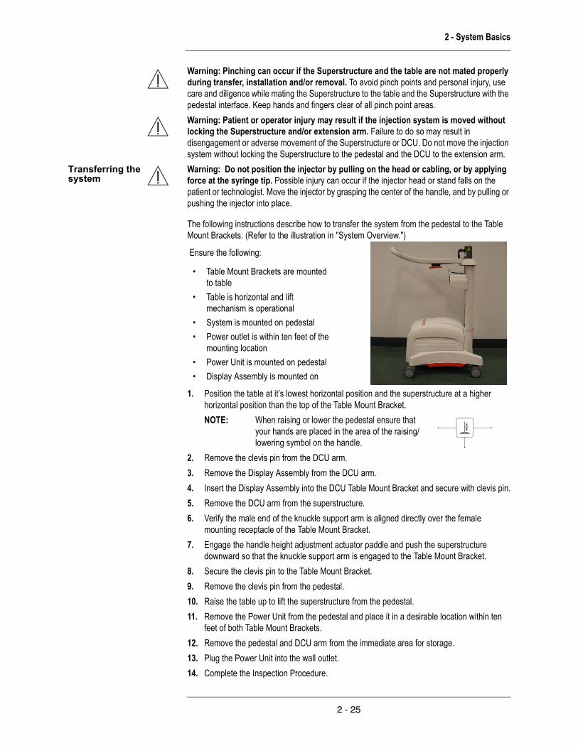
Transferring the system
Warning: Do not position the injector by pulling on the head or cabling, or by applying force at the syringe tip. Possible injury can occur if the injector head or stand falls on the patient or technologist. Move the injector by grasping the center of the handle, and by pulling or pushing the injector into place.
The following instructions describe how to transfer the system from the pedestal to the Table Mount Brackets. (Refer to the illustration in "System Overview.")
Ensure the following:
• Table Mount Brackets are mounted to table
• Table is horizontal and lift mechanism is operational
• System is mounted on pedestal• Power outlet is within ten feet of the
mounting location• Power Unit is mounted on pedestal• Display Assembly is mounted on
1. Position the table at it’s lowest horizontal position and the superstructure at a higher horizontal position than the top of the Table Mount Bracket.NOTE: When raising or lower the pedestal ensure that
your hands are placed in the area of the raising/lowering symbol on the handle.
2. Remove the clevis pin from the DCU arm.3. Remove the Display Assembly from the DCU arm.4. Insert the Display Assembly into the DCU Table Mount Bracket and secure with clevis pin.5. Remove the DCU arm from the superstructure.6. Verify the male end of the knuckle support arm is aligned directly over the female
mounting receptacle of the Table Mount Bracket.7. Engage the handle height adjustment actuator paddle and push the superstructure
downward so that the knuckle support arm is engaged to the Table Mount Bracket.8. Secure the clevis pin to the Table Mount Bracket.9. Remove the clevis pin from the pedestal.10. Raise the table up to lift the superstructure from the pedestal.11. Remove the Power Unit from the pedestal and place it in a desirable location within ten
feet of both Table Mount Brackets.12. Remove the pedestal and DCU arm from the immediate area for storage.13. Plug the Power Unit into the wall outlet.14. Complete the Inspection Procedure.
2 - 25

MEDRAD Avanta Fluid Management Injection System
The following instructions describe how to transfer the system from the Table Mount Brackets to the pedestal. (Refer to the illustration in "System Overview.")
Ensure the following:
• Table is horizontal and lift mechanism is operational• System is mounted on Table Mount Bracket• Power Unit is in a nearby location• Display Assembly is on Table Mount Bracket.
1. Place the pedestal next to the table.2. Place the Power Unit onto the lower portion of the pedestal.3. Lower the pedestal to the lowest position.
NOTE: When raising or lower the pedestal ensure that your hands are placed in the area of the raising/lowering symbol on the handle.
4. Position the table so that the knuckle support arm is at a higher horizontal position than the pedestal.
5. Verify the male end of the knuckle support arm is aligned directly over the female mounting receptacle of the pedestal.
6. Engage the handle height adjustment actuator paddle to raise the pedestal upward so that the knuckle support arm is engaged to the pedestal.
7. Secure the clevis pin to the pedestal.8. Remove the clevis pin from the Table Mount Bracket.9. Lower the table to disengage from the Table Mount Bracket. If lowering the table does not
provide enough clearance, raise the pedestal.10. Place the DCU arm onto the pedestal.11. Remove the clevis pin from the DCU Table Mount Bracket.12. Move the Display Assembly from the Table Mount Bracket to the DCU arm.13. Insert the clevis pin into the DCU arm.14. Plug cables into the Power Unit, if required.
Table Mount Bracket Refer to MEDRAD document number 204195 - MEDRAD Avanta Table Mount Bracket Instructions for Use included in the box for information regarding installation and use.
2 - 26

2 - System Basics
System Safety Information
When power is applied to the system, the system Safety screen appears on the display, and a series of self-diagnostic tests are performed. The Safety screen provides information about safe operation of the injector and potential hazards associated with an injection procedure.
Warning: The Avanta Fluid Management Injection System contains a gross air detection feature which is intended to assist qualified medical professional users/operators during injections to detect gross air contained in the Multi-Patient Disposable Set. As noted throughout this manual, operator vigilance is always required to eliminate potential air hazards during use.
Warning: Before starting any angiographic injection procedure the angiographic team should be trained in the particular angiographic procedures to be performed, and should be familiar with the medical literature related to angiographic procedures and the potential complications and risks versus the benefits of utilizing angiographic fluid injection procedures.
Warning: The safe and effective use of the Avanta Fluid Management Injector System to a large degree depends upon factors under the control of the medical professionals using the system. There is no substitute for a properly trained and vigilant angiographic team. It is important that the operating instructions and user warnings supplied with this Injection System be read, understood and followed.
Touch Screen Calibration
To calibrate the touch screen, simultaneously press both the Brightness up (+) and Brightness down (-) buttons on the back of the DCU. A series of screens with instructions will appear.
Main Screen The Main screen is used during injection protocol programming, syringe refill, arming and injecting. Different options are visible based on the operation being performed and the screen
2 - 27

MEDRAD Avanta Fluid Management Injection System
configuration.
Setup The Configuration screen may be accessed by pressing "Configuration" located on the DCU touch screen display.
The Configuration screen allows the selection of configurable options and preferences, as well as the setting of date and time parameters.
2 - 28

2 - System Basics
The following table identifies the configurable items and their selectable values.
Configurable Item Selectable Value
ISI On, Off
Auto Fill On, Off
Auto Fill Volume 25 mL, 50 mL, 75 mL, 100 mL, 125 mL, 150 mL
Auto Fill Target 1X, 2X, 3X
Refill Alert Off, 25 mL, 50 mL, 75 mL
Test Inject On, Off
Test Inject Rate 1 mL/s, 2 mL/s, 3 mL/s, 4 mL/s, 5 mL/s
Test Inject Volume 1 mL, 2 mL, 3 mL, 4 mL, 5 mL
Rate/Volume Alert On, Off
Footswitch Enabled, Disabled
Language English, Japanese, French, Italian, German, Spanish, Swedish, Chinese, Russian
Automated Saline Flush (ASF) On, Off
Audio Feedback On, Off
Audio Level Loud, Medium, Soft
Max Cases/MPAT 1 - 5 Cases
Syringe Backlight On, Off
Date / Time Date, time
Calibration Reminder Date
Upgrade
Help The Help screen may be accessed by pressing "Help" located on the DCU touch screen
Help Screen
display. Descriptions are included below of each button on the Help screen.
Screen functions RecallTo access protocol memory, touch Recall on the Main screen.Store
2 - 29

MEDRAD Avanta Fluid Management Injection System
To save a protocol, touch Store on the Main screen.SetupTouch Setup on the Main screen to access functions to assist setup of the disposable components.New / EndTouch End in the Case Panel to end the patient case or New to start a patient case.ModeTo select between Fixed and Variable Flow modes, touch Mode on the Main Screen.ArmTo arm in preparation for injection, touch Arm on the Main screen.TestTo arm in preparation for test injection, touch Test on the Main screen.ResetTo reset all parameters associated with the current injection protocol to default values, touch Reset on the Main screen.SetupTo configure the system for particular needs, touch Configuration on the Main screen.
ProgrammingProgramming Help Screen
Service Contact Information
If you require assistance from Medrad’s Service Team, please refer to this operation manual or www.medrad.com, in Japan: http://www.medrad.co.jp/index2.html.
Customer Service Contact MEDRAD’s Customer Service Team if you require assistance to:• Place an order• Check pricing• Request equipment in-service
For contact information, please refer to this operation manual or www.medrad.com, in Japan: http://www.medrad.co.jp/index2.html.
Reset Pressing "Reset" returns all currently programmed parameters to the factory default settings.
The following values are the factory default parameters:
• Flow Rate: 1.0 mL/s• Volume: 1 mL• Rise time: 0.1 s• Pressure limit: 1000 psi
2 - 30

2 - System Basics
• Delay Type: none• Delay Duration: 0
2 - 31

MEDRAD Avanta Fluid Management Injection System
Set Protocol Programming a protocol is initiated at the Main screen.
1. Touch any programmable block, (such as Flow Rate or Volume). The selected block will be black. A numeric keypad and parameter range window appears.
2. Enter the desired Flow Rate, Volume, Pressure Limit and Rise Time (Fixed Rate Injection only).
Warning: Pressure settings must be lower than catheter and other disposables ratings. If a blockage occurs, tubing with a lower pressure rating may be subjected to pressure beyond its capability resulting in a failure. Always verify that the pressure setting on the injector is lower than the maximum ratings of any disposables.
3. Press Enter to lock in the value, press (<<) to edit the value, or Cancel to restore the original value if an error is made.
NOTE: You can also lock in a selected value by touching another parameter.
Warning: Patient injury could result from high flow rate injections. Use extreme care when selecting the flow rate. Before arming the injector, verify that high flow rate injection parameters are correct.
Storing a Protocol To store up to 40 commonly used protocols:
1. Enter the desired parameters on the main screen.
2. Touch Store located in the upper right corner of the Main screen. An alpha-numeric keypad appears with a flashing cursor in the title block.
3. Enter the desired name for the protocol. The name can be up to 20 characters long, including spaces. Use the arrow key to backspace and erase individual characters, or the clear key to erase a string of text.
2 - 32

2 - System Basics
4. Touch Enter when the entry is completed.
NOTE: To exit the Store screen without keeping your changes press Cancel in the upper right corner of the screen to return to the main menu.
Recalling a Protocol To recall a protocol stored in memory:
1. Touch Recall on the upper right corner of the Main Screen.
2. Select a previously stored injection protocol by touching one of the protocol titles on either side of the screen. Upon selection, key parameters of the injection protocol will be displayed in the center of the screen.
NOTE: If a protocol is recalled and then changed, an asterisk appears after the protocol name in the upper left of the screen, and is no longer the stored protocol.
3. Touch OK to return to the main screen.
NOTE: Protocols are ordered starting with the oldest protocol at the top left and continuing with subsequent protocols to the bottom.
2 - 33

MEDRAD Avanta Fluid Management Injection System
Deleting a Protocol To delete a protocol stored in memory:
1. Touch Recall on the upper right corner of the Main Screen.
2. Select a previously stored injection protocol by touching one of the protocol titles on either side of the screen. Upon selection, key parameters of the injection protocol will be displayed in the center of the screen.
3. Touch Delete to permanently erase the protocol from memory.
4. Acknowledge prompt.
2 - 34
3 - Arming and Injecting
3 - Arming and Injecting
Warning: Do not use the system to inject unintended media. The injection system has only been validated for its specified intended use. There may be additional risks associated with use of the system for other purposes due to insufficient performance specifications, or operational safeguards. Contact MEDRAD for additional information.
Minimizing Air Embolization Risks
Operator vigilance and care, coupled with a set procedure, is essential to minimizing the possibility of an air embolism.
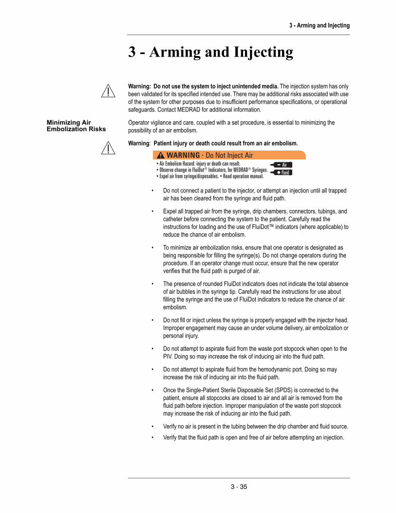
Warning: Patient injury or death could result from an air embolism.
• Do not connect a patient to the injector, or attempt an injection until all trapped air has been cleared from the syringe and fluid path.
• Expel all trapped air from the syringe, drip chambers, connectors, tubings, and catheter before connecting the system to the patient. Carefully read the instructions for loading and the use of FluiDot™ indicators (where applicable) to reduce the chance of air embolism.
• To minimize air embolization risks, ensure that one operator is designated as being responsible for filling the syringe(s). Do not change operators during the procedure. If an operator change must occur, ensure that the new operator verifies that the fluid path is purged of air.
• The presence of rounded FluiDot indicators does not indicate the total absence of air bubbles in the syringe tip. Carefully read the instructions for use about filling the syringe and the use of FluiDot indicators to reduce the chance of air embolism.
• Do not fill or inject unless the syringe is properly engaged with the injector head. Improper engagement may cause an under volume delivery, air embolization or personal injury.
• Do not attempt to aspirate fluid from the waste port stopcock when open to the PIV. Doing so may increase the risk of inducing air into the fluid path.
• Do not attempt to aspirate fluid from the hemodynamic port. Doing so may increase the risk of inducing air into the fluid path.
• Once the Single-Patient Sterile Disposable Set (SPDS) is connected to the patient, ensure all stopcocks are closed to air and all air is removed from the fluid path before injection. Improper manipulation of the waste port stopcock may increase the risk of inducing air into the fluid path.
• Verify no air is present in the tubing between the drip chamber and fluid source. • Verify that the fluid path is open and free of air before attempting an injection.
3 - 35

MEDRAD Avanta Fluid Management Injection System
Caution: Component damage may occur if disposables are not installed properly. Assure all connections are secure. This will help minimize leaks, disconnections, air introduction, and component damage. Do not use tools to over tighten connections or to assist in removal of disposables.
FluiDots are used on the pressure jacket to aid in confirming the presence of fluid in the syringe. FluiDot indicators must be viewed in a properly illuminated environment, with a light source behind the operator, providing enough light to permit easy viewing.
Warning: Patient or operator injury or component damage may occur if an injection is performed without pressure jacket in place. Ensure pressure jacket is in place before performing an injection.
Empty Syringe Filled SyringeGross Air Detection The system disarms if air is detected in the contrast or saline fluid paths of the Multi-Patient
Sterile Disposable Set to minimize the injection of an air bolus to the patient. The user or operator is responsible for making sure that the fluid path is free of air before injecting.
Warning: The Avanta Fluid Management Injection System contains a gross air detection feature which is intended to assist qualified medical professional users/operators during injections to detect gross air contained in the Multi-Patient Disposable Set. As noted throughout this manual, operator vigilance is always required to eliminate potential air hazards during use.
Warning: Before starting any angiographic injection procedure the angiographic team should be trained in the particular angiographic procedures to be performed, and should be familiar with the medical literature related to angiographic procedures and the potential complications and risks versus the benefits of utilizing angiographic fluid injection procedures.
Warning: The safe and effective use of the Avanta Fluid Management Injector System to a large degree depends upon factors under the control of the medical professionals using the system. There is no substitute for a properly trained and vigilant angiographic team. It is important that the operating instructions and user warnings supplied with this Injection System be read, understood and followed.
3 - 36

3 - Arming and Injecting
Powering up the system
To power up the system:
Ensure the following:• The system is properly installed & plugged in (line cord to wall 110v or 220v)
Caution: Damage can occur as a result of incorrect voltage. Verify that the voltage and frequency marked on the serial tag on the back of the Power Unit module matches the voltage and frequency of the electrical outlet.
• Power Unit power is off• Disposables not installed• DCU power switch is off• The system is mounted.
Warning: Injector may disarm or fail to operate upon exposure to high electromagnetic fields that may be generated by radio transmitters or cellular phones, or upon exposure to high levels of electrostatic discharge. Turn off any equipment that could generate an electrostatic discharge.
Warning: Explosion Hazard: Explosion risk may exist if the system is used in the presence of flammable anaesthetic mixtures, and/or flammable agents for disinfection and/or skin cleaning.
Warning: Fire Hazard: To avoid an electrical fire, the injector fuse must be replaced with the appropriate fuse-type by qualified personnel only. Fuses are located on the signal management board (heat maintainers) of the head module and also with the Power Unit module.
Warning: Electrical Shock Hazard: Serious injury or death may result from exposure to hazardous voltages existing within the system. Operator injury could result from work cabling or unit disassembly. To avoid exposure to potentially hazardous voltages, do not disassemble the injection system in any way. Worn cabling also creates voltage hazards. If any worn or damaged cables are detected, do not use the injection system. Contact MEDRAD or your local dealer for service or replacement.
Warning: Electrical Shock Hazard: Operator injury could result from using an extension cord or power adaptor with the system. Plug the injector directly into a properly grounded AC power outlet. Since the injector power cord supplies a safety ground to the unit, using an extension cord will compromise the ground quality and the injector could become unsafe.
1. Turn on the master power switch on the Power Unit. The system responds by illuminating a green light on the Power Unit to indicate that the power is on and properly operating
Power Unit
Back of Power Unit
Power Switch
.
3 - 37

MEDRAD Avanta Fluid Management Injection System
2. Turn the DCU on. The system responds by running self diagnostics.
DCU Power Switch
Back of DCU
Caution: DO NOT hang items on the Display Control Unit, its mounting arm or any other component of the system. Hanging items on the Display Control Unit or other components may result in failure of the mounting system and can result in personal injury and/or equipment damage.
NOTE: If the system does not power up, or a system error is detected such as the one below, disconnect the patient, record the code and contact MEDRAD Service.
3. On the DCU, press "Continue." The system displays the main screen, is powered-up and ready to use.
Emergency Shutdown In the event of an emergency such as a fire, explosion, or electrical shock, the power can be shut down by disconnecting the power cord, or turning off the power switch on the Power Unit.
Patient injury may result from a system malfunction. If a system malfunction occurs, immediately remove unit power by pressing the On/Off switch on the Display Control Unit and disconnecting the unit from the patient. If a fault message is displayed that cannot be corrected, and/or the system is not operating correctly, do not use the injection system. Call MEDRAD or your local dealer for assistance.
Warning: Explosion Hazard: Explosion risk may exist if the system is used in the presence of flammable anaesthetic mixtures, and/or flammable agents for disinfection and/or skin cleaning.
Warning: Fire Hazard: To avoid an electrical fire, the injector fuse must be replaced with the appropriate fuse-type by qualified personnel only. Fuses are located on the signal management board (heat maintainers) of the head module and also with the Power Unit module.
3 - 38
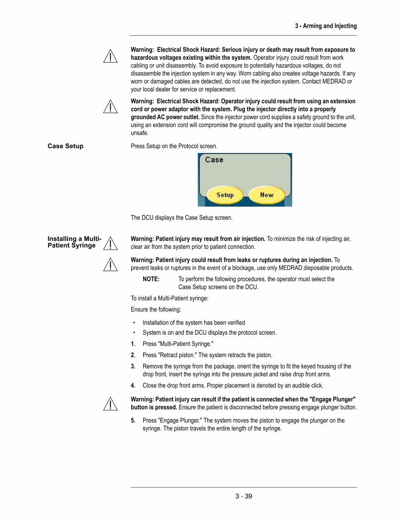
3 - Arming and Injecting
Warning: Electrical Shock Hazard: Serious injury or death may result from exposure to hazardous voltages existing within the system. Operator injury could result from work cabling or unit disassembly. To avoid exposure to potentially hazardous voltages, do not disassemble the injection system in any way. Worn cabling also creates voltage hazards. If any worn or damaged cables are detected, do not use the injection system. Contact MEDRAD or your local dealer for service or replacement.
Warning: Electrical Shock Hazard: Operator injury could result from using an extension cord or power adaptor with the system. Plug the injector directly into a properly grounded AC power outlet. Since the injector power cord supplies a safety ground to the unit, using an extension cord will compromise the ground quality and the injector could become unsafe.
Case Setup Press Setup on the Protocol screen.
The DCU displays the Case Setup screen.
Installing a Multi-Patient Syringe
Warning: Patient injury may result from air injection. To minimize the risk of injecting air, clear air from the system prior to patient connection.
Warning: Patient injury could result from leaks or ruptures during an injection. To prevent leaks or ruptures in the event of a blockage, use only MEDRAD disposable products.
NOTE: To perform the following procedures, the operator must select the Case Setup screens on the DCU.
To install a Multi-Patient syringe:Ensure the following:
• Installation of the system has been verified• System is on and the DCU displays the protocol screen.
1. Press "Multi-Patient Syringe." 2. Press "Retract piston." The system retracts the piston.3. Remove the syringe from the package, orient the syringe to fit the keyed housing of the
drop front, insert the syringe into the pressure jacket and raise drop front arms.4. Close the drop front arms. Proper placement is denoted by an audible click.
Warning: Patient injury can result if the patient is connected when the "Engage Plunger" button is pressed. Ensure the patient is disconnected before pressing engage plunger button.
5. Press "Engage Plunger." The system moves the piston to engage the plunger on the syringe. The piston travels the entire length of the syringe.
3 - 39

MEDRAD Avanta Fluid Management Injection System
Disposable Sets The system permits reuse of certain disposable components for up to and including five patients before disposal.
NOTE: Completely change or flush the disposable set when changing the contrast type.
Warning: Blood can contaminate the multi-patient portion of the disposable set. Ensure that the blood does not appear past the pressure isolation valve in the single patient disposable set.
Warning: Biological contamination can result from reusing disposable items or failure to follow sterile technique during setup or use. Properly discard disposable items after use. If there is any possibility that contamination may have occurred during set-up or use, disassemble and setup a new sterile product.
Warning: Patient injury could result if contrast crystallizes within the multi-patient or single-patient disposable sets. Regularly check the disposable sets for crystallized contrast and discard if present.
Warning: Biological contamination can result from reusing disposable items or by not following aseptic technique. Discard the DCU and Hand Controller sterile sheath after every use. Replace sterile sheath if damaged.
Warning: Patient injury may result if the injector head or pedestal is moved while the catheter is connected to the patient. Ensure the catheter is disconnected from the patient before moving the injector.
Warning: Storage of filled syringes can promote bacterial growth. MEDRAD syringes are designed to be filled just prior to the procedure. Discard unused filled syringes.
Caution: Use of methyl alcohol will degrade the integrity of the disposable sets. Do not use methyl alcohol on disposable sets.
Install Multi-Patient Disposable Sets
Refer to MEDRAD document 205064 - MEDRAD Avanta Sterile Disposable Sets Instructions for Use.
The Multi-Patient Sterile Disposable Set (MPDS) consists of the following items:• Vented Contrast Spike • Contrast Drip Chamber• Low Pressure Contrast Tube (LPCT)• High Pressure Contrast Tube (HPCT)• Contrast Flow Control Valve (CFCV)• Second High Pressure Contrast Tube with
male luer connector• Saline Spike• Saline Drip Chamber• Low Pressure Saline Tube (LPST)• Post Drip Chamber Saline Tube with female
Luer connector• 150 mL Multi-Patient Syringe
3 - 40

3 - Arming and Injecting
Vented Contrast Spike
Contrast Drip Chamber
LPCT
HPCT
CFCV Mechanism
2nd HPCT
Saline Spike
Saline Drip Chamber
LPST
Post Drip Chamber Saline TubePeg
Syringe
Contrast Flow Control Valve Mechanism
(CFCV)
The contrast flow control valve mechanism (CFCV) allows the path of the contrast to change. The mechanism has three positions: inject, fill and closed.
Drip Chambers The drip chambers are clear, flexible reservoirs for saline and contrast that help initiate the filling of the fluid pathway.
NOTE: Ensure that the drip chambers are filled completely and snapped fully in position before use.
Warning: Patient injury or death could result from an air embolism.
• Do not connect a patient to the injector, or attempt an injection until all trapped air has been cleared from the syringe and fluid path.
• Expel all trapped air from the syringe, drip chambers, connectors, tubings, and catheter before connecting the system to the patient. Carefully read the instructions for loading and the use of FluiDot™ indicators (where applicable) to reduce the chance of air embolism.
• Verify no air is present in the tubing between the drip chamber and fluid source. • Verify that the fluid path is open and free of air before attempting an injection.
NOTE: To perform the following procedures, the operator must select the Case Setup screens on the DCU.
3 - 41
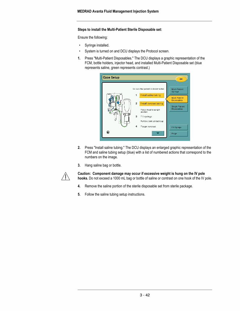
MEDRAD Avanta Fluid Management Injection System
Steps to install the Multi-Patient Sterile Disposable set:
Ensure the following:
• Syringe installed. • System is turned on and DCU displays the Protocol screen.
1. Press "Multi-Patient Disposables." The DCU displays a graphic representation of the FCM, bottle holders, injector head, and installed Multi-Patient Disposable set (blue represents saline, green represents contrast.)
2. Press "Install saline tubing." The DCU displays an enlarged graphic representation of the FCM and saline tubing setup (blue) with a list of numbered actions that correspond to the numbers on the image.
3. Hang saline bag or bottle.
Caution: Component damage may occur if excessive weight is hung on the IV pole hooks. Do not exceed a 1000 mL bag or bottle of saline or contrast on one hook of the IV pole.
4. Remove the saline portion of the sterile disposable set from sterile package.
5. Follow the saline tubing setup instructions.
3 - 42

3 - Arming and Injecting
Saline Tubing Setup
1. Install the saline drip chamber into the keyed interface and press firmly to engage.
2. Open the Peristaltic Pump door, route the tubing through the pump, and close the door.
Warning: Operator injury may occur if Peristaltic Pump is operating with the door open. A pinch point exists due to rotating mechanical parts. Do not operate Peristaltic Pump with the door open.
3. Route tubing around peg.
4. Insert the tubing into the gross air detector and close door.
On the touch screen, select the down arrow.
5. Spike the saline bag or bottle.
Warning: Patient or operator injury may result from mishandling of the sharp spike. Use care in handling and inserting the spike into the contrast bottle and the saline bag or bottle.
6. Fill the saline drip chamber completely by repeatedly squeezing and releasing. Remove the drip chamber to aid in expelling air and replace when completed.
3 - 43

MEDRAD Avanta Fluid Management Injection System
Warning: Patient injury or death could result from an air embolism.
• Do not connect a patient to the injector, or attempt an injection until all trapped air has been cleared from the syringe and fluid path.
• Verify no air is present in the tubing between the drip chamber and fluid source. • Verify that the fluid path is open and free of air before attempting an injection.
7. Press "Complete." The DCU displays a graphic representation of the FCM, bottle holders, injector head, and installed Multi-Patient Disposable set (blue represents saline, green represents contrast.)
8. Press "Install contrast tubing." The DCU displays an enlarged graphic representation of the FCM and contrast tubing setup (green) with a list of numbered actions that correspond to the numbers on the image.
9. Hang the contrast bag or bottle.
Warning: For best result, all contrast media should be used in accordance with the manufacturer’s indication for use.
10. Follow the contrast tubing setup instructions.
Warning: Biological contamination can result from reusing disposable items or failure to follow sterile technique during setup or use. Properly discard disposable items after use. If there is any possibility that contamination may have occurred during set-up or use, disassemble and setup a new sterile product.
Blood can contaminate the multi-patient portion of the disposable set. Ensure that blood does not appear past the pressure isolation valve in the single patient disposable set.
Biological contamination can result from reusing disposable items or failure to follow sterile technique during setup or use. Properly discard disposable items after use. If there is any possibility that contamination may have occurred during set-up or use, disassemble and setup a new sterile product.
Patient injury could result if contrast crystallizes within the multi-patient or single- patient disposable sets. Regularly check the disposable sets for crystallized contrast and discard if present.
3 - 44

3 - Arming and Injecting
Contrast Tubing Setup
1. Install contrast drip chamber.
2. Connect the tubing to the syringe.
3. Install the stopcock into the CFCV mechanism.
4. Insert the tubing into the gross air detector and close door.
On the touch screen, select the down arrow.
5. Spike the contrast bottle or bag.
Warning: Patient injury or death could result from an air embolism.
• Do not connect a patient to the injector, or attempt an injection until all trapped air has been cleared from the syringe and fluid path.
• Verify no air is present in the tubing between the drip chamber and fluid source. • Verify that the fluid path is open and free of air before attempting an injection.
3 - 45
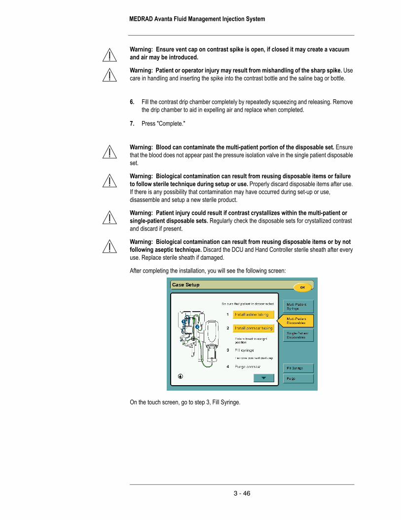
MEDRAD Avanta Fluid Management Injection System
Warning: Ensure vent cap on contrast spike is open, if closed it may create a vacuum and air may be introduced.
Warning: Patient or operator injury may result from mishandling of the sharp spike. Use care in handling and inserting the spike into the contrast bottle and the saline bag or bottle.
6. Fill the contrast drip chamber completely by repeatedly squeezing and releasing. Remove the drip chamber to aid in expelling air and replace when completed.
7. Press "Complete."
Warning: Blood can contaminate the multi-patient portion of the disposable set. Ensure that the blood does not appear past the pressure isolation valve in the single patient disposable set.
Warning: Biological contamination can result from reusing disposable items or failure to follow sterile technique during setup or use. Properly discard disposable items after use. If there is any possibility that contamination may have occurred during set-up or use, disassemble and setup a new sterile product.
Warning: Patient injury could result if contrast crystallizes within the multi-patient or single-patient disposable sets. Regularly check the disposable sets for crystallized contrast and discard if present.
Warning: Biological contamination can result from reusing disposable items or by not following aseptic technique. Discard the DCU and Hand Controller sterile sheath after every use. Replace sterile sheath if damaged.
After completing the installation, you will see the following screen:
On the touch screen, go to step 3, Fill Syringe.
3 - 46

3 - Arming and Injecting
Fill Syringe To fill the syringe for the first time, the piston must engage the plunger and must be fully forward.
Warning: Inadvertent aspiration can occur if the Multi-Patient disposable contrast tubing set is kinked or blocked during a syringe fill process. Verify multi-patient contrast tubing is free of kinks before attempting to fill the syringe.
NOTE: To minimize the chance of aspiration caused by a trapped vacuum, the system will prompt the operator when a vacuum is detected in the syringe. If a vacuum is detected, the operator will be required to disconnect from the patient, remove SPDS and perform a contrast purge to relieve the vacuum and purge any potential trapped air from the system disposables.
Ensure the following:
• A new Multi-Patient Sterile Disposable set has just been installed.• The syringe plunger is engaged and in full forward position.• Contrast tubing is straight and free of kinks.
1. Rotate the head into the upright position so that air can escape from the syringe. The syringe is now ready to be filled for the first time.
Warning: Do not position the injector by pulling on the head or cabling, or by applying force at the syringe tip. Possible injury can occur if the injector head or stand falls on the patient or technologist. Move the injector by grasping the center of the handle, and by pulling or pushing the injector into place.
Press "Fill Syringe."
3 - 47

MEDRAD Avanta Fluid Management Injection System
2. Enter the desired amount of contrast to fill the syringe.
3. Press "Fill." A graphic representation of the syringe filling is displayed on the screen.
After the syringe is filled, you will see the following screen:
4. Remove the contrast dustcap. On the touch screen, go to step 4, Purge contrast.
Purge Contrast To purge air out of contrast line of the Multi-Patient Sterile Disposable set:
Ensure the following:
• The Multi-Patient Sterile Disposable set has just been installed, the syringe has been adequately filled with contrast (piston is fully or partially retracted), and the syringe is in the upright position.
• The Single-Patient Sterile Disposable set is not installed.
Warning: Patient injury can result if the patient is connected during any contrast or saline purge. Ensure the patient is disconnected before any purge.
Warning: Patient injury or death could result from an air embolism.
3 - 48

3 - Arming and Injecting
• Do not connect a patient to the injector, or attempt an injection until all trapped air has been cleared from the syringe and fluid path.
5. Press "Purge." A graphic representation of available purge options are displayed on the screen.
6. Initiate Contrast purge.
7. Catch the discharged fluid in a suitable container and tap disposable connection points and pressure jacket to remove air.
8. Press "Stop" when all visible air has been discharged.
NOTE: The system stops the purge operation automatically when 7 mL of fluid/air is expelled.
9. Repeat steps above as needed, until all air is purged.
10. Press Complete.
After the contrast line of the tubing is purged, select the down arrow on the touch screen. You will see the following screen:
11. Rotate the head downward.
Warning: Do not position the injector by pulling on the head or cabling, or by applying force at the syringe tip. Possible injury can occur if the injector head or stand falls on the patient or technologist. Move the injector by grasping the center of the handle, and by pulling or
3 - 49
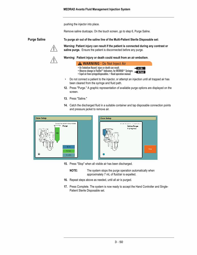
MEDRAD Avanta Fluid Management Injection System
pushing the injector into place.
Remove saline dustcaps. On the touch screen, go to step 6, Purge Saline.
Purge Saline To purge air out of the saline line of the Multi-Patient Sterile Disposable set:
Warning: Patient injury can result if the patient is connected during any contrast or saline purge. Ensure the patient is disconnected before any purge.
Warning: Patient injury or death could result from an air embolism.
• Do not connect a patient to the injector, or attempt an injection until all trapped air has been cleared from the syringe and fluid path.
12. Press "Purge." A graphic representation of available purge options are displayed on the screen.
13. Press "Saline."
14. Catch the discharged fluid in a suitable container and tap disposable connection points and pressure jacket to remove air.
15. Press "Stop" when all visible air has been discharged.
NOTE: The system stops the purge operation automatically when approximately 7 mL of fluid/air is expelled.
16. Repeat steps above as needed, until all air is purged.
17. Press Complete. The system is now ready to accept the Hand Controller and Single-Patient Sterile Disposable set.
3 - 50

3 - Arming and Injecting
After the saline line of the tubing is purged, you will see the following screen:
On the touch screen, go to step 7, Attach hand controller, if applicable.
Install Hand Controller:
1. Attach the Hand Controller to the port at the bottom of the FCM and maintain sterility, if applicable.
2. Place the Hand Controller sterile sheath over the Hand Controller, if applicable.
NOTE: If the Hand Controller is used without the optional Hand Controller Sterile Sheath, discard the Hand Controller after each patient.
3 - 51

MEDRAD Avanta Fluid Management Injection System
Install Single-Patient Disposable Set
The Single-Patient Sterile Disposable Set (SPDS) consists of the following items, all attached, to form a single complete element:
• Low Pressure Saline tube with male Luer connector
• High Pressure Contrast Tube with female Luer connector
• Pressure Isolation Valve (PIV) / Hemodynamic pressure monitoring Port (B)
• Stopcock for waste port (C)• Rotating luer (A).
Rotating luer PIV
Stopcock
A BC
NOTE: To perform the following procedures, the operator must select the Case Setup screens on the DCU.
Steps to install the Single-Patient Sterile Disposable set:
Refer to MEDRAD document 205064 - MEDRAD Avanta Sterile Disposable Sets Instructions for Use.
Ensure the following:
• The Multi-Patient Sterile Disposable set is installed on the system.• Dustcaps are in place.• The system is in a state that it is ready to accept the Single-Patient Sterile Disposable set.• The DCU sterile cover is on the DCU (optional.)
3 - 52

3 - Arming and Injecting
Warning: Patient injury or death could result from an air embolism.
• Do not connect a patient to the injector, or attempt an injection until all trapped air has been cleared from the syringe and fluid path.
• Expel all trapped air from the syringe, drip chambers, connectors, tubings, and catheter before connecting the system to the patient. Carefully read the instructions for loading and the use of FluiDot™ indicators (where applicable) to reduce the chance of air embolism.
• To minimize air embolization risks, ensure that one operator is designated as being responsible for filling the syringe(s). Do not change operators during the procedure. If an operator change must occur, ensure that the new operator verifies that the fluid path is purged of air.
• The presence of rounded FluiDot indicators does not indicate the total absence of air bubbles in the syringe tip. Carefully read the instructions for use about filling the syringe and the use of FluiDot indicators to reduce the chance of air embolism.
• Do not fill or inject unless the syringe is properly engaged with the injector head. Improper engagement may cause an under volume delivery, air embolization or personal injury.
• Do not attempt to aspirate fluid from the waste port stopcock when open to the PIV. Doing so may increase the risk of inducing air into the fluid path.
• Do not attempt to aspirate fluid from the hemodynamic port. Doing so may increase the risk of inducing air into the fluid path.
• Once the Single-Patient Sterile Disposable Set (SPDS) is connected to the patient, ensure all stopcocks are closed to air and all air is removed from the fluid path before injection. Improper manipulation of the waste port stopcock may increase the risk of inducing air into the fluid path.
• Verify no air is present in the tubing between the drip chamber and fluid source. • Verify that the fluid path is open and free of air before attempting an injection.
NOTE: The Single-Patient Sterile Disposable set must be replaced after each patient use.
Press "Single-Patient Disposables." The following screen appears.
3 - 53

MEDRAD Avanta Fluid Management Injection System
1. Remove all dustcaps.
2. Connect the SPDS saline tube to MPDS saline tube.
3. Connect the SPDS contrast tube to MPDS contrast tube.
On the touch screen, select the down arrow.
Purge Contrast To purge air out of contrast line of the Single-Patient Sterile Disposable Set:
Warning: Patient injury can result if the patient is connected during any contrast or saline purge. Ensure the patient is disconnected before any purge.
Warning: Patient injury or death could result from an air embolism.
• Do not connect a patient to the injector, or attempt an injection until all trapped air has been cleared from the syringe and fluid path.
4. Verify that the waste port stopcock is closed to the PIV.
5. Hold the SPDS horizontal with waste port facing down.
6. Initiate contrast purge, tap SPDS to MPDS contrast connection point to remove air.
3 - 54

3 - Arming and Injecting
On the touch screen, select the down arrow.
Purge Saline To purge air out of saline line of the Single-Patient Sterile Disposable Set:
Warning: Patient injury can result if the patient is connected during any contrast or saline purge. Ensure the patient is disconnected before any purge.
Warning: Patient injury or death could result from an air embolism.
• Do not connect a patient to the injector, or attempt an injection until all trapped air has been cleared from the syringe and fluid path.
7. Verify that the waste port stopcock is closed to the PIV.
8. Initiate saline purge, tap SPDS to MPDS saline connection point to remove air.
9. Recap PIV hemodynamic port (if applicable, attach hemodynamic transducer, initiate saline purge, zero transducer, and close transducer stopcock).
On the touch screen, select the down arrow.
3 - 55
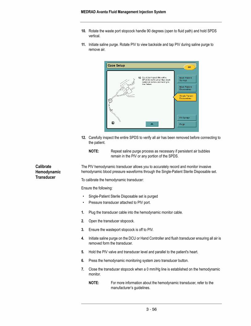
MEDRAD Avanta Fluid Management Injection System
10. Rotate the waste port stopcock handle 90 degrees (open to fluid path) and hold SPDS vertical.
11. Initiate saline purge. Rotate PIV to view backside and tap PIV during saline purge to remove air.
12. Carefully inspect the entire SPDS to verify all air has been removed before connecting to the patient.
NOTE: Repeat saline purge process as necessary if persistent air bubbles remain in the PIV or any portion of the SPDS.
Calibrate Hemodynamic Transducer
The PIV hemodynamic transducer allows you to accurately record and monitor invasive hemodynamic blood pressure waveforms through the Single-Patient Sterile Disposable set.
To calibrate the hemodynamic transducer:
Ensure the following:
• Single-Patient Sterile Disposable set is purged• Pressure transducer attached to PIV port.
1. Plug the transducer cable into the hemodynamic monitor cable.
2. Open the transducer stopcock.
3. Ensure the wasteport stopcock is off to PIV.
4. Initiate saline purge on the DCU or Hand Controller and flush transducer ensuring all air is removed form the transducer.
5. Hold the PIV valve and transducer level and parallel to the patient's heart.
6. Press the hemodynamic monitoring system zero transducer button.
7. Close the transducer stopcock when a 0 mm/Hg line is established on the hemodynamic monitor.
NOTE: For more information about the hemodynamic transducer, refer to the manufacturer’s guidelines.
3 - 56

3 - Arming and Injecting
Refilling a Syringe The system can be configured to fill a syringe either manually or automatically. The system does not allow contrast injection while filling and returns to previous state when the fill completes. Saline flush is available while the syringe is filling. When Auto Fill is enabled, you can select Auto Fill volumes from 25 -150 mL, in increments of 25. You can also configure an auto fill volume threshold as a multiple of programmed volume on the main protocol screen (e.g. 2x multiplier on a 10 mL injection will refill when volume drops below 20mL). Auto Fill occurs when the volume in the syringe falls below the user configured threshold. You can enter any desired fill volume when in the manual fill mode.
The Refill Alert can be configured to issue an audible indication when a preset volume is remaining.
Warning: Inadvertent aspiration can occur if the Multi-Patient disposable contrast tubing set is kinked or blocked during a syringe fill process. Verify multi-patient contrast tubing is free of kinks before attempting to fill the syringe.
NOTE: To minimize the chance of aspiration caused by a trapped vacuum, the system will prompt the operator when a vacuum is detected in the syringe. If a vacuum is detected, the operator will be required to disconnect from the patient, remove SPDS and perform a contrast purge to relieve the vacuum and purge any potential trapped air from the system disposables.
Auto Fill The syringe will automatically fill when the volume in the syringe falls below the user configured threshold.
At the Main screen, a graphical representation of the volume in the syringe is displayed based upon the piston position. The system proceeds until the programmed fill volume is achieved.
Auto Fill will STOP if:
• The programmed fill volume has been achieved• The fluid level sensor shows no fluid • The operator stops the Auto Fill by pressing Stop or the hand controller plunger.
Auto Fill can also be initiated by pressing the Fill button on the Main screen.
Manual Fill A manual fill can occur after the initial fill and when the Auto Fill function is configured off. You can initiate a manual fill at any time the system is disarmed. If you do not initiate a manual fill and program a fluid injection protocol that requires more contrast than what is available in the syringe, the system will prompt you to fill prior to achieving the armed state or ask you to continue with remaining volume. You can program fill volumes from 1 - 150 mL in increments of 1 mL.
To fill a syringe ensure the following:
• Installation of the system has been verified and includes all components of the Multi-Patient Sterile Disposable Set.
• Syringe is engaged• Contrast volume is available• Single-Patient Sterile Disposable set may or may not be installed• System is not armed or injecting• No tubing kinks.
At the Setup screen, press "Fill Syringe." The DCU displays a graphical representation of the volume in the syringe based on the piston position. Enter the desired volume and press "Fill." The system proceeds until the total remaining volume in the syringe has reached the
3 - 57

MEDRAD Avanta Fluid Management Injection System
programmed volume or contrast volume is depleted from the bottle, whichever occurs first.
3 - 58

3 - Arming and Injecting
Arming the injector Prior to injecting, the system requires you to place the system in a pre-injection (armed) condition during which the system determines if it is appropriate and safe to allow an injection. The system indicates it is in the armed state by an illuminated white light on the injector head. The system can be configured to issue an alert when armed for a high flow rate (greater than 10 mL/s) and/or high volume (greater than or equal to 20 mL) injection.
Variable Mode In the variable rate injection mode, the injector automatically re-arms after each injection.
Fixed Mode In the fixed rate injection mode, a single or multi-armed state can be selected.
When the system is armed for a single injection the injector disarms when the injection is complete. When multi-arm is selected, the injector automatically re-arms after each injection to allow the injection protocol to be repeated.
When the system is armed and not injecting, it will disarm under the following conditions:
• "Disarm" is pressed on the touch screen.• The system has determined that the injection cannot proceed safely (e.g. system
sensor(s) feedback reporting a hazard condition)• The system is idle for longer than 30 minutes.
Warning: Patient injury or death could result from an air embolism.
• Verify that the fluid path is open and free of air before attempting an injection.
Warning: Patient injury could result from high flow rate injections. Use extreme care when selecting the flow rate. Before arming the injector, verify that high flow rate injection parameters are correct.
3 - 59

MEDRAD Avanta Fluid Management Injection System
When injecting, the system returns to a disarmed state under the following conditions:
• Contact at any location on the touch screen• When the system has determined that the injection cannot proceed safely (e.g. system
sensor(s) feedback reporting a hazard condition)• Overpressure condition• When disposables have been removed from system• At the end of a Fixed Rate injection.
NOTE: Always verify the protocol prior to arming the injector or initiating an injection.
Check for Air Warning: Patient injury or death could result from an air embolism.
Warning: The Avanta Fluid Management Injection System contains a gross air detection feature which is intended to assist qualified medical professional users/operators during injections to detect gross air contained in the Multi-Patient Disposable Set. As noted throughout this manual, operator vigilance is always required to eliminate potential air hazards during use.
Warning: Before starting any angiographic injection procedure the angiographic team should be trained in the particular angiographic procedures to be performed, and should be familiar with the medical literature related to angiographic procedures and the potential complications and risks versus the benefits of utilizing angiographic fluid injection procedures.
Warning: The safe and effective use of the Avanta Fluid Management Injector System to a large degree depends upon factors under the control of the medical professionals using the system. There is no substitute for a properly trained and vigilant angiographic team. It is important that the operating instructions and user warnings supplied with this Injection System be read, understood and followed.
The system prompts the operator to check that air has been purged from the disposable set before an injection is started. Further injector operation that could potentially introduce air into the disposable set alerts the operator to reconfirm that air has been purged via a sentinal message on the main screen. Successful purging of air from the disposable set is the responsibility of the operator. The operator must verify that all air is successfully purged from the disposable set before contrast or saline is injected into the patient.
3 - 60
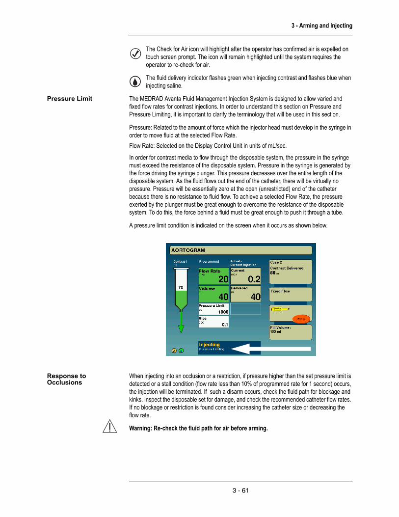
3 - Arming and Injecting
The Check for Air icon will highlight after the operator has confirmed air is expelled on touch screen prompt. The icon will remain highlighted until the system requires the operator to re-check for air.
The fluid delivery indicator flashes green when injecting contrast and flashes blue when injecting saline.
Pressure Limit The MEDRAD Avanta Fluid Management Injection System is designed to allow varied and fixed flow rates for contrast injections. In order to understand this section on Pressure and Pressure Limiting, it is important to clarify the terminology that will be used in this section.
Pressure: Related to the amount of force which the injector head must develop in the syringe in order to move fluid at the selected Flow Rate.Flow Rate: Selected on the Display Control Unit in units of mL/sec.
In order for contrast media to flow through the disposable system, the pressure in the syringe must exceed the resistance of the disposable system. Pressure in the syringe is generated by the force driving the syringe plunger. This pressure decreases over the entire length of the disposable system. As the fluid flows out the end of the catheter, there will be virtually no pressure. Pressure will be essentially zero at the open (unrestricted) end of the catheter because there is no resistance to fluid flow. To achieve a selected Flow Rate, the pressure exerted by the plunger must be great enough to overcome the resistance of the disposable system. To do this, the force behind a fluid must be great enough to push it through a tube.
A pressure limit condition is indicated on the screen when it occurs as shown below.
Response to Occlusions
When injecting into an occlusion or a restriction, if pressure higher than the set pressure limit is detected or a stall condition (flow rate less than 10% of programmed rate for 1 second) occurs, the injection will be terminated. If such a disarm occurs, check the fluid path for blockage and kinks. Inspect the disposable set for damage, and check the recommended catheter flow rates. If no blockage or restriction is found consider increasing the catheter size or decreasing the flow rate.
Warning: Re-check the fluid path for air before arming.
3 - 61

MEDRAD Avanta Fluid Management Injection System
Warning: Patient injury or death could result from an air embolism.
• Do not connect a patient to the injector, or attempt an injection until all trapped air has been cleared from the syringe and fluid path.
• Verify no air is present in the tubing between the drip chamber and fluid source. • Verify that the fluid path is open and free of air before attempting an injection.
Warning: Replace the disposable set following a high pressure disarm condition.
Volume and Rate Protection
The following means are provided to protect against over and under volume or rate conditions:
• Warnings displayed on the Safety screen remind the operator to check the programmed injection parameters prior to the system being armed.
• An on-screen indication of insufficient volume is provided whenever the total volume programmed to be delivered is greater than the amount of fluid in the syringe.
Injection monitoring is performed to detect over rate or over volume conditions due to system faults. If either of these conditions is detected, the injection will be stopped.
Saline injection Saline Flush can be initiated via the Hand Controller or graphical user interface. The system injects saline at a rate of 1.25 +/-.25 mL/sec. Saline can be delivered using the saline button located on the Hand Controller. During a procedure saline can be requested and injected at anytime except when contrast injection is being performed.
Saline can also be delivered by activating an Automated Saline Flush (ASF) at the main protocol screen on the graphical user interface. ASF is a configurable feature that can be turned on or off via the configurations screen. The ASF feature can be programmed to deliver saline during idle periods when contrast is not being delivered. ASF is not available when the system is filling the syringe, armed for a contrast injection, or when contrast is actively being delivered. ASF rate can be programmed on the main protocol screen with a range of 0.1 - 20 ml/min in 0.1 ml/min increments. An injection duration can also be programmed with a range of 1 - 20 min(s) in 1 minute increments. If the combination of rate and duration would cause the delivery of more than 200 ml of fluid, the injector will stop ASF when 200 ml have been delivered and notify the user.
Automated Saline Flush will stop if:
• The programmed protocol has been delivered • A maximum allowable volume of 200 ml has been reached • The saline fluid level sensor shows no fluid • The operator stops Automated Saline Flush by pressing Stop or the hand controller saline
button.
3 - 62

3 - Arming and Injecting
Fixed Rate Injection A fixed rate injection can be initiated by the Hand Controller or the Footswitch (option) and ranges from 1 - 45 mL/sec in increments of 1 mL/sec with the rate being constant throughout the injection. Fixed rate is intended for those procedures where variable rate is not desired and higher flow rates may be needed. You can program acceleration of fluid delivery through the input of rise time for fixed rate injections as follows: 0.0 to 9.9 seconds.
Warning: Patient injury could result from high flow rate injections. Use extreme care when selecting the flow rate. Before arming the injector, verify that high flow rate injection parameters are correct.
To initiate a fixed rate injection, ensure the following:
• Multi-Patient Sterile Disposable set & Single-Patient Sterile Disposable set installed• System purged of air
Warning: Patient injury or death could result from an air embolism.
3 - 63

MEDRAD Avanta Fluid Management Injection System
Warning: Patient injury can result if the patient is connected during any contrast or saline purge. Ensure the patient is disconnected before any purge.
• Procedure parameters programmed• Single-Patient Sterile Disposable set connected to catheter• System armed and ready to inject.
To begin the injection, depress the plunger on Hand Controller or depress the Footswitch (option). The piston moves forward at the programmed rate (rate entered into the flow rate box on the set up screen). Contrast flows until you release the plunger, step off the Footswitch (option), or the programmed volume is injected.
Variable Rate Injection A variable rate injection can be initiated by the Hand Controller and ranges from 1 - 10 mL/sec in increments of 0.1 mL/sec. You can modulate variable rate input as the injection is being performed. Variable rate is intended for use in those procedures where low volumes are injected and variable rate control is desired. The system has an option for receiving audible feedback when using the Hand Controller. The feedback indicates the flow rate.
To initiate a variable rate injection, ensure the following:
• Multi-Patient Sterile Disposable set & Single-Patient Sterile Disposable set installed• System purged of air
Warning: Patient injury or death could result from an air embolism.
Warning: Patient injury can result if the patient is connected during any contrast or saline purge. Ensure the patient is disconnected before any purge.
• Procedure parameters programmed• Single-Patient Sterile Disposable set connected to catheter• System armed and ready to inject.
Depress the plunger on the Hand Controller. When in the variable rate injection mode, the flow rate increases incrementally as the Hand Controller is depressed, and decreases as the Hand Controller is released. Contrast flows until you release the plunger, or the programmed volume is injected. The system remains armed in preparation for the next variable rate injection.
3 - 64

3 - Arming and Injecting
Injection Complete The system indicates the normal completion of an injection by:
• Displaying an injection completion indication on the display control unit• Generating an audible injection complete tone at the display control unit.
NOTE: When variable rate and multi-arm fixed flow are selected, only the tone is heard whenever the injector returns to the arm state; the injection complete indication is not displayed.
End Case Before removing the disposables, press "End" and verify that the case has ended.
If five cases have not been completed, press "New" case on the Case Setup screen.
If five cases (configurable) are completed, refer to "Installing a Multi-Patient Syringe" and "Install Multi-Patient Disposable Sets" in section 3 to start a new case.
NOTE: Case numbers are noted in the counter.
Remove Single-Patient Disposable Set
Remove contrast and saline multi-guard luers from Multi-Patient Sterile Disposable set. Attach sterile dustcaps to MPDS when applicable.
3 - 65

MEDRAD Avanta Fluid Management Injection System
Remove Multi-Patient Disposable Set
To remove the Multi-Patient Sterile Disposable set:
Saline
1. Open gross air detector doors.2. Open peristaltic pump door and remove saline tube.3. Remove drip chamber.4. Pull spike from saline bag and discard.
Warning: Patient or operator injury may result from mishandling of the sharp spike. Use care in handling and inserting the spike into the contrast bottle and the saline bag or bottle.
Contrast
1. Open gross air detector doors.2. Release drop front arms and remove syringe.3. Remove stopcock.4. Remove drip chamber.5. Pull vented spike from contrast bottle and discard.
Warning: Patient or operator injury may result from mishandling of the sharp spike. Use care in handling and inserting the spike into the contrast bottle and the saline bag or bottle.
Warning: Storage of filled syringes can promote bacterial growth. MEDRAD syringes are designed to be filled just prior to the procedure. Discard unused filled syringes.
Warning: All contrast media should be used in accordance with the manufacturer's indication for use.
Warning: Patient injury could result if contrast crystallizes within the multi-patient or single-patient disposable sets. Regularly check the disposable sets for crystallized contrast and discard if present.
3 - 66
4 - ISI Option
4 - ISI Option
Introduction The MEDRAD Avanta Imaging System Interface (ISI) is an accessory that allows the MEDRAD Avanta Fluid Management Injection System to interface with an imaging system. This feature provides for synchronization of the injection and the x-ray exposure.
Read all the information contained in this manual. Understanding this information will assist you in properly operating the MEDRAD Avanta ISI accessory.
Intended Use The MEDRAD Avanta ISI is intended for the specific purpose of allowing the MEDRAD Avanta Fluid Management Injection System to interface with an imaging system.
Important Safety Notice
The MEDRAD Avanta ISI is intended to be used by medical professionals with adequate training and experience in the operation of the MEDRAD Avanta Fluid Management Injection System and angiographic procedures and techniques.
Warnings Use of non-MEDRAD supplied accessories (power cable, ISI cable) and replacement parts for internal components may result in increased emissions or decreased immunity for the equipment or system. Use only MEDRAD supplied accessories and replacement parts.
Patient injury could result from a system malfunction. If a system malfunction occurs, immediately remove unit power by pressing the power switch and disconnect the unit from the patient. If a fault message is displayed that cannot be corrected, and/or the system is not operating correctly, do not use the injection system. Call MEDRAD or your local dealer for assistance.
Do not disassemble the Power Unit assembly. No user serviceable parts exist within the assembly.
Shock hazard: Patient injury could result from worn cabling or unit disassembly. To avoid exposure to potentially hazardous voltages, do not disassemble the MEDRAD Avanta ISI in any way. Worn cabling also creates hazards. If any worn or damaged cables are detected, do not use the ISI option. Contact MEDRAD or your local dealer for service or replacement.
Damaged cables may cause electrical shock. Do not use the ISI option if cables are damaged. Contact MEDRAD or your local dealer for service or replacement.
Patient or operator injury may result if damaged components are used. Do not use damaged components. Visually inspect all components before use.
Cautions System damage may occur if voltage is applied to ISI Pins 5, 6, 7, 8, or 9 in a Universal configuration or to ISI Pins 2, 3, 4, 5, 6, 8, 9, 10 in a Special/Siemens configuration. Only connect these pins to isolated switch or relay contacts from the imaging system.
MEDRAD can only be responsible for proper injector and imaging system interaction if they are configured exactly as specified. The injector and imaging system will operate as described in this section only if the MEDRAD Avanta ISI is installed according to this manual and the imaging system is capable of accepting these signals via the interface.
Improper installation of the MEDRAD Avanta ISI may cause it to fail. Installation must be completed by properly trained personnel. Call MEDRAD or your local dealer for assistance.
4 - 67
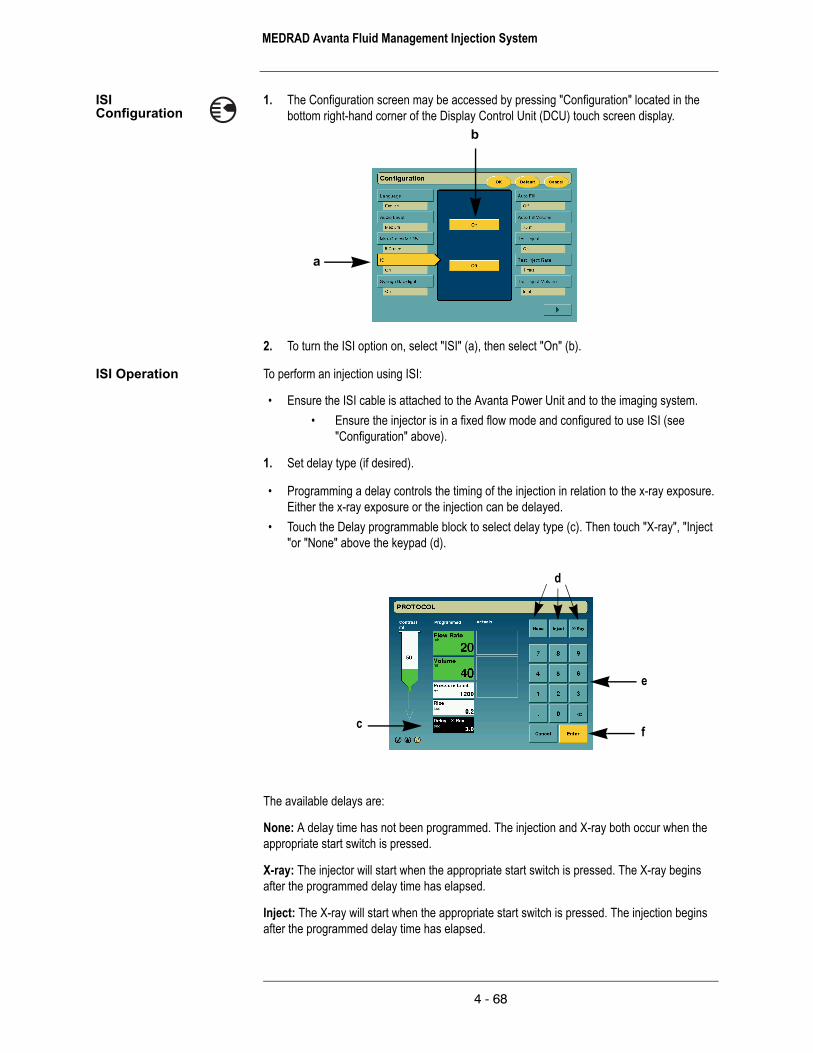
MEDRAD Avanta Fluid Management Injection System
ISI Configuration
1. The Configuration screen may be accessed by pressing "Configuration" located in the bottom right-hand corner of the Display Control Unit (DCU) touch screen display.
a
b
2. To turn the ISI option on, select "ISI" (a), then select "On" (b).
ISI Operation To perform an injection using ISI:
• Ensure the ISI cable is attached to the Avanta Power Unit and to the imaging system.• Ensure the injector is in a fixed flow mode and configured to use ISI (see
"Configuration" above).
1. Set delay type (if desired).
• Programming a delay controls the timing of the injection in relation to the x-ray exposure. Either the x-ray exposure or the injection can be delayed.
• Touch the Delay programmable block to select delay type (c). Then touch "X-ray", "Inject "or "None" above the keypad (d).
e
fc
d
The available delays are:
None: A delay time has not been programmed. The injection and X-ray both occur when the appropriate start switch is pressed.
X-ray: The injector will start when the appropriate start switch is pressed. The X-ray begins after the programmed delay time has elapsed.
Inject: The X-ray will start when the appropriate start switch is pressed. The injection begins after the programmed delay time has elapsed.
4 - 68

4 - ISI Option
2. Set delay duration.
Enter the delay time (0 to 99.9 sec) by using the keypad (e) and press "Enter" (f) to set the value.
3. Arm the injector.
4. Activate the appropriate start switch on the injector or imaging system. See the chart for determining the appropriate start mechanism.
Determine the appropriate Start mechanism for the interface:
The functionality of the start switches on the injector and imaging systems is determined by the interconnecting cable and the configuration within the Imaging System. The typical operating scenarios are described in the following table. Consultation with the Field Engineer for the Imaging System may be required to confirm its internal configuration.
NOTE: Call MEDRAD Customer Service to determine the compatibility of other imaging systems.
Pressing the Avanta start switch (Hand Controller or Footswitch) results in:
Pressing the Imaging System start switch results in:
Pressing BOTH the AVANTA start switch and the Imaging System start switch results in:
Imaging System OEM
*MEDRAD Catalog #
GE XMC 915R No injection / No X-ray Injection and X-ray N/A
GE/OEC XMC 990R Injection only (no X-ray) Injection and X-ray N/A
Philips XMC 925A No injection / No X-ray No injection / No X-ray Injection and X-ray
XMC 927A No injection / No X-ray No injection / No X-ray Injection and X-ray
XMC 945-S No injection / No X-ray Injection and X-ray N/A
XMC 945 40 No injection / No X-ray Injection and X-ray N/A
Siemens XMC 977A No injection / No X-ray Injection and X-ray N/A
Toshiba XMC 906i Injection only (no X-ray) Injection and X-ray N/A
Shimadzu XMC 906i Injection only (no X-ray) Injection and X-ray N/A
*Note: The catalog number is located on the cable near the MEDRAD Avanta Power Unit.
4 - 69

MEDRAD Avanta Fluid Management Injection System
ISI System Messages
Text Box Message What it means Actions to be taken
"Imaging System not ready. (XX)"
When the Imaging System Interface (ISI) is configured "On", or when the user attempts to arm the injector, the system checks if the Inj_Start or Inj_Disarm signals are active. If either of these signals are active from the Imaging System, this message results.
Ensure the imaging system is ready.
• Injector disarm is not activated.• Injector start is not activated.
"Internal ISI error. (XX)" The injector is not communicating with the ISI. This message only appears when configuring the ISI, when arming the injector, or when an invalid condition is detected.
• Disable ISI.• Disconnect ISI cable.• Call MEDRAD Service.
Note: Injection is possible without ISI synchronization.
"Disarm. Imaging System requested disarm. (XX)"
The Imaging System has taken an action that disarms the Injector. Typically this will be the removal of the Inj_Start signal during an injection. This can also be caused by a change in the Inj_Hand_Switch_Disable signal during an injection, or activating the Inj_Disarm signal.
If the disarm was intentional, no action is necessary; otherwise, ensure the Imaging System is configured and operating properly.
"Disarm. Injector - Imaging System Not Synchronized."
The Imaging System activated the Inj_Start signal prior to the Injector being armed.
• Ensure that the injector is armed before activating the Inj_Start signal from the Imaging System.
• Acknowledge the message and continue.
• If the message persists, call MEDRAD service.
The text box messages which may appear on the injector screen.
ISI Basic Functionality The MEDRAD Avanta ISI supports the following functions on the Injector:
• Allows the Injector to be "Disarmed" when "Armed" or "Injecting".• Prevents the Injector from being "Armed".• Allows the Injector to be "Started" from an Imaging System input when the Injector is in an
armed state.• Allows the Injector Hand Controller and Footswitch to be disabled from directly initiating a
contrast injection.
4 - 70

4 - ISI Option
ISI Operational Checkout
A basic functional checkout of the ISI should be included as part of regular maintenance. Verifying proper operation of the ISI will help in detection of any problems that may not be noticed in day to day operation. The following procedure represents a suggested series of activities which encompass typical operation of the system. Read the following procedure carefully before beginning the checkout. If problems are detected, call your MEDRAD Service Representative.
NOTE: Any problems detected during this or any other procedure should be corrected before using the injection system in patient procedures.
1. Ensure that the interface cable is securely connected to both the imaging system and the injector.
2. Apply power to the system. 3. Refer to the Configuration and Operation sections in this manual.
• Enable ISI and verify the ISI Active symbol appears in the lower-left corner.
• Verify a fixed flow injection can be performed using the appropriate start mechanism for the specific OEM imaging system and the interface cable listed in the previous table.
ISI Technical Specifications
Avanta ISI output specifications:
• Applies to signal names: Extended_Arm, Injecting, X-Ray Trigger, Inj_Hand_Switch_On• Relay contact outputs: 2A @ 28VDC or 0.5A @ 125VAC.
Avanta ISI input specifications:
• Applies to signal names: Inj_Start, Inj_Disarm, Inj_Hand_Switch_Disable• Activated by a contact closure at the imaging system• Powered by internal 24VDC isolated supply with short circuit protection• Opto-isolated inputs: require 10mA at 24VDC (nominal), 15mA at 30VDC (maximum).
4 - 71

MEDRAD Avanta Fluid Management Injection System
4 - 72

5 - Cleaning and Maintenance
5 - Cleaning and Maintenance
Caution: System malfunction may be caused by failure to perform regular maintenance. Regular preventive maintenance is recommended to ensure that the system stays calibrated and functions properly. Refer to this manual or contact MEDRAD for additional information.
Cleaning Guidelines Remove any disposable components and discard these items according to institutional procedures. It is not necessary to remove the connector tubing from the syringe when removing and discarding the disposables unless institutional procedures require separate disposable processes for these items. Disposable components include syringes, connector tubing, sheaths, etc.
Warning: Serious injury or death may result from exposure to hazardous voltages existing within the system.
• Disconnect the system from line power when cleaning.
• Avoid fluid entry into system components. Do not immerse any components in water or cleaning solution.
• Do not remove any covers or disassemble the injector. Periodically inspect for loose or frayed cables, loose covers, cracks, dents, or loose hardware. Contact MEDRAD Service for repairs.
• Do not expose system components to excessive amounts of water or cleaning solutions. Wipe components with a soft cloth or paper towel dampened with cleaning solution.
• Do not use strong cleaning agents and solvents. Warm water and a mild disinfectant are all that is required. Do not use strong industrial cleaning solvents such as acetone.
Warning: Explosion Hazard: Explosion risk may exist if the system is used in the presence of flammable anaesthetic mixtures, and/or flammable agents for disinfection and/or skin cleaning.
Warning: Fire Hazard: To avoid an electrical fire, the injector fuse must be replaced with the appropriate fuse-type by qualified personnel only. Fuses are located on the signal management board (heat maintainers) of the head module and also with the Power Unit module.
Warning: Electrical Shock Hazard: Serious injury or death may result from exposure to hazardous voltages existing within the system. Operator injury could result from work cabling or unit disassembly. To avoid exposure to potentially hazardous voltages, do not disassemble the injection system in any way. Worn cabling also creates voltage hazards. If any worn or damaged cables are detected, do not use the injection system. Contact MEDRAD or your local dealer for service or replacement.
Warning: Electrical Shock Hazard: Operator injury could result from cleaning the unit while connected to line power. In order to avoid shock and prevent damage to the injector, always disconnect the unit from line power before cleaning. Remove unit power by pressing the On/Off switch at the rear of the Power Unit module or by disconnecting the power cord from the wall outlet or from a power source. Ensure that the system is completely dry before connecting to a power source and applying power.
5 - 73

MEDRAD Avanta Fluid Management Injection System
Warning: Electrical Shock Hazard: Operator injury could result from using an extension cord or power adaptor with the system. Plug the injector directly into a properly grounded AC power outlet. Since the injector power cord supplies a safety ground to the unit, using an extension cord will compromise the ground quality and the injector could become unsafe.
Warning: Do not spray industrial cleaning solvents such as acetone to clean the system or any parts. Use only warm water and a mild disinfectant to clean and wipe down.
Warning: Do not spray cleaning solutions directly onto the touch screen. To prevent damage, wipe down the touch screen with a soft non-abrasive cloth or paper towel dampened with water soluble cleaning solution.
Warning: Improper or careless cleaning methods may result in equipment damage. Do not soak or immerse any part of the injection system in water or cleaning solutions. While cleaning any outside portion of the system, avoid allowing any water or cleaning solutions to leak inside system components.
Warning: For all body fluid spills/contamination, follow institutional decontamination procedures. If contrast medium has leaked inside any component of the system, the affected subassembly should be disassembled and cleaned by MEDRAD Service personnel or returned to MEDRAD Factory Service.
Caution: Do not remove any covers or disassemble any parts of the system. The system does not contain user serviceable parts. Refer to the MEDRAD Avanta Fluid Management Injection System Service Manual (202982) for information regarding replacement of the Power Unit air filter. Periodically inspect for loose or frayed cables, loose covers, cracks, dents, or loose hardware. Contact MEDRAD Service for repairs.
Caution: Use of methyl alcohol will degrade the integrity of the disposable sets. Do not use methyl alcohol on disposable sets.
To clean the injector head, piston, and syringe interface:
1. Turn the system off on the Power Unit.2. Place the injector head in a vertical position. 3. Remove the pressure jacket and clean with soft cloth or paper towel dampened with a
cleaning solution. For more information about cleaning the pressure jacket refer to the subheading "Cleaning the Pressure Jacket" in this section.
4. Clean the piston with a soft cloth or paper towel dampened with cleaning solution.5. Thoroughly dry the piston with a paper towel.6. Clean the inner area of the syringe interface with a soft cloth, paper towel or cotton-tipped
applicator dampened with cleaning solution or warm water.7. Wipe the injector head case with a soft cloth or paper towel dampened with cleaning
solution or warm water.8. Thoroughly dry the injector head case with a paper towel.9. Re-install the clean pressure jacket.
Electrical Shock hazard: Operator injury could result from cleaning the unit while connected to line power. In order to avoid shock and prevent damage to the injector, always disconnect the unit from line power before cleaning. Remove unit power by pressing the On/Off switch at the rear of the Power Unit module or by disconnecting the power cord from the wall outlet or from a power source. Ensure that the system is completely dry before connecting to a power source and applying power.
5 - 74

5 - Cleaning and Maintenance
Cleaning the Pressure Jacket:
The pressure jacket should be routinely cleaned to remove contrast media and other contamination. Some cleaning agents react with the plastic material and may cause structural degradation. MEDRAD recommends that the pressure jacket be washed in a solution of warm tap water (35° – 45° C) and mild detergent (neutral grade low pH, enzymatic cleaner). Then rinsed thoroughly and dried with a soft towel.
A solution of dishwashing detergent and water is compatible with the pressure jacket. If a germicidal cleaning agent is desired, contact the germicide manufacturer to check the recommended dilution and compatibility with polycarbonates. If the solution is acceptable, follow the manufacturer’s directions exactly. Do not clean the pressure jacket with an automatic dishwasher. The pressure jacket is not dishwasher safe. Do not leave the pressure jacket in germicide for extended periods of time.
The pressure jacket should not be exposed to fluorocarbons (like Freon), or other solvents (acetone, benzol, carbon tetrachloride, MEK, MIBK, toluol, trichlor, and triclene). Gasses used to pressurize aerosol cans can be damaging to the pressure jacket. Therefore, do no use aerosols in or around the pressure jacket.
Sterilization of the Pressure Jacket
Normally, sterilization of the pressure jacket is not required, since it does not contact the contrast media to be injected. If sterilization is desired, cold chemical sterilization is recommended. Zephiran Chloride diluted as recommended by the manufacturer can be used with the pressure jacket; however, leaving the pressure jacket in cold chemical sterilization for extended periods of time reduces the pressure jacket’s use life. Do not use gas sterilization (ethylene oxide).
Do not autoclave the pressure jacket. It will not withstand autoclaving temperatures without distortion.
To clean the DCU, Syringe Heat Maintainer (option), Bottle Heat Maintainer (option), pedestal and Table Mount Brackets:
Turn power off. Wipe with a soft non-abrasive cloth or paper towel dampened with cleaning solution.
To clean the Fluid Control Module (FCM):
Wipe the FCM and its components with a soft non-abrasive cloth or paper towel dampened with cleaning solution. Pay particular attention to the fluid level sensors and the gross air detector ensuring that they are free of contrast or other performance diminishing contamination or buildup. The fluid control valve mechanism and peristaltic pump interfaces should also be free of contamination or buildup to ensure proper operation. A cotton-tipped applicator dampened with cleaning solution or warm water may be used to clean difficult to reach areas.
To clean the Power Unit:
Turn power off. Wipe the Power Unit with a soft non-abrasive cloth or paper towel dampened with cleaning solution.
To clean the internal air filter:
1. Turn the Power Unit so that the bottom is accessible.
2. Remove the two screws as shown in the drawing below.
3. Pull the air filter out.
5 - 75

MEDRAD Avanta Fluid Management Injection System
4. Vacuum or rinse the air filter with water and thoroughly dry before re-installing.
5. Replace the clean air filter (note direction arrow for air flow).
6. Replace the two screws.
NOTE: The internal air filter must be inspected monthly and cleaned at least once per year (this can be done more frequently as needed.)
Screws
Rubber feet
Air flow arrow should point in this direction.
5 - 76

5 - Cleaning and Maintenance
Recommended Maintenance Schedule
This section contains recommended procedures for maintenance, and an operational checkout of the MEDRAD Avanta Fluid Management Injection System. Routine maintenance and inspection will:
• Ensure continued performance of the injection system• Reduce the possibility of equipment malfunction.
Your MEDRAD Avanta Fluid Management Injection System must be properly maintained to ensure that it is in peak operating condition. Your individual maintenance system and schedule depends upon how your injection system is used, the type of procedures performed, and frequency of use. The following maintenance schedule is recommended for the system:
Daily:
Before use each day, the system should be cleaned and inspected, using the procedures outlined in this section. Ensure that all system safety and warning labels are in place and are legible.
Monthly:
Once a month, the entire system should be thoroughly inspected and cleaned, and an Operational Checkout should be performed using the procedures outlined in this section.
Annually:
As part of an annual maintenance program performed by a qualified MEDRAD Service Representative or authorized dealer, both Electrical Leakage and Ground Continuity checks should be performed.
NOTE: Local regulations or hospital protocol may require electrical leakage checks at more frequent intervals. If this applies, local regulations for leakage must be followed.
MEDRAD also recommends that a complete system calibration and performance checkout be performed annually. Contact MEDRAD Factory Service, or your local MEDRAD office for complete details.
In the United States, Canada, Japan, and Europe, the MEDRAD Service Department offers Preventive Maintenance Programs. These annual programs greatly assist in maintaining accuracy and reliability, and can also extend the life of the system. Contact MEDRAD for details. In Europe, contact your local MEDRAD office or your local authorized dealer for further information. Refer to Section 1 of this manual for address, telephone and FAX information.
NOTE: Failures which occur due to lack of proper maintenance will not be covered under warranty.
NOTE: MEDRAD Service will make available for purchase upon request:
• Circuit diagrams, components part lists, or other information that will assist qualified technicians to repair components classified as repair-able.
• On-site consulting or consulting references upon request.
5 - 77

MEDRAD Avanta Fluid Management Injection System
Pressure Jacket Use Life:
The MEDRAD Avanta pressure jacket is designed to withstand many pressure cycles; however, the exact life of a pressure jacket is difficult to determine and is a function of the number, duration, and the level of pressure cycles. In addition, handling, cleaning, and sterilization can significantly affect service life. MEDRAD therefore recommends following the procedures contained in this document to increase the useful life of the pressure jacket.
Inspection Procedures The following procedures are recommended for daily inspection of all components in the MEDRAD Avanta Fluid Management Injection System. If any defects are detected, either repair the system, or call the local MEDRAD office or the local authorized dealer for service. Do not use the system until the problem is corrected.
Injector Head:
• Inspect the housing for any damage or cracks that could allow fluid to leak inside, or weaken the structural integrity of the unit.
• Inspect all cables connected to the unit: Look for cuts, cracks, worn spots or other obvious damage to the cables. Ensure that all connectors are properly seated.
• Inspect for contrast media build-up in the syringe interface area, including the Syringe Heat Maintainer (option) and the pressure jacket. Follow the cleaning guidelines outlined in this section.
• Inspect the Superstructure and DCU arm for cracks and other defects that could weaken the structure.
• Ensure that all mounting bolts and screws are secure.• Ensure that all locking mechanisms on the casters are functional.• Inspect the pivot points. The head and DCU must pivot freely. The injector head should
rotate on the support arm no more than 160o.
NOTE: All relevant guidelines for institutional, local, or national safety recommendations related to cable routing and installation should be followed.
Pressure Jacket:
Refer to the "Pressure Jacket" subheading in the System Basics section for the method of inspection.
Display Control Unit:
• Inspect the cable connected to the unit: Look for cuts, cracks, or worn spots, or other obvious damage. Ensure that the connector is properly seated.
• Inspect the housing for any damage or cracks that could allow fluid to leak inside, or weaken the structural integrity of the unit.
• The DCU arm should not rotate on the extension more than 90o.• If attached to a DCU arm, ensure the quick release pin is inserted completely.
Fluid Control Module:
• Inspect the housing for any damage or cracks that could allow fluid to leak inside, or weaken the structural integrity of the unit.
• Inspect components associated with the unit (includes the IV pole, gross air detector, fluid level sensors, CFCV and Peristaltic Pump): Look for cracks, worn spots or other obvious damage.
5 - 78

5 - Cleaning and Maintenance
• Inspect any accessories connected to the unit (this could include the Bottle Heat Maintainer - option, Hand Controller, and/or Footswitch - option.) Look for cuts, cracks, warn spots or other obvious damage. Ensure that all connectors are properly seated.
Table Mount Bracket:
• Inspect all parts of the Table Mount Bracket for cracks and other defects that would weaken the assembly.
• Ensure that the Table Mount Bracket is securely attached to the table.• Ensure that all cables are secured to the system and do not interfere with the movement
of the Table Mount Bracket.• Ensure the quick release pin is inserted completely.
Pedestal:
• Inspect the base, column, casters and handle for cracks and other defects that could weaken the structure.
• Ensure all mounting bolts and screws are secure.• Ensure the quick release pin is inserted completely.• Ensure that the casters roll smoothly with no binding or scraping.• Ensure all locking mechanisms on the casters are functional.• Verify that the vertical height adjustment of the column shaft moves freely without binding
or scraping.Operational Checkout A basic functional checkout of the MEDRAD Avanta Fluid Management Injection System
should be included as part of regular maintenance. Verifying proper operation of the injection system will help in detection of any problems that may not be noticed in day to day operation. The following procedure represents a suggested series of activities which encompasses typical operation of the system. Read the following procedure carefully before beginning the checkout. If problems are detected, call your MEDRAD Service Representative.
NOTE: Any problems detected during this or any other procedure should be corrected before using the injection system in patient procedures. It is assumed that the operator is familiar with the operation of the system as described in this manual.
System Labels
Ensure that all system safety and warning labels are in place and legible.
1. Power Up a. Apply power to the system. b. Verify that proper audible tones are functioning on the DCU.c. Verify that all displays and indicators are functioning properly. d. Verify that the armed lights on the injector head are functioning.e. Verify that the Safety screen is displayed after system diagnostics occur. f. Press CONTINUE to acknowledge the messages on the Safety screen. g. At the rear of the Display Control Unit, press the DCU Brightness UP key until the
screen is lightened to its fullest extent. Press the DCU Brightness DOWN key until the screen is darkened to its fullest extent. Adjust the screen appearance to return to a desirable contrast level.
5 - 79

MEDRAD Avanta Fluid Management Injection System
NOTE: In the following procedure water or other readily available fluid such as saline may be used to perform this checkout. It is not required to use contrast for this checkout. All disposables must be properly disposed of at the conclusion of this checkout procedure.
NOTE: If the syringe has insufficient volume for a particular test, fill it prior to beginning the test.
2. Normal Fixed Injection/Flush
a. Move to the Setup screen and prepare the system for fluid delivery with a full Single-Patient Disposable set/Multi-Patient Sterile Disposable set. Aim the end of the Single-Patient Disposable set/Multi-Patient Disposable set in a beaker or other container so as to catch the test fluid. If care is taken, a Single-Patient Sterile Disposable set is not necessary for this checkout procedure. Provide saline bags or other means as sources of fluid for both the contrast and saline channels of the system. Fill the drip chambers and, using the process outlined in this manual, fill a syringe with 150 mL of fluid. Purge the contrast and saline lines after the fill.
b. Program the system for 45 mL/s for 70 mL injection. Set the pressure limit to 1200psi.
c. Initiate the fixed rate injection via the Hand Controller. Volume delivered should indicate 70 mL. No pressure limiting should occur.
d. The armed light should switch from solid to flashing illumination during injection. The injection should complete and disarm. The DCU should display an injection complete dialog box.
e. Perform a saline flush using the Hand Controller. The system should pump saline into the saline line of the Single-Patient Disposable set/Multi-Patient Disposable set.
3. Normal variable Injection
a. Program the system for 1 mL/s for 10 mL variable rate injection. Set pressure limit to 300psi.
b. Arm the system. The armed light should be solid while armed and the system should initially beep.
c. Initiate the variable rate injection via the Hand Controller. Vary the flow during the injection. Confirm that the rate can be varied from 0 to 1 mL/s. Volume delivered should indicate 10 mL. No pressure limiting should occur.
d. The flow rate of the delivery should change in accordance with Hand Controller trigger position. The DCU should display instantaneous flow rate during injection.
e. The armed light should switch from solid to flashing illumination during injection. The injection should complete without error. If the system has sufficient fluid for another injection, the system should return to the armed state. If the system has insufficient fluid, the unit will display an injection complete dialog box.
4. Disarm Due to Air in Line
a. Fill the syringe again with 150 mL of fluid. Purge the contrast and saline lines, if needed, after the fill.
b. Program the system for 5 mL/s for 40 mL fixed rate injection. c. Arm the system. The armed light should be solid while armed and the injector should
initially beep.d. Start an injection and while injecting remove the contrast tubing from the contrast
gross air detector mechanism.
5 - 80

5 - Cleaning and Maintenance
e. The system should detect air in the line and disarm. A message should be displayed on the DCU stating air was detected. Acknowledgement of the message should return the system to the idle state.
f. Re-insert the contrast tubing into the gross air detector.g. Re-arm the system.h. The armed light should be solid while armed and the system must initially beep.i. Initiate a saline flush using the Hand Controller and while delivering saline remove
the saline tubing from the saline gross air detector.j. The system should detect air in the line and disarm, stopping the saline flush. A
message should be displayed on the DCU stating air was detected. Acknowledgement of the message should return the injector to idle state.
k. Re-insert the saline tubing into the gross air detector.5. Disarm Due to Low Fluid Level
a. Remove the fluid source from the saline side drip chamber. Initiate a saline flush using the Hand Controller.
b. The system should detect low fluid in the line and stop the flush. A message should be displayed on the DCU stating this. Acknowledgement of the message returns the system to the idle state.
c. Replace the fluid source to the saline side drip chamber, and remove the fluid source from the contrast side drip chamber.
d. Attempt to fill a syringe.e. The system should detect low fluid in the line and stop the fill. A message should be
displayed on the DCU stating this. Acknowledgement of the message returns the system to the idle state.
f. Replace the fluid source to the contrast side drip chamber.6. Disarm Due to Drop Arm being Disengaged
a. Program the system for 5 mL/s for 40 mL fixed rate injection. Disengage the Front Load Drop arm.
b. Attempt to arm the system. The system should detect the Front Load Drop arm is not in place. A message should be displayed on the DCU. Acknowledgement of the dialog box returns the system to the idle state.
c. Re-engage the Front Load Drop arm. Attempt to arm the system. The system should arm normally.
d. Disengage the Front Load Drop arm. The system should detect that the Front Load Drop arm is not in place and disarm. A message should be displayed on the DCU. Acknowledgement of the error returns the system to the idle state.
7. Disarm Due to Syringe being Disengaged
a. Remove the Syringe and hold the Front Loading Drop arm in the engaged position.b. Attempt to arm the system. The system should detect that the syringe is not in place.
A message should be displayed on the DCU. Acknowledgement of the error returns the system to the idle state.
c. Re-install the syringe.8. Stopcock Removed
a. Remove the Multi-patient Sterile Disposable set stopcock from the CFCV.b. Attempt to fill the syringe. The system should detect that the stopcock is not in place.
5 - 81

MEDRAD Avanta Fluid Management Injection System
An error message should be displayed on the DCU. The acknowledgement of the error should not result in the system restarting.
c. Re-insert the Multi-patient Sterile Disposable set stopcock into the CFCV.9. Footswitch Function (if applicable) (option)
a. Program the system for 25 mL/s for 40 mL fixed rate injection. b. Arm the system.c. Run the injection using the Footswitch.d. The DCU displays injection is complete.
10. Heat Maintainers (if applicable) (option)
a. Connect the Syringe Heat Maintainer to the Head. Wait at least 1 minute for the maintainer to warm up.
b. Confirm that the Syringe Heat Maintainer is warm and the red fault indicating LED is not lit or flashing.
c. Connect the Bottle Heat Maintainer to the FCM. Wait at least 1 minute for the maintainer to warm up.
d. Confirm that the Bottle Heat Maintainer is warm and the red fault indicating LED is not lit or flashing.
11. Cleanup
a. Power down the system and remove all disposables including the syringe and dispose of these properly. Properly clean up any supporting equipment used in the checkout.
b. Clean the system, as required, per the instruction in this manual.
5 - 82

6 - Specifications
6 - Specifications
DCU
12.2"
9.3"
16.6"
7.4"31 cm
42.2 cm
23.6 cm
18.8 cm
Injector Head
19.6"
7.9"
7.0"
49.8 cm
17.8 cm
20 cm
Power Unit
12.2"
16.6"
11.0"
31 cm42.3 cm
28.1 cm
6 - 83

MEDRAD Avanta Fluid Management Injection System
Fluid Control Module
12.3"
8.2"
14.0"
31.1 cm
21 cm
35.7 cm
Table Mount Bracket
7.00"
2.75"
5.50"13.9 cm 17.7 cm
6.9 cm
31.6"
32.3"
13.0"
80.3 cm
82 cm
33 cm
6 - 84

6 - Specifications
System
3.9" 58.4" - 66.4"
27.5" - 35.5"
22.2"18.9"
9.9 cm1.5 m - 1.7 m
48 cm 56.4 cm
69.9 cm - 90.2 cm
Component and Assembly weights:
Component or Assembly Description Important Details WeightInjector Head Assembly Includes 10 ft. (3.05 m) of cable 25 lb. (11.3 kg)FCM Assembly Does not include IV pole 15 lb. (6.8 kg)IV Pole Assembly 17 in. (43.18 cm) long 1.70 lb. (.77 kg)DCU Assembly Includes 10 ft. (3.05 m) of cable 7 lb. (3.2 kg)Support Structure Assembly Does not include DCU arm 11 lb. (5 kg)Universal Table Mount Bracket 4.5 (2 kg)DCU Support Arm 2.6 lb. (1.2 kg)Extension Arm, Head and FCM 4.1 lb. (1.9 kg)Knuckle, Head and FCM 2 lb. (.9 kg)Support Column, Head and FCM 2 lb. (.9 kg)Fixed DCU Mounting Post Assembly Includes swivel housing 1.5 lb. (.7 kg)Swivel, DCU Arm .60 lb. (.27 kg)
6 - 85

MEDRAD Avanta Fluid Management Injection System
Environmental Specifications
Operating:
(The system may not meet all performance specifications if operated outside of the following conditions.)
Temperature: +10º C to + 40º C (+50º F to +104º F)*
Humidity: 20% to 90% R.H.
Air Pressure: 69 kPa to 106 kPa after it has stabilized to within the operating pressure range
*Syringe Heat Maintainer operating temperature: +15º C to +40º C (+59º F to 104º F)*Bottle Heat Maintainer operating temperature: +20ºC to +40ºCSingle and Multi-Patient Sterile Disposable sets operating temperature: +15º C to +30º C (+59º F to 86º F)
Non-Operating: (Transportation and Storage)
Temperature: -25º C to 70º C (-40º F to +158º F)
Humidity: 5% to 100% R.H., non-condensing
Air Pressure: 48 kPa to 106 kPa after it has stabilized to ambient conditions
EMI/RFI
The injector system is classified as Group 1, Class B equipment per the requirements of EN 60601-1-2. Accessories provided by MEDRAD will also comply with this standard.º
Equipment Classification:
Type of protection against electrical shock: Class 1.Degree of protection against electrical shock: Type CF Defibrillation-proof applied part.Degree of protection against ingress of water: IPX1.Degree of safety of application in the presence of a flammable anaesthetic mixture with air or with oxygen or nitrous oxide: Equipment is not suitable for use in the presence of a flammable anaesthetic mixture with air or with oxygen or with nitrous oxide.Mode of operation: Continuous.
Class I product: A product that is provided with a reliable protective earth (PE) such that all accessible metal parts cannot become live in the event of a failure of basic insulation and therefore will provide protection against electric shock in the case of failure of basic insulation.
Type CF Defibrillation-proof Applied Part: The Injection System is Type CF Defibrillation-proof as the System may be utilized in a situation when the applied part is connected to the patient while defibrillation is applied. During the discharge of a cardiac defibrillator to a patient connected to the Defibrillation-proof applied part, hazardous energies do not appear on the enclosures, signal input and output parts.
IPX1: IEC 60529 classification of degree of protection (IP Code) provided by enclosures of electrical equipment against ingress of vertically dripping water with harmful effects
6 - 86

6 - Specifications
Continuous Mode of Operation: Operation under normal load for an unlimited period, without the specified limits of temperature being exceeded.
Safety Certifications
The MEDRAD Avanta Fluid Management Injection System complies with the requirements of CAN/CSA-C22.2 No. 0-M91 - General Requirements - Canadian Electrical Code, Part II CAN/CSA-C22.2 No. 601.1-M90 - Medical Electrical Equipment Part I: General Requirements for Safety UL 60601-1 - Medical Electrical Equipment IEC/CSA 601-1 - Medical Electrical Equipment Part 1: General Requirements for Safety
EMC Certifications:
The MEDRAD Avanta Fluid Management Injection System complies with the requirements of:
EN 60601-1-2 Medical Electrical Equipment-Part 1: General Requirements for Safety, Amendment No. 2. Collateral Standard: Electromagnetic Compatibility Requirements and Tests
EN 55011:1998 Limits and methods of measurement of radio disturbance, characteristics of industrial, scientific and medical radio frequency equipment
EN 61000-3-2, 2000 edition - Electromagnetic Compatibility - Part 3: Testing and measurement techniques - Section 2: Harmonic current emissions test
EN 61000-3-3, 1995 edition - Electromagnetic Compatibility - Part 3: Testing and measurement techniques - Section 3: Voltage fluctuation and flickers test
EN 61000-4-2, 1995 edition - Electromagnetic Compatibility - Part 4: Testing and measurement techniques - Section 2: Electrostatic discharge immunity test
EN 61000-4-3, 1996 edition - Electromagnetic Compatibility - Part 4: Testing and measurement techniques - Section 3: Radiated, radio-frequency, electromagnetic field immunity test
EN 61000-4-4, 1995 edition - Electromagnetic Compatibility - Part 4: Testing and measurement techniques - Section 4: Electrical fast transient / Burst immunity test
EN 61000-4-5, 1995 edition - Electromagnetic Compatibility - Part 4: Testing and measurement techniques - Section 5: Surge immunity test
EN 61000-4-6, 1996 edition - Electromagnetic Compatibility - Part 4: Testing and measurement techniques - Section 6: Conducted immunity test
EN 61000-4-8, 1996 edition - Electromagnetic Compatibility - Part 4: Testing and measurement techniques - Section 8: Power frequency magnetic field immunity test
EN 61000-4-11, 1995 edition - Electromagnetic Compatibility - Part 4: Testing and measurement techniques - Section 11: Voltage dips and interruptions immunity test.
EU Directive:
The MEDRAD Avanta Fluid Management Injection System complies with the essential requirements of the Medical Device Directive 93/42/EEC and bears the CE Mark to show conformity with the provisions of this Directive
Fluid Delivery Performance:The system enables the operator to program the injector to perform a fixed flow rate injection at a constant rate between 1-45 mL/sec, in increments of 1 mL/sec. The system also enables the operator to program an injection at a rate between 1-10 mL/sec in increments of 0.1 mL/sec that can be modulated by operator input as the injection is being performed.
6 - 87

MEDRAD Avanta Fluid Management Injection System
The system delivers saline at a rate of 1.25 +/- .25 mL/sec. Purging the disposable set with saline does not displace more than 5 mL of contrast. Saline cannot be delivered while a contrast injection is being performed. Initiation of saline delivery is by the operator command of the Hand Controller or from the display during setup.
System Response to Occlusions
When injecting into an occlusion, a stall condition (flow rate less than 10% of programmed rate) or at a very high pressure, a disarm will result. A stall condition lasting more than one second will result in the injection being automatically terminated.
Over and Under Infusion Protection
The following means are provided to protect against over and under infusions:
Warnings displayed on the safety screen and arming screen remind the operator to check the programmed injection parameters prior to the injector being armed.
An on-screen indication of insufficient volume is provided whenever the total volume programmed to be delivered is greater than the amount of fluid in the syringe.
Injection monitoring is performed in the injector head to detect over rate or over volume conditions due to system faults. The delivered volume is also monitored against the total programmed volume for the injection.
When a fault condition is detected, the injection will stop within 10 mL.
Once the system has disarmed a tone will sound and a stall message will be displayed on the Display Control Unit screen.
6 - 88

7 - System Installation
7 - System Installation
Unpacking the Injection System
There are two master shipper cartons for the system. One master shipper carton for the injector, and one master shipper carton for the pedestal. If extension cables are purchased with the Table Mount Bracket system, they are in a separate shipper carton.
Warning: Explosion Hazard: Explosion risk may exist if the system is used in the presence of flammable anaesthetic mixtures, and/or flammable agents for disinfection and/or skin cleaning.
Warning: Fire Hazard: To avoid an electrical fire, the injector fuse must be replaced with the appropriate fuse-type by qualified personnel only. Fuses are located on the signal management board (heat maintainers) of the head module and also with the Power Unit module.
Warning: Electrical Shock Hazard: Serious injury or death may result from exposure to hazardous voltages existing within the system. Operator injury could result from work cabling or unit disassembly. To avoid exposure to potentially hazardous voltages, do not disassemble the injection system in any way. Worn cabling also creates voltage hazards. If any worn or damaged cables are detected, do not use the injection system. Contact MEDRAD or your local dealer for service or replacement.
Warning: Electrical Shock Hazard: Operator injury could result from cleaning the unit while connected to line power. In order to avoid shock and prevent damage to the injector, always disconnect the unit from line power before cleaning. Remove unit power by pressing the On/Off switch at the rear of the Power Unit module or by disconnecting the power cord from the wall outlet or from a power source. Ensure that the system is completely dry before connecting to a power source and applying power.
Warning: Electrical Shock Hazard: Operator injury could result from using an extension cord or power adaptor with the system. Plug the injector directly into a properly grounded AC power outlet. Since the injector power cord supplies a safety ground to the unit, using an extension cord will compromise the ground quality and the injector could become unsafe.
Warning: Patient or operator injury may result if damaged components are used. Do not use damaged components. Visually inspect all components before use.
Warning: Pinching can occur if the Superstructure and the table are not mated properly during transfer, installation and/or removal. To avoid pinch points and personal injury, use care and diligence while mating the Superstructure to the table and the Superstructure with the pedestal interface. Keep hands and fingers clear of all pinch points.
Caution: Do not remove any covers or disassemble any parts of the system. The system does not contain user serviceable parts. Refer to the MEDRAD Avanta Fluid Management Injection System Service Manual (202982) for information regarding replacement of the Power Unit air filter. Periodically inspect for loose or frayed cables, loose covers, cracks, dents, or loose hardware. Contact MEDRAD Service for repairs.
7 - 89

MEDRAD Avanta Fluid Management Injection System
NOTE: Upon opening the cartons, inspect and verify the contents. Call MEDRAD if there is a problem.
Accessories Box
Fluid Delivery Box
Power Unit Box
Pedestal Box
DCU Box
Master Shipper Carton
Fluid Delivery
Power Unit
DCU
Accessories
Extension Cables Box
NOTE: Always use two persons to lift or move heavy, large or unwieldy packaging. Failure to do so may result in personal injury.
7 - 90

7 - System Installation
Installation Considerations
Below is a typical installation of the injection system with the pedestal.
Below are typical installations of the injection system with the Table Mount Bracket(s).
7 - 91

MEDRAD Avanta Fluid Management Injection System
Injector Installation Follow the illustration below to install the cables that connect the MEDRAD Avanta Fluid Management Injection System components. Be certain to tighten the screws that hold the cable connectors in place.
Warning: Personal injury and/or equipment damage may result if screws, clamps and knobs are not tightened on the pedestal. Loose components may cause the pedestal to collapse. Tighten all screws, clamps and knobs during assembly of the pedestal and as needed during use. Warning: Component damage could occur if the pedestal rolls over the cables. When moving the pedestal, ensure the cables are out of the way.
NOTE: All relevant guidelines for institutional, local, or national safety recommendations related to cable routing and installation should be followed.
System Interconnect Diagram(Includes all optional equipment)
Fluid Delivery Assembly3011031 or 3016123
DCU
FCM 3007257 or 3016124
Head
FootswitchHand Controller
Head Power Ext. Cables
DCU Ext. Cables
Power Unit 3007256
Head Comm. Ext. Cables
Power Cord3011249 or 3012541 or 3016106
3011080301108130110823011083
3011076301107730110783011079
3010704 3011917
Bottle Heat Maintainer(s)Syringe Heat Maintainer 3011324
30125753011312
3011117301111830111193011120
(M)(F)
(M)(F)
(M)(F)
(M) (M)
(M)
(M)
(M) - Connector with pins (male)(F) - Connector with sockets (female)
IV Pole 30125603007254 or 3016122 3007255 or 3016125
7 - 92

7 - System Installation
After installation, power-up the system, set the date and time, set the calibration interval, and perform the system check-out (see "Operational Checkout" section of this manual) prior to use.
Warning: Explosion Hazard: Explosion risk may exist if the system is used in the presence of flammable anaesthetic mixtures, and/or flammable agents for disinfection and/or skin cleaning.
Warning: Fire Hazard: To avoid an electrical fire, the injector fuse must be replaced with the appropriate fuse-type by qualified personnel only. Fuses are located on the signal management board (heat maintainers) of the head module and also with the Power Unit module.
Warning: Electrical Shock Hazard: Serious injury or death may result from exposure to hazardous voltages existing within the system. Operator injury could result from work cabling or unit disassembly. To avoid exposure to potentially hazardous voltages, do not disassemble the injection system in any way. Worn cabling also creates voltage hazards. If any worn or damaged cables are detected, do not use the injection system. Contact MEDRAD or your local dealer for service or replacement.
Warning: Electrical Shock Hazard: Operator injury could result from cleaning the unit while connected to line power. In order to avoid shock and prevent damage to the injector, always disconnect the unit from line power before cleaning. Remove unit power by pressing the On/Off switch at the rear of the Power Unit module or by disconnecting the power cord from the wall outlet or from a power source. Ensure that the system is completely dry before connecting to a power source and applying power.
Warning: Electrical Shock Hazard: Operator injury could result from using an extension cord or power adaptor with the system. Plug the injector directly into a properly grounded AC power outlet. Since the injector power cord supplies a safety ground to the unit, using an extension cord will compromise the ground quality and the injector could become unsafe.
Warning: Use of non-MEDRAD supplied accessories (heat maintainers, hand controller, footswitch, power cable, ISI cable) and replacement parts for internal components may result in increased emissions or decreased immunity for the equipment or system. Use only MEDRAD supplied accessories and replacement parts.
Warning: Only use the power cord supplied with the system. Do not plug the MEDRAD Avanta Fluid Management Injection system power cord into an extension cord or multi-outlet power strip.
Pressure Jacket Installation
Install the MEDRAD Avanta pressure jacket on to the front of the injector prior to installing a syringe. Align the slot in the pressure jacket with the protrusion on the front of the injector and push firmly on the face of the pressure jacket until it snaps on to the injector. Ensure that the syringe interface can close properly.
7 - 93

MEDRAD Avanta Fluid Management Injection System
Catalog Numbers
Optional Accessories Description Part Number Catalog NumberPedestal Mount
Assy, Pedestal, Adj Height 3011331 AVA 500 AJPEDAssembly, Arm, DCU 3011245 AVA 500 DARM
Table Mount Bracket Assembly, Table Mount Bracket
3014048 AVA 500 TM
DCU - Power Unit Extension Cable15 ft. (4.57 m) 3011117 AVA 500 D1550 ft. (15.2 m) 3011118 AVA 500 D5065 ft. (19.8 m) 3011119 AVA 500 D6590 ft. (27.4 m) 3011120 AVA 500 D90
Head - Power Unit Power Extension Cable15 ft. (4.57 m) 3011080 AVA 500 HP1550 ft. (15.2 m) 3011081 AVA 500 HP5065 ft. (19.8 m) 3011082 AVA 500 HP6590 ft. (27.4 m) 3011083 AVA 500 HP90
Head - Power Unit Comm. Extension Cable15 ft. (4.57 m) 3011076 AVA 500 HC1550 ft. (15.2 m) 3011077 AVA 500 HC5065 ft. (19.8 m) 3011078 AVA 500 HC6590 ft. (27.4 m) 3011079 AVA 500 HC90
Power CordsNorth America and Japan 3011249 AVA 500 PC110VInternational 3012541 AVA 500 PC220VChina 3016106 AVA 500 PCCHINA
MiscellaneousPressure Jacket, 150 mL 3011930 AVA 500 PJ150Bottle Heat Maintainer (option)
3011324 / medium size3012575 / large size
AVA 500 BTLH-MAVA 500 BTLH-L
Syringe Heat Maintainer (option)
3011312 AVA 500 SYRH
Footswitch (option) 3011917 AVA 500 FTCISI Accessory Kit (option) 3012542 AVA 500 ISI
7 - 94

7 - System Installation
Table Mount Bracket Installation
The following instructions describe how to mount the system to the Table Mount Bracket(s).
Warning: Patient or operator injury may result if damaged components are used. Do not use damaged components. Visually inspect all components before use.
Warning: Pinching can occur if the Superstructure and the table are not mated properly during transfer, installation and/or removal. To avoid pinch points and personal injury, use care and diligence while mating the Superstructure to the table and the Superstructure with the pedestal interface. Keep hands and fingers clear of all pinch points.
Warning: Personal injury and/or equipment damage may result if screws, clamps and knobs are not tightened on the pedestal. Loose components may cause the pedestal to collapse. Tighten all screws, clamps and knobs during assembly of the pedestal and as needed during use.
Pinch/crush hazard (Pedestal & Table Mount).
Lock and release for Table Mount.
NOTE: Ensure that the Table Mount Bracket(s) can be installed onto the table rail before installation. The Table Mount Bracket configuration is compatible with the majority of exam tables produced by GE, Philips, Siemens, Toshiba, and others. Contact Medrad to verify your model.
Caution: Component damage may occur if the Table Mount Bracket lock is not released prior to removal of components. Ensure lock is released before removal.
1. Remove the Table Mount Bracket from the box.
2. Assemble the Table Mount Bracket and attach to the table.3. Remove the Fluid Delivery Assembly (including the FCM, head and superstructure) from
the box and mount onto Table Mount Bracket. Secure with locking pin.4. If using a DCU arm, remove the DCU arm from the box and mount onto the superstructure
using threaded pin and knob. 5. Remove the DCU Final Assembly (including the DCU and DCU post) from the box.6. Mount the DCU Final Assembly on the DCU arm or Table Mount Bracket and secure with
locking pin.7. Remove the Power Unit from the box and place in a desired location with connectors
facing out.8. Attach the cables to the appropriate Power Unit connectors, see System Interconnect
Diagram.
9. Rotate the head unit to ensure that it has clearance to pivot into the vertical position, syringe up, and vertical position, syringe down, without interference.
10. Move the DCU to verify that it can be tilted or rotated in all directions without interference.
11. Attach the IV pole to the back of the FCM using the three screws provided.
12. Plug the Power Unit into the wall outlet.
13. Complete the inspection procedure.
7 - 95

MEDRAD Avanta Fluid Management Injection System
Pedestal Installation The following instructions describe how to mount the system to the pedestal.
Warning: Patient or operator injury may result if damaged components are used. Do not use damaged components. Visually inspect all components before use.
Warning: Pinching can occur if the Superstructure and the table are not mated properly during transfer, installation and/or removal. To avoid pinch points and personal injury, use care and diligence while mating the Superstructure to the table and the Superstructure with the pedestal interface. Keep hands and fingers clear of all pinch points.
Warning: Personal injury and/or equipment damage may result if screws, clamps and knobs are not tightened on the pedestal. Loose components may cause the pedestal to collapse. Tighten all screws, clamps and knobs during assembly of the pedestal and as needed during use.
Warning: Component damage could occur if the pedestal rolls over the cables. When moving the pedestal, ensure the cables are out of the way.
Pinch/crush hazard (Pedestal & Table Mount)
Lock and release for Pedestal.
Pedestal height adjustment/range of motion. Raising/Lowering symbol on handle. (Pedestal)
1. Remove the pedestal from the box. 2. Remove the Fluid Delivery Assembly (including the FCM, head and superstructure) from
the box and mount onto pedestal. Secure with locking pin.3. Remove the DCU arm from the box and mount onto the superstructure using threaded pin
and knob.4. Remove the DCU Final Assembly (including the DCU and DCU post) from the box.5. Mount the DCU Final Assembly on the DCU arm and secure with locking pin.6. Remove the Power Unit from the box and place on the pedestal with connectors facing
out.7. Attach the cables to the appropriate Power Unit connectors, see System Interconnect
Diagram.8. Verify that the system can be raised or lowered without interference.
NOTE: When raising or lower the pedestal ensure that your hands are placed in the area of the raising/lowering symbol on the handle
9. Rotate the injector head to ensure that it has clearance to pivot into the vertical position, syringe up, and vertical position, syringe down, without interference.
10. Move the DCU to verify that it can tilted or rotated in all directions without interference.11. Attach the IV pole to the back of the FCM using the three screws provided.12. Plug the Power Unit into the wall outlet.13. Complete the Inspection Procedure.
7 - 96

7 - System Installation
ISI Installation (option) Refer to the MEDRAD Avanta Service Manual (202982) for Installation instructions for the ISI option.
7 - 97

MEDRAD Avanta Fluid Management Injection System
7 - 98

INDEX
IndexAAbout the Injection System, 2-13Air Detection, 3-36Air embolism warning, 1-7, 2-16, 3-35, 3-41, 3-44, 3-45, 3-48, 3-50, 3-53, 3-54, 3-55, 3-59, 3-60, 3-62, 3-63, 3-64Arming, 3-59Attention, 1-4, 1-6Audio Feedback, 2-29Audio Level, 2-29Auto Fill Target, 2-28Auto Fill Volume, 2-28Auto Fill, 2-28, 3-57Automatic Saline Flush (ASF), 2-29
BBrightness
Controls, 1-5, 2-15
CCalibration Reminder, 2-29Catalog Numbers, 7-94Cautions, 1-11Certifications, 1-2Check for Air, 1-4, 3-60, 3-61Cleaning, 5-73Configuration
System Setup Icon, 2-28Configuration, 2-28Contraindications, 1-2Contrast Flow Control Valve Mechanism, 3-41Contrast Tubing Setup, 3-45
DDate / Time, 2-29DCU
Assembly, 6-85, 7-94Cleaning, 5-75Connector, 1-5Interface, 2-15Lock and release (arm), 1-4Service Port, 1-5Specifications, 6-83
Sterile Sheath, 2-15Disclaimers, 1-2Disposable sets, 3-40Drip Chambers, 3-41
EEarth Ground, 1-5Emergency Shutdown, 3-38End Case, 3-65Engage Plunger, 3-39Environmental Specifications, 6-86Equipotential, 1-5
FFluid Control Module (FCM)
Assembly, 6-85Cleaning, 5-75Components, 2-19Specifications, 6-84
Fluid Level Sensors 2-22FluiDots, 3-36Footswitch
Configuring 2-28Connector, 1-5Function, 2-23Installation, 2-23
GGross Air Detectors 2-22
HHand Controller
Connector, 1-5Installation, 3-51ISI, 4-70Sterile Sheath, 2-20, 2-21, 3-40
Head connector, 1-5Heat Maintainer, 1-5Heat Maintainers, 2-22, 2-26Help, 2-29Hemodynamic Transducer, 3-56High Pressure Contrast Tube, 3-52
IInjection
Complete, 3-65
7 - 99

MEDRAD Avanta Fluid Management Injection System
Fixed Mode, 3-59Fixed, 3-63Variable Rate, 3-64Variable, 3-59
Injector HeadAssembly, 6-85
Injector Head, 2-16Injector Head, Specifications, 6-83Injector Installation, 7-92Inspection Procedure, 5-78Installation Considerations, 7-91Intended Use, 1-2, 4-67IPX1, 1-4ISI
Basic Functionality, 4-70Configuration, 2-28, 4-68Conversion Kit, 7-94Icon, 1-5Installation, 7-97Intended Use, 4-67Operation, 4-68Operational Checkout, 4-71System Messages, 4-70Technical Specifications, 4-71
IV PoleAssembly, 6-85
LLanguage, 2-29Low Pressure Saline tube, 3-52
MMaintenance, 5-77Manual Fill, 3-57Master Shipper Cartons, 7-89Max Cases, 2-29Minimizing Air Embolization Risks, 3-35Multi-Patient Disposable Set
Removing, 3-66Multi-Patient Disposable Sets
Installing, 3-40Syringe, 3-39
OOn/Off switch, 1-4Operational Checkout, 5-79
PPedestal
Height Adjustment, 1-4, 7-96Installation, 7-96Lock and Release, 1-4, 7-96Locking, 2-25
Peristaltic Pump, 2-19, 3-43Power Button, 2-15Power indicator, 2-24Power Unit, 2-24, 6-83, 7-95Powering up the system, 3-37Pressure Jacket
Catalog number, 7-94Cleaning, 5-74, 5-75FluiDots, 3-36Installation, 7-93Installing, 2-17Rejecting, 2-18Safety, 2-16Storage, 2-18Use Life, 5-78
Pressure Limit, 3-61Purge Contrast, 3-48, 3-54Purge Saline, 3-50, 3-55
RRate/Volume Alert, 2-28Recalling a protocol, 2-32Refill Alert, 2-28Reset, 2-30Response to Occlusions, 3-61Restricted Sale, 1-2
SSafety, 2-27Saline injection, 3-62Saline Tubing Setup, 3-43Service Contact Information, 2-30Single-Patient Disposable Set, 3-52Storing a protocol, 2-31Support Structure
Assembly, 6-85Symbols, 1-4Syringe
Backlight, 2-29Filling 3-47
7 - 100

INDEX
Installing 3-39Interface, 2-18Refilling, 3-57
System Overview, 2-13System, Specifications 6-85
TTable Mount Bracket
IFU, 2-26Installation, 7-95Lock and Release, 1-4, 7-95Specifications 6-84
Test InjectConfiguring, 2-28Volume, 2-28
Trademarks, 1-2Transferring the System, 2-25Type CF Defibrilation-Proof 1-5
UUnpacking, 7-89Upgrade, 2-29
VVariable Rate Injection, 3-64Volume and Rate Protection, 3-62
WWarnings, 1-7
7 - 101