Embed Size (px)
Citation preview

Material and fabricationconsiderations for theCANDU-PHWRheat transport system
Notes sur les materiauxet la fabrication du circuitde caloportage duCANDU-PHWR
byA. Filipovic,E.G. Price,D. Barber andJ. Nickerson
parA. Filipovic,E.G. Price,D. Barber etJ. Nickerson
Presented at theInternational Conference ofNuclear Equipment - Welding and Q.A.Sarajevo, YugoslaviaMarch 1987
Presente aucongres international sur I'equipementnucleaire - soudage et assurance de qualiteSarajevo, Yougoslaviemars 1987
Atomic Energyof Canada Limited
CANDU Operations
L'Energie Atomiquedu Canada, Limitee
Operations CANDU
Sheridan Park Research CommunityMississauga. Ontario L5K IBSTel. (416) 823-9040
AECL-9421

Material and fabricationconsiderations for the CANDU-PHWRheat transport system
byA. Filipovic,E.G. Price,D. Barber andJ. Nickerson
Notes sur les materiaux etla fabrication du circuit decaloportage du CANDU-PHWR
parA. Filipovic,E.G. Price,D. Barber etJ. Nickerson
Abstract
CANDU PHWR Nuclear Systems have used car-bon steel material for over 25 years. The accumu-lated operating experience of over 200 reactoryears has proven this unique AECL approach tobe both technically and economically attractive.
This paper discusses design, material and fabri-cation considerations for out-reactor heat trans-port system major components. The contributionof this unique choice of materials and equipmentto the outstanding CANDU performance is brieflycovered.
Resume
La filiere CANDU PHWR utilise I'acier au carbonedepuis 25 ans. L'experience d'exploitation accu-mulee de plus de 200 reacteur-annees a demon-tre que ce principe exclusif de I'EACL etaitinteressant, tant au point de vue techniquequ'economique.
Le present document traite des aspects concep-tion, materiaux et fabrication des composantsprincipaux du circuit du caloporteur hors reacteur.On y parle brievement du role que ce choix uniquede materiaux joue sur le rendement exceptionneldu CANDU.
Presented at theInternational Conference ofNuclear Equipment - Welding and Q.A.Sarajevo, YugoslaviaMarch 1987
Presente aucongres international sur I'equipementnucleaire - soudage et assurance de qualiteSarajevo, Yougoslaviemars 1987
Atomic Energyof Canada Limited
CANDU Operations
L'Energie Atomiquedu Canada, Limitee
Operations CANDU
Sheridan Park Research CommunityMississauga, Ontario LSK 1B2 AECL-9421

INDEXPage
1. Introduction 12. General Reactor & Heat Transport System description 3
3. Out-reactor Heat Transport System design & material 11
4. Fabrication considerations of the major HTS components 14
5. Operation experience 19
6. Conclusions & summary 28
References 28
FIGURES AND TABLES
Figure 1 CANDU Nuclear Steam Supply System 4
Figure 2 A heat transport system 5
Figure 3 Location of Main Moderator System equipment 6
Figure 4 CANDU 600 Heat Transport System - main circuit arrangement (plan and elevation) . . . 7
Figure 5 Typical CANDU 600 heat transport pump 8
Figure 6 Feeder and header arrangement 9
Figure 7 Typical header 10
Figure 8 Comarative occupational doses for CANDU PHWRs, PWRs and BWRs 21
Figure 9 Radiation dose to the critical public group due to radioactive emissions fromCANDU 600 power plants, estimated and actual 22
Table 1 CANDU reactors in operation or under construction 2
Table 2 Typical CANDU steam generator materials 15
Table 3 Capacity factors of CANDU PHWRs 19
Table 4 Western world ranking of water cooled reactors of more than 400 MW(e) 20
Table 5 Environmental impact of radioactive releases 23
Table 6 Equipment contribution of lifetime'1) in capability to December 31, 1985 24
Table 7 1985 heavy water upkeep costs 26

1. INTRODUCTION
The CANDU PHWR program began in the early 1950's by Atomic Energyof Canada Ltd. (AECL) in collaboration with the Canadian government,provincial utilities and Canadian industry. The first commercial plant -the 22 MW(e) Nuclear Power Demonstration unit (NPD) - went into operation25 years ago in 1962. Since that time, CANDU plants have been demonstratingimpressive performance results, consistently occupying several of the topplaces of the 500 MW(e) and larger commercial reactors in the world. Todate, 29 CANDU plants of greater than 500 MW(e) have been committed, 19 ofwhich are now operational (Table 1). Worldwide, AECL designed CANDU PHWR'shave accumulated over 200 reactor years of operating time.
As Canada is one of the few countries to have developed its ownunique nuclear power system, it is worthwhile to briefly explain some of thehistorical and economic background to the CANDU-PHWR.
When the Canadian nuclear program was launched in the 1950's,Canada, with a population of about fifteen million, had an industrialinfrastructure with limited manufacturing expertise in power plantcomponents. But Canada had abundant reserves of uranium. These factorsdetermined the cornerstones of the CANDU program: the ability to utilizenatural uranium fuel and cooperation with Canadian industry to develop thenecessary expertise.
The ability to utilize natural uranium fuel was particularlyimportant from a national standpoint both in terms of economics and freedomfrom dependence on external fuel supply, since it eliminated the need for anenrichment plant. The selection of a fuel cycle based on natural uraniumrequired the use of a moderator of which heavy water was the most suitableand for which the manufacturing technology was available in the processindustry.
A second cornerstone in the development of the CANDU has beencooperation between AECL and Canadian industry. When Canada undertook theinitial design and development program of the CANDU-PHWR in commercialreactor sizes, a close relationship with Canadian industry evolved. Designconcepts for the heat transport system configuration, took into account theexisting manufacturing capacity in the country. From the beginning, factorssuch as ease of manufacturing, availability of materials and use of existingplant facilities and design capability were important considerations. As aresult, nearly all major CANDU equipment and components were (and are)designed and manufactured locally in Canada. This has been achieved by-integration of the design and material selection (such as carbon steelpiping) to allow use of smaller equipment with relatively conventionalmaterial fabrication processes.
These factors were significant in the longstanding support givento the development of the CANDU system by the various levels of the Canadiangovernment.

This paper will discuss various material and fabricationconsiderations for the CANDU-PHWR Heat Transport System (HTS) and show howthe characteristics of the CANDU system adapt well to countries withindustrial technology similar to that of Canada. This will be illustratedby the heat transport system design, material and fabrication as well asoperating experience covering capacity factors, reliability, man-remexposure and environmental impact.
CANDU REACTORS
Name
NPDPickering 1Pickering 2Pickering 3Pickering 4KanuppRapp 1Rapp 2Bruce 1Bruce 2Bruce 3Bruce 4Point LepreauGentilly-2Wo1sung-1EmbalsePickering 5Pickering 6Pickering 7Pickering 8Bruce 5Bruce 6Bruce 7Bruce 8Cernavoda(5 unit station)Darlington 1Darlington 2Darlington 3Darlington 4
TABLE 1
IN OPERATION OR UNDER CONSTRUCTION
Location
CanadaCanadaCanadaCanadaCanadaPakistanIndiaIndiaCanadaCanadaCanadaCanadaCanadaCanadaKoreaArgentinaCanadaCanadaCanadaCanadaCanadaCanadaCanadaCanadaRomania
CanadaCanadaCanadaCanada
TOTAL
CapacityMWe net
22515515515515125203203825*825*825*825*633638638600516516516516825825825825665 x
881881881881
20 635
* Electrical equivalent (electricity plus
In-servicedate
196219711971197219731971197219801977197719781979198319831983198419831984198419861985198419861987
5 Late 1980sto 1990s1989198819911992
process steam).
2. GENERAL REACTOR AND HEAT TRANSPORT SYSTEM DESCRIPTION
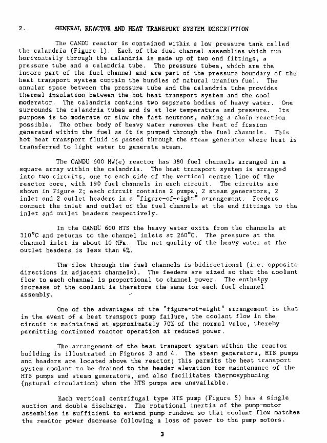
The CANDU reactor is contained within a low pressure tank calledthe calandria (Figure 1). Each of the fuel channel assemblies which runhorizontally through the calandria is made up of two end fittings, apressure tube and a calandria tube. The pressure tubes, which are theincore part of the fuel channel and are part of the pressure boundary of theheat transport system contain the bundles of natural uranium fuel. Theannular space between the pressure tube and the calandria tube providesthermal insulation between the hot heat transport system and the coolmoderator. The calandria contains two separate bodies of heavy water. Onesurrounds the calandria tubes and is at low temperature and pressure. Itspurpose is to moderate or slow the fast neutrons, making a chain reactionpossible. The other body of heavy water removes the heat of fissiongenerated within the fuel as it is pumped through the fuel channels. Thishot heat transport fluid is passed through the steam generator where heat istransferred to light water to generate steam.
The CANDU 600 MW(e) reactor has 380 fuel channels arranged in asquare array within the calandria. The heat transport system is arrangedinto two circuits, one to each side of the vertical centre line of thereactor core, with 190 fuel channels in each circuit. The circuits areshown in Figure 2; each circuit contains 2 pumps, 2 steam generators, 2inlet and 2 outlet headers in a "figure-of-eight" arrangement. Feedersconnect the inlet and outlet of the fuel channels at the end fittings to theinlet and outlet headers respectively.
In the CANDU 600 HTS the heavy water exits from the channels at310°C and returns to the channel inlets at 260°C. The pressure at thechannel inlet is about 10 MPa. The net quality of the heavy water at theoutlet headers is less than 4%.
The flow through the fuel channels is bidirectional (i.e. oppositedirections in adjacent channels). The feeders are sized so that the coolantflow to each channel is proportional to channel power. The enthalpyincrease of the coolant is therefore the same for each fuel channelassembly.
One of the advantages of the "figure-of-eight" arrangement is thatin the event of a heat transport pump failure, the coolant flow in thecircuit is maintained at approximately 70% of the normal value, therebypermitting continued reactor operation at reduced power.
The arrangement of the heat transport system within the reactorbuilding is illustrated in Figures 3 and 4. The steam generators, HTS pumpsand headers are located above the reactor; this permits the heat transportsystem coolant to be drained to the header elevation for maintenance of theHTS pumps and steam generators, and also facilitates thermosyphoning(natural circulation) when the HTS pumps are unavailable.
Each vertical centrifugal type HTS pump (Figure 5) has a singlesuction and double discharge. The rotational inertia of the pump-motorassemblies is sufficient to extend pump rundown so that coolant flow matchesthe reactor power decrease following a loss of power to the pump motors.

STEAM PIPES
PRESSURIZER
ll J '''•'''''•'I'V'A''•jl^_^i':''i''iiiV ''
LIGHT WATER STEAM
LIGHT WATER CONDENSATE
HEAVY WATER COOLANT
HEAVY WATER MODERATOR
MODERATOR HEAT EXCHANGER '
FIGURE 1 CANDU NUCLEAR STEAM SUPPLY SYSTEM
4

STEAM GENERATOR
PUMP
OUTLET HEADER
OUTLETHEADER
STEAMGENERATOR
INLET HEADER
PUMP
INLETHEADER
STEAM GENERATOR
PUMP
INLET HEADER
LOOP
LOOP
INLETHEADER
OUTLET HEADER
n
OUTLETHEADER
PUMP
STEAMGENERATOR
FIGURE 2 A HEAT TRANSPORT SYSTEM

1 MODERATOR HEAT EXCHANGER2 MODERATOR PUMP3 REACTOR
FIGURE 3 LOCATION OF MAIN MODERATOR SYSTEM EQUIPMENT

g REACTOR
PLAN VIEW PUMP MOTORS OMITTED FOR CLARITY
FIGURE 4 CANDU 600 HEAT TRANSPORT SYSTEM — MAIN CIRCUIT ARRANGEMENT(PLAN AND ELEVATION)

1 UPPER OIL POT COVER2 UPPER BEARING OIL POT3 THRUST BEARING RUNNER4 DOWN THRUST BEARING5 UP THRUST BEARING6 UPPER BEARING COOLING COILS7 BRAKE DRUM8 MOTOR SHAFT9 OIL LEVEL CONTROL
10 BEARING COOLING WATER PIPES11 AIR COOLER WATER PIPES12 MAIN TERMINAL BOX13 AIR DUCT14 AIR DUCT15 FAN RING16 STATOR CORE ASSEM3LY
17 ROTOR ASSEMBLY18 THRUST DISC19 SPACER COUPLING20 MOTOR STAND21 MOTOR STAND ACCESS DOORS22 PUMP SHAFT23 VAPOUR CONTAINMENT SEAL24 TERTIARY MECHANICAL SEAL25 SECONDARY MECHANICAL SEAL26 PRIMARY MECHANICAL SEAL27 PUMP BEARING28 PUMP CASE29 CASE WEAR RING30 PUMP DISCHARGE ELBOWS31 PUMP SUCTION SPOOL PIECE32 LOWER GUIDE BEARING ASSEMBLY
FIGURE 5 TYPICAL CANDU 600 HEAT TRANSPORT PUMP8
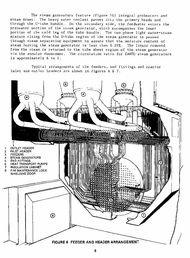
The steam generators feature (Figure 10) integral preheaters andsteam drums. The heavy water coolant passes into the primary heads andthrough the U-tube bundle. On the secondary side, the feedwater enters thepreheater section of the steam generator, which encompasses the lowerportion of the cold leg of the tube bundle. The two phase light water-steammixture rising from the U-tube region of the steam generator is passedthrough steam separation equipment to assure that the moisture content ofsteam leaving the steam generator is less than 0.25%. The liquid removedfrom the steam is returned to the tube sheet region of the steam generatorvia the annular downcomer. The circulation ratio for CANDU steam generatorsis approximately 6 to 1.
Typical arrangements of the feeders, end fittings and reactorinlet and outlet headers are shown in Figures 6 & 7.
OUTLET HEADERINLET HEADERFEEDERSSTEAM GENERATORSEND FITTINGSHEAT TRANSPORT PUMPSINSULATION CABINET
8 F/M MAINTENANCE LOCKSHIELDING DOOR
FIGURE 6 FEEDER AND HEADER ARRANGEMENT
9
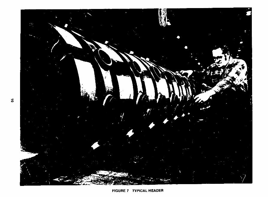
FIGURE 7 TYPICAL HEADER

3. OUT-REACTOR HEAT TRANSPORT SYSTEM DESIGN AND MATERIALCONSIDERATIONS
The CANDU Heat Transport System (HTS) has features similar toother water cooled reactors, but one of the unique features is the use ofcarbon steel as the out-of-reactor pressure boundary material (with theexception of the steam generator tubes). With the carbon steel HTS circuit,the capability and manufacturing facilities within Canada were able to bemora utilized for supply of the components. This section deals with thedesign and material considerations, particularly with regard to selection ofcarbon steel.
Carbon steel has a long and successful history as a power plantmaterial in fossil-fired stations. Fabricators and construction sitepersonnel are used to handling this material. The decision to use carbon
steel in both the CANDU-PHWR heat transport system and in thesecondary systems was made in the late 1950's for the NPD reactor atRolphton, Ontario. This policy has been maintained in all CANDU nuclearsteam plants with consistent success.
A number of advantages have been identified with the choice ofcarbon steel. These are:
(a) Cost
Carbon steel piping is less expensive than the alternative, stainlesssteel, by a factor of three for both the capital cost and the installedcost.
(b) Availability/Familiarity
Carbon steel has well known mechanical properties and is available in awide range of product forms from many suppliers.
(c.) Assembly
The procedures for welding carbon steel are well developed and allowgreater latitude in parameters than procedures for low alloy steels andstainless steels. The majority of the piping is of a size that doesnot require post weld heat treatment. Thus construction is simplifiedand construction time is shorter than that for higher alloyed steels.Most of the piping is to SA106B requirements and supplied in thenormalized condition. Bending of feeders is used to minimize welds andeliminate fittings.
(d) Compatibility with the Environment
The resistance of carbon steel to general corrosion, localizedcorrosion, erosion corrosion, impurity attack and activity transport isvery suitable for the 300°C heavy water environment in the HTS. Majorfactors relating to the environment compatibility of carbon steel arereviewed bellow:
11

General Corrosion
The separation of the heat transport heavy water from themoderator heavy water enables the water chemistry in both systems to beoptimized. As no reactivity control is done in the CANDU-PHWR heattransport system, its water chemistry is optimized to minimize corrosion,corrosion product transport and the activation of the mobile corrosionproducts. Chemical additions for reactivity control are made to the lowtemperature moderator system. The actual long-term corrosion rates ofcarbon steel, as determined from corrosion coupons exposed to heat transportsystem heavy water at operating CANDU PWHR plants, average less than two (2)micrometers per year. Thus the total corrosion over the life of the plantwill be less than 0.1 mm. This is less than 15% of the design basiscorrosion allowance for large diameter components.
The resistance of carbon steel to corrosion is based upon themaintenance of a film of magnetite (Fe30|,) on the carbon steel. Thismagnetite film is developed by a conditioning treatment prior to reactoroperation. It is maintained by controlling the pH within the rang" 10-10.5and keeping low dissolved oxygen concentrations, typically less than 15micro g Oa/kg D20. Under such conditions the corrosion rate of carbon steelcontinuously decreases to extremely low rates. The low oxygen conditionsare easily maintained.
Atmospheric corrosion is neglible in the warm dry atmosphere ofthe reactor vault since the atmosphere is dried to recover heavy watermoisture.
Localized Corrosion and Impurity Attack
The factors affecting localized corrosion of carbon steel, notablycaustic concentrations do not occur in the CANDU HTS piping system.Impurities such as low concentrations of chlorides do not cause stresscorrosion cracking as they can with stainless steel. The heat transportsystem is maintained at a high purity by ion exchange equipment and impuritylevels do not become a problem. Oxygen concentrations are maintained atvery low values in the non-boiling CANDU plants and although measurable arestill low in the boiling systems.
Compared to stainless steel with its susceptibility to stresscorrosion cracking or sensitization cracking in oxygenated environments,carbon steel is an optimum choice.
Erosion Corrosion
Feeders are sized to ensure heavy water velocities are belowdesign limits that have been established by testing and experience tominimize erosion or erosion corrosion effects. Generally, 17 m/s is used asa design limit.
12

A joint AECL/Ontario Hydro (Reference 1) test program was carriedout between 1980 December and 1982 April, i.e. for a period 482 days, toassess the erosion-corrosion of carbon steel piping at a temperature of300°C and at velocities of 9.5 m/s, 23 m/s and 38.1 m/s. The waterchemistry was generally maintained at pH values (measured at 25°C) between10 and 11 and with dissolved oxygen concentrations below 15 micro g Og/kgH20. The test pieces included 90° elbows and straight pipe.
The uniform metal loss rate found in the test program confirmedthe very low rates found from corrosion coupon measurements at Pickering NGS'A1 which indicate rates of 2 to 3 micrometers per year, or 60 to 90micrometers over 30 years. These values are only 3 percent of the corrosionallowance of 2700 micrometers.
At the 38 m/s flow rate, which is more than twice the actualmaximum flow rate, pitting to a depth of 50 micrometers was observed. Nopitting was observed at the lower velocities of 23 m/s and 9.5 m/s.
This work confirmed the design limit used. In addition wallthickness measurements at operating plants have not detected any wallthickness loss on bends or straight sections of feeders.
Activity Transport
During reactor operation, small amounts of corrosion products(called crud) are released from the walls of the piping and are transportedthroughout the HTS circuit. Deposition of this crud on the fuel for aperiod of days or weeks would cause it to become radioactive and uponrelease from the fuel the now irradiated crud could deposit on the out-reac-tor circuits where it would contribute gamma radiation to the operatingenvironment. The pH range specified for the CANDU-PHWR HTS coolant has beenchosen not only to achieve low crud release rates from the carbon steel butalso to discourage the deposition of the crud on the fuel. As a result theactivation of the crud is minimized. The degree of activation of the crudis further reduced by controlling the impurity levels in the materials usedfor the HTS components, particularly cobalt content, because of theactivation of CoB9 to CoGG which could occur as crud resides within orpasses through the reactor core.
13

4. FABRICATION CONSIDERATIONS OF THE MAJOR HTS COMPONENTS
General
In this section, various fabrication aspects of the major out-reactor components used in the heat transport system are covered withparticular emphasis on the pressure boundary aspects. The componentsincluded are the steam generators, the HTS pumps, HTS auxiliary systemvalves, the feeders and headers and main HTS piping.
However, prior to discussing individual components, a few commentsare appropriate regarding material toughness. Designers and users are wellaware of the need for good fracture toughness in the nuclear pressureboundary materials. This is needed in order to ensure brittle fracture doesnot occur and to provide resistance to the growth of any defects that mayhave been undetected.
AECL therefore specifies that pressure boundary components of theheat transport system, are capable of meeting an RTNtyj> (Nil-DuctilityReference Temperature) of -6.7°C (+20°F) or lower. The reasons are:
(i) This allows the system hydrostatic test at site to be done at26.7°C (80°F) which fully meets the ASME Code recommendation of atest temperature of 60°F above the RT̂ jyp temperature. A higherRT̂ prp would require heating of the system during hydrostatictesting.
(ii) With a low Nil-Ductility Reference Temperature, the heat transportsystem when shutdown during service, can be pressurized in theambient condition. This increases flexibility of operation of theCANDU system, allowing relatively short heatup times.
(iii) Also, indirectly the specification of a low RT̂ jyp results in abetter quality of steel, since it is only achieved by good controlof chemical composition, melting practice, material formingprocesses and heat treatment.
Our experience is that the RT̂ jyp temperature of -6.7°C (+20°F) or lower, canbe obtained on all the carbon steel components, even on tubesheets of thesize required for CANDU steam generators.
A further consideration that generally applies to all HTScomponents is cobalt concentration. Cobalt has been identified as a majorcontributor to radiation fields in many reactor systems. Trace quantitiesare present in all steels. Thus any cobalt containing corrosion particulatethat is circulated through the reactor becomes radioactive from its cobaltcontent. AECL has found it practical to specify and obtain low cobaltcontent (typically less than O.U1%) at a small cost premium, on all HTSpressure boundary components.
14

Steam Generator
CANDU steam generators (Figure 10) both on the secondary side aswell as the primary side, are designed and fabricated to the rules of ASMESection III Class 1 with additional AECL requirements imposed in someareas. Typical materials are given in Table 2. The exceptions to thecarbon steel grades are the tubes and the tubesheet overlay.
TABLE 2
TYPICAL CANDU STEAM GENERATOR MATERIALS
Shell
Heads
Tubesheet
T/S Overlay
Nozzles
Internal Shrouds
Tubing
SA516-70
SA516-70
SA508 Cl-2
Ni-Cr-Fe
SA541 Cl-2
A515 or A516
Ni-Fe-Cr
Because of the ability to control the chemistry of the primarycircuit to a high pH and low oxygen, use of carbon steel provides aneconomic benefit in material cost and weldability. The relatively smalldiameters and lower design pressures of CANDU steam generators does notnecessitate high strength low alloy steel plate to achieve reasonableshipping weights. Hence, low cost, readily weldable SA-516 Gr70 plate isused for the shell as opposed to say SA-533 plate. For instance, the steamdrums in CANDU-600 steam generators are typically 4 m diameter and 73 mmwall thickness.
Tubesheets are forgings with emphasis placed on steel making andforging practice to achieve high steel cleanliness. A Ni-Cr-Fe weld metalof composition compatible with the tube material and of high integrity isdeposited on the primary side of the tubesheet by techniques that keepdistortion to a minimum. The welding process itself is the prerogative ofthe manufacturer and both MIG and submerged arc processes have been usedsatisfactorily. Tubesheets are typically 2.5 m diameter and 380 mm thick.
15

The secondary side shell and the primary and secondary heads areformed from plate. The plate material must meet both the requirements ofthe ASME pressure vessel code and the additional requirements of the AECLspecification. Supplier's fabrication processes are reviewed to assure thematerial can meet the required properties. Emphasis is placed onappropriate through - thickness properties to prevent problems such aslamellar tearing. All the heads for a CANDU 600 steam generator are made asone piece. Two piece heads are not excluded but they are not necessary forthe size of head used in the CANDU 600 plants.
For the shell and nozzle welds, submerged arc and manual shieldedarc welding techniques are generally used. For welds finished from one sidewith restricted access to the opposite side, TIG root pass techniques areused. AECL specifies requirements for preheat before thermal cutting,preheat for all pressure boundary welding and additional NDE of weldpreparation sufaces prior to welding. Surface NDE requirements are alsospecified for first and final passes of welds in addition to the ASMESection III requirements.
HTS Pumps
Typical CANDU HTS pump is shown in Figure 5. As with otherprimary side components, the pump pressure boundary is designed, built andtested to the requirements of the ASME Boiler and Pressure Vessel Code,Section III, Class 1. The pressure boundary includesthe pump casing and the pump cover which is mounted on the top of the casingand sealed by a double gasket. The casing consists of a vertical bottomsuction nozzle, the main bowl and two horizontal discharge nozzles.
In CANDU reactors, the pressure tube and fuel design characteris-tics lead to higher head, lower flow heat transport pumps compared withthose of the PWR. Hence the pump characteristics (e.g. specific speednumber) allow the use of a volute type casing rather than one with internaldiffusers around the impeller.
The CANDU pump bowls are a relatively simple one-piece carbonsteel casting. The pump casing is SA-216 Grade WCC, and weighsapproximately 7000 kg. with a 50 cm pump suction nozzle and two 40 cmdischarge nozzles.
The cover is a welded fabrication of two forgings. The horizontalcover flange and vertical cylinder (stuffing box) are of ASME SA-350Grade LF2, ultrasonically inspected carbon steel. The stuffing box alsocontains the pump shaft seals. The cover assembly weighs approximately2200 kg.
Pump shafts are of forged steel, containing not less than 11%chromium. SA-479 type 410 is the typical specification used. Shafts aretypically 200 mm diameter and 1.8 m long.
The impellers are typically martensitic stainless steel casting toSA-487 Class CA6NM. Impellers are single stage, 0.86 m in diameter andweighing 365 kg.
16

Valves
The use of valves has been avoided entirely in the main circuitsof the Heat Transport System. In the heat transport auxiliary systems, suchas Pressure and Inventory Control and Shutdown Cooling, gate and globevalves are used for isolation and flow routing purposes and control valvesfor feed and bleed control. The valves used are extremely reliable andincorporate design features specifically to minimize leakage to atmosphere(bellows seals on low-stroke valves, live-loaded packing on long-strokevalves).
As with the main heat transport system, the principal material ofconstruction for the heat transport auxiliary systems is carbon steel.Hence, valve bodies are typically castings to ASME SA-216 Grade WCB orequivalent carbon steel forged material. Low cobalt content is specified asdescribed previously and our experience is that it can be obtained at asmall premium. Because of its high cobalt content, Stellite is not acceptedas a hard facing material. Where hard facing is needed, cobalt-free alloysare currently specified. Cobalt-free hard facing alloys have been used inCANDU systems since the early 1970's.
The valve gland is an important area of material selection. Forvalve stems, the materials specified are required to have qualities ofdimensional stability, wear resistance, and low friction for satisfactoryoperation. For control valves, oxidized Zircaloy, 17-4 pH SS, and Inconel625 are typically used. When martensitic stainless steel (e.g. ASME SA-276and SA-479 Tp 410) is used, controls on hardness and low levels of dissolvedoxygen in the system lessen the susceptibility to the intergranular stresscracking experienced in some LWR-s.
Where a bellows seal is specified, Inconel 600 is typically chosenas the bellows material because of its resistance to fatigue. In a packedgland, the packing materials are specified and the packing is live-loaded bymeans of disc springs to a specific stress. This results in virtually zeroleakage.
Feeders, Headers and HTS Piping
The feeder/header and end fitting arrangements for CANDU 600 areshown in Figure 6. An inlet and an outlet feeder connect each fuel channelto the large diameter HTS piping system. Each feeder consists of a singlesmall diameter (38 mm to 88 mm dia.) pipe run starting with a mechanicalconnection at the fuel channel and ending at the welded connection at theheader nozzle. In between the ends, each feeder consists of variousstraight runs and bends that vary from approximately 30° to 90 . There areno T-junctions or valves in the feeders. The 380 feeders at each end of thereactor run from the fuel channels vertically up the face of the reactor andthen horizontally across and above the fuelling machine area to the reactorheaders. Due to the fuel channel arrangement, the feeders are grouped inarrays of small diameter pipes following essentially parallel paths from thereactor face to the headers. Feeder lengths vary from 6 to 20 meters. Thefeeders are enclosed in an insulated feeder cabinet and experience hot dryatmosphere during reactor operation.
17

Feeders are designed and fabricated to the requirements for Class1 components of the ASME Boiler and Pressure Vessel Code Section III. Theyare fabricated from seamless carbon steel, SA-106 Gr B pipe with additionalmechanical property and cleanliness requirements to ensure good forming,welding and service performance. The feeder pipe is typically produced fromfully killed Electric Furnace steel, cold drawn to achieve tight dimensionaltolerances and normalized. Feeders are fabricated typically by bending andswaging operations using double random length pipes (9 - 11 m long) in orderto minimize the number of welds. Particular attention is given to thefeeder pipe surface finish, low Cobalt content (Co < 0.006%) and very lowinclusion content in the steel to provide a highly reliable piping system.Also, special measures are taken to ensure corrosion protection of thefeeder pipe material during transportation, fabrication, storage and siteinstallation.
The reactor inlet and outlet headers (shown in Figure 7) areessentially manifolds. The CANDU 600 has four inlet headers (approximately6.4 m long x 0.37 m I.D. x 57 mm thick) and four outlet headers (approxi-mately 6.5 m long x 0.41 m I.D. x 64 ram thick). The requirements for goodmechanical properties and tight dimensional tolerances of the header and theuse of extruded feeder nozzle connections required the development ofspecialized material and manufacturing technology. As a result of closecooperation between AECL and industry, this has been fully accomplished.
The Reactor Header body material is typically produced either byvacuum arc remelt or electro slag remelt process to meet required mechanicaland AECL specified chemical and cleanliness requirements. The feeder andmain HTS piping nozzle connections to the reactor headers are typicallymanufactured by an extrusion process applied to the base seamless carbonsteel material of the header e.g. SA-106 Grade B. This process provides anoptimum nozzle configuration for the feeder-to-header connections both fromthe structural reliability viewpoint and for the hydraulics of the circuit.Thus the need for a large number of set-on or set-thru nozzle forgings withthe associated welding is eliminated via use of the extruded nozzles.
Manufacturing of Reactor Headers is monitored by AECL from earlystages of steel making to the final heat treatment and machining to ensure ahigh reliability product. The finished headers are then sent to thefeeder/header fabricator, who attaches the upper section of each feeder toform the feeder modules that are subsequently shipped to site. Thefeeder/header frame assemblies involve relatively conventional pipe bendingand welding technology similar to that used in many conventional fossil-boiler shops.
The main HTS system piping of the CANDU 600 uses SA106 Gr. Bseamless carbon steel pipe and SA-105 and SA-181 Gr. II forged fittings withadditional chemical, mechanical and NDE requirements. The major portion ofthe HTS contains 40, 46 and 50 cm dia, schedule 100 piping. In addition tothe ASME Section III Code requirements, AECL requires the piping to meetadditional requirements on: Cobalt content, tight cleanliness requirements,tighter dimensional tolerances, higher frequency of mechanical testing (bothends of each length of pipe) and tighter NDE requirements. Although theASME code allows use of the seam welded piping, the AECL approach has beento use seamless piping exclusively to enhance overall system reliability.
18

5. OPERATIONAL EXPERIENCE
The CANDU PHWR's have achieved an enviable performance record notonly in high capacity factors and reliability (Tables 3 and 4) but also inlow man-rem exposures of the operating personnel (Figure 8) and a lowenvironmental impact from the radioactive materials which are released tothe environment (Figure 9 and Table 5) . Many factors have contributed tothis good performance, including the reliable performance of the CANDUprimary heat transport system and process components.
One of the most meaningful ways of quantifying componentexperience is in terms of the incapability caused by them as a percentage ofattainable production in the time period under consideration. If agenerating unit is able to operate at full power all of the time, theCapability Factor would be 100% (and the Incapability Factor would be 0%).In practice, the Capability Factor is less than 100% because of outages(full shutdowns) and deratings (operating at less than full power). Hence,the Incapability Factor indicates the inability of a unit to operate at fullpower all of the time.
TABLE 3
CAPACITY FACTORS OF CANDl
Name
Pickering - 8Pt. LepreauBruce - 5Bruce - 7Bruce - 3Bruce - 4Bruce - 1Bruce - 6Pickering - 5Pickering - 7Pickering - 4Wolung - 1Pickering - 3Pickering - 6Bruce - 2Pickering - 2(x)Pickering - l(')Gentilly-2(2)Embalse (2)
(1) Shutdown for pressure
(2) Capacity Factors arerestrictions.
In ServiceDate
86 Feb 2883 Feb 185 Mar 186 Apr 1078 Feb 179 Jan 1877 Sep 184 Sep 1483 May 1085 Jan 173 Jun 1783 Dec 2872 Jun 184 Feb 177 Sep 171 Jul 2971 Dec 3083 Oct 184 Jan 20
tube replacement.
J PHWR's
Life TimeCF(%)
96929290888785848383828077777765646359
lower than Availability Factors
1986CF(%)
969497908493657990758380697557
006859
due to grid
19

The equipment which has caused incapability at the Pickering A andB, Bruce A and B Nuclear Generating stations over the lifetime of thoseplants is shown in Table 6 (taken from Reference 2). As can be seen fromthe table there are three groups of equipment e.g. Group A - thoseassociated with the reactor (fuel, pressure tubes, on power refuelling),Group B - process components associated with the heat transport system andother process systems (steam generators, heat transport pumps, heatexchangers, valves, feeders, headers and HTS piping) and Group C - turbineand generator, instrumentation and control, and others.
WATER
TABLE 4
WESTERN WORLD RANKING OFCOOLED REACTORS OF MORE THAN 400 MW(e)
Year 1985(l)
Plant
Hamaoka-1
Shimane
PT. LEPREAU
BRUCE-1
Grohnde
WOLSUNG
Salem-1
Loviisa-1
PICKERING-7
Oconee-1
Unterwesser
Loviisa-2
Grafenrheinfeld
Nine Mile Point
Ginna
(a) Since generating(1) Nucleonics Week(2) Nucleonics Week
CapacityFactor (%)
99.01
98.51
97.38
96.16
95.98
94.35
93.93
93.00
92.96
92.85
91.97
91.70
90.80
90.77
90,37
first electricity :1986 Jan. 30 Vol 271987 Feb. 5 Vol 28
Year 1986(
Plant
Ikata-2
Mihama-3
Genkai-2
St. Lucie-1
Ohi-2
BRUCE-5
Calvert Cliffs-2
Olkiluoto
PICKERING-8(a)
PT. LEPREAU
BRUCE-7
Kori-6(a)
BRUCE-4
Takahama-3
Forsmark-1
Ln 1986.No. 5.No. 6.
2)CapacityFactor (%)
99.96
99.95
99.44
99.42
99.38
97.31
94.91
94.17
94.04
93.96
93.68
93.37
93.14
93.05
92.46
20

-1900
fQLJJ
C/>
iin
55.111(AOD
i
in
i3
PWR and BWR data from Nuclear Eng. Int'l. 1986 April p49
CANDU data from relevant Station Annual Reports.
77 78 79 80 81 82 83 84 85
CALENDAR YEAR
100
76
FIGURE 8 COMPARATIVE OCCUPATIONAL DOSES FOR CANDU PHWRs, PWRs and BWRs
21

CC
55
o5
UJ10OQUJCO
Q.
Q
o
50
40
30
CANADIAN TARGET (OPERATIONAL LIMIT)
ACTUAL CANDU 600 PERFORMANCE
• GENTILLY 2 (QUEBEC CANADA)
• POINT LEPREAU (NEW BRUNSWICK CANADA)
D EMBALSE (ARGENTINA)
O WOLSUNG (KOREA)
15 20 25 30
YEARS OF REACTOR OPERATION
FIGURE 9 RADIATION DOSE TO THE CRITICAL PUBLIC GROUP DUE TO RADIOACTIVE EMISSIONSFROM CANDU 600 POWER PLANTS, ESTIMATED AND ACTUAL
22

ITABLE 5
ENVIRONMENTAL IMPACT OF RADIOACTIVE RELEASES
ANTICIPATED AND ACTUAL 1985 WHOLE BODY PUBLIC DOSEAT CANDU 600 STATION BOUNDARY
Predicted Dose Rates Actual 198b Dose Ratesto a Member of the to a Member of thePublic Critical Group Public Critical Group*Microsieverts/Year Microsieverts/Year
GASEOUS EMISSIONS
Noble Gases 2.0 3.0
Tritium 1.5 0.9
Particulates 0.2 0.4
Radioiodines 0.2 0.4
Carbon-14 0.2 0.2
Total Airborne 4.1 4.9
LIQUID EMISSIONS
Tritium
Total Beta-Gamma
Total Waterborne
Total Dose to Memberof Public CriticalGroup
* Based on the Average CANDUsite.
5.0
2.0
7.0
11.0
600 release
0.
1.
1.
6.
being released at
3
0
3
4
the Gentilly-2
23

TABLE 6
EQUIPlffiNT CONTRIBUTION OF LIFETIME^)INCAPABILITY TO DECEMBER 31, 1985
Cause ofIncapability
Group A
On^Power FuellingFuelPressure Tubes
Group B
Steam GeneratorsHeat Transport PumpsHeat ExchangersValvesFeeders, Headers and
HTS Piping
Group C
Turbine and GeneratorInstrumentation and ControlOther
Total Equipment Incapability
Labour Dispute(2)
Station Incapability Factor
Station Capability Factor
Number of Units
Unit Years Since In-Service
PickeringNGS-A
0.60.112.4
0.40.21.00.4
0.0
6.5O.S1.5
23.6
2.1
25.7
74.3
4
54.5
(1) Lifetime means since in-service date(2) 1985 Labour dispute plus 1972 Labour
Incapability (%)PickeringNGS-B
0.20.00.0
0.10.13.30.4
0.0
6.61.11.9
13.7
3.4
17.1
82.9
3
5.6
BruceNGS-A
0.60.01.1
1,5O.S0.10.2
0.0
4.41.43.1
13.0
0.7
13.7
86.3
4
31.5
of each unit,dispute for Pickering
BruceNGS-B
0.00.00.0
0.00.00.00.6
0.0
0.72.05.4
8.7
4.5
13.2
86.8
2
2.1
NGS-A.
24

It is observed that Group B (which covers the out-of-reactorprocess components associated with the heat transport system and otherprocess systems) has made a relatively small contribution to the overallstation incapability factor. For instance, steam generators, HTS pumps andvalves together have only caused 1.8% incapability at Pickering A and 2.3%incapability at Bruce A. Feeders, headers and HTS piping equipment have notcaused any incapability at any CANDU nuclear plant. This effectivelyillustrates the high reliability of CANDU process components.
Process components in the CANDU-PHWR are not only required toprovide high reliability and high maintainability but they must also providevery low heavy water leakage. This particularly applies to pump and valveseals.
The heat transport pumps operate continuously at high temperatureand pressure. This rigorous environment combined with the large shaft sizesmakes these seals the most critical of all CANDU pump seals. Within Canada,an extensive, in-depth technology of high reliability HTS pump seals (thathave virtually zero leakage) has been developed by AECL and Canadianindustry. Both long seal life (3 to 5 years) and short replacement timeshave been achieved. Also, as an example of maintainability, motors do nothave to be removed, nor do large pumps have to be dismantled to change shaftseals.
In the CANDU-PHWR, the valve requirements are similar to those forother reactor types, that io they must open, close or regulate flow withhigh reliability and with acceptably low leakage to the atmosphere.However, the need to minimize heavy water leakage has led to significantimprovements in the design, manufacture and application of the valves usedfor heavy water service.
In order to minimize heavy water upkeep costs and incapability,the following approaches are applied:
1. The number of heavy water valves is minimized.
2. The number of ordinary water valves in heavy water recovery areas isminimized.
3. Valves have special design features to minimize leakage, such as:
(a) Minimum mechanical joints (welded connections and seal weldedbonnets).
(b) Zero leakage valves (bellows valves, diaphragm valves).
(c) Special developed live-loading of valve stem packings viasprings.
(d) Double packing with leakage collection at the midpoint.
25

It should be noted that, where isolation is occasionally required and valvesare not provided, temporary ice plugs are used. For example, to isolate anddrain a pressure tube for inspection or maintenance, ice plugs are formed inthe inlet and outlet feeder pipes using jackets filled with liquid nitrogen.These jackets are permanent installations.
The successful application of the approaches to preventing theescape of heavy water from CANDU pumps and valves is demonstrated by thegood heavy water upkeep experience. Heavy water upkeep is the cost ofreplacing any heavy water losses and upgrading any downgraded water torestore its isotopic purity to about 99.8 weight per cent.
Typically, at Pickering A & B and at Bruce A & B, the Heavy WaterUpkeep Unit Energy Costs are only 2 to 4 percent of Total Unit Energy Costs•The 1985 performance is shown in Table 7 (taken from Reference 1).
1985
Total Unit Energy Cost(S/MWhe)
Heavy Water Upkeep UnitEnergy Cost($/MWhe)
% of TUEC
(l)Heavy water upkeep costsPickering NGS-A Units 1replacement.
TABLE
HEAVY WATER
PickeringNGS-A(l
23.3
0.9
3.9
7
UPKEEP COSTS
Pickering) NGS-B
44.6
0.7
1.6
BruceNGS-A
23.2
0.3
1.3
are based on Units 3 and 4 only,and 2 were shutdown for large scale
BruceNGS-B
43.5
0.3
0.7
fuel channel
26

STEAM OUTLET NOZZLESECONDARY STEAM CYCLONESPRIMARY STEAM CYCLONESCHEMICAL FEED NOZZLE AND HEADERDOWNCOMER ANNULUSREHEATER DRAINS RETURN ANDEMERGENCY WATER SUPPLY NOZZLEU-BEND SUPPORTSTUBE BUNDLETUBE SUPPORT PLATEBACK-UP SUPPORTSOBSERVATION PORTBLOWDOWN NOZZLEDIVIDER PLATE
14151617181920
2122
D2O INLET NOZZLEBASE SUPPORTD2O OUTLET NOZZLEBAFFLE PLATEPREHEATERLATERAL SUPPORTSWATER LEVELCONTROL TAPSMANWAYFEEDWATER NOZZLE
FIGURE 10 600 MW STEAM GENERATOR
27

6. CONCLUSIONS AND SUMMARY
The paper has dealt with a wide range of material and fabricationaspects of the out-reactor process components of the CANDU-PHWR heattransport system. In summary, some of the key considerations andconclusions are:
(a) The CANDU PHWR provides separation of the HTS from the low temperaturemoderator circuit. Hence, as no reactivity control is done in the HTS,the design and chemistry is optimized for the carbon steel pressureboundary material.
(b) In the HTS, carbon steel is the principal material used for thepressure boundary of the out-of-reactor process components (with theexception of the steam generator tubes).
(c) Specific design and operational measures are taken to controlcorrosion, erosion, corrosion product transport and the activation ofthe mobile corrosion products. Additional measures to achieve goodfracture toughness result in advantages in flexibility of systemoperation at low temperatures, should this be needed.
(d) From a fabrication point-of-view, carbon steel has advantages ofeconomics, well-known mechanical properties, ease of fabrication andwelding, and wide availability in the required product forms.
(e) CANDU PHWR's with carbon steel HTS have achieved an enviableperformance record. This has been not only high capacity factors andcomponent reliability but also low heavy water upkeep costs, lowrelease of radioactive materials to the environment, and low raan-remexposures to the operating personnel.
REFERENCES
1. "Final Analysis of the Single Phase Erosion/Corrosion Test Programmefor Reactor Inlet Headers" J.M. Kenchington, B.M. Pearson, E.V. Murphy,Canadian Nuclear Association Annual Conference, Montreal 1983.
2. Ontario Hydro CANDU Operating Experience, R.W. Batholomew,L.W. Woodhead, S.G. Horton, G.R. Fanjoy, Ontario Hydro NGD-9 (1985).
28

The International Standard Seiial Number
ISSN 0067-0367
has been assigned to this series of reports.
To identify individual documents in the serieswe have assigned an AECL-number.
Please refer to the AECI^number whenrequesting additional copies of this document
from
Scientific Document Distribution OfficeAtomic Energy of Canada Limited
Chalk River, Ontario, CanadaK0JU0
I A' numcro dc serie standard international
ISSN 0067-0367
a cte attribue a cette serie de rapports.
Pour identifier les rapports individuels faisant partiede ccttc serie nous leur avons attribue un nuniero AECL-
Veuillez faire mention du numero AECL- si vousdemandez d'autres excmplaires de ce rapport
au
Service de Distribution des Documents OfficielsL'Energie Atomique du Canada, Limitee
Chalk River, Ontario, CanadaK0J 1J0
Price $3.00 per copy Prix SJ.OO par exemplaire


![[ CANDU Poster]a Modified Dedicated Observer Approach to Fault Detection in CANDU Rx](https://img.dokumen.tips/doc/110x75/577cd4391a28ab9e7897f7c3/-candu-postera-modified-dedicated-observer-approach-to-fault-detection-in.jpg)