Embed Size (px)
Citation preview
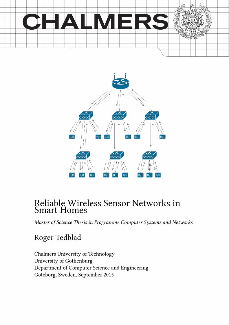
Reliable Wireless Sensor Networks in
Smart Homes
Master of Science Thesis in Programme Computer Systems and Networks
Roger Tedblad
Chalmers University of Technology
University of Gothenburg
Department of Computer Science and Engineering
Göteborg, Sweden, September 2015
The Author grants to Chalmers University of Technology and University of Gothen-
burg the non-exclusive right to publish the Work electronically and in a non-commercial
purpose make it accessible on the Internet.
The Author warrants that he/she is the author to the Work, and warrants that the Work
does not contain text, pictures or other material that violates copyright law.
The Author shall, when transferring the rights of the Work to a third party (for example
a publisher or a company), acknowledge the third party about this agreement. If the
Author has signed a copyright agreement with a third party regarding the Work, the
Author warrants hereby that he/she has obtained any necessary permission from this
third party to let Chalmers University of Technology and University of Gothenburg
store the Work electronically and make it accessible on the Internet.
Reliable Wireless Sensor Networks in Smart Homes
Roger Tedblad
©Roger Tedblad, September 2015.
Examiner: Marina Papatrianta�lou
Supervisor: Giorgos Georgiadis
Chalmers University of Technology
University of Gothenburg
Department of Computer Science and Engineering
SE-412 96 Göteborg
Sweden
Telephone + 46 (0)31-772 1000
[Cover: Figure 5.1; the proposed round-robin algorithm as described in Chapter 5 ]
Department of Computer Science and Engineering
Göteborg, Sweden September 2015
Abstract
Wireless sensor communications play a key role in the emerging Internet of Things
digital ecosystem. As the industry now gets ready to roll out the second generation of
IoT-devices, e�ort is directed to fully standardize the protocol suite of wireless sensor
networks, and assure full IP connectivity with devices. The protocols CoAP and MQTT
are possible candidates for a highly functional application layer for the Internet of
Things in terms of reliable transmissions and adherence to the less verbose attributes of
wireless sensor networks where sleep cycles are utilized in an e�ort to keep the overall
power utilization of end nodes low. Given these attributes, the protocols limit the
number of messages sent to the minimum necessity in order to convey a current sensor
value or actuating data. In neglecting other forms of communications, such as keep-
alive correspondence, the element of uncertainty to whether devices are operational or
not increases over time given the less verbose approach. This thesis aims to examine
the need of basic communication between devices and server in Smart Home settings,
in an e�ort to keep a updated state view of the network, and reduce this element of
uncertainty while still trying to comply with the less verbose nature of constrained
network environments. With a more immediate and up-to-date view of the network,
the server is able to take action at a faster rate when devices in the network fail or are
unable to communicate. This will make wireless sensor networks more applicable for
soft real time systems where critical devices are used, such as wireless security systems.
The thesis aims at providing an application level keep-alive algorithm, which can be
independently operable, to serve as a viable option to keep a more up-to-date view
of safety-critical devices in wireless sensor networks than o�ered by current protocols
that are implemented in present-day operating systems for the Internet of Things such
as RIOT OS and Contiki OS.

This page was intentionally left blank.
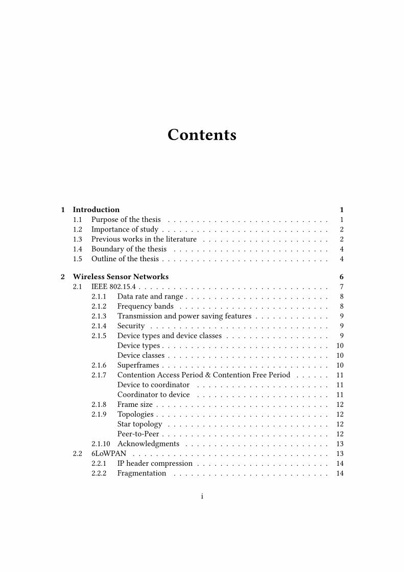
Contents
1 Introduction 11.1 Purpose of the thesis . . . . . . . . . . . . . . . . . . . . . . . . . . . . 1
1.2 Importance of study . . . . . . . . . . . . . . . . . . . . . . . . . . . . . 2
1.3 Previous works in the literature . . . . . . . . . . . . . . . . . . . . . . 2
1.4 Boundary of the thesis . . . . . . . . . . . . . . . . . . . . . . . . . . . 4
1.5 Outline of the thesis . . . . . . . . . . . . . . . . . . . . . . . . . . . . . 4
2 Wireless Sensor Networks 62.1 IEEE 802.15.4 . . . . . . . . . . . . . . . . . . . . . . . . . . . . . . . . . 7
2.1.1 Data rate and range . . . . . . . . . . . . . . . . . . . . . . . . . 8
2.1.2 Frequency bands . . . . . . . . . . . . . . . . . . . . . . . . . . 8
2.1.3 Transmission and power saving features . . . . . . . . . . . . . 9
2.1.4 Security . . . . . . . . . . . . . . . . . . . . . . . . . . . . . . . 9
2.1.5 Device types and device classes . . . . . . . . . . . . . . . . . . 9
Device types . . . . . . . . . . . . . . . . . . . . . . . . . . . . . 10
Device classes . . . . . . . . . . . . . . . . . . . . . . . . . . . . 10
2.1.6 Superframes . . . . . . . . . . . . . . . . . . . . . . . . . . . . . 10
2.1.7 Contention Access Period & Contention Free Period . . . . . . 11
Device to coordinator . . . . . . . . . . . . . . . . . . . . . . . 11
Coordinator to device . . . . . . . . . . . . . . . . . . . . . . . 11
2.1.8 Frame size . . . . . . . . . . . . . . . . . . . . . . . . . . . . . . 12
2.1.9 Topologies . . . . . . . . . . . . . . . . . . . . . . . . . . . . . . 12
Star topology . . . . . . . . . . . . . . . . . . . . . . . . . . . . 12
Peer-to-Peer . . . . . . . . . . . . . . . . . . . . . . . . . . . . . 12
2.1.10 Acknowledgments . . . . . . . . . . . . . . . . . . . . . . . . . 13
2.2 6LoWPAN . . . . . . . . . . . . . . . . . . . . . . . . . . . . . . . . . . 13
2.2.1 IP header compression . . . . . . . . . . . . . . . . . . . . . . . 14
2.2.2 Fragmentation . . . . . . . . . . . . . . . . . . . . . . . . . . . 14
i
CONTENTS
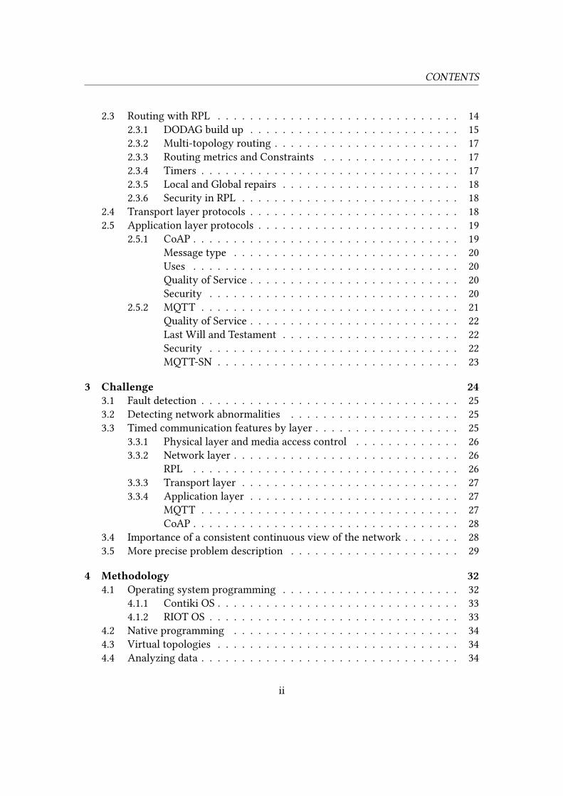
2.3 Routing with RPL . . . . . . . . . . . . . . . . . . . . . . . . . . . . . . 14
2.3.1 DODAG build up . . . . . . . . . . . . . . . . . . . . . . . . . . 15
2.3.2 Multi-topology routing . . . . . . . . . . . . . . . . . . . . . . . 17
2.3.3 Routing metrics and Constraints . . . . . . . . . . . . . . . . . 17
2.3.4 Timers . . . . . . . . . . . . . . . . . . . . . . . . . . . . . . . . 17
2.3.5 Local and Global repairs . . . . . . . . . . . . . . . . . . . . . . 18
2.3.6 Security in RPL . . . . . . . . . . . . . . . . . . . . . . . . . . . 18
2.4 Transport layer protocols . . . . . . . . . . . . . . . . . . . . . . . . . . 18
2.5 Application layer protocols . . . . . . . . . . . . . . . . . . . . . . . . . 19
2.5.1 CoAP . . . . . . . . . . . . . . . . . . . . . . . . . . . . . . . . . 19
Message type . . . . . . . . . . . . . . . . . . . . . . . . . . . . 20
Uses . . . . . . . . . . . . . . . . . . . . . . . . . . . . . . . . . 20
Quality of Service . . . . . . . . . . . . . . . . . . . . . . . . . . 20
Security . . . . . . . . . . . . . . . . . . . . . . . . . . . . . . . 20
2.5.2 MQTT . . . . . . . . . . . . . . . . . . . . . . . . . . . . . . . . 21
Quality of Service . . . . . . . . . . . . . . . . . . . . . . . . . . 22
Last Will and Testament . . . . . . . . . . . . . . . . . . . . . . 22
Security . . . . . . . . . . . . . . . . . . . . . . . . . . . . . . . 22
MQTT-SN . . . . . . . . . . . . . . . . . . . . . . . . . . . . . . 23
3 Challenge 243.1 Fault detection . . . . . . . . . . . . . . . . . . . . . . . . . . . . . . . . 25
3.2 Detecting network abnormalities . . . . . . . . . . . . . . . . . . . . . 25
3.3 Timed communication features by layer . . . . . . . . . . . . . . . . . . 25
3.3.1 Physical layer and media access control . . . . . . . . . . . . . 26
3.3.2 Network layer . . . . . . . . . . . . . . . . . . . . . . . . . . . . 26
RPL . . . . . . . . . . . . . . . . . . . . . . . . . . . . . . . . . 26
3.3.3 Transport layer . . . . . . . . . . . . . . . . . . . . . . . . . . . 27
3.3.4 Application layer . . . . . . . . . . . . . . . . . . . . . . . . . . 27
MQTT . . . . . . . . . . . . . . . . . . . . . . . . . . . . . . . . 27
CoAP . . . . . . . . . . . . . . . . . . . . . . . . . . . . . . . . . 28
3.4 Importance of a consistent continuous view of the network . . . . . . . 28
3.5 More precise problem description . . . . . . . . . . . . . . . . . . . . . 29
4 Methodology 324.1 Operating system programming . . . . . . . . . . . . . . . . . . . . . . 32
4.1.1 Contiki OS . . . . . . . . . . . . . . . . . . . . . . . . . . . . . . 33
4.1.2 RIOT OS . . . . . . . . . . . . . . . . . . . . . . . . . . . . . . . 33
4.2 Native programming . . . . . . . . . . . . . . . . . . . . . . . . . . . . 34
4.3 Virtual topologies . . . . . . . . . . . . . . . . . . . . . . . . . . . . . . 34
4.4 Analyzing data . . . . . . . . . . . . . . . . . . . . . . . . . . . . . . . . 34
ii

CONTENTS
4.5 Devices . . . . . . . . . . . . . . . . . . . . . . . . . . . . . . . . . . . . 35
4.5.1 Border router . . . . . . . . . . . . . . . . . . . . . . . . . . . . 35
4.5.2 Local coordinator . . . . . . . . . . . . . . . . . . . . . . . . . . 36
4.5.3 End device . . . . . . . . . . . . . . . . . . . . . . . . . . . . . . 36
5 Design of the proposed method 375.1 Method proposed in the thesis . . . . . . . . . . . . . . . . . . . . . . . 38
5.1.1 Time aspect . . . . . . . . . . . . . . . . . . . . . . . . . . . . . 39
5.1.2 Message complexity . . . . . . . . . . . . . . . . . . . . . . . . 40
5.1.3 Algorithm description . . . . . . . . . . . . . . . . . . . . . . . 40
6 Results 426.1 Simulated network topology . . . . . . . . . . . . . . . . . . . . . . . . 42
6.2 Message complexity . . . . . . . . . . . . . . . . . . . . . . . . . . . . . 42
6.3 Responsiveness . . . . . . . . . . . . . . . . . . . . . . . . . . . . . . . 43
6.4 Energy-e�ciency . . . . . . . . . . . . . . . . . . . . . . . . . . . . . . 44
6.5 False positives . . . . . . . . . . . . . . . . . . . . . . . . . . . . . . . . 45
7 Discussion 477.1 Energy consumption . . . . . . . . . . . . . . . . . . . . . . . . . . . . 47
7.2 Authentication . . . . . . . . . . . . . . . . . . . . . . . . . . . . . . . . 48
7.3 Multi DODAG for safety-critical devices . . . . . . . . . . . . . . . . . 48
7.4 Direct inter end node communications . . . . . . . . . . . . . . . . . . 49
7.5 Related works . . . . . . . . . . . . . . . . . . . . . . . . . . . . . . . . 50
7.6 Open issues and future works . . . . . . . . . . . . . . . . . . . . . . . 50
8 Conclusions 52
Bibliography 53
iii
List of Figures
2.1 IEEE 802.15.4 Star and Peer-to-Peer topologies.
Attribution: This �gure is taken from Wikipedia - The Free Encyclopedia and has
been released to the public domain.
http://commons.wikimedia.org/wiki/File:IEEE_802.15.4_Star_P2P.svg . . 12
2.2 The "rippling"-like distribution of the DIO message in RPL. . . . . . . . 16
2.3 Two subscriptions followed by an one-to-many publication. . . . . . . 21
4.1 A virtual topology with six TAP interfaces and �ve links with customiz-
able link loss rate. . . . . . . . . . . . . . . . . . . . . . . . . . . . . . . 35
5.1 The round-robin keep-alive message �ow. . . . . . . . . . . . . . . . . 38
6.1 The simulated topology where the two end nodes are distanced from
the PAN coordinator through the intermediary of a local coordinator. . 43
6.2 Probability of failed round . . . . . . . . . . . . . . . . . . . . . . . . . 46
6.3 Probability of failure for three consecutive rounds . . . . . . . . . . . . 46
7.1 Inter end node communication would fail to test the direct upward link
for intermediate end nodes. . . . . . . . . . . . . . . . . . . . . . . . . . 49
iv
List of Tables
2.1 A representation of the technologies and the corresponding layer. . . . 7
3.1 Table showing possible outcome in case of node or link failure. . . . . . 29
4.1 Comparison of the Contiki and RIOT operating systems. . . . . . . . . 33
v

1
Introduction
T
he Internet of Things (IoT) is the colloquial term for the interconnection
of objects or "things", to the existing Internet infrastructure. These devices,
usually small embedded computational devices, will transform our concept of
Internet connectivity. By equipping objects such as cars, laundry machines,
in-door heating systems, and even our-selves with Internet capabilities, the way that
we will interact with these objects and how these objects will interact with each-other
will change drastically.
In this new era of technology, it is expected that Wireless Sensor Networks (WSN)
will play a key role in the information exchange between embedded devices and the
Internet. However, wireless communications are not without obstacles and as we allow
objects to become connected to the Internet, e�orts must be taken to ensure reliable
communication given any external impacts such as interference or absorption.
1.1 Purpose of the thesisFuture homes will be able to o�er a range of di�erent smart services, e.g. energy, utility,
entertainment, medical, and security [1], all of which require a reliable way to transfer
information and a way to detect abnormalities such as the disconnection of nodes or
interference. All wireless networks are a�ected by interference which makes timed
deliveries hard to achieve. As for wireless sensor networks, not only is it prone to in-
terference, but the network could also experience changes in its topology. Nodes might
crash, or be physically moved which will result in changes in the network’s topology.
Therefore, it is important to consider these asynchronous and dynamic factors in the
network.
The purpose of this thesis is to examine and review the currently emerging proto-
1
1.2. IMPORTANCE OF STUDY CHAPTER 1. INTRODUCTION
cols and technologies together with the generally assumed uses of IoT in smart home
environments and propose a method for addressing the unknown state problem, where
embedded devices may be asleep for long duration of time in order to prolong their
battery-life, but which introduces the uncertainty to whether the device is asleep, or
if by any other means unable to communicate, such as due to device or link failure.
Some devices are meant to be purely event-driven, that is, they are only to com-
municate when an event has transpired, this include many detector type devices, such
as intrusion detection and smoke detection. As such, other means needs to be taken
to ensure that the devices are at full operational capacity when they are not actively
transmitting, such as by a time-scheduled keep-alive function. With this however, other
problems arises, such as how to maintain low battery-consumption among all devices
in the network, as increased utilization of the wireless media will elongate wait times
according to CSMA/CA.
1.2 Importance of studyThe study of fault detection in distributed computing can be traced back to the early
onset of computer networks and the the study of Byzantine faults [2]. These funda-
mental principles of fault tolerance and fault detection are immensely applicable for
WSN, as wireless communications with battery-operated nodes are at high risk at be-
ing exposed to both communication and hardware malfunction.
Currently, a lot of research within the IoT �eld is carried out, both within academia
and the industry sector. However, much of the development has been carried out in-
dependently where subtle di�erences in the implementations has introduced compati-
bility issues between operating systems for WSN, which may lead to sub-optimal per-
formance in networks consisting of nodes that are running di�erent operating sys-
tems [3] [4]. Also, as many of the protocols associated with IoT are not yet fully
standardized, di�erent implementations relying on di�erent versions of the protocols’
draft, could potentially cause interoperability issues [5].
This thesis presents the unknown state problem in Wireless Sensor Networks, and
gives an abstract approach on combating the problem while adhering to the require-
ments and minimalist nature of WSN, and show how this could be implemented as an
application layer algorithm, independently of the underlying operative system.
1.3 Previous works in the literatureWorks on fault tolerance and fault detection in wireless sensor networks have pre-
viously been carried out by among others [6] [7]. A common denominator for these
previous works are that they try to �nd algorithms that are both fault-tolerant as well
2
1.3. PREVIOUS WORKS IN THE LITERATURE CHAPTER 1. INTRODUCTION
as energy e�cient, as fault tolerance can not come at a high energy cost since long op-
eration time by battery-operated nodes are of high concern. High redundancy, with the
option of powering down the redundant nodes has been suggested [8] [9], but which
would inadvertently lead to the higher installation cost and increased complexity of
the network. Moreover, evaluation and e�orts on fault tolerance mechanisms for WSN
standards IEEE 802.15.4 and ZigBee have been presented [10] [11].
Many approaches to achieving both energy e�ciency and data consistency have
been suggested. The Alep protocol suggested in [12], is an adaptive, lazy, and energy-
e�cient protocol that relies on aggregating data and delaying deliveries to reach energy-
e�ciency.
On the topic of safety-critical devices, [13] showcases a wireless �re-alarm setting,
in where an alarm must be reported to a control station within ten seconds, detection
of faulty nodes must occur within �ve minutes, and have a network lifetime of 3-5
years.
The authors at [14] show strategies for heartbeat-style failure detection where gos-
siping schemes with �xed message transmission rate are used for failure detection. The
heartbeat-style gossiping schemes are proposed as routing protocol independent and
make use of local broadcast to propagate a heartbeat counter. Due to this, information
propagates slowly and at high cost. The paper acknowledge the fact that little research
exists as to where probabilistically a lower bound should be drawn as to when to judge
if a node has crashed. The suggested approach is robust, but the requirements on ac-
curacy is an open issue, as the trade-o� between higher accuracy results in increased
latency for the failure detection system.
Another e�ort is the Memento system introduced by [15] that provides failure de-
tection and symptom alerts, with limited bandwidth and power usage. Although ef-
fective, this more-advanced approach show considerable detection times when mini-
mizing the false failure reports.
Still, the works of Meier [13] provides in-depth insight to the handling of safety-
critical devices in WSN and introduces both a monitoring scheme as well as a forward-
ing algorithm that show results in simulation and implementation with high on-time
delivery ratio, prompt failure reporting, and long network life time. The monitoring
scheme called DiMo, is a distributed node monitoring scheme that maintains the net-
work topology and monitors the health status of nodes. As such, DiMo does not rely
on any routing protocol, but rather in an e�ort to increase e�ciency and minimize en-
ergy consumption, the tasks of keeping a network topology and monitoring the health
status of nodes is combined. This approach is suitable for a network that only consists
of safety-critical devices, where no regular data tra�c from other devices are expected.
The algorithm monitors the network using observer nodes, which receives heartbeat
messages from monitored nodes, and if it does not receive a heartbeat within a prede-
termined time, it will send a report message to the sink. The observer node will also
3

1.4. BOUNDARY OF THE THESIS CHAPTER 1. INTRODUCTION
check the liveliness of the link towards the sink and as such the selection of observer
nodes are alternated between relay nodes in the network to maximize network lifetime.
Algorithm shows great reduction in the number of false positives reported as well as
in the worst-case latency to report missing nodes compared to the Memento [15] al-
gorithm. However, DiMo was designed with a target at �ve minutes as the maximum
error reporting delay, and follows a rather uniformly time distributed detection time
between the order of 30 seconds to 260 seconds. In the simulation-based evaluation,
it was able to detect all missing nodes within �ve minutes, although very few were
detected within the �rst 30 seconds.
1.4 Boundary of the thesisThe Internet of Things consists of many things, with Wireless Sensor Networks being
present in smart grids, smart cities, industrial settings and others. This thesis will be
focused on the home environment and Smart Home implementations, with an assumed
number of nodes of about 10 to 100 nodes in a home WSN. As wireless sensor networks
has many applications of use, of which implementation might be di�erent to that of
smart homes, it is important to make the distinction, as WSNs present in other settings
and containing a greater number of nodes will have other concerns and di�culties to
overcome.
1.5 Outline of the thesisThe outline of the thesis is as follows:
Chapter 2: Wireless Sensor Networks serves as a guide to the current technolo-
gies and protocols that have been developed to give a basis for IoT and Smart Home
devices. The chapter focuses on the IEEE 802.15.4 standard, the 6LoWPAN network-
ing protocol, the routing protocol RPL, and the application layer protocols CoAP and
MQTT.
Chapter 3: Challenge presents the unknown state problem and investigates how the
current protocols are set up to handle the obstacle of monitoring safety-critical devices
given the energy-restricted nature of WSN.
Chapter 4: Methodology serves to illustrate which tools are used in the develop-
ment of WSN and IoT devices. It describes the operating system programming ap-
proach to developing WSN software, how native programming is used to test software
4

1.5. OUTLINE OF THE THESIS CHAPTER 1. INTRODUCTION
and classi�es the device types, which is used to build and test the proposed algorithm
given in the subsequent chapters.
Chapter 5: Design of the proposedmethod provides an approach to the unknownstate problem based on a round-robin message �ow as to limit the total amount of mes-
sages required to carry out a keep-alive sequence. By utilizing end nodes to forward
the keep-alive message to other end nodes, the total number of messages required per
keep-alive round can be drastically reduced as compared to a fully centrally coordi-
nated keep-alive sequence.
Chapter 6: Results gives the simulated results of the implemented algorithm in-
troduced in the Design Chapter by using the RIOT OS as the base operating system,
together with the virtual topology tool Desvirt. The simulation environment provides
proof-of-concept for the algorithm and facilitates data on message complexity to be
visualized.
Chapter 7: Discussion investigates the possible obstacles and short-comings of the
designed algorithm in accordance to the speci�cation of wireless sensor networks.
Items such as power consumption and security is discussed. By the end of the chapter
some open issues are mentioned.
Chapter 8: Conclusions delivers some concluding remarks about the thesis.
5
2
Wireless Sensor Networks
T
he Internet of Things can be deployed using any Internet capable technology,
such as Wi-Fi, Ethernet, or cellular networks. These technologies are all well
established and fully functional for Internet communications and as such are
suitable to be a part of the backbone of the Internet of Things. However,
the requirements of the Internet of Things di�erentiate from the current use of PCs,
laptops, smart phones and other peripherals that are connected to the Internet.
Firstly, for general Internet use the increase of bandwidth has been a corner stone
in development of the services associated with the web 2.0, such as streaming media,
cloud storage, and remote applications. For the Internet of Things however, the indi-
vidual bandwidth requirement per device is low, as most devices will only collect and
send sensory data, or receive actuating data [16].
Secondly, IoT devices do not require a user interface as what is normally expected
when working with connected devices. Rather, IoT devices are capable to function and
make decisions without human intervention. Devices may collect data, the data might
then be processed by some application and a suitable action could then be executed
accordingly to some pre-con�gured algorithm or self learned pattern recognition soft-
ware.
As a third di�erentiating factor, the scale of the Internet of Things will be much
greater than that of current connected devices, which will require an Internet backbone
capable of handling a large amount of devices. The Cisco Internet Business Solutions
Group (IBSG) predicts that the number of connected devices could be as high as 50
billion by 2020 [17], of which a majority is assumed to be small and constrained de-
vices. Other estimates include Gartner’s [18], which predicts there to be a total of 4.9
billion connected things in 2015, and total of 25 billion by the year 2020. With all IPv4
addresses being exhausted [19], the rapid expected growth of the Internet of Things
means that the roll-out of IPv6 is ever so important in order to accommodate for the
6
2.1. IEEE 802.15.4 CHAPTER 2. WIRELESS SENSOR NETWORKS
Internet of Things.
Wireless Sensor Networks usually consists of a number of battery powered sensor
and actuator devices, which are typically constrained in terms of storage and process-
ing power. For example, there exists a number of di�erent devices with dimensions
comparable to that of common circulating coin or less, equipped with as little as 1 kB
of RAM and 8 kB of �ash memory [20]. These types of devices are known as sensornodes, or in some cases as motes.
Wireless communication has the advantage of being easy to implement in already
constructed buildings, as it requires no extra installation of wires. As devices are not
bound by wires, they can also move freely around the building, making wireless com-
munication ideal for wearable items and other none stationary devices.
This chapter will focus on a subset of technologies and protocols used with Wireless
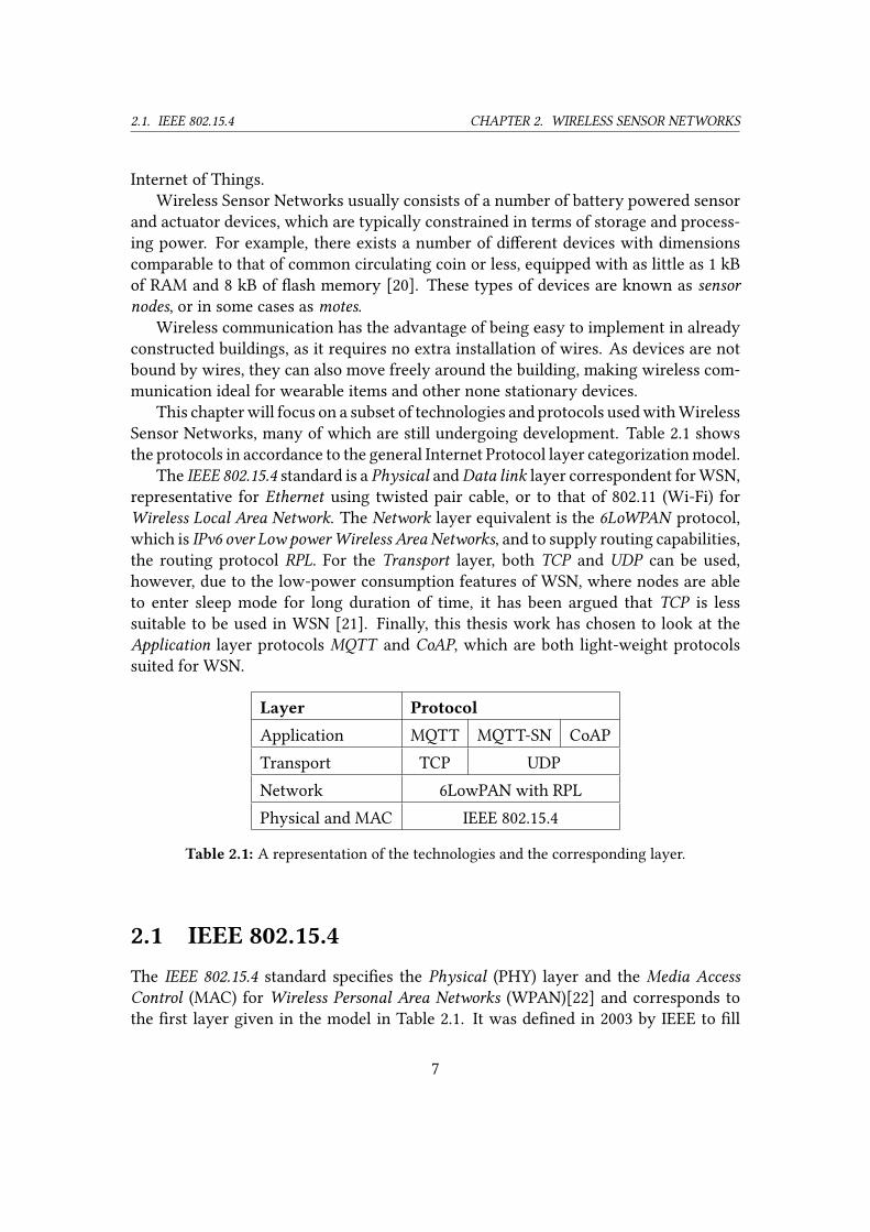
Sensor Networks, many of which are still undergoing development. Table 2.1 shows
the protocols in accordance to the general Internet Protocol layer categorization model.
The IEEE 802.15.4 standard is a Physical andData link layer correspondent for WSN,
representative for Ethernet using twisted pair cable, or to that of 802.11 (Wi-Fi) for
Wireless Local Area Network. The Network layer equivalent is the 6LoWPAN protocol,
which is IPv6 over Low powerWireless Area Networks, and to supply routing capabilities,
the routing protocol RPL. For the Transport layer, both TCP and UDP can be used,
however, due to the low-power consumption features of WSN, where nodes are able
to enter sleep mode for long duration of time, it has been argued that TCP is less
suitable to be used in WSN [21]. Finally, this thesis work has chosen to look at the
Application layer protocols MQTT and CoAP, which are both light-weight protocols
suited for WSN.
Layer Protocol
Application MQTT MQTT-SN CoAP
Transport TCP UDP
Network 6LowPAN with RPL
Physical and MAC IEEE 802.15.4
Table 2.1: A representation of the technologies and the corresponding layer.
2.1 IEEE 802.15.4The IEEE 802.15.4 standard speci�es the Physical (PHY) layer and the Media AccessControl (MAC) for Wireless Personal Area Networks (WPAN)[22] and corresponds to
the �rst layer given in the model in Table 2.1. It was de�ned in 2003 by IEEE to �ll
7
2.1. IEEE 802.15.4 CHAPTER 2. WIRELESS SENSOR NETWORKS
a gap in existing wireless network standards. IEEE constructed the standard with the
following set of criteria [22]:
• Very low complexity
• Support for multiple-node networks
• Ultra low power consumption
• Low data-rate
• Relatively short communication range
• Using unlicensed radio bands
• Low Cost
With these criteria the standard is set aside from other wireless standards such as
the 802.15.1 (Bluetooth) which is intended for point-to-point communications and not
for multiple-node networks, and from the 802.15.3 which is designed as a High Rate
WPAN.
Primarily, the 802.15.4 standard is devised for very low power consumption, mak-
ing it possible to make use of battery-powered devices which are totally wireless (equipped
with neither network or power cables) for easy and cost-e�cient installations.
2.1.1 Data rate and rangeThe standard has a maximum data-rate of 250 kbit/s depending on which modula-
tion scheme and frequency band that is used. The range is dependent on operating
environment as well as output power of the antennas, which usually is kept low in
battery-operated devices to conserve power. Typical ranges are above 200 meters for
outdoor uses and about 30 meters in indoor uses depending on factors such as absorp-
tion, re�ection and di�raction due to walls and other objects [22].
2.1.2 Frequency bandsThe IEEE 802.15.4 de�nes two di�erent PHYs, one to be used with regional bands and
one PHY for the global 2.4 GHz frequency band. The two original regional frequency
bands are 868.0-868.6 MHz for Europe which only has one channel numbered as 0 and
the 902-928 MHz for North America which is divided in to ten channels numbered 1
to 10. Since the original speci�cation, more regional frequency bands has been added
through amendments to the standard to be used in China and Japan. The worldwide
band of 2400-2483.5 MHz is divided into 16 channels numbered 11 to 26. As the global
8
2.1. IEEE 802.15.4 CHAPTER 2. WIRELESS SENSOR NETWORKS
2.4 GHz band is commonly used for other communication systems, such as Wi-Fi,
Bluetooth and cordless phones, it is important to choose a suitable channel, as to avoid
potential disturbances from other communications.
2.1.3 Transmission and power saving featuresMost of a node’s power usage will correspond to the amount of time it spends on listen-
ing or transmitting data [23] [24] [25]. IEEE 802.15.4 make use of very low duty cycles
to keep the transmission times short. A duty cycle is de�ned as the time interval for
when the node is transmitting or is actively listening on the network, which is then
followed by a long interval of no transmission or listening. By making the duty cycles
short, and the time intervals between the transmitting and listening phase long, power
is conserved, as the node is able to enter a low-power sleep mode between duty cy-
cles. As a direct consequence of this, nodes are not able to receive transmissions while
in sleep mode, messages intended for sleeping nodes are therefore stored, and later
retrieved by the receiving node by sending a request message for incoming messages
when it enters the duty cycle.
2.1.4 SecurityThe standard has built-in security services, as it can optionally use Block Cipher Modeto encrypt the tra�c. It can be con�gured to either use Counter Mode (CTR) or Cipher-block Chaining (CBC) with AES, but key management must be provided by higher
layers. The 802.15.4 frames contains Frame Control Fields and sequence numbers and
as such, these cryptographic mechanisms will provide the security services of DataCon�dentiality, Data Authenticity and Replay Protection when in use.
Using a link-layer level security has the advantages of being hardware realisable
and being network protocol independent. However, link-layer security will only pro-
vide security on a hop-by-hop basis, meaning that every node that the message passes
through must be a trusted node, and if the message leaves the 802.15.4 network the
link-level security will no longer be available, thus an end-to-end security can not be
achieved purely by using link-layer security.
2.1.5 Device types and device classesNodes are divided into Device Types according to their functionalities and into DeviceClasses according to their capabilities.
9
2.1. IEEE 802.15.4 CHAPTER 2. WIRELESS SENSOR NETWORKS
Device types
There must be one and only one PAN Coordinator in an 802.15.4 network. The PAN
Coordinator assigns a PAN ID to the network, and assigns itself a short address. It
handles requests from other devices which wishes to join the network and assigns
them a short address. It is also responsible of performing an energy scan to select
the most suitable channel to use for communications. Depending on the topology
used, it also relays all or some of the messages sent. In practice, the coordinator is
the edge of the network, and bridges the network towards the Internet. Given that the
coordinator make use of another network interface which may or may not be incapable
of supporting sleep mode, and given the communication �ow of 802.15.4 networks,
which in some cases does not support the PAN coordinator to enter sleep-mode, this
device type requires more power usage than other nodes in the network, making it
less suitable to run on battery.
The local coordinator, also known as the router, is a device capable of relaying
messages from and to other nodes. In a network there can exist many local coordina-
tors, each with the capabilities of handling requests when other nodes wishes to join
the network or relay their messages.
The end devices are nodes connected to either a PAN Coordinator or Local Coordi-
nator, which are not able to relay other nodes messages. Usually, these are low-power
consuming devices, which have a high sleep to work ratio, and are only set to wake
up to handle incoming messages or transmit data. In essence, these end devices can be
battery-powered with a very long battery-operating time [26].
Device classes
The device class Full Function Device (FFD) is capable of being a PAN coordinator
or a local coordinator as well as an end device. All PAN coordinators and local coordi-
nators must be an FFD.
The device class Reduced Function Device (RFD) has a simpler subset of the
802.15.4 protocol, with restricted processing and memory resources, making it inca-
pable to act as a PAN coordinator or local coordinator.
2.1.6 SuperframesThe standard has the optional functionality of using superframes. The superframe is
de�ned by the PAN coordinator which transmits network beacons where the interval
between the beacons is divided into 16 equally sized time slots. Such a network is
referred to as a beacon-enabled network. There is also another mode where the super-
frame is enlarged by an inactive period, allowing for the coordinator to enter low-
power mode during the inactive period.
10
2.1. IEEE 802.15.4 CHAPTER 2. WIRELESS SENSOR NETWORKS
2.1.7 Contention Access Period & Contention Free PeriodAny device that wishes to communicate in a beacon-enabled network will do so during
the Contention Access Period (CAP) between two beacons. All devices are using slotted
CSMA/CA, which does not guarantee timed transmissions. There is however a func-
tion, named Guaranteed Time Slots (GTS) which takes place during a period known as
the Contention Free Period (CFP) which the coordinator may choose to use. The coor-
dinator may allocate up to seven GTSs in a CTS which takes place right after the CAP.
In the CFP, the coordinator may allocate a certain GTS for one speci�c device, making
that device the only device allowed to communicate during that GTS. This guarantees
that the device will always be able to communicate during its GTS in every superframe.
The use of GTSs is suitable for nodes which require low-latency or a speci�c amount
of data bandwidth.
Device to coordinator
In beacon-enabled networks, a device that wishes to send a message �rst needs to listen
for the network beacon. When the device receives a beacon, it becomes synchronized
with the beacon-enabled network. The device will then transmit its message to the
coordinator using slotted CSMA/CA or simply send the message during its allocated
GTS if in use.
In a nonbeacon-enabled network however, the nodes will simply engage in unslot-
ted CSMA/CA whenever it wishes to transmit a message.
Coordinator to device
As an end device might be in sleep-mode, the coordinator can not simply transmit a
data message to the device. In a beacon-enabled network, the coordinator will indicate
that there is a data message pending for a device in the network beacon. End devices
are not obliged to listen to every network beacon, so the coordinator will keep the data
message and the indication in the network beacon until the device receives the beacon.
When the device receives the network beacon, it will transmit a Data Request message
to the coordinator, using slotted CSMA/CA, after which the coordinator will send the
data message to the device.
For nonbeacon-enabled networks, the coordinator will store the data message and
wait for the device to make contact. Devices will periodically send a Data Requestmessage to the coordinator, to which the coordinator will respond with an acknowl-
edgment frame indicating whether there is a pending message, in which case it will
transmit the data message using unslotted CSMA/CA.
11

2.1. IEEE 802.15.4 CHAPTER 2. WIRELESS SENSOR NETWORKS
2.1.8 Frame size802.15.4 only support a maximum frame size of 127 bytes. After accounting for the
frame header, and optional link-layer security, even less is available for the layers
above. This requires that the upper layers are well-suitable for small frame size trans-
missions, in order to avoid unnecessary link-layer fragmentation. Also, when consid-
ering that the protocol should attain ultra low power consumption, every extra byte
that is required to be transmitted due to protocol-speci�c headers, can be directly trans-
lated in to a higher power utilization. For example, the IPv6 header is 40 bytes long,
which would leave little space left for the application data and thus requiring more
frames to be sent if the application data is larger than the available space left after
applying the headers.
2.1.9 Topologies
Figure 2.1: IEEE 802.15.4 Star and Peer-to-Peer
topologies.
Every 802.15.4 network must consist
of at least two devices, of which one
and only one must be a PAN coordi-
nator. IEEE 802.15.4 networks can be
build as either Peer-to-Peer or as star
networks shown in Figure 2.1.
Star topology
Star Topology is a network type
where a central PAN coordinator is
directly connected to all other de-
vices which are end devices. All mes-
sages must be send to the coordina-
tor, which will then relay the message to its �nal destination. The disadvantages with
this kind of topology is that the coordinator becomes one central point of failure, if the
coordinator fails, no other messages can be delivered as there is no alternative route.
Also, the coordinator might become a bottleneck and cause congestion if there is a
large number of end devices. The network is also limited in physical size, as any end
device must be in radio vicinity of the PAN coordinator.
Peer-to-Peer
Peer-to-Peer, also known as mesh topology makes it possible for devices to commu-
nicate directly. Devices that are not within range can communicate with each other
by relaying the messages through intermediate devices, without the use of the PAN
coordinator. This reduces the bottleneck e�ect on the PAN coordinator as well as the
12

2.2. 6LOWPAN CHAPTER 2. WIRELESS SENSOR NETWORKS
message complexity. Since devices do not need to be directly connected to the PAN
coordinator, the physical range of the network can be much larger compared to a Star
Topology network. However, as nodes may route and handle messages that do not
originate from themselves or for which they are the end destination, these local co-
ordinators will consume more power. Not all devices are required to relay messages,
and relay paths can be calculated and recalculated according to preferences such as
battery-level.
Other topologies are possible, although not part of the IEEE 802.15.4 standard, they
may be implemented on higher layers by other protocols, such as 6LoWPAN.
2.1.10 AcknowledgmentsFrames can be sent with or without acknowledgment request. If the AcknowledgmentRequest �ag is set for a frame, the sender will wait for a predetermined amount of time
for the corresponding acknowledgment to be received.
If the transmission was indirect, that is, a data message that was preceded by a
Data Request message, and no acknowledgment was received, the coordinator will not
retransmit the frame, but the frame will remain in the transaction queue of the coor-
dinator and will only be sent if the coordinator receives a new data request command.
If such a command is received, the originating device will then retransmit the frame.
For direct transmissions, i.e. from device to coordinator, the device will repeat the
transmission of the frame if it does not receive the acknowledgment. The number of
times that it will retransmit the frame is set in a variable (de�nable in the range of
0 to 7 times, with the default value being 3 times). The retransmission will only be
attempted if it can be completed within the same portion of the superframe, that is,
the CAP or GTS in which the original transmission was made. If this is not possible,
the retransmission will be delayed until the same portion of the next superframe. If
the device has still not received an acknowledgment after its maximum amount of
retransmissions, the MAC sublayer will consider the transmission failed and will notify
the next upper layer of the failure.
2.2 6LoWPANUsing an Internet Protocol with 802.15.4 networks has many advantages. Resources
within the network will be available on the Internet without the need of translations.
Already well-proven and readily used protocols such as UDP, TCP, HTTP, FTP and so
forth can be used directly, which makes development easier.
Given the presumed growth of the number of connected devices, the only reason-
able option to comply with IP technology and have adequate amount of address space
for IoT is to make use of IPv6. Clearly, the Internet backbone must support IPv6 fully in
13
2.3. ROUTING WITH RPL CHAPTER 2. WIRELESS SENSOR NETWORKS
order to accommodate with the increased quantity of connected and address-requiring
devices. Even so, the usage of IPv6 in WSN presents some obstacles as to comply with
the constrained and minimalist nature of the underlying architecture.
The IPv6 speci�cation [27] requires that links support amaximum transmission unit(MTU) of at least 1280 bytes. This pose a problem since IEEE 802.15.4 has a maximum
frame size of 127 bytes, of which a considerable part is used for the frame overhead
and optional security features. For example, using the AES-CCM-128 security imple-
mentation for 802.15.4 could leave as little as 81 bytes for the upper layers [22].
In regards to this, the IPv6 over Low power Wireless Personal Area Networks (6LoW-
PAN) [28] speci�cation was formulated as a means to facilitate IPv6 networking on
constrained devices running 802.15.4. 6LoWPAN is in essence IPv6, with a few mod-
i�cations in order for it to run in Wireless Sensor Networks where the frame size is
much smaller than the minimum MTU of IPv6.
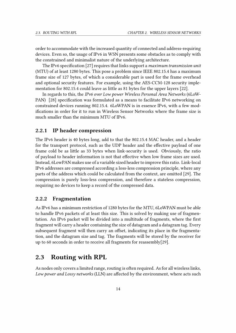
2.2.1 IP header compressionThe IPv6 header is 40 bytes long, add to that the 802.15.4 MAC header, and a header
for the transport protocol, such as the UDP header and the e�ective payload of one
frame cold be as little as 33 bytes when link-security is used. Obviously, the ratio
of payload to header information is not that e�ective when low frame sizes are used.
Instead, 6LowPAN makes use of a variable sized header to improve this ratio. Link-local
IPv6 addresses are compressed according a loss-less compression principle, where any
parts of the address which could be calculated from the context, are omitted [29]. The
compression is purely loss-less compression, and therefore a stateless compression,
requiring no devices to keep a record of the compressed data.
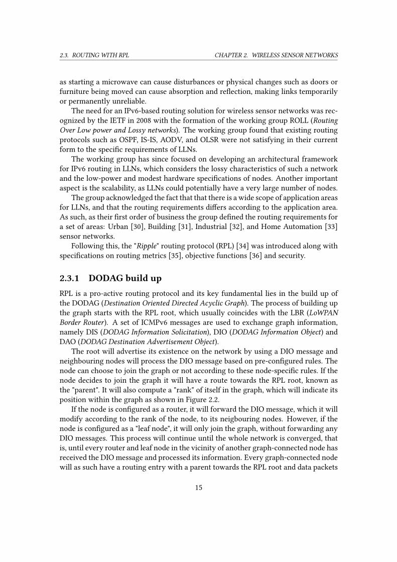
2.2.2 FragmentationAs IPv6 has a minimum restriction of 1280 bytes for the MTU, 6LoWPAN must be able
to handle IPv6 packets of at least this size. This is solved by making use of fragmen-
tation. An IPv6 packet will be divided into a multitude of fragments, where the �rst
fragment will carry a header containing the size of datagram and a datagram tag. Every
subsequent fragment will then carry an o�set, indicating its place in the fragmenta-
tion, and the datagram size and tag. The fragments will be stored by the receiver for
up to 60 seconds in order to receive all fragments for reassembly[29].
2.3 Routing with RPLAs nodes only covers a limited range, routing is often required. As for all wireless links,
Low power and Lossy networks (LLN) are a�ected by the environment, where acts such
14
2.3. ROUTING WITH RPL CHAPTER 2. WIRELESS SENSOR NETWORKS
as starting a microwave can cause disturbances or physical changes such as doors or
furniture being moved can cause absorption and re�ection, making links temporarily
or permanently unreliable.
The need for an IPv6-based routing solution for wireless sensor networks was rec-
ognized by the IETF in 2008 with the formation of the working group ROLL (RoutingOver Low power and Lossy networks). The working group found that existing routing
protocols such as OSPF, IS-IS, AODV, and OLSR were not satisfying in their current
form to the speci�c requirements of LLNs.
The working group has since focused on developing an architectural framework
for IPv6 routing in LLNs, which considers the lossy characteristics of such a network
and the low-power and modest hardware speci�cations of nodes. Another important
aspect is the scalability, as LLNs could potentially have a very large number of nodes.
The group acknowledged the fact that that there is a wide scope of application areas
for LLNs, and that the routing requirements di�ers according to the application area.
As such, as their �rst order of business the group de�ned the routing requirements for
a set of areas: Urban [30], Building [31], Industrial [32], and Home Automation [33]
sensor networks.
Following this, the "Ripple" routing protocol (RPL) [34] was introduced along with
speci�cations on routing metrics [35], objective functions [36] and security.
2.3.1 DODAG build upRPL is a pro-active routing protocol and its key fundamental lies in the build up of
the DODAG (Destination Oriented Directed Acyclic Graph). The process of building up
the graph starts with the RPL root, which usually coincides with the LBR (LoWPANBorder Router). A set of ICMPv6 messages are used to exchange graph information,
namely DIS (DODAG Information Solicitation), DIO (DODAG Information Object) and
DAO (DODAG Destination Advertisement Object).The root will advertise its existence on the network by using a DIO message and
neighbouring nodes will process the DIO message based on pre-con�gured rules. The
node can choose to join the graph or not according to these node-speci�c rules. If the
node decides to join the graph it will have a route towards the RPL root, known as
the "parent". It will also compute a "rank" of itself in the graph, which will indicate its
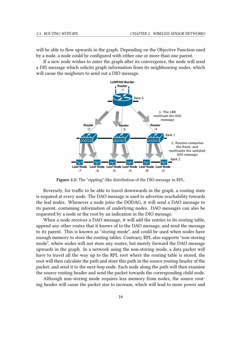
position within the graph as shown in Figure 2.2.
If the node is con�gured as a router, it will forward the DIO message, which it will
modify according to the rank of the node, to its neigbouring nodes. However, if the
node is con�gured as a "leaf node", it will only join the graph, without forwarding any
DIO messages. This process will continue until the whole network is converged, that
is, until every router and leaf node in the vicinity of another graph-connected node has
received the DIO message and processed its information. Every graph-connected node
will as such have a routing entry with a parent towards the RPL root and data packets
15
2.3. ROUTING WITH RPL CHAPTER 2. WIRELESS SENSOR NETWORKS
will be able to �ow upwards in the graph. Depending on the Objective Function used
by a node, a node could be con�gured with either one or more than one parent.
If a new node wishes to enter the graph after its convergence, the node will send
a DIS message which solicits graph information from its neighbouring nodes, which
will cause the neigbours to send out a DIO message.
Figure 2.2: The "rippling"-like distribution of the DIO message in RPL.
Reversely, for tra�c to be able to travel downwards in the graph, a routing state
is required at every node. The DAO message is used to advertise reachability towards
the leaf nodes. Whenever a node joins the DODAG, it will send a DAO message to
its parent, containing information of underlying nodes. DAO messages can also be
requested by a node or the root by an indication in the DIO message.
When a node receives a DAO message, it will add the entries to its routing table,
append any other routes that it knows of to the DAO message, and send the message
to its parent. This is known as "storing mode", and could be used when nodes have
enough memory to store the routing tables. Contrary, RPL also supports "non-storing
mode", where nodes will not store any routes, but merely forward the DAO message
upwards in the graph. In a network using the non-storing mode, a data packet will
have to travel all the way up to the RPL root where the routing table is stored, the
root will then calculate the path and store this path in the source routing header of the
packet, and send it to the next-hop node. Each node along the path will then examine
the source routing header and send the packet towards the corresponding child node.
Although non-storing mode requires less memory from nodes, the source rout-
ing header will cause the packet size to increase, which will lead to more power and
16
2.3. ROUTING WITH RPL CHAPTER 2. WIRELESS SENSOR NETWORKS
bandwidth consumption.
2.3.2 Multi-topology routingRPL has the added functionality to perform multi-topology routing (MTR). Basically,
using di�erent instances, multiple DODAGS can be constructed over the same phys-
ical topology, and associated with its own instance id. A node can belong to several
instances simultaneously, and tra�c could be directed using di�erent instances ac-
cording to the tra�c type. For example, non-critical tra�c can be routed to avoid
battery-powered nodes, whereas critical tra�c could be routed along the path with
the least amount of latency. Other parameters that could be taking into account when
building up multiple DODAGs are reliability, link-encryption support, battery-level,
and link color.
2.3.3 Routing metrics and ConstraintsRouting metrics and constraints [35] are used by RPL in an elaborated decision making
routing strategy to select the best available path according to set speci�cations. Metric
is a scalar quantity such as latency, battery-level, or reliability and could be either node
or link based. Constraints however, is a non-scalar criterion which is used to specify
which links and nodes that can be used when choosing the path, for example to only
include non-battery powered nodes in the path or links that can support encryption.
2.3.4 TimersWhereas regular routing protocols usually make use of periodic keepalive messages
to keep the routing tables up date, RPL needs to consider the energy-saving princi-
ples of LLNs and therefore limit the number of control messages sent. Instead, RPL
implements a self-regulating mechanism known as the "trickle timer" [36].
The trickle algorithm uses a variable timer that is the result of the current stability
of the network. Events, such as loops, or when a node joins or moves within the
network, are treated as inconsistencies in the network and will cause the timer variable
to decrease, giving rise to a higher frequency of DIO messages. In contrary, the lack of
inconsistencies in the network will allow the trickle timer to increase and subsequently
less DIO control messages will be sent.
As the trickle timer is implemented locally, any area of the network that exhibits
inconsistencies will have a higher rate of control messages in its vicinity, whereas other
areas without inconsistencies will have a lower rate of control messages.
17
2.4. TRANSPORT LAYER PROTOCOLS CHAPTER 2. WIRELESS SENSOR NETWORKS
2.3.5 Local and Global repairsRPL has graph repair mechanisms that allows nodes to take action to repair the graph
in case of link or node failures. If a node is unable to communicate with its parent, so
that it has no other route in the upward direction of the graph, it can initiate a localrepair. In a local repair, the node will try to �nd another parent, by sending out RPL
control messages.
This could however cause the graph to diverge from its most optimal con�gura-
tion, which is why a global repair is sometimes necessary. A global repair can only be
initiated by the RPL root and will rebuild the DODAG completely, at the high cost of
the number of messages required by such an action.
2.3.6 Security in RPLAs security adds an extra level of complexity and therefore adds to the requirements on
the hardware, it is not always feasible or desired to include elaborate security features
within the RPL implementation. However, there exists security features in RPL which
are available as optional extensions [34].
RPL has through these extensions three security modes; "unsecured", "pre-installed",
and "authenticated". In the unsecured mode, RPL messages are sent without any se-
curity. For the pre-installed mode, a pre-installed key is used which allows the nodes
to process and generate RPL messages within an RPL instance. In the authenticated
mode, nodes are required to obtain a key from an authentication authority if it joins
the instance as a forwarding node.
2.4 Transport layer protocolsSince 6LoWPAN gives wireless sensor networks IP connectivity, both TCP [37] and
UDP [38] may be used with 6LoWPAN networks. TCP however, has been often been
claimed as unsuitable for WSNs due to the speci�c requirements of the protocol [21].
As TCP is a connection-oriented protocol, a connection involving the three-way hand-
shake must �rst be set up before transferring any data. As sensor data is usually only
one value, corresponding to at most a few bytes of data, the overhead carried by TCP
is large in comparison to the data sent. The handshake procedure will also prolong
the transmission of the data, causing sensor data to arrive to its destination later than
if UDP was used. One option to reduce the overhead of the three-way handshake and
improve on the data latency, is to keep the connection open between transmissions.
This however, requires a constant exchange of keep alive messages, which would re-
quire a node to wake up from sleep mode to keep the connection alive, even if it has no
sensor data to send. This is not desirable when nodes are battery-powered and strive
to keep their awake/sleep ratio as low as possible in order to conserve power.
18
2.5. APPLICATION LAYER PROTOCOLS CHAPTER 2. WIRELESS SENSOR NETWORKS
UDP comes with its own set of disadvantages, for example, UDP o�ers no �ow
control or congestion control, which might cause dropped datagrams in a congested
network. Also, UDP contains no ACK mechanism.
In conclusion, one can argue that neither TCP nor UDP are suitable for WSNs,
however, as UDP is such a rudimentary protocol, carrying only a mere 8 byte header,
it makes up for its shortcomings due to its simplicity, as the extra functionalities of
TCP comes at the price of a higher complexity. Any shortcomings of UDP, such as
reliability and the lack of an ACK mechanism could be left to the Application Layer to
optionally implement.
2.5 Application layer protocolsCommon application layer protocols such as HTTP and FTP have not been constructed
for constrained environments in mind, as little e�ort has been made to keep the over-
head small. For WSNs, which are restricted in terms of bandwidth, energy, and hard-
ware, the need to keep the overhead low and the overall simplicity in terms of com-
plexity to the minimum viability, supersedes the approach of making communication
easily read by humans.
Two of the most discussed application protocols for Internet of Things deployment
are MQTT and CoAP [39]. Both are open standards which has been constructed with
constrained devices in mind. They are fundamentally di�erent from each other, as a
di�erent approach to communication has been taken for MQTT and CoAP respectively.
MQTT is a client-server setup, and make use of a so called broker which acts as a server,
whereas CoAP is a server-client setup, where every node that runs CoAP is a server
by its own.
2.5.1 CoAPThe Constrained Application Protocol (CoAP)[40] developed by the CoRE (ConstrainedRESTful Environments) IETF group is a transfer protocol similar to HTTP, but designed
for constrained devices. Rather than using TCP, CoAP relies on UDP for transport.
According to its speci�cation [40], CoAP has the following main features:
• Web protocol ful�lling M2M requirements in constrained environments
• UDP [RFC0768] binding with optional reliability supporting unicast and multi-
cast requests.
• Asynchronous message exchanges.
• Low header overhead and parsing complexity.
19
2.5. APPLICATION LAYER PROTOCOLS CHAPTER 2. WIRELESS SENSOR NETWORKS
• URI and Content-type support.
• Simple proxy and caching capabilities.
• A stateless HTTP mapping, allowing proxies to be built providing access to CoAP
resources via HTTP in a uniform way or for HTTP simple interfaces to be real-
ized alternatively over CoAP.
• Security binding to Datagram Transport Layer Security (DTLS) [RFC6347].
Message type
CoAp has two message types, the request message and the response message, with
�xed-size header, an optional Type-Length-Value for further options, and a payload.
The payload size is bound by the underlying datagram length of UDP.
Uses
In contrast to HTTP, CoAP has a built-in subscription and publishing mechanism,
known as observation, which allows clients to subscribe to resources and receive up-
dates when changes occur. Clients can do a resource search on available resources by
accessing the URI /.well-known/core on a CoAP server, which returns a list of
the available resources.
Quality of Service
Messages can be marked as "con�rmable" or "noncon�rmable", a con�rmable message
must be acknowledged whereas noncon�rmable messages are "�re and forget".
Security
As CoAP is a UDP protocol, TLS is not available since it requires a TCP connection.
However, the similar DTLS [41] (Datagram Transport Layer Security) can provide se-
curity for UDP, with support for AES and RSA. It has been showned in [42] that CoAP
with DTLS o�ers full protection against eavesdropping and man-in-the-middle attacks.
Another means to secure CoAP is with the use of IPsec, which unlike DTLS operates
directy at the network layer. As such, the CoAP implementation can be kept intact, as
IPsec is transparent to the application layer. However, IPsec requires support from
the underlying IP stack, which is not necessarily present in the IP stacks designed for
constrained devices.
20
2.5. APPLICATION LAYER PROTOCOLS CHAPTER 2. WIRELESS SENSOR NETWORKS
2.5.2 MQTTMQTT[43], formerly enlarged as Message Queue Telemetry Transport, is a lightweight
publish/subscribe messaging protocol originally developed by IBM but has since be-
come an open standard managed by OASIS.
(a) Subscription (b) Publishing
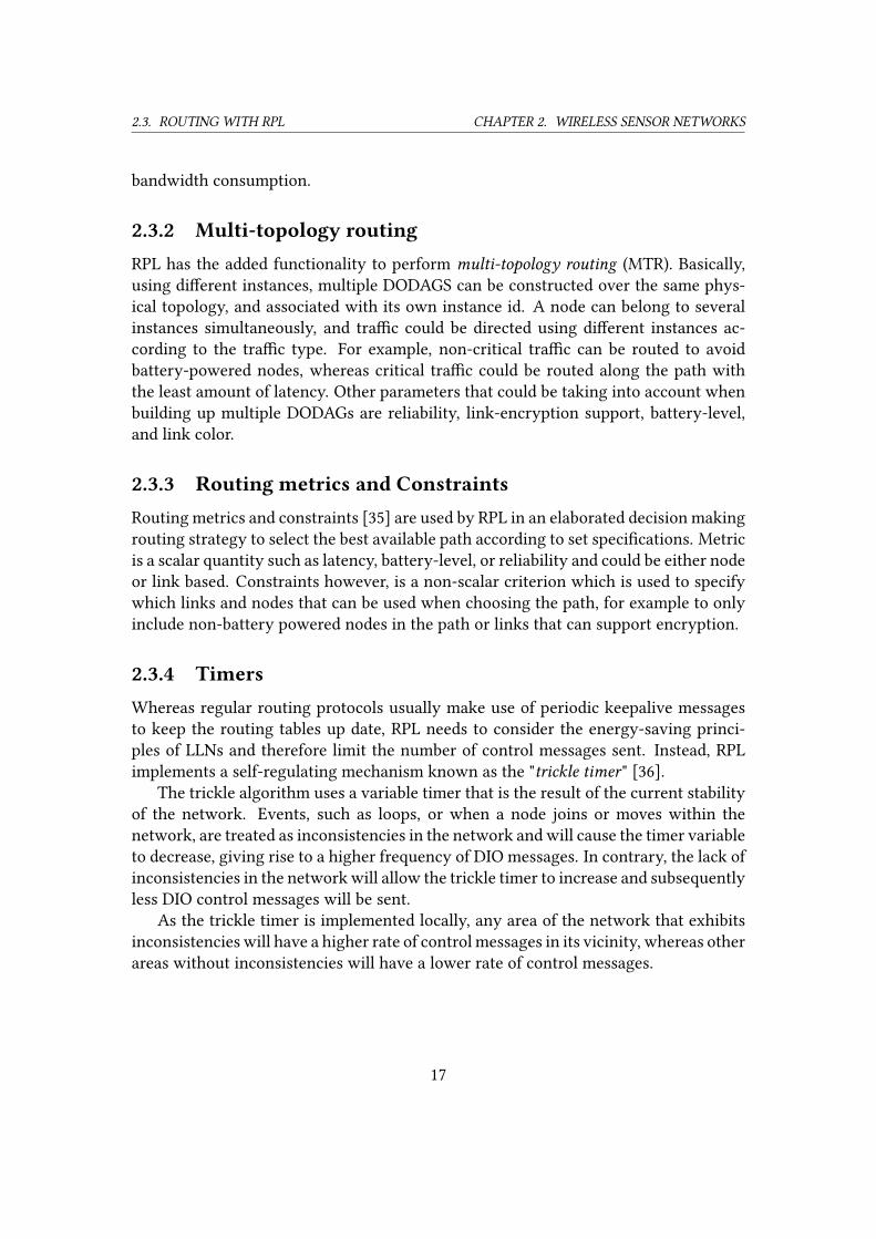
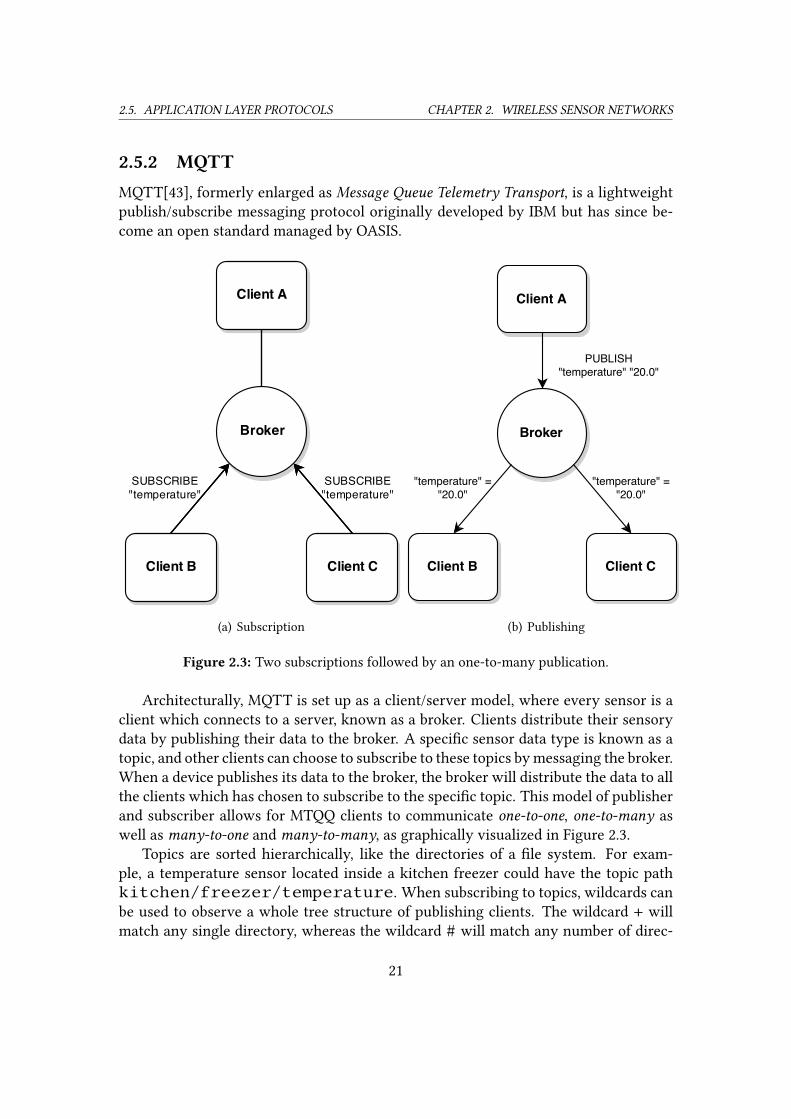
Figure 2.3: Two subscriptions followed by an one-to-many publication.
Architecturally, MQTT is set up as a client/server model, where every sensor is a
client which connects to a server, known as a broker. Clients distribute their sensory
data by publishing their data to the broker. A speci�c sensor data type is known as a
topic, and other clients can choose to subscribe to these topics by messaging the broker.
When a device publishes its data to the broker, the broker will distribute the data to all
the clients which has chosen to subscribe to the speci�c topic. This model of publisher
and subscriber allows for MTQQ clients to communicate one-to-one, one-to-many as
well as many-to-one and many-to-many, as graphically visualized in Figure 2.3.
Topics are sorted hierarchically, like the directories of a �le system. For exam-
ple, a temperature sensor located inside a kitchen freezer could have the topic path
kitchen/freezer/temperature. When subscribing to topics, wildcards can
be used to observe a whole tree structure of publishing clients. The wildcard + will
match any single directory, whereas the wildcard # will match any number of direc-
21
2.5. APPLICATION LAYER PROTOCOLS CHAPTER 2. WIRELESS SENSOR NETWORKS
tories. As such, subscribing to the topic kitchen/+/temperature will match
kitchen/freezer/temperature as well askitchen/fridge/temper-ature, but not kitchen/temperature or kitchen/dishwasher/wa-teroutlet/temperature. The # wildcard must be the �nal character of a sub-
scription, and will match any depth level, i.e. the subscription kitchen/# would
match all the previous examples.
Quality of Service
MQTT has three levels of assurance for delivery when publishing topics. These Qual-ity of Service levels are At most once (Fire and Forget), At least once (Acknowledged
delivery), and Exactly once (Assured delivery).
With At most once delivery, the message is delivered with the best e�orts of the
underlying layers. No response is expected and no retransmissions are carried out.
The client will publish the message to the broker and then simply delete the message.
The message will arrive to the broker either once or not at all.
For At least once delivery, an acknowledgment is expected by the client. If the client
does not receive the acknowledgment within a speci�ed time range, the client will
resend the message and mark the retransmission as a duplicate. This guarantees that
the message is received at least once. The subscribe and unsubscribe type messages
sent by clients use the At least once QoS level.
The Exactly once delivery is the highest level of delivery assurance, as it makes
sure that no duplicate messages are delivered. The client append a message ID to
the message as it is published, which the broker will include in its acknowledgment.
The client will then con�rm the acknowledgment, and broker will end the delivery by
returning one last acknowledgement. The client stores the message until the last step
of the communication �ow, in the case of communication loss. This QoS level is the
most heavy level in terms of network tra�c, as it requires a minimum of 4 messages
to complete the delivery.
Last Will and Testament
MQTT has a mechanism known as Last Will and Testament, which is a custom message
that the client can send to the broker. This message would then be sent to subscribers
if the connection between the client and broker is severed, as a mean to notify the
subscribers when a device has disconnected.
Security
The MQTT connect message contains �elds for username and password, however, the
standard does not specify how they should be used. In fact, the standard does not
specify any security related features of MQTT, even so, it is possible to implement
22
2.5. APPLICATION LAYER PROTOCOLS CHAPTER 2. WIRELESS SENSOR NETWORKS
security notions such as authentication and authorization of clients by the server as
well as encryption algorithms such as AES and DES, but as it is not built-in to the
protocol, it would have to be independently implemented.
MQTT-SN
MQTT is designed to be a lightweight protocol, however, it requires a TCP connection
between the client and broker, which needs to be kept open at all times. This is not
desirable for a constrained device in a message loss prone network such as 802.15.4
as nodes are not able to enter sleep mode for longer amounts of time. Also, as topic
names are usually descriptive (e.g. kitchen/fridge/temperature) and sent
in full, the topic string itself will account for an unnecessary proportion of the small
message size of 802.15.4.
MQTT for Sensor Networks (MQTT-SN) [44], previously abbreviated as MQTT-S, is
a UDP implementation of MQTT which has addressed these issues when using MQTT
in 802.15.4 networks. MQTT-SN has been design to be as similar as possible to MQTT,
while being more adapted towards WSN environments. Instead of using topic names
in the PUBLISH messages, MQTT-SN replaces the topic name with a two-byte topic id
which is acquired in a registration procedure with the broker. There is also support for
sleeping clients, where clients are allowed to enter a sleeping state to conserve power.
The client noti�es the broker that it is entering a sleeping state and the broker will
bu�er messages destined for the client until it receives noti�cation that the client has
woken up.
23
3
Challenge
T
here are many reasons for why communication between nodes within a net-
work could fail. Power failures, either from depletion of the battery source
or interruption in the external power supply could cause the node to be un-
responsive. Interference, such as electromagnetic disturbances or physical
blockages of the transfer media path could cause dampening of the signal to the ex-
tent that communications could fail. Software errors and hardware failures are other
factors that could cause nodes to not function properly.
For some of these factors precautionary measures could be taken, for example, a
node could monitor its own battery status, and in the case of low battery level, no-
tify the server that its power source is running low. Even nodes with external power
supplies would be able to monitor its own power supply and send a noti�cation in the
event of a power outage, given that the node is equipped with a back-up power source,
such as a capacitor providing enough power to send the noti�cation.
Other factors are harder to take preventive measures against, such as interference
in the transfer media in an uncontrolled environment, which includes just about any
environment except for a laboratory setting.
As such, there may be no advanced indication whereas the node will fail to convey
its information, and no indication for the receiving part to what caused the failure.
A common denominator for these factors are that they could be caused uninten-
tionally due to natural causes, improper maintenance etc, or be caused intentionally
by an adversary with mischievous intentions. It is therefore important that when com-
munications fail to treat it as a possible attack to the network and in extension as an
possible attack to what the sensor network is monitoring or controlling which could
potentially lead to breaking and entering, loss or damage of properties, health reper-
cussions or other unforeseen e�ects.
24
3.1. FAULT DETECTION CHAPTER 3. CHALLENGE
3.1 Fault detectionDetecting faults in WSN can be divided into two types of detection techniques, either
self-diagnosis or cooperative diagnosis. With self-diagnosis, a node itself can detect the
onset of a fault, such as energy depletion, by monitoring its battery level. A node may
also use self-diagnosis to deem links faulty given that it does not receive any messages
within a predetermined time[7]. However, in the onset of an unpredictable fault, such
as hardware failure, cooperative diagnosis is necessary in order to detect the fault. In
cooperative diagnosis, active or passive measurements are taken by nodes to supply
fault detection for other nodes in the network.
3.2 Detecting network abnormalitiesAs wireless sensor networks are intentionally constructed to be operable with con-
strained devices, message exchange is designed to be kept to a minimum in order to
minimize power-usage. That is, a node will usually not communicate unless a change
has occurred that would require it to send a message. Such an event could be caused
by the change of one of the nodes sensory value, a timer associated with a communica-
tion action running out or an incoming message which require a response, such as an
acknowledgment. Otherwise, a node may choose to enter sleeping mode for extended
period of times, and essentially be invisible to the network.
This induces the problem of uncertainty, as the server is unable to know if the
absence of communication is due to the node choosing not to communicate or if the
node is incapable of relaying its message due to link or node di�culties.
The only way to detect that nodes are still functioning is for the node to actively
communicate its present on the network. Only then can the server know that the node
was alive and operable at the time it sent the message.
Intrinsically, the sole solution to scale down the time frame for which a server may
be in this uncertain state before receiving reassurance to whether the node and link is
functional, is to introduce a periodical message �ow, i.e. a keep-alive connection.
3.3 Timed communication features by layerAs visualized in Chapter 2 Wireless Sensor Networks, the communication �ow in
WSNs could be categorized according to the general TCP/IP-Model. Each layer has
features for detecting failed and non-delivered/received transmissions.
25
3.3. TIMED COMMUNICATION FEATURES BY LAYER CHAPTER 3. CHALLENGE
3.3.1 Physical layer and media access controlThe IEEE 802.15.4 standard has the optional feature of acknowledged message, as ex-
plained in Subsection 2.1.10. Also, in beacon mode, a message, i.e the beacon frame,
is distributed in a timely manner to the nodes. However, this beacon is designed to
let the end nodes communicate, either according to GTS (Guaranteed Time Slots) or
access contention, in an e�ort to extend sleeping cycles and lower power usage. An
end node could simply choose not to communicate, and no action will be taken by the
802.15.4 layer to investigate whether the node is still active on the network.
3.3.2 Network layerAs 6LoWPAN is an adaptation layer for IPv6 responsible for header compression and
fragmentation, no e�ort is taken by the 6LoWPAN protocol to assure delivery and by
extension detect if a node is unresponsive.
RPL
The trickle algorithm [36] is set to run according to a de�ned interval which depends
on three con�guration parameters: the minimum interval size, the maximum interval
size, and the redundancy constant.
The minimum interval size is a time unit, whereas the maximum interval size is
a number that speci�es the number of doublings of the minimum interval size. For
example, if the minimum interval size is set to 100 milliseconds and the maximum
interval size is set to 16, then the maximum interval size will specify the time 100∗216milliseconds, which is approximatively 109 minutes. The redundancy constant is used
to suppress timed transmissions, so even if the node is bound to transmit the DIO
message according to the de�ned interval, it must also meet the requirements of the
redundancy constant, if not, the transmission will be suppressed.
The algorithm will strive to reach the maximum interval size by increasing the
de�ned interval incrementally when the network is consistent. When inconsistencies
are detected by the node, the trickle timer will be reset, and will cause the de�ned
interval to be set to the minimum interval size.
As such, an RPL DODAG that exhibits no inconsistencies, will allow the timers to
reach the their maximal potential which equates to long period between RPL control
messages.
The Home Automation Routing Requirements in Low-Power and Lossy Networks RFC5826 [33] which laid out the requirements that RPL should meet in Home Automation
settings states that:
. . . Since wireless and battery operated systems may never reach 100% guaran-
teed operational time, healthcare and security systems will need a management
26
3.3. TIMED COMMUNICATION FEATURES BY LAYER CHAPTER 3. CHALLENGE
layer implementing alarm mechanisms for low battery, report activity, etc.
For instance, if a blood pressure sensor did not report a new measurement, say
�ve minutes after the scheduled time, some responsible person must be noti�ed.
The structure and performance of such a management layer is outside the
scope of the routing requirements listed in this document.
Which entails that RPL has not been designed to in any way manage or investigate
node and link abnormalities. Rather, RPL will strictly provide routing according to its
speci�cation given best e�ort.
3.3.3 Transport layerUDP is a connection-less protocol and does not o�er any build-in mechanism for as-
suring that nodes are alive [38].
On the other hand, TCP is a reliable protocol that establishes a connection using
a three-way handshake [37]. The connection itself could be kept-alive using the TCP
keep-alive feature. For most systems the keep-alive timeout is set to 7200 seconds, but
it could be adjusted downwards to detect disconnected nodes earlier on. Using the
keep-alive feature of TCP might be an option if a TCP connection is used for regular
communication with the nodes. However, there exist an inclination to not use TCP
for WSNs since the the nature of a TCP connection inhibits nodes to go to sleep for
longer amounts of time. As such, CoAP and MQTT-SN has been designed to run on
UDP rather than TCP, and to use TCP solely for its keep-alive feature would require
a connection between every node and the server, and the total amount of messages
needed for the keep-alive feature would also have to include the number of messages
associated with setting up the TCP connection.
3.3.4 Application layerThere is multitude of application protocols that could be used for WSNs. This thesis
however has chosen to focus on the protocols MQTT and CoAP given that they have
been directly geared towards Wireless Sensor Networks and the Internet of Things.
MQTT
According to the MQTT standard [43], it states that [if] . . . the Server does not receive aControl Packet from the Client within one and a half times the Keep Alive time period, itMUST disconnect the Network Connection to the Client as if the network had failed. The
standard also has a non normative comment, which reads as The actual value of theKeep Alive is application speci�c; typically this is a few minutes. The maximum valueis 18 hours 12 minutes and 15 seconds. The keep alive time interval is measured in
seconds, expressed as a 16 bit word. Therefore, the lowest time unit for sending keep
27
3.3. IMPORTANCE OF A CONSISTENT CONTINUOUS VIEW. . . CHAPTER 3. CHALLENGE
alive messages would be 1 second, and the lowest time for a non-functioning device to
be discovered and disconnected would be 1.5 seconds.
Such a time frame might be su�cient in certain applications, however, each mes-
sage is sent as a unicasted ping request from the broker and followed by a unicasted
ping response from the client, which would give rise to
∑Nn 2dn messages per time
frame, where N is the number of nodes and dn being the depth of the node.
Message authenticity could be validated with encryption provided by TLS in MQTT,
or with DTLS for MQTT-SN. The Ping request message has no payload, and there is
no nonce in the header, but there is room for independent implementation using other
�ags and remaining length. This could open up for replay attacks if the ping response
does not di�erentiate and TLS or DTLS is not in use and underlying layers are not
providing encryption and authentication.
CoAP
There is no keep alive feature in the original CoAP speci�cation. However, the observe
feature of CoAP, which is comparable to the subscribe/publish feature of MQTT, has
the option to use a "freshness" timer. Essentially, this observe feature could be used
to observe whether the node is alive, so even though the value has not changed, the
CoAP server will communicate its current state, to keep the value "fresh" among its
observer. If the associated Max-Age option of a value has expired, the value can no
longer be trusted and observers would have to conclude that the CoAP server or link
are no longer functional.
Comparable to MQTT-SN, DTLS would provide message authenticity and anti-
replay for CoAP as well.
3.4 Importance of a consistent continuous viewof thenetwork
IEEE 802.15.4 is generally considered to be focused on low power usage, where it make
use of di�erent duty cycling techniques to limit the time a node will power on its
radio transceiver to either transmit or receive transmissions. It has been shown that
the radio transceiver is the component within a node that usually consumes far more
power than the other components [23] [24] [25], and the overall best way to prolong
the battery power of a device is to limit the usage of the radio transceiver. Essentially
this means that nodes might have to wait before being able to receive or transmit, in
order to conserve power and that the overall transmission should be kept low. That is,
a node should only transmit when it actually needs to convey new information. For
example, if a node is set to communicate a sensor value periodically, it will disregard
28
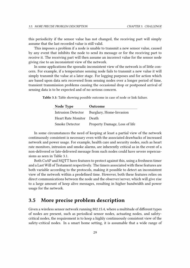
3.5. MORE PRECISE PROBLEM DESCRIPTION CHAPTER 3. CHALLENGE
this periodicity if the sensor value has not changed, the receiving part will simply
assume that the last recorded value is still valid.
This imposes a problem if a node is unable to transmit a new sensor value, caused
by any event that inhibits the node to send its message or for the receiving part to
receive it. The receiving part will then assume an incorrect value for the sensor node
giving rise to an inconsistent view of the network.
In some applications the sporadic inconsistent view of the network is of little con-
cern. For example, if a temperature sensing node fails to transmit a new value it will
simply transmit the value at a later stage. For logging purposes and for action which
are based upon data sets recovered from sensing nodes over a longer period of time,
transient transmission problems causing the occasional drop or postponed arrival of
sensing data is to be expected and of no serious concern.
Table 3.1: Table showing possible outcome in case of node or link failure.
Node Type Outcome
Intrusion Detector Burglary, Home-Invasion
Heart Rate Monitor Death
Smoke Detector Property Damage, Loss of life
In some circumstances the need of keeping at least a partial view of the network
continuously consistent is necessary even with the associated drawbacks of increased
network and power usage. For example, health care and security nodes, such as heart
rate monitors, intrusion and smoke alarms, are inherently critical as in the event of a
non-delivered or late-delivered message from such nodes could have severe repercus-
sions as seen in Table 3.1.
Both CoAP and MQTT have features to protect against this, using a freshness timer
and a Last Will of Testament respectively. The timers associated with these features are
both variable according to the protocols, making it possible to detect an inconsistent
view of the network within a prede�ned time. However, both these features relies on
direct communications between the node and the observer/server, which will give rise
to a large amount of keep alive messages, resulting in higher bandwidth and power
usage for the network.
3.5 More precise problem descriptionGiven a wireless sensor network running 802.15.4, where a multitude of di�erent types
of nodes are present, such as periodical sensor nodes, actuating nodes, and safety-
critical nodes, the requirement is to keep a highly continuously consistent view of the
safety-critical nodes. In a smart home setting, it is assumable that a wide range of
29
3.5. MORE PRECISE PROBLEM DESCRIPTION CHAPTER 3. CHALLENGE
devices will run on 802.15.4 technology in the future, some of which will be safety-
critical. It is therefore desirable to make use of an algorithm that can keep a highly
consistent view of safety-critical devices while other non-safety-critical devices are
present. As such, a common communication set can be shared between all devices
and the speci�c consistency monitor algorithm can be implemented as an application
level algorithm, making use of a shared routing protocol among all nodes. Such an
algorithm will be adaptive as it does not depend on speci�c underlying functionalities
such as MAC, or any speci�c operating system and can be implemented in a wide range
of systems.
The algorithm will be designed as a rudimentary monitoring system, where focus
is to minimize the number of messages required to detect any faulty links or nodes, and
to keep the message size as small as possible, in an e�ort to minimize the total energy
consumption in the network. As faults are expected to happen very seldom, it is not
required by the algorithm itself to identify the source of the fault, rather, if any fault is
detected by the algorithm, further investigative measurements could be launched by
other instances.
Regarding the possibilities of false positives, the algorithm should have the option
to reinitialize the probing of the network an arbitrarily number of times, before re-
porting the possible fault to a higher instance, in order to avoid a high degree of false
positives. The number of times reinitialization is required for a certain false positive
ratio will be speci�c to the actual implementation of the network, as interference and
other in�uencing factors will be highly per installation speci�c.
As the detection time for faults is crucial for safety-critical nodes in order to avoid
the possible outcomes given in Table 3.1, the responsiveness of the algorithm is of high
concern. Ideally, the algorithm should be able to identify a possible fault within a time
frame which is much shorter than what can be provided by the protocols CoAP and
MQTT in their default con�gurations. It should be noted that since the algorithm will
only be designed to detect the presence of faults, not to identify the nature or location
of the fault, more time needs to be allocated in order to identify which node or nodes
are a�ected by the possible fault before appropriate measurements can be taken.
The algorithm will be evaluated given its ability to detect the presence of any faults
in the direct communicative path between any safety-critical node and the sink. With
variable timers as to how often the algorithm should execute the monitoring scheme,
a total number of messages per time unit required can be calculated and a rough esti-
mation of the required energy usage for a certain setup can be given.
As the level of responsiveness that can be acquired by the algorithm correlates with
the energy budget that has been allocated to the algorithm, the thesis will illustrate the
coherence between increased responsiveness and the increase in energy levels required
to maintain a certain level of responsiveness.
As a concluding evaluation, a comparison of results and di�erentiating factors to
30

3.5. MORE PRECISE PROBLEM DESCRIPTION CHAPTER 3. CHALLENGE
the other similar approaches DiMo [13] and Memento [15] for fault detection in safety-
critical networks will be made.
31
4
Methodology
T
here exists a number of di�erent approaches to developing software for wire-
less sensor network devices. This chapter explains the common approach
of using operating system programming to develop software for constrained
devices in the IoT �eld. This approach has become the norm when program-
ming for sensor nodes, as the usage of a base operating system greatly reduces the
need to duplicate functionality and simpli�es the porting of software across di�er-
ent hardware platforms. Moreover, energy-e�ciency when communicating as well as
compatibility between nodes can be increased as the underlying architecture of the
operating system can be shared across di�erent types of nodes.
Also, in e�ort to speed up development and testing, the native approach to pro-
gramming with operating system, which will be used when constructing and testing
the algorithm in the subsequent chapter, is explained in this chapter together with
how virtual topologies can be used for native devices to simulate high-depth networks.
Further, it is explained how network data can be analyzed for both the native port and
hardware nodes using a packet analyzer. To conclude the chapter, a clear presentation
of the di�erent device types that will be used when constructing the algorithm is also
given.
4.1 Operating system programmingThe Operating System Model [45] is a programming model where code is programmed
for a certain operating system kernel, which in turn will compile the code to machine
code for the intended target hardware. Code written for a certain operating system
kernel can be reused and applied to other kinds of hardware which the operating sys-
tem support. In contrary, when writing code for a certain platform, speci�c APIs and
32
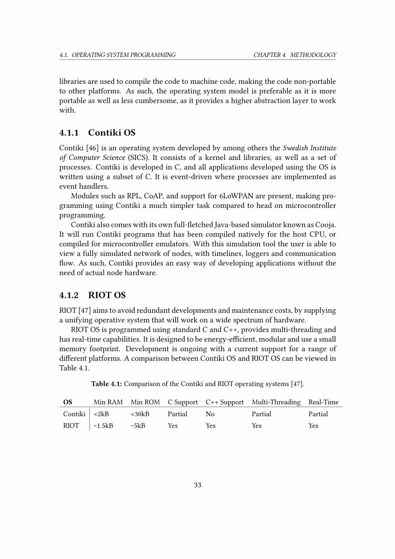
4.1. OPERATING SYSTEM PROGRAMMING CHAPTER 4. METHODOLOGY
libraries are used to compile the code to machine code, making the code non-portable
to other platforms. As such, the operating system model is preferable as it is more
portable as well as less cumbersome, as it provides a higher abstraction layer to work
with.
4.1.1 Contiki OSContiki [46] is an operating system developed by among others the Swedish Instituteof Computer Science (SICS). It consists of a kernel and libraries, as well as a set of
processes. Contiki is developed in C, and all applications developed using the OS is
written using a subset of C. It is event-driven where processes are implemented as
event handlers.
Modules such as RPL, CoAP, and support for 6LoWPAN are present, making pro-
gramming using Contiki a much simpler task compared to head on microcontroller
programming.
Contiki also comes with its own full-�etched Java-based simulator known as Cooja.
It will run Contiki programs that has been compiled natively for the host CPU, or
compiled for microcontroller emulators. With this simulation tool the user is able to
view a fully simulated network of nodes, with timelines, loggers and communication
�ow. As such, Contiki provides an easy way of developing applications without the
need of actual node hardware.
4.1.2 RIOT OSRIOT [47] aims to avoid redundant developments and maintenance costs, by supplying
a unifying operative system that will work on a wide spectrum of hardware.
RIOT OS is programmed using standard C and C++, provides multi-threading and
has real-time capabilities. It is designed to be energy-e�cient, modular and use a small
memory footprint. Development is ongoing with a current support for a range of
di�erent platforms. A comparison between Contiki OS and RIOT OS can be viewed in
Table 4.1.
Table 4.1: Comparison of the Contiki and RIOT operating systems [47].
OS Min RAM Min ROM C Support C++ Support Multi-Threading Real-Time
Contiki <2kB <30kB Partial No Partial Partial
RIOT ~1.5kB ~5kB Yes Yes Yes Yes
33
4.2. NATIVE PROGRAMMING CHAPTER 4. METHODOLOGY
4.2 Native programmingBoth Contiki OS and RIOT OS support native programming [48] [49]. The native plat-
form emulates the hardware needed for nodes and allows the node to run with the
complete software stack of the node OS on a regular UNIX-like desktop, comparable
to that of virtual machine solutions such as Virtualbox and VMware. The bene�ts
of using the native port is that no actual node hardware is needed, as everything is
simulated and run within a regular Linux distribution. As hardware is emulated, the
programmer is not restrained by physical limitations of nodes such as RAM and ROM
size during development. Node communications are allowed to �ow within a con-
trolled environment, without disturbances such as noise. Native programming allows
for fast development and testing as these can both be done using the desktop machine,
compared to programming directly for hardware as this requires the compiled code to
be uploaded to the nodes.
4.3 Virtual topologiesNetwork support for native nodes are given through TAP interfaces. A TAP interface
is a virtual network device that simulates a link layer device. TAP devices are bridged
to allow for inter-device communications.
Tools such as Desvirt[50] can be used to create more complex virtual topologies,
which allows you to specify custom links between nodes and de�ne a loss rate for those
links. As such, topologies with multi-hop communications can be de�ned as visualized
in Figure 4.1.
4.4 Analyzing dataSince the virtual TAP interfaces simulates a real network interface, it is possible to use
packet analyzers such as Wireshark to analyze the network �ow in real time. In order
for Wireshark to be able to parse packets correctly sent over TAP interfaces by RIOT’s
native nodes, a Wireshark dissector is required1.
Analyzing data from real nodes requires a sni�er, which is a node that is able to
forward all packets received to another interface, usually a serial interface such as USB
which would be connected to a desktop computer were the packets can be analyzed
with e.g. Wireshark. Sni�er software are an essential part of analyzing real network
tra�c and software for sni�ers is included within the Operating Systems Contiki and
RIOT. The sni�er could be put anywhere in the network, but it will only be able to
1https://github.com/RIOT-OS/RIOT/tree/master/dist/tools/wireshark_dissector
34
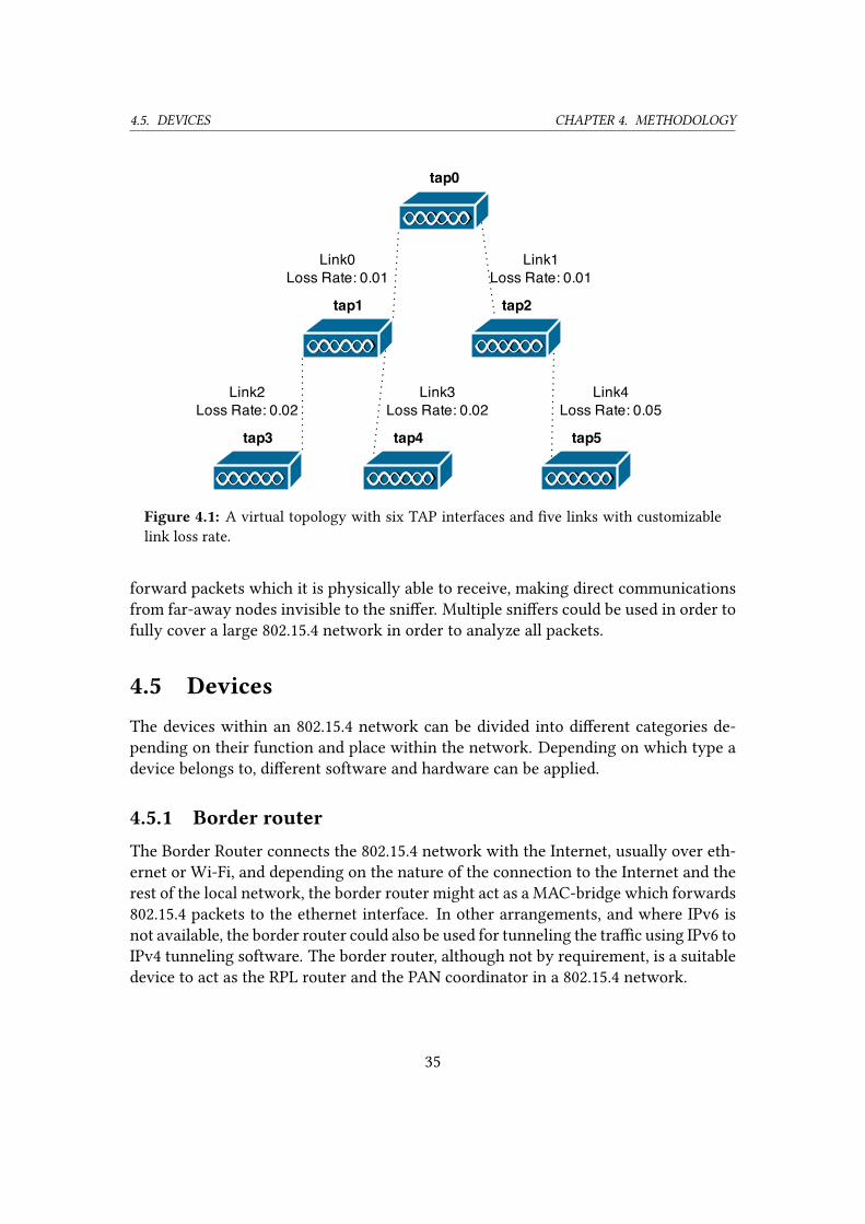
4.5. DEVICES CHAPTER 4. METHODOLOGY
Figure 4.1: A virtual topology with six TAP interfaces and �ve links with customizable
link loss rate.
forward packets which it is physically able to receive, making direct communications
from far-away nodes invisible to the sni�er. Multiple sni�ers could be used in order to
fully cover a large 802.15.4 network in order to analyze all packets.
4.5 DevicesThe devices within an 802.15.4 network can be divided into di�erent categories de-
pending on their function and place within the network. Depending on which type a
device belongs to, di�erent software and hardware can be applied.
4.5.1 Border routerThe Border Router connects the 802.15.4 network with the Internet, usually over eth-
ernet or Wi-Fi, and depending on the nature of the connection to the Internet and the
rest of the local network, the border router might act as a MAC-bridge which forwards
802.15.4 packets to the ethernet interface. In other arrangements, and where IPv6 is
not available, the border router could also be used for tunneling the tra�c using IPv6 to
IPv4 tunneling software. The border router, although not by requirement, is a suitable
device to act as the RPL router and the PAN coordinator in a 802.15.4 network.
35
4.5. DEVICES CHAPTER 4. METHODOLOGY
4.5.2 Local coordinatorLocal coordinators are devices within the wireless sensor network that are capable of
forwarding and relaying frames from other devices in the network. In order for a net-
work to extend spatially, so that all devices are not in direct communicative distance
to the border router, local coordinators are required to relay tra�c. The local coordi-
nators themselves may also act as a functional device, sending sensory data or acting
on received control data. However, due to that a local coordinator is relaying tra�c
from other devices, it will inherently be receiving and transmitting at a higher rate
compared to end devices, and as such will have lower sleep to awake ratio, or in some
cases, be con�gured to never enter sleep mode. This naturally a�ects the power utiliza-
tion of the device, making local coordinators less suitable to be run as battery-powered
devices, compared to end devices.
4.5.3 End deviceThe end device is at the edge of the 802.15.4 network. Only tra�c intended for the end
device is sent to device, as the end device lacks any forwarding capabilities. Depending
on the functionality of the device, the end device can enter sleep mode for extended
periods of time to conserve power. As such, the end devices are well-suited to be
equipped with batteries as their overall power utilization is low or very low, allowing
for the device to be operable using a battery source for a long duration of time.
36
5
Design of the proposed method
A
s mentioned, the only way to make sure that a node is still functioning prop-
erly is for that node to actively communicate on the network. In the ab-
sence of communications from the node, the node will be in an unknown
state from the viewpoint of the border router, as to whether the node is
functional and communicative, or faulty or in any other way unable to communicate.
By using keep-alive messages with associated timers, it is possible to limit the time
in which the node is in this unknown state. Timers could be set arbitrarily and when
such a timer run out, the node could be either assumed non-functional, or further
actions could be taken to verify its current state in the network. As wireless commu-
nications are prone to message loss, it is important to consider that timers might run
out due to delays or interference in the network, which could either be intermittently
present or of a more permanent nature. As for the decision unit, any missed timer
deadline should be treated as a potential malfunction of the node in question, however,
further investigation by the server should be taken to ensure that the node in question
is not available, to avoid a potential false positive. Further investigations could include
an arbitrarily number of rounds of keep-alive tra�c, during which intermittent delays
and interference will have time to recede.
One important aspect is how an increase in message exchange will a�ect the overall
performance of the network, as a smart home WSN might include many di�erent types
of sensor and actuating nodes, which will all share the network with the safety-critical
nodes. Aspects such as the power usage of the nodes, the general throughput and
delays in the network needs to be considered not only for the safety-critical part of the
network, but for the network as a whole.
37
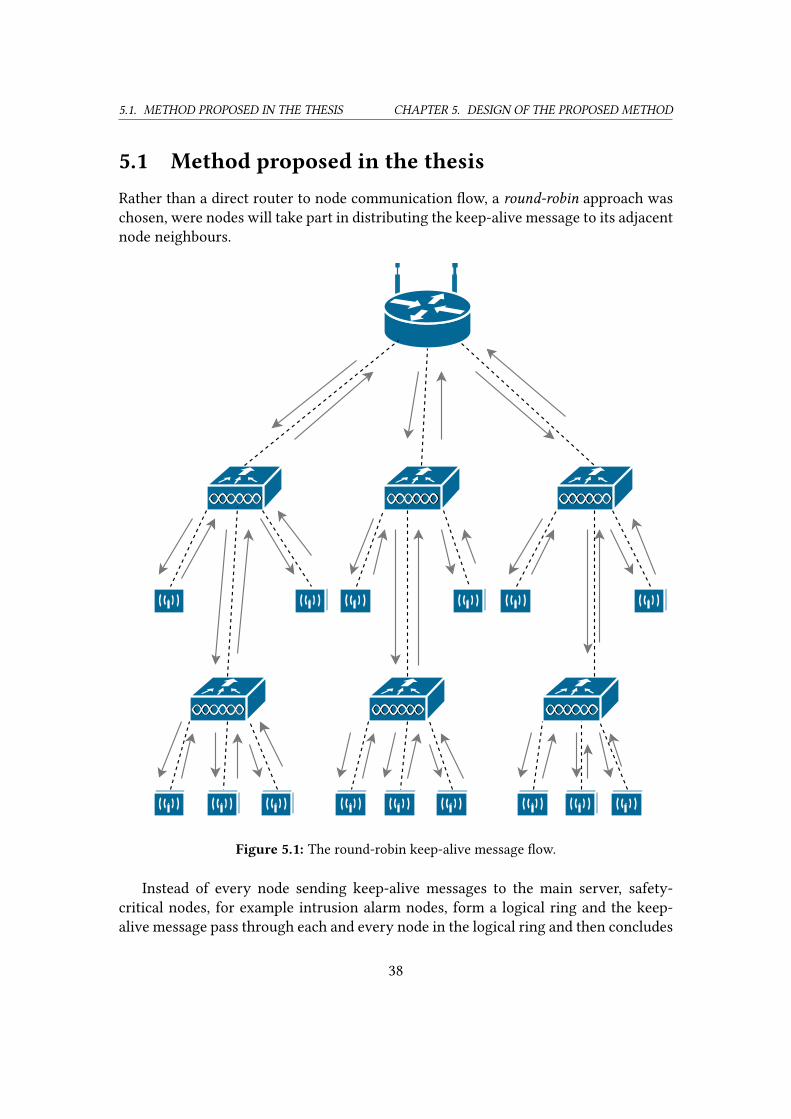
5.1. METHOD PROPOSED IN THE THESIS CHAPTER 5. DESIGN OF THE PROPOSED METHOD
5.1 Method proposed in the thesisRather than a direct router to node communication �ow, a round-robin approach was
chosen, were nodes will take part in distributing the keep-alive message to its adjacent
node neighbours.
Figure 5.1: The round-robin keep-alive message �ow.
Instead of every node sending keep-alive messages to the main server, safety-
critical nodes, for example intrusion alarm nodes, form a logical ring and the keep-
alive message pass through each and every node in the logical ring and then concludes
38
5.1. METHOD PROPOSED IN THE THESIS CHAPTER 5. DESIGN OF THE PROPOSED METHOD
by being sent back to the server. This would severely diminish the amount of messages
required to be sent in a larger wireless sensor network where many local coordinators
and end devices are present at depths greater than one from the border router. For
instance, given the network illustrated in Figure 5.1, a round robin approach would
optimally give rise to a total of 42 messages per keep-alive round. In comparison, if
a direct server to node keep-alive approach was taken, messages would have to pass
through multiple local coordinators multiple times, as every node would be indepen-
dently communicated with.
5.1.1 Time aspectGenerally, this approach will be able to make the decision whether a node is unreach-
able or not within a much smaller time range than the typical timer values of RPL,
MQTT and CoAP. It should act quickly enough so that the possible negative outcomes
given in Table 3.1 could be counteracted given manual or automatic response.
For example, for the critical device types mentioned in Table 3.1 appropriate re-
sponse to node or link failure should be initialized in the matter of seconds, rather
than minutes or even hours which could be the case if relying on the keep-alive or
freshness features of other protocols such as CoAP and MQTT.
Fast response is of high concern especially when it comes to medical devices mon-
itoring vital values, as it has been shown that the survival rate drops incrementally
with time when patients go untreated for life threatening conditions such as cardiac
arrest [51].
The exact time unit for when a decision can be made to whether a fault is present
or not will be highly installation and purpose speci�c, as a number of factors need to
be justi�ed for the speci�c setting.
These factors that needs to be considered when choosing a certain degree of re-
sponsiveness include but are not limited to a) energy-e�ciency, the number of mes-
sages sent per unit of time can be directly linked to the overall energy-consumption of
the system, b) false positives, which are more likely to occur as the wait time before
decision making on fault detection is decreased. Furthermore, c) inherent cost asso-
ciated with the negative outcomes due to node or link failure, for example property
loss or loss of life, needs to be accounted for when deciding on the responsiveness of
the system. Also, d) other applications present on the network needs to be consid-
ered, as rapid keep-alive monitoring may cause latency in other parts of the system,
such as sensor data reporting. Therefore, it is important to evaluate the necessity of
rapid fault detection on a per application basis, as di�erent safety-critical systems may
adhere to di�erent levels of what is considered fast response. For example, health mon-
itoring nodes that are monitoring vital signs may be considered as more pressing and
of higher concern than other safety-critical systems such as smoke detector nodes in
an uninhabited building.
39
5.1. METHOD PROPOSED IN THE THESIS CHAPTER 5. DESIGN OF THE PROPOSED METHOD
5.1.2 Message complexityAs there is no requirement from the algorithm to pinpoint the location of the fault,
i.e. for the server to be able to tell which node or link is responsible for the fault, no
information of participation from nodes needs to be carried in the message itself. This
functionality would however be rendered mute, as the algorithm relies on the absence
of return messages to detect fault, and as such, any information carried in the message
would be unattainable for the server in the case of an undelivered message. As such,
the message length can be kept short, with the only requirement that the message
from each round should be unique, as to avoid stored messages from previous rounds
to intervene with a current keep-alive round, causing a false negative. Since messages
are sent from end node to end node, the total amount of messages required for every
node to announce its continued presence on the network can be reduced to the total
amount of uplinks for the safety-critical sub-topology times two. The safety-critical
sub-topology is de�ned as all safety-critical nodes uplinks as well as the uplinks of any
local coordinator which has any safety-critical node as its descendants.
5.1.3 Algorithm descriptionThe communication exchange presupposes that every end node has a de�ned variable
for its next neighbour, which could either be de�ned as another end node or as the
server. Also, the server has a de�ned variable for the end node that will be the �rst node
to participate in the keep-alive round. The message �ow of the proposed algorithm is
described by the following procedures:
INIT: The server initiates the keep-alive round by creating and storing a nonce. It
will then send a message containing the nonce to the �rst node in the keep-alive
round which has been previously de�ned by the server. The server will at this
point start a timer.
FORWARD: Any node that receives the keep-alive message will relay the message
to its next neighbour which is the node next in line to receive the message. This
will be repeated by every node partipating in the algorithm until the message
reaches the last of the participating nodes in the prede�ned list of nodes. This
node will then relay the message to the server, using the prede�ned variable nextneighbour.
RESET: If and when the server receives the message, it checks the message nonce
with the stored nonce for the round, and if it matches, the server will reset its
timer and then re-initiate the algorithm according to INIT.
If the server fails to receive the message before the timer runs out, or the nonce
received can not be matched with the stored nonce, the round will be considered as
40
5.1. METHOD PROPOSED IN THE THESIS CHAPTER 5. DESIGN OF THE PROPOSED METHOD
failed and one or more of the following actions may be taken a) the algorithm may
be repeated an arbitrarily number of times before one of the other actions are chosen
in order to let potential intermittent interference surpass, this will counteract the pos-
sibility of false positives on account of time; b) an investigating algorithm could be
activated, in order to �nd which node in the keep-alive list did not ful�ll its relay; or
c) the algorithm can choose to report the failed keep-alive to a higher instance, such
as an alarm event.
:
41
6
Results
A
n algorithm as described in Chapter 5 was constructed using the RIOT op-
erating system and tested successfully using the native platform. With the
use of the virtual topology tool Desvirt [50], a virtual network with static
link loss was constructed to accommodate for high-depth network simula-
tion. The results show that a distributed round-robin algorithm is possible to construct
with the RIOT operating system and is operational in a simulated network environ-
ment.
6.1 Simulated network topologyThe simulated topology used for the simulation of the algorithm consisted of the PAN
coordinator, from which the algorithm was initiated, a local coordinator, which relayed
the keep-alive messages to and from the end nodes. Two end nodes included in the
keep-alive algorithm were added to the topology. With this, three links with a statically
con�gured link loss were set up to allow for communications between devices. The
links were con�gured so that the two end nodes would have the local coordinator as
their parent, and any message exchange between the PAN coordinator and the end
nodes would therefore be routed through the local coordinator as visually described
in Figure 6.1.
6.2 Message complexityThe particular topology visualized in Figure 6.1 is one of the most rudimentary topolo-
gies that would still bene�t from a round-robin keep-alive algorithm. Given a regular
ping request/ping response approach by the PAN coordinator, where every node is
42
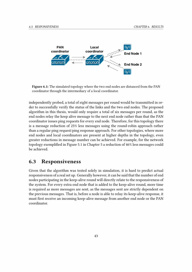
6.3. RESPONSIVENESS CHAPTER 6. RESULTS
Figure 6.1: The simulated topology where the two end nodes are distanced from the PAN
coordinator through the intermediary of a local coordinator.
independently probed, a total of eight messages per round would be transmitted in or-
der to successfully verify the status of the links and the two end nodes. The proposed
algorithm in this thesis, would only require a total of six messages per round, as the
end nodes relay the keep alive message to the next end node rather than that the PAN
coordinator issues ping requests for every end node. Therefore, for this topology there
is a message reduction of 25% less messages using the round-robin approach rather
than a regular ping request/ping response approach. For other topologies, where more
end nodes and local coordinators are present at higher depths in the topology, even
greater reductions in message number can be achieved. For example, for the network
topology exempli�ed in Figure 5.1 in Chapter 5 a reduction of 46% less messages could
be achieved.
6.3 ResponsivenessGiven that the algorithm was tested solely in simulation, it is hard to predict actual
responsiveness of a real set up. Generally however, it can be said that the number of end
nodes participating in the keep-alive round will directly relate to the responsiveness of
the system. For every extra end node that is added to the keep-alive round, more time
is required as more messages are sent, as the messages sent are strictly dependent on
the previous messages. That is, before a node is able to relay its keep-alive response, it
must �rst receive an incoming keep-alive message from another end node or the PAN
coordinator.
43

6.4. ENERGY-EFFICIENCY CHAPTER 6. RESULTS
6.4 Energy-e�ciencyGiven the simulation result, little can be said about the predicted energy consumption
of the algorithm. As energy-e�ciency depends heavily on the MAC-protocol in use,
and as there is currently no method of analyzing energy consumption at runtime for
the RIOT OS1, no results can be obtained on energy consumption given the simulation
setting.
However, crude estimates of energy consumption based on the number of mes-
sages sent can give a rough guideline to actual energy consumption. The authors in
[52] estimates the energy consumption for a number of primitive tasks given a speci-
�ed sensor node platform. Their estimations include a 1.6mJ energy consumption for
packet reception, and a range of 2.1mJ to 3.5mJ for packet transmission. Naturally,
other energy consumption factors are present, such as clear channel assessment and
any associated backo�-periods but these are minuscule in comparison given that the
network is not heavily congested. For the current consumption of the microcontroller,
radio transceiver, and any present sensor hardware, of which are not directly linked to
the receiving, handling, or transmission of proposed algorithm messages, it shall not
be counted towards the energy consumption of the proposed algorithm. This because
if a safety-critical node network were to be set up without the proposed algorithm,
current draw associated with keeping the node operational, such as the energy con-
sumption of the microcontroller, would still be present. Given that that the algorithm
is purely event-based, that is, the algorithm is not invoked by the end nodes unless a
keep-alive message is received and no timers that are associated with the algorithm
are present at the end nodes, it can be assumed the algorithm itself will not provoke
any passive energy consumption by the end node.
As such, using the energy estimations given by [52] it can be deducted that the
participation by a node in the algorithm would infer a estimated energy consumption
of 3.7mJ to 5.1mJ for receiving and relaying the keep-alive message for one individual
node. The rate of which a node receives keep-alive message is directly proportional
to the total energy consumption of the algorithm, due to the cascading procedure of
the algorithm. Since the responsiveness of the algorithm can be deduced to the timers
associated with the algorithm, i.e. the time-frame before a keep-alive round is deemed
as failed and the wait-time for re-initiating the algorithm, the total energy consumption
of the algorithm can be directly linked to the rate of which messages are sent and
consequently the responsiveness of the algorithm.
1https://github.com/RIOT-OS/RIOT/wiki/SWP14 [accessed 2015-06-12]
44
6.5. FALSE POSITIVES CHAPTER 6. RESULTS
6.5 False positivesThe rate of false positives can be calculated given the number of messages per round
and the static link loss per link as visualized in Figure 6.2. It shows that given the
criteria that the algorithm would be operating in a home environment with a range
of 10 to 100 safety-critical nodes present, the rate of false positives quickly becomes
intolerable as more links are introduced in the network with the given static link loss
of 0.01, 0.02, and 0.05. To combat this, multiple rounds can be executed before a failure
is allowed to be acted on, as to limit the number of false positives. Figure 6.3 shows the
failure rate when three consecutive rounds are executed, given that all three rounds
fail to complete. This shows that the algorithm is vulnerable to scaling, as it only
takes one link failure for the whole round to fail. Another angle of attack to minimize
the amount of false positives is by using subgroups, where the algorithm would run
independently for a limited subset of the total amount of safety-critical nodes. In such
case, the rate of failure could be reduced, at the total cost of a few extra messages.
45
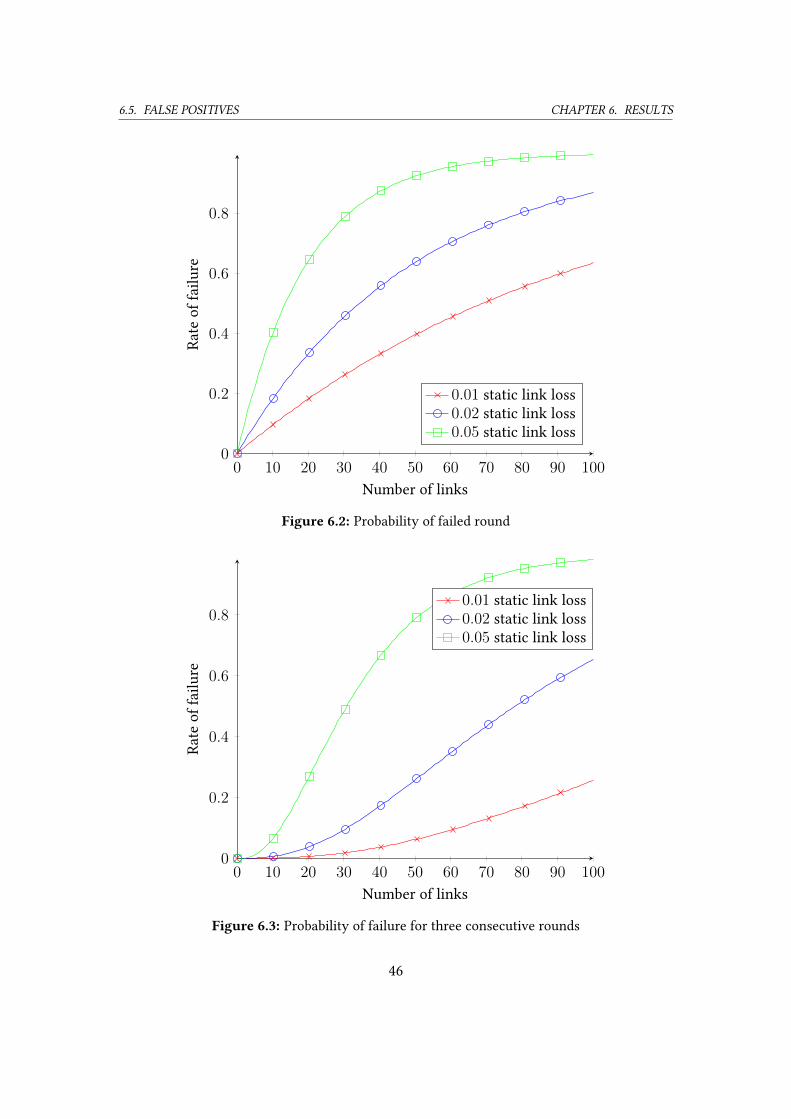
6.5. FALSE POSITIVES CHAPTER 6. RESULTS
0 10 20 30 40 50 60 70 80 90 1000
0.2
0.4
0.6
0.8
Number of links
Rate
of
failu
re
0.01 static link loss
0.02 static link loss
0.05 static link loss
Figure 6.2: Probability of failed round
0 10 20 30 40 50 60 70 80 90 1000
0.2
0.4
0.6
0.8
Number of links
Rate
of
failu
re
0.01 static link loss
0.02 static link loss
0.05 static link loss
Figure 6.3: Probability of failure for three consecutive rounds
46
7
Discussion
F
ew conclusions can be drawn from the results of the simulation as to how
the algorithm would perform in a real network environment. Other than con-
�rming the functionality and proper implementation of the algorithm, a real
network setup or a more advanced simulation is required in order to analyze
the algorithm in a dynamical environment. As such, there is a number of concerns that
could not be addressed due to the nature of running simulated nodes in a simulated
network environment.
Moreover, authentication was left out in the algorithm that was implemented. As
authenticity is of high concern in order to verify the correctness of received keep-
alive messages, it is of high importance that either the algorithm itself can provide the
necessary authentication, or that underlying layers are able to provide it.
7.1 Energy consumptionLow energy consumption is of major concern for wireless sensor networks. Generally,
this is achieved by allowing battery-powered devices to enter sleep mode and imple-
menting features such as duty cycles and message bu�ering. In accordance to this,
any extra information that needs to be sent or received by battery-powered nodes,
will a�ect power utilization negatively.
As such, the keep-alive algorithm proposed in Chapter 5, will severely a�ect the
power consumption of the network, even though e�orts has been taken to limit the
total amount of messages required to complete one round of algorithm.
There are a number of approaches to further limit the power usage. Arguable, the
most e�ective method to decrease the energy utilization required by the algorithm is
to limit the number of devices that are regarded as safety-critical devices and therefore
47
7.2. AUTHENTICATION CHAPTER 7. DISCUSSION
not being a part of the round-robin algorithm.
One important aspect to consider is that not only will the safety-critical devices
that are part of the round-robin algorithm su�er from higher power utilization, but
also any other nodes that are within communication distance of any of the critical de-
vices within the keep-alive algorithm, as CSMA/CA will force nodes to �rst perform a
clear channel assessment (CCA) by listening for activity on the channel and if present,
postpone their transmission. For beacon-enabled networks however, this can be cir-
cumvented by using Guaranteed Time Slots (GTS). Another approach to minimize wait
time and collisions, and in extension energy consumption is a multi-channel approach,
made possible by either equipping devices with multiple hardware transsceivers, or to
make use of a scheduling algorithm in order to synchronize channel change between
nodes [53] [54] [55]. For deployment, the choice of MAC protocol is paramount, as
it is one of the most in�uential factor for energy-consumption and latency when im-
plementing an algorithm such as the one proposed. There exists a wide number of
MAC-protocols [56] and many elements needs to be considered as to how the over-
all performance of the network will come to be, including power utilization for non-
safety-critical nodes present in the network.
7.2 AuthenticationAuthentication is an important step in order to con�rm that the nodes are in fact oper-
ational and communicative. Without authentication the network becomes vulnerable
to man-in-the-middle attacks. Link-level authentication can authenticate links, but this
requires trust from all devices in the message path. Therefore, without top-level au-
thentication every device that relay keep-alive messages, i.e. the local coordinators, are
required to be trusted devices. If end-to-end authentication is used, there’s no need to
trust intermediate devices and given the authentication, this will guarantee that every
intended node took part in the keep-alive round.
7.3 Multi DODAG for safety-critical devicesAs explained in subsection 2.3.2, multiple DODAGs can be created with RPL, giving
the option to choose between multiple routing strategies. Therefore, it would be pos-
sible to create an instance of RPL strictly for safety-critical devices, allowing timers
to be set according to the need of the safety-critical devices, while routing for other
non-safety-critical devices could be maintained by another instance of RPL. By de�n-
ing the parameter maximum interval size of the trickle algorithm to a low time unit in
accordance to the need of safety-critical devices, RPL could be set up to mimic much
of the functionality of the proposed algorithm. RPL is however not designed with a
48
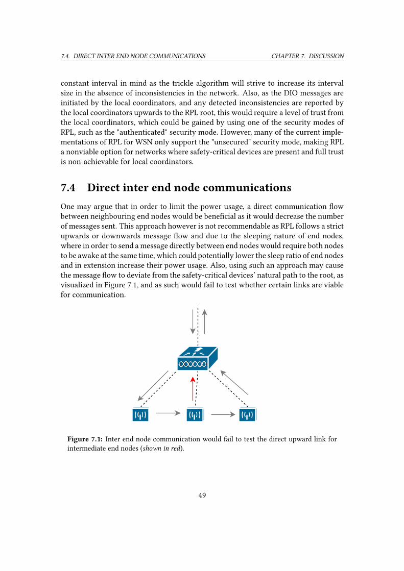
7.4. DIRECT INTER END NODE COMMUNICATIONS CHAPTER 7. DISCUSSION
constant interval in mind as the trickle algorithm will strive to increase its interval
size in the absence of inconsistencies in the network. Also, as the DIO messages are
initiated by the local coordinators, and any detected inconsistencies are reported by
the local coordinators upwards to the RPL root, this would require a level of trust from
the local coordinators, which could be gained by using one of the security modes of
RPL, such as the "authenticated" security mode. However, many of the current imple-
mentations of RPL for WSN only support the "unsecured" security mode, making RPL
a nonviable option for networks where safety-critical devices are present and full trust
is non-achievable for local coordinators.
7.4 Direct inter end node communicationsOne may argue that in order to limit the power usage, a direct communication �ow
between neighbouring end nodes would be bene�cial as it would decrease the number
of messages sent. This approach however is not recommendable as RPL follows a strict
upwards or downwards message �ow and due to the sleeping nature of end nodes,
where in order to send a message directly between end nodes would require both nodes
to be awake at the same time, which could potentially lower the sleep ratio of end nodes
and in extension increase their power usage. Also, using such an approach may cause
the message �ow to deviate from the safety-critical devices’ natural path to the root, as
visualized in Figure 7.1, and as such would fail to test whether certain links are viable
for communication.
Figure 7.1: Inter end node communication would fail to test the direct upward link for
intermediate end nodes (shown in red).
49
7.5. RELATED WORKS CHAPTER 7. DISCUSSION
7.5 Related worksIn comparison to other methods of fault detection in WSN, like DiMo [13] proposed
by Meier, the approach chosen in this thesis is not a stand-alone implementation, as it
relies on the routing protocol RPL for routing. DiMo is able to provide monitoring for
safety-critical nodes at competitive energy consumption and low false-positive rate,
however the maximum tolerable delay of reporting errors is set at �ve minutes. In the
given con�guration, with the addition of the alarm reporting protocol Dwarf, Meier
concludes that the network lifetime would exceed operational time of three years. In
Memento [15], with its similar approach with periodic heartbeats, the authors advo-
cates the reuse of other protocols messages, such as periodic routing advertisements
or sensor samples to be used for failure detection. Unfortunately, the choice of aggre-
gating messages as to not increase the message load close to the sink, has the inad-
vertent e�ect of increasing the latency of the system. For the approach in this thesis,
which is fundamentally di�erent from the DiMO and Memento approach, as it relies
on a round-robin approach, has the given advantage of being light-weight in com-
parison, as nodes are only instructed to forward a message to a neighbour, rather than
monitor neighbours heartbeat messages. The main disadvantage with this round-robin
approach however, has to do with scaling, as every node added to the algorithm will
cause the round-robin ring to enlarge and as such, more time is needed to complete
the round-robin sequence. As the algorithm was designed with smart homes in mind,
the number of safety-critical nodes in a network may be limited to a small number of
nodes, for which a tolerable latency can be achieved. However, if a large number of
nodes participates in the round-robin sequence, the latency of the system may cause
the overall responsiveness to fall outside of acceptable levels.
7.6 Open issues and future worksAs the network topology simulation tool Desvirt only supports static link loss, it fails
to su�ciently simulate a real wireless network topology where dynamical link loss is
present. As such, only a speculative evaluation of how the algorithm would perform
in a real environment can be made. The simulation tools used in the work, the native
platform for RIOT OS and the network topology tool Desvirt have no mechanism for
simulating power consumption, and as such no conclusions can be drawn whether the
algorithm is a viable option for battery-powered nodes or if the power usage is simply
too excessive for battery-powered units.
One major issue for the algorithm proposed by the thesis is the long convergence
time in the onset of a global repair by the RPL protocol. As the algorithm relies on RPL
for routing, the algorithm itself is very simplistic and carries a small code footprint, but
as such, it relies on RPL for routing and the timers associated with RPL are in�uential
50

7.6. OPEN ISSUES AND FUTURE WORKS CHAPTER 7. DISCUSSION
to the responsiveness of the proposed algorithm. This means that when RPL is called to
perform local and global repairs more frequently, such as when safety-critical nodes are
non-stationary, the responsiveness of the proposed algorithm may be heavily a�ected.
This might however be combated by using a separate RPL DODAG for safety-critical
nodes where the RPL associated timers has been adjusted accordingly.
Therefore, the author proposes that the algorithm should be tested in a real en-
vironment where dynamical interference is present and with a range of typical WSN
hardware, in order to evaluate if the algorithm is feasible for implementation in areas
where WSN are present, such as Smart Home environments. With a real environment
set up, hard numbers can be gathered on how well the algorithm performs under a
certain hardware set up. Interesting �gures, for instance latency, energy consumption
and the rate of false positives, could then be compared to other keep alive algorithms
for wireless sensor networks, such as the heart beat algorithms[13][15].
51
8
Conclusions
T
his thesis has presented the issue of keeping a continuously consistent view
within Wireless Sensor Networks while still trying to adhere to the mini-
malist and low energy principles of WSN. The thesis proposes an algorithm
that make use of a round-robin approach where end nodes are relaying a
keep-alive message to other end nodes, in order to minimize the number of messages
required to keep a continuously consistent view of safety-critical nodes and links.
As for wireless communications, it is not currently possible reach the same relia-
bility and response level as a closed circuit system, but wireless sensor networks have
the advantage of being both cheaper and easier to install compared to a closed circuit
system. As such, an approach where safety-critical devices are managed in a wireless
sensor network rather than a closed circuit system may be realizable in homes or other
areas where cost is of a major concern. The comparative cost of such an installation
compared to that of a closed circuit system might be that modest that a wireless sen-
sor network approach to security should rather be compared to a non-security premise
than a closed circuit system as a wireless security approach can o�er some security at
a comparably small investment.
Issues exists, such as �nding a suitable algorithm to �ne-tune the variables used by
the proposed algorithm, in order to reach a fast-response system where the number of
false positives are kept low.
52

Bibliography
[1] M. R. Alam, M. B. I. Reaz, M. A. M. Ali, A Review of Smart Homes—Past,
Present, and Future, IEEE Transactions on Systems, Man, and Cybernetics, Part
C (Applications and Reviews) 42 (6) (2012) 1190–1203.
URL http://ieeexplore.ieee.org/lpdocs/epic03/wrapper.htm?arnumber=6177682
[2] L. Lamport, R. Shostak, M. Pease, The Byzantine Generals Problem, ACM Trans.
Program. Lang. Syst. 4 (3) (1982) 382–401.
URL http://doi.acm.org/10.1145/357172.357176
[3] J. Ko, J. Eriksson, N. Tsiftes, S. Dawson-haggerty, A. Terzis, A. Dunkels, D. Culler,
ContikiRPL and TinyRPL: Happy Together, in: In Proceedings of the workshop
on Extending the Internet to Low power and Lossy Networks (IP+SN 2011, 2011.
[4] J. Ko, J. Eriksson, N. Tsiftes, S. Dawson-haggerty, M. Durvy, A. Terzis, A. Dunkels,
D. Culler, Beyond Interoperability: Pushing the Performance of Sensornet IP
Stacks, in: In Proceedings of the International Conference on Embedded Net-
worked Sensor Systems (ACM SenSys, 2011.
[5] I. Ishaq, D. Carels, G. K. Teklemariam, J. Hoebeke, F. Van den Abeele,
E. De Poorter, I. Moerman, P. Demeester, IETF standardization in the �eld of the
Internet of Things (IoT): a survey, JOURNAL OF SENSOR AND ACTUATOR NET-
WORKS (2) (2013) 235–287.
URL http://dx.doi.org/10.3390/jsan2020235
[6] F. Araújo, L. Rodrigues, On the Monitoring Period for Fault-Tolerant Sensor Net-
works, in: C. Maziero, J. Gabriel Silva, A. Andrade, F. de Assis Silva (Eds.), De-
pendable Computing, Vol. 3747 of Lecture Notes in Computer Science, Springer
Berlin Heidelberg, 2005, pp. 174–190.
URL http://dx.doi.org/10.1007/11572329_15
53
BIBLIOGRAPHY BIBLIOGRAPHY
[7] H. Liu, A. Nayak, I. Stojmenović, Fault-Tolerant Algorithms/Protocols in Wireless
Sensor Networks, in: S. C. Misra, I. Woungang, S. Misra (Eds.), Guide to Wireless
Sensor Networks, Computer Communications and Networks, Springer London,
2009, pp. 261–291.
URL http://dx.doi.org/10.1007/978-1-84882-218-4_10
[8] G. Călinescu, I. Măndoiu, A. Zelikovsky, Symmetric Connectivity with Minimum
Power Consumption in Radio Networks, in: R. Baeza-Yates, U. Montanari, N. San-
toro (Eds.), Foundations of Information Technology in the Era of Network and
Mobile Computing, Vol. 96 of IFIP — The International Federation for Informa-
tion Processing, Springer US, 2002, pp. 119–130.
URL http://dx.doi.org/10.1007/978-0-387-35608-2_11
[9] S. Chessa, P. Santi, Crash Faults Identi�cation in Wireless Sensor Networks, Com-
put. Commun. 25 (14) (2002) 1273–1282.
URL http://dx.doi.org/10.1016/S0140-3664(02)00030-0
[10] S. B. Attia, A. Cunha, A. Koubâa, M. Alves, Fault-tolerance mechanisms for Zig-
Bee wireless sensor networks, 2007.
[11] R. Alena, R. Gilstrap, J. Baldwin, T. Stone, P. Wilson, Fault tolerance in ZigBee
wireless sensor networks, in: Aerospace Conference, 2011 IEEE, 2011, pp. 1–15.
[12] K. Sha, W. Shi, On the e�ects of consistency in data operations in wireless sensor
networks, in: Parallel and Distributed Systems, 2006. ICPADS 2006. 12th Interna-
tional Conference on, Vol. 1, 2006, pp. 8 pp.–.
[13] A. Meier, Safety-Critical Wireless Sensor Networks, Ph.D. thesis, SWISS FED-
ERAL INSTITUTE OF TECHNOLOGY ZURICH (2009).
[14] S.-C. Wang, S.-Y. Kuo, Communication strategies for heartbeat-style failure de-
tectors in wireless ad hoc networks, in: Dependable Systems and Networks, 2003.
Proceedings. 2003 International Conference on, 2003, pp. 361–370.
[15] S. Rost, H. Balakrishnan, Memento: A Health Monitoring System for Wireless
Sensor Networks, in: Sensor and Ad Hoc Communications and Networks, 2006.
SECON ’06. 2006 3rd Annual IEEE Communications Society on, Vol. 2, 2006, pp.
575–584.
[16] T. S. Rappaport, Y. Zhuang, J. Cappos, R. McGeer, Future Internet Bandwidth
Trends: An Investigation on Current and Future Disruptive Technologies (2014).
[17] D. Evans, The internet of things: How the next evolution of the internet is chang-
ing everything, CISCO white paper 1.
54
BIBLIOGRAPHY BIBLIOGRAPHY
[18] Gartner, Gartner Says 4.9 Billion Connected "Things" Will Be in Use in 2015, 2014.
URL http://www.gartner.com/newsroom/id/2905717
[19] L. Smith, I. Lipner, Free pool of ipv4 address space depleted, Number Resource
Organization. Retrieved 3.
[20] Wikipedia, List of wireless sensor nodes — Wikipedia, The Free Encyclopedia,
[Online; accessed 8-March-2015] (2015).
URL http://en.wikipedia.org/w/index.php?title=List_of_wireless_sensor_nodes
[21] C. Wang, K. Sohraby, B. Li, M. Daneshmand, Y. Hu, A survey of transport proto-
cols for wireless sensor networks, IEEE network 20 (3) (2006) 34–40.
[22] IEEE Standard for Local and metropolitan area networks–Part 15.4: Low-Rate
Wireless Personal Area Networks (LR-WPANs), IEEE Std 802.15.4-2011 (Revision
of IEEE Std 802.15.4-2006) (2011) 1–314.
[23] A. J. Odey, D. Li, Low Power Transceiver Design Parameters for Wireless Sensor
Networks.
URL http://dx.doi.org/10.4236/wsn.2012.410035
[24] E. H. Callaway, Wireless Sensor Networks: Architectures and Protocols, CRC
Press, Inc., Boca Raton, FL, USA, 2003.
[25] I. Stojmenovic, Handbook of Sensor Networks: Algorithms and Architectures,
Wiley Series on Parallel and Distributed Computing, Wiley, 2005.
[26] E. Nataf, O. Festor, Online Estimation of Battery Lifetime for Wireless Sensors
Network, ArXiv e-prints.
[27] S. Deering, R. Hinden, Internet Protocol, Version 6 (IPv6) Speci�cation, RFC 2460
(Draft Standard), updated by RFCs 5095, 5722, 5871, 6437, 6564, 6935, 6946, 7045,
7112 (Dec. 1998).
URL http://www.ietf.org/rfc/rfc2460.txt
[28] J. Hui, P. Thubert, Compression Format for IPv6 Datagrams over IEEE 802.15.4-
Based Networks, RFC 6282 (Proposed Standard) (Sep. 2011).
URL http://www.ietf.org/rfc/rfc6282.txt
[29] G. Montenegro, N. Kushalnagar, J. Hui, D. Culler, Transmission of IPv6 Packets
over IEEE 802.15.4 Networks, RFC 4944 (Proposed Standard), updated by RFCs
6282, 6775 (Sep. 2007).
URL http://www.ietf.org/rfc/rfc4944.txt
55
BIBLIOGRAPHY BIBLIOGRAPHY
[30] M. Dohler, T. Watteyne, T. Winter, D. Barthel, Routing Requirements for Urban
Low-Power and Lossy Networks, RFC 5548 (Informational) (May 2009).
URL http://www.ietf.org/rfc/rfc5548.txt
[31] J. Martocci, P. D. Mil, N. Riou, W. Vermeylen, Building Automation Routing Re-
quirements in Low-Power and Lossy Networks, RFC 5867 (Informational) (Jun.
2010).
URL http://www.ietf.org/rfc/rfc5867.txt
[32] K. Pister, P. Thubert, S. Dwars, T. Phinney, Industrial Routing Requirements in
Low-Power and Lossy Networks, RFC 5673 (Informational) (Oct. 2009).
URL http://www.ietf.org/rfc/rfc5673.txt
[33] A. Brandt, J. Buron, G. Porcu, Home Automation Routing Requirements in Low-
Power and Lossy Networks, RFC 5826 (Informational) (Apr. 2010).
URL http://www.ietf.org/rfc/rfc5826.txt
[34] T. Winter, P. Thubert, A. Brandt, J. Hui, R. Kelsey, P. Levis, K. Pister, R. Struik,
J. Vasseur, R. Alexander, RPL: IPv6 Routing Protocol for Low-Power and Lossy
Networks, RFC 6550 (Proposed Standard) (Mar. 2012).
URL http://www.ietf.org/rfc/rfc6550.txt
[35] J. Vasseur, M. Kim, K. Pister, N. Dejean, D. Barthel, Routing Metrics Used for Path
Calculation in Low-Power and Lossy Networks, RFC 6551 (Proposed Standard)
(Mar. 2012).
URL http://www.ietf.org/rfc/rfc6551.txt
[36] P. Levis, T. Clausen, J. Hui, O. Gnawali, J. Ko, The Trickle Algorithm, RFC 6206
(Proposed Standard) (Mar. 2011).
URL http://www.ietf.org/rfc/rfc6206.txt
[37] J. Postel, Transmission Control Protocol, RFC 793 (INTERNET STANDARD), up-
dated by RFCs 1122, 3168, 6093, 6528 (Sep. 1981).
URL http://www.ietf.org/rfc/rfc793.txt
[38] J. Postel, User Datagram Protocol, RFC 768 (INTERNET STANDARD) (Aug. 1980).
URL http://www.ietf.org/rfc/rfc768.txt
[39] D. Thangavel, X. Ma, A. Valera, H.-X. Tan, C.-Y. Tan, Performance evaluation
of MQTT and CoAP via a common middleware, in: Intelligent Sensors, Sensor
Networks and Information Processing (ISSNIP), 2014 IEEE Ninth International
Conference on, 2014, pp. 1–6.
56
BIBLIOGRAPHY BIBLIOGRAPHY
[40] Z. Shelby, K. Hartke, C. Bormann, The Constrained Application Protocol (CoAP),
RFC 7252 (Proposed Standard) (Jun. 2014).
URL http://www.ietf.org/rfc/rfc7252.txt
[41] E. Rescorla, N. Modadugu, Datagram Transport Layer Security Version 1.2, RFC
6347 (Proposed Standard) (Jan. 2012).
URL http://www.ietf.org/rfc/rfc6347.txt
[42] S. Jucker, Securing the Constrained Application Protocol, Master’s thesis, ETH
Zurich (2012).
[43] IBM/OASIS, MQTT Version 3.1.1, [Online; accessed 2-November-2014] (2014).
URL http://docs.oasis-open.org/mqtt/mqtt/v3.1.1/mqtt-v3.1.1.html
[44] A. Stanford-Clark, H. Truong, MQTT for sensor networks (MQTT-S) protocol
speci�cation (2013).
URL http://mqtt.org/new/wp-content/uploads/2009/06/MQTT-SN_spec_v1.2.pdf
[45] M. O. Farooq, T. Kunz, Operating systems for wireless sensor networks: A survey,
Sensors 11 (6) (2011) 5900–5930.
[46] A. Dunkels, B. Gronvall, T. Voigt, Contiki - A Lightweight and Flexible Operating
System for Tiny Networked Sensors, in: Proceedings of the 29th Annual IEEE
International Conference on Local Computer Networks, LCN ’04, IEEE Computer
Society, Washington, DC, USA, 2004, pp. 455–462.
URL http://dx.doi.org/10.1109/LCN.2004.38
[47] E. Baccelli, O. Hahm, M. Günes, RIOT OS: Towards an OS for the Internet of
Things, INFOCOM’2013 (2013) 2453–2454.
URL http://hal.inria.fr/hal-00945122/
[48] F. Österlind, A sensor network simulator for the Contiki OS, SICS Research Re-
port.
[49] O. Hahm, E. Baccelli, H. Petersen, M. Wählisch, T. Schmidt, Simply RIOT: Teach-
ing and Experimental Research in the Internet of Things, in: 13th ACM/IEEE
International Conference on Information Processing in Sensor Networks (IPSN
2014), ACM, Berlin, Germany, 2014.
URL https://hal.inria.fr/hal-01058634
[50] DES-Testbed, desvirt, https://github.com/des-testbed/desvirt (2015).
57
BIBLIOGRAPHY
[51] S. IG, W. GA, F. I. BJ, et al, Improved out-of-hospital cardiac arrest survival
through the inexpensive optimization of an existing de�brillation program: Opals
study phase ii, JAMA 281 (13) (1999) 1175–1181.
URL +http://dx.doi.org/10.1001/jama.281.13.1175
[52] K. Jalsan, K. Flouri, G. Feltrin, Energy Consumption Estimation for Wireless Sen-
sor Network Layout Optimization, in: Ubi-Media Computing and Workshops
(UMEDIA), 2014 7th International Conference on, 2014, pp. 238–242.
[53] E. Toscano, L. Lo Bello, Multichannel Superframe Scheduling for IEEE 802.15.4
Industrial Wireless Sensor Networks, IEEE Transactions on Industrial Informat-
ics 8 (2012) 337–350.
URL http://ieeexplore.ieee.org/xpl/articleDetails.jsp?arnumber=6009195
[54] N. Abdeddaim, F. Theoleyre, F. Rousseau, A. Duda, Multi-Channel Cluster Tree
for 802.15.4 Wireless Sensor Networks, IEEE, 2012, pp. 590–595.
[55] S. Chantaraskul, Multi-channel Utilization Algorithms for IEEE 802.15. 4 based
Wireless Network: A Survey, Engineering Journal 17 (3) (2013) 119–126.
[56] P. Suriyachai, U. Roedig, A. Scott, A Survey of MAC Protocols for Mission-Critical
Applications in Wireless Sensor Networks, Communications Surveys Tutorials,
IEEE 14 (2) (2012) 240–264.
58