Embed Size (px)
Citation preview

Mastercam 2017 Airplane Fuselage SW 16 to MCam 17 Page 17-1
Airplane
SOLIDWORKS 16 to Mastercam 20172016
A. Open File in Mastercam 2017.Step 1. If necessary, save your Fuselage file in SOLIDWORKS.
Step 2. In Mastercam 2017, click Open (Ctrl-O) onthe Quick Access Toolbar QAT.
Step 3. In the Open dialog box set Files of type to SOLIDWORKS Files, select your FUSELAGE file and click Open, Fig. 1.
Step 4. Change to the Isometric View. Right click in the graphics win-dow and click (Alt-7).
B. Confirm Units are Inches.
Step 1. Confirm in the bottom right corner of the display units are Inches, Fig. 2.
C. Save Your File.Step 1. Click Save As
(Ctrl-Shift-S) on the Quick Access Toolbar QAT.
Step 2. Key-in FUSE-LAGE for the filename and press ENTER.
Chapter 3
10/30/16
Chapter 3Mastercam 2017Chapter 17
Fig. 1
Fig. 2
© Cudacountry.net Tech Edhttp://www.cudacountry.net email:[email protected]

Mastercam 2017 Airplane Fuselage SW 16 to MCam 17 Page 17-2
D. Move to Origin.Step 1. Display the origin. Use F9 to toggle axes, Fig. 3.
Step 2. On the Transform tab click Move to Origin .
Step 3. Press the C key on keyboard to configure Auto Cursor behavior of your cursor to snap to Arc Center.
Step 4. Click front arc of Motor hole as point to translate from, Fig. 3. Be sure to select arc of hole.
Step 5. Right click the graphics window and click Clear Colors .
Step 6. Confirm Origin is at center of Motor hole, Fig. 4.
Step 7. Save (Ctrl-S).
Fig. 3 Fig. 4
SOLIDWORKS Origin
Motor hole arc New
Mastercam Origin

Mastercam 2017 Airplane Fuselage SW 16 to MCam 17 Page 17-3
E. Create WCS BOTTOM CUT Plane.Step 1. Display the Planes Manger (Alt-L).
Step 2. In the Planes Manger: Click Create a new plane drop down and select Relative to WCS > Top, Fig. 5.
Step 3. In the New Plane dialog box: Key-in BOTTOM CUT for name, Fig. 6 Origin X 0 Origin Y -1.25 Origin Z 0 Uncheck Set WCS Click OK . Note position of X, Y and Z, Fig. 7.
Step 4. Back in the Planes Manager: Right click BOTTOM CUT plane and select Rotate incremental, Fig. 8.
Step 5. In the Rotate Incremental dialog box set: About X 90, Fig. 9 About Z -90 Confirm position of X, Y and Z, Fig. 10. Click OK .
Tip: In the Fuselage WCSs we want the X postive axes running from Origin to rear of Fuselage. Z axis running out away from Origin (up if you switch to Iso view, Fig. 10.
Fig. 6
Fig. 9
Fig. 5
Fig. 7
Fig. 8
Fig. 10

Mastercam 2017 Airplane Fuselage SW 16 to MCam 17 Page 17-4
F. Create WCS TOP CUT Plane.Step 1. In the Planes Manger:
Click Create a new plane drop down and select Relative to WCS > Top, Fig. 11.
Step 2. In the New Plane dialog box: Key-in TOP CUT for name, Fig. 12 Origin X 0 Origin Y 1.25 Origin Z 0 Click OK .Note position of X, Y and Z, Fig. 13.
Step 3. Back in the Planes Manager: Right click TOP CUT plane and select Rotate incremental, Fig. 14.
Step 4. In the Rotate Incremental dialog box set: About X -90, Fig. 15 About Y 0 About Z 90 Confirm position of X, Y and Z, Fig. 16. Click OK .
Step 5. Back in Planes Manager: Click Set All , Fig. 17.
Step 6. Change to the Isometric View. Right click in the graphics window and click (Alt-7).
Step 7. Save (Ctrl-S).
Fig. 12
Fig. 15
Fig. 13
Fig. 16
Fig. 11
Fig. 14
Fig. 17
Mastercam 2017 Airplane Fuselage SW 16 to MCam 17 Page 17-5
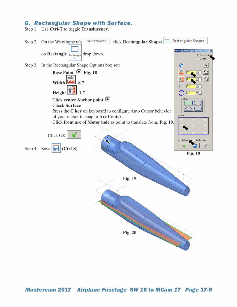
G. Rectangular Shape with Surface.Step 1. Use Ctrl-T to toggle Translucency.
Step 2. On the Wireframe tab , click Rectangular Shapes
on Rectangle drop down.
Step 3. In the Rectangular Shape Options box set: Base Point Fig. 18
Width 8.7
Height 1.7 Click center Anchor point Check Surface Press the C key on keyboard to configure Auto Cursor behavior of your cursor to snap to Arc Center. Click front arc of Motor hole as point to translate from, Fig. 19.
Click OK .
Step 4. Save (Ctrl-S).Fig. 18
Fig. 19
Fig. 20

Mastercam 2017 Airplane Fuselage SW 16 to MCam 17 Page 17-6
H. Translate Move Surface.Step 1. Use Ctrl-T to toggle off Translucency.
Step 2. On the Transform tab click Translate .
Step 3. Click the surface to select it and click End Selection (ENTER), Fig. 21.
Step 4. In Translate dialog box set: Select Move Fig. 22 -.125 Click Apply .
I. Translate Copy Surface.Step 1. Click the surface to select it and click End Selection
(ENTER), Fig. 23.
Step 2. In Translate dialog box set: Select Copy Fig. 24 .25 Click OK .
Step 3. Right click the graphicswindow and click ClearColors .
Step 4. Save (Ctrl-S).
Fig. 22
Fig. 21
Fig. 24
Fig. 23
Fig. 25