Embed Size (px)
Citation preview

MASTER THESIS
Title:Simulation of
Clamping device
Present By: directed by:
Azzeddine Saadi Dr Attila Szilágyi
UNIVERSITY OF MISKOLC
FACULTY OF MECHANICAL ENGINEERING AND INFORMATICS
DEPARTMENT OF MACHINE TOOLS
June 2016

ACKNOWLEDGEMENTS
I would like to extend thanks to the many people, who so generously contributed to the work presented in this thesis.
Special mention goes to my enthusiastic supervisor, Dr Attila Szilagyi. My MSc has been an amazing experience, not only for his tremendous academic support, but also for giving me so many wonderful opportunities.
Similar, profound gratitude goes to Kiss Daniel, who has been a truly dedicated consultant. I am particularly indebted to him for his constant faith in my lab work, and for his support. I have very fond memories of my time there.
Finally, but by no means least, thanks go to mum, dad and all my family for almost unbelievable support. They are the most important people in my world and I dedicate this thesis to them.

ABSTRACT
This thesis represent the simulation of SMW autoblok 210 BB Chuck of CTX alpha 500 machine by PTC program and analyzing the strength of gripping force during the holding of workpiece.
1) This thesis takes some generals and comparative approach to investigate the main kinds of clamping devices and their Jaws, advantages and classification. Also it explains the clamping principle in general.
2) This thesis also defines the Chuck of SMW autoblok 210 BB of CTX alpha machine with the main dimensions, technical features and applications.
Since the disassembling of Chuck of CTX alpha machine that belongs to the workshop of University is impossible, this thesis tries to simulate another hydraulic Chuck with the same work principle and measure its gripping force during the motion by PTC program.

1
ContentsChapter 1....................................................................................................................................................... 4
1. Introduction ..............................................................................................................................................5
Chapter 2: Generals about clamping devices ............................................................................................... 5
2.1 History .................................................................................................................................................4
2.2 Self-centering ......................................................................................................................................6
2.3 The types of clamping.........................................................................................................................7
2.3.1 Three - jaw chuck .........................................................................................................................7
2.3.2 Four - jaw chuck ...........................................................................................................................8
2.4 The types of jaws ................................................................................................................................ 9
2.5 General Clamping Principles .............................................................................................................10
2.6 The classification of chuck ................................................................................................................10
2.7 Advantages........................................................................................................................................10
Chapter 3: Chuck of SMW autoblok 210 BB of CTX machine .....................................................................11
3.1 CTX Machine (alpha 500) ..................................................................................................................11
3.2 Definition .........................................................................................................................................12
3.3 Technical features.............................................................................................................................13
3.4 Application/customer’s benefit ........................................................................................................13
3.5 Standard equipment .........................................................................................................................14
3.6 Technical data ...................................................................................................................................15
3.7 Main dimensions and technical data ................................................................................................16
3.8 Actual gripping force diagram...........................................................................................................19
Chapter 4: The hydraulic Chuck of the workshop.......................................................................................20
4.1 The hydraulic Chuck..........................................................................................................................20
4.2 Work principle of chuck ....................................................................................................................21
4.3 Drafting (2D modeling with the main dimensions)...........................................................................23
4.3.1 Chuck body.................................................................................................................................23
4.3.2 Guide ring...................................................................................................................................24
4.3.3 The Jaw.......................................................................................................................................25
4.3.4 The Chuck Adapter.....................................................................................................................26
4.3.5 The balanced actuator arm........................................................................................................27
4.3.6 The actuator ring........................................................................................................................28

2
4.4 3D Modeling......................................................................................................................................29
4.4.1 Definition ...................................................................................................................................29
4.4.2 Benefits of PTC's 3D CAD Software............................................................................................29
4.4.3 3D Parametric Design Software .................................................................................................29
4.4.4 3D Direct Modeling Software.....................................................................................................29
4.5 3D model of each part of the model.................................................................................................30
4.5.1 Actuator ring ..............................................................................................................................30
4.5.2 The bolt ......................................................................................................................................30
4.5.3 The guide ring ............................................................................................................................31
4.5.4 Actuator pistons.........................................................................................................................31
4.5.5 3D Balanced actuator arms........................................................................................................32
4.5.6 Chuck adapter ............................................................................................................................33
4.5.7 The jaws .....................................................................................................................................33
4.5.8 The jaws Chuck body..................................................................................................................34
4.5.9 Guide Bushing ............................................................................................................................34
4.6 Assembling........................................................................................................................................35
4.7 Example of 3D modeling (the actuator arm) ....................................................................................38
4.8 Example of assembling......................................................................................................................42
Chapter 5: Simulatuion ...............................................................................................................................45
5.1 Definition ..........................................................................................................................................45
5.2 PTC Creo: Simulation Capabilities .....................................................................................................45
5.3 The main steps of the real simulation on PTC ..................................................................................47
5.3.1 Simplifying the model (taking the third)....................................................................................47
5.3.2 Create the Mesh.........................................................................................................................48
5.3.3 Applying a force .........................................................................................................................50
5.3.4 Setting up the constraints..........................................................................................................51
5.3.5 Create springs ............................................................................................................................51
5.3.6 Definition the interfaces ............................................................................................................52
5.3.7 Starting running the simulation (Static Analysis).......................................................................52
5.3.8 The results..................................................................................................................................53
5.3.9 Explanation ................................................................................................................................54
Chapter 6: Efficiency and maintenance ......................................................................................................57
6.1 What Affects Grip (Clamping) Force? ...............................................................................................57

3
6.1.1 Speed (RPM) Of Chuck: ..............................................................................................................57
6.1.2 Jaw Height..................................................................................................................................57
6.1.3 Jaw Mass ....................................................................................................................................58
6.1.4 Chuck Condition .........................................................................................................................58
6.2 How to major the clamping force .....................................................................................................58
6.2.1 Gripping force tester GFT...........................................................................................................59
6.2.2 Some real experiments in workshop of our department on CTX alpha machine......................61
6.3 GENERAL MAINTENANCE..................................................................................................................63
6.3.1 Grease gun .................................................................................................................................63
6.3.2 Electronic safety control unit.....................................................................................................65
6.3.3 Dress and cleaning plate RPS .....................................................................................................66
6.3.4 Boring rings ADS.........................................................................................................................67
CHAPTER 7: conclusion and references ………………………………………………………………………………………………..68
7.1 CONCLUSION………………………………………………………………………………………………………………………………..68
7.2 REFERNCES…………………………………………………………………………………………………………………………………..69

4
Chapter 1Introduction
A chuck is a specialized type of clamp used to hold an object, usually an object with radial symmetry, especially a cylindrical object. It is most commonly used to hold a rotating tool (such as the drill bit in a power tool) or a rotating workpiece (such as the bar or blank in theheadstock spindle of a lathe). Some chucks can also hold irregularly shaped objects (ones that lack radial symmetry). In some applications, the tool or workpiece being held by the chuck remains stationary while another tool or workpiece rotates (for example, a drill bit in the tailstock spindle of a lathe, or a round workpiece being milled by a milling cutter [3]
Many chucks have jaws, which are dogs that are arranged in a radially symmetrical pattern (like the points of a star) to hold the tool or workpiece. Often the jaws will be tightened or loosened with the help of a chuck key, which is a wrench-like tool made for the purpose. Many jawed chucks, however, are of the keyless variety, and their tightening and loosening is by hand force alone. Keyless designs offer the convenience of quicker and easier chucking and unchucking, but have lower gripping force to hold the tool or workpiece, which is potentially more of a problem with cylindrical than, say, hexagonal shanks. Collet chucks, rather than having jaws, have collets, which are flexible collars or sleeves that fit closely around the tool or workpiece and grip it when squeezed. [3]
A few chuck designs are more complex yet, and they involve specially shaped jaws, higher
numbers of jaws, quick-release mechanisms, or other special features.
To chuck a tool or workpiece is to hold it with a chuck, in which case it has
been chucked. Lathe work whose work holding involves chucking individual slugs or blanks is
often called chucking work, in contrast to bar work (bar feed work), which is parted off from bar
stock. Automatic lathes that specialize in chucking work are often called chuckers. [1]

5
Chapter 2: Generals about clamping devices
1. History
The original forms of work holding on lathes were between-centers holding and ad
hoc fastenings to the headstock spindle. The spike-style centers still used on wood lathes
represent an ancient method. Ad hoc fastening methods in centuries past included anything from
pinning with clenching or wedging; nailing; lashing with cords of leather or fiber; dogging down
(again involving pinning/wedging/clenching); or other types. Faceplates have probably been
around at least since the era of medieval clock-makers.
Tooling similar to today's chucks seems likely to have evolved from faceplate work, as workers
using faceplates for repetitive work began to envision types of clamps or
Dogs for the faceplate that could be opened and closed in more convenient ways than repeated total disassembly and reassembly.
Names known to figure in the history of chuck development include those of Simon
Fairman (1792–1857) and Austin F. Cushman (1830-1914) - the two may have been
uncle/nephew or father-in-law/son-in-law) - and Arthur Irving Jacobs. Apparently, Fairman
invented the first piece of tooling that we today would call a lathe chuck, and Cushman invented
the first self-centering lathe chuck. Cushman's name lived on via an eponymous company.
Judging from a historical sketch given by the Jacobs Chuck Manufacturing Company (a well-
known brand in the drill chuck field), Arthur I. (A.I.) Jacobs was apparently the person who
further developed Cushman's self-centering scroll-gear idea into the type of drill chuck known
today (for which his company would later become famous). A.I. Jacobs's patent of 1902 (U.S.
Patent 709,014) appears] to be the principal patent. The term "drill chuck" clearly did not
originate with him, but his new type of drill chuck evidently long ago displaced any earlier types
that lacked the angled jaw movement and outer sleeve now found on all common drill chucks.
[1]

6
2.2 Self-centering
A self-centering chuck, also known as a scroll chuck, uses dogs (usually called jaws),
interconnected via a scroll gear (scroll plate), to hold onto a tool or workpiece. Because they
most often have three jaws, the term three-jaw chuck without other qualification is understood by
machinists to mean a self-centering three-jaw chuck. The term universal chuck also refers to this
type. These chucks are best suited to grip circular or hexagonal cross-sections when very fast,
reasonably accurate (±0.005 inch [0.125 mm] TIR) centering is desired [3]
Sometimes this type of chuck has 4 or 6 jaws instead of 3. More jaws grip the workpiece more
securely if it is truly cylindrical, and thin-walled work will deform less. Four jaws are also useful
for square bar work. [3]
There are also independent-jaw (non-self-centering) chucks with three jaws.
There are hybrid self-centering chucks that have adjustment screws that can be used to further
improve the concentricity after the workpiece has been gripped by the scroll jaws. This feature is
meant to combine the speed and ease of the scroll plate's self-centering with the run-
out eliminating controllability of an independent-jaw chuck. The most commonly used name for
this type is a brand name, Set-Tru. To avoid undue genericization of that brand name,
suggestions for a generic name have included "exact-adjust".[3]
Three-jaw chucks are often used on lathes and indexing heads
The four jaw chucks, available in varying sizes, are generally used for essentially more strongly holding non-circular bars like square, rectangular, hexagonal and even more odd sectional jobs in addition to cylindrical bars, both with and without premachining at the gripping portion. The jaws are moved radially independently by rotating the corresponding screws which push the rack provided on the back side of each jaw. [3]

7
2.3 The types of clampingThere are several types of holding devices used on the engine lathe.
2.3.1 Three - jaw chuckTraditional 3-point clamping
Strong deformation by only 3 clamping points and high tension pressure.
As a consequence the component runs out of true (polygon forming).
The most common is the three-jaw chuck (see figure). This chuck permits all three jaws to work simultaneously, automatically centering round or hexagonal shaped pieces. Each jaw only fits with the particular groove in the exact chuck it was made for, so the jaws are not interchangeable between chucks. The advantages of this type of chuck are that it is very versatile, quick set-up, large range of sizes, and uniform holding pressure on the workpiece. The disadvantage is that is the least accurate of the holding devices in the Student Shop. The three-jaw chuck only has an accuracy of between +0.005” to +0.010”, depending upon its condition. [6]
Figure 2 : Traditional 3-point clamping [4] Figure 1 : Traditional 3 Jaws Chuck [5]

8
2.3.2 Four - jaw chuckThe second type of chuck is the four-jaw chuck, (see figure). This is also called the independent chuck because each of its jaws operates independent of the other three.
This permits odd shaped work to be held and centered about a feature. The advantages are that it is versatile, provides a secure hold the workpiece, large range of sizes, and has extremely accurate centering method. The four-jaw chuck is accurate to +0.0005”.
The main disadvantage is the long process necessary to center the workpiece, requiring a high level of in the use of a dial indicator. [6]
Figure3 : 4 jaws chuck [ 5 ]

9
2.4 The types of jaws ∑ Soft jaw
This kind of Jaw is used for gripping the workpieces with soft material like Aluminum.
∑ External hard jaw
This kind of Jaw is used for gripping the workpieces with hard material like from intern like Steel.
∑ Internal hard jaw
This kind of Jaw is used for gripping the workpieces with hard material like from extern like Steel.
Figure 4: soft Jaw[8 ]
Figure 5: External hard jaw [8]
Figure 6: Internal hard jaw [8]

10
2.5 General Clamping Principles∑ Lamp should firmly hold the workpiece without distorting it.
∑ Should overcome the maximum possible force exerted on workpiece by using minimum clamping force
∑ Easy to operate
∑ Vibrations should tighten the cams and wedges in the clamp design (if any) and not loosen them. [7 ]
2.6 The classification of chuckWe can classify the clamping tool according to:
∑ number of jaws
∑ material of body (cast iron or steel)
∑ type of mounting
∑ type of jaws
∑ the diameter of chuck [9 ]
2.7 Advantages∑ High loading clearances
∑ Reduced tooling set-up expense,
∑ high productivity (high workpiece flexibility)
∑ Short clamping lengths
∑ High workpiece tolerances possible
∑ Run-out accuracies up to 0,003 mm attainable
∑ High lateral rigidity due to
∑ flat-face contact of the workpiece
∑ High torque transmission
∑ Symmetrical expansion of clamping collet
∑ Quick change-over to other clamping diameters possible
∑ Manual actuation with chuck wrench
∑ Circumferential clamping
∑ Pull-back effect against the end-stop
∑ Very good concentricity of 0.01 mm after clamping head change
∑ Optimal holding power plus additional accumulator
∑ Increased tool life and cutting speeds when using an end-stop
∑ Gentle or powerful clamping – whatever is needed [9 ]

11
Chapter 3: Chuck of SMW autoblok 210 BB of CTX machine3.1 CTX Machine (alpha 500)
The latest CTX series of the 5th Generation provides additional performance in power, torque and precision, along with a larger work area, more flexibility and improved ergonomics. Especially unique in this class are the numerous high-tech components. In addition to the extensive standard equipment, an optional Y-axis and counter spindle are available for increased flexibility and complete machining.
The new universal Turning Machine of CTX series by GILDMEISTER, with up 25 percent increased performance ranging from intelligent expansion options of driven tools to complex Milling / Turning Centers with mill / turn spindles and tool magazines , this series stands out among the competition . [19]
Figure 7 : CTX Machine [19]

12
3.2 Definition
The chuck SMW autoblok 210 BB (Big Bore) is a specialized type of clamp used to hold
an object, usually an object with radial symmetry, especially a cylindrical object. It is most
commonly used to hold a rotating tool (such as the drill bit in a power tool) or a rotating
workpiece (such as the bar or blank in the headstock spindle of a lathe). Some other chucks can
also hold irregularly shaped objects (ones that lack radial symmetry). In some applications, the
tool or workpiece being held by the chuck remains stationary while another tool or workpiece
rotates (for example, a drill bit in the tailstock spindle of a lathe, or a round workpiece being
milled by a milling cutter).
Hydraulic clamping devices are devices where the clamping movement is generated by the
hydraulic actuation of the cylinder. Numerous methods of clamping are available, for example,
jaw chucks, chucks with swivel clamps, sleeve expansion mandrels and other clamping methods.
Their main advantage is that they offer an automated process with high reliability. As a result,
hydraulic clamping equipment is usually employed for manufacturing parts on tooling machines,
machining centers and manufacturing lines. Hydraulic clamping systems also offer uniform
clamping forces at all clamping points which adds to their machining precision. [20]
Figure 5: BB 210 Chuck [ 10]

13
3.3 Technical features∑ Steel design, all parts hardened and polished
∑ Manual lubrication via lubricating nipples
∑ Jaw stroke 25 mm at a size of 500 mm
∑ Extra-large through-hole
∑ Gripping force transmission via wedge hook
∑ Case hardened body to assure greatest precision and long chuck life [20]
3.4 Application/customer’s benefit∑ End machining of long tubes
∑ Rapid and clamping stroke for short clamping cycles
∑ Full spindle bore can be used
∑ For open center or partial open center clamping
∑ High loading clearances
∑ Reduced tooling set-up expense, high productivity (high workpiece flexibility)
∑ Short clamping lengths
∑ High workpiece tolerances possible
∑ Run-out accuracies up to 0,003 mm attainable
∑ High lateral rigidity due to flat-face contact of the workpiece
∑ High torque transmission
∑ Symmetrical expansion of clamping collet
∑ Quick change-over to other clamping diameters possible
∑ Circumferential clamping
∑ Pull-back effect against the end-stop
∑ Very good concentricity of 0.01 mm after clamping head change
∑ Optimal holding power plus additional accumulator
∑ Increased tool life and cutting speeds when using an end-stop
∑ Gentle or powerful clamping – whatever is needed

14
3.5 Standard equipment∑ 3 jaw chuck
∑ 1 set T-nuts with bolts
∑ 1 set soft top jaws
∑ Mounting bolts
∑ Grease gun
Figure 6: BB 210 Chuck with all the equipments [ 21 ]

15
3.6 Technical data
we can see in the table below the most important data of Chuck SMW autoblok 210 BB with details such as the weight , the maximum speed , the maximum gripping force , the diameter of the hole , the moment of inertia, the axial piston stroke, the radial jaw stroke , the number of jaws and the maximum draw pull
Figure 7: the technical data of SMW autoblok 210 BB jaw [9]

16
3.7 Main dimensions and technical data
Figure 8 : Main dimensions of BB 210 [9]

17
Here we have a lot og types with detailed dimensions of SMW autoblok BB 210 Chuck like BB-D 210 and BB-M 210
Top jaw
Figure 9: Main dimensions [9]

18
T-nuts
Figure 10: Top jaw [9]
Figure 11: T-nuts [9]

19
3.8 Actual gripping force diagram
The data in the diagrams refer to 3-jaw-chucks, newly maintained according to their service manuals using SMW-AUTOBLOK K67 grease. The static and dynamic gripping forces have been measured using standard soft top jaws, placed in a position not exceeding the outer diameter of the chuck.
Figure 12: gripping force diagram of BB 210 [9]

20
Chapter 4: The hydraulic Chuck of the workshop 4.1 The hydraulic ChuckSince the disassembling of the SMW autoblok Chuck of CTX machine in the workshop is impossible regarding to the daily use, we decided to disassemble another hydraulic chuck with same principle of work.
This chuck was made by Hungarian professor with steel material as we can see in the figures below
Figure13 : the hydraulic chuck
Figure14: the hydraulic chuck

21
4.2 Work principle of chuckWhen we want to open or close the grip of chuck we should push or pull the hydraulic spindle.
When the hydraulic spindle move radially the actuator ring will move according to that also in or out.
when the actuator ring get in or get out into the back plate , the bolt will move according to that also , and after that the bolt will push or pull the actuator piston inside or outside as we can seethe red arrows in the figure below.
Figure 15:the movement of bolts and pistons

22
The motion of the piston makes the actuator arms move radially by getting out or inside every piston is responsible to move one arm.
Since the actuator arms and the jaws have the same serration so they have the same kind and direction of displacement (radially) during getting out or inside, every arm is responsible to move one jaw
This movement makes the jaws able to hold or release the workpiece as we can see the red arrows in the figure below.
Figure 16: the mouvement of arms
Figure 17: the mouvement of jaws

23
4.3 Drafting (2D modeling with the main dimensions)These are the main steps for creating a drafting of any part of the model
Step 1: Prepare the drawing
Step 2: Create main views
Step 3: Use the Wizard to generate views
Step 4: Create a Detail view
Step 5: Create a Section view S
Step 6: Create Dimensions
Step 7: Create a Breakout view
Step 8: Finish the drawing
Step 9: Finishing [11]
4.3.1 Chuck body
Figure 18: the Chuck body

24
4.3.2 Guide ringThese are the main dimensions of guide ring which has the same internal diameter with the chuck body and the actuator arm as we can from the upper view below and it is the part of chuck which is responsible to hold the actuators arms and keep their motion.
We can see that it has 160 mm of outer diameter, 122 mm of inner diameter and 30 mm of height.
Figure 19:guide ring

25
4.3.3 The JawWe can see in the figure below this is an internal hard jaw which is the real responsible of holding or gripping the workpiece by the inside or outside face during or without the motion.
This jaw has 85 mm of long and 22 mm of width 58 mm of height and lot of detailed dimensions which are shown in the figure above.
Figure 20: Chuck Jaw

26
4.3.4 The Chuck Adapter The chuck adapter is an important part of chuck and is the responsible of keeping the transition of force from the pistons to the arms, and link the chuck body with the other parts of chuck like the actuator ring, the guide ring, the arms and the pistons.
We can see in the figure above the chuck adapter has 200 mm of out diameter, 114 mm of inner diameter, and lot of other detailed dimensions.
Figure 21 : the adpter of chuck

27
4.3.5 The balanced actuator arm The actuator arm is one the most important parts in the chuck which transmits the force or vertical displacement of the piston to a radial displacement in the jaw directly, we have three arms in this chuck and every one of them has a radial displacement.
Figure 22: the balanced actuator arm

28
4.3.6 The actuator ringThe actuator ring is the first part of chuck who receive the pulling or pushing force from the hydraulic shaft and transmit it to the pistons then the arms and after to the jaws, it has three bolts connected to the pistons, the main characteristic in this ring that has vertical displacement or movement according to the hydraulic shaft.
We can see in the figure above the actuator ring has 114 mm of outer mm and 32 mm of inner diameter and lot of detailed dimensions.
Figure 23 : The actuator ring

29
4.4 3D Modeling4.4.1 Definition In 3D computer graphics, 3D modeling (or modeling ) is the process of developing a mathematical representation of any three-dimensional surface of an object (either inanimate or living) via specialized software. The product is called a 3D model. It can be displayed as a two-dimensional image through a process called 3D rendering or used in a computer simulation of physical phenomena. The model can also be physically created using 3D printing devices. [12]
4.4.2 Benefits of PTC's 3D CAD SoftwareIn today's engineering world, a variety of 3D design software exists to create digital prototypes, but only PTC Creo 3D CAD software offers a unique blend of parametric and direct modeling with product design apps that are truly interoperable. This seamless integration of technology fosters greater productivity and innovation, helping to accommodate the diverse needs of product development professionals across varied disciplines, levels of expertise, and degrees of specialization.
4.4.3 3D Parametric Design SoftwareA 3D parametric design approach is a powerful mechanical CAD (MCAD) modeling approach that uses parameters to define a design's features and relationships between features. Parametric modeling provides an accurate and complete design definition; making it easy for you to capture design intent and build models that change as the parameters of their features are changed.
4.4.4 3D Direct Modeling SoftwareDirect modeling software enables you to freely create and interact with 3D CAD geometry, quickly seeing the results of engineering decisions. An intuitive and flexible editing environment is well-suited for beginners: providing a solid introduction to 3D CAD modeling. [13]

30
4.5 3D model of each part of the model4.5.1 Actuator ringThe actuator ring is the first part of chuck who receive the pulling or pushing force from the hydraulic shaft and transmit it to the pistons then the arms and after to the jaws, it has three bolts connected to the pistons, the main characteristic in this ring that has vertical displacement or movement according to the hydraulic shaft.
4.5.2 The bolt
Figure 24: Actuator ring
Figure 25: the bolt

31
4.5.3 The guide ringThe guide ring is fixed part of chuck which is responsible to hold the actuators arms and keep their radial motion or displacement to transmit the force directly to the jaws, as we can see in the figure below.
4.5.4 Actuator pistonsThe actuator piston is the part of chuck which is responsible of transmission the force or vertical displacement of the actuator ring or the bolts to radial displacement of actuator arms, we have three pistons in this model.
Figure 26: The guide ring
Figure 27: Actuator pistons

32
4.5.5 Balanced actuator arms The actuator arm is one the most important parts in the chuck which transmits the force or vertical displacement of the piston to a radial displacement in the jaw directly, we have three arms in this chuck and every one of them has a radial displacement.
As we can see in the figure above every arm has two main holes to allow the displacement of the pistons.
Figure 28: Balanced actuator arms

33
4.5.6 Chuck adapterThe chuck adapter is an important part of chuck and is the responsible of keeping the transmission of force from the pistons to the arms, and link the chuck body with the other parts of chuck like the actuator ring, the guide ring, the arms and the pistons.
4.5.7 The jawsWe can see in the figure below this is an internal hard jaw which is the real responsible of holding or gripping the workpiece by the inside or outside face during or without the motion
according to the force or radial displacements of actuator arms.
Figure 29: Chuck adapter
Figure 30: the jaw

34
4.5.8 Chuck bodyChuck body is the bigest , heaviest and the most important part in the model wich is responsible the save all the parts of chuck inside during or without motion like the actuator arms , the pistons ,and the jaws .
It has the same outer diameter of chuck adapter .
4.5.9 Guide BushingGuide bushing is a small part of the model which safe the upper part of piston during the pulling or pushing.
Figure 31: Chuck body
Figure 32: the guide bushing

35
4.6 AssemblingPTC Creo Advanced Assembly Extension (AAX) helps users simplify complex designs and allows for the development of advanced content with better control, design intent propagation, and system integration. With its advanced tools for top-down assembly design, PTC Creo AAX streamlines the flow of information from design to manufacturing, helping you reach the optimal design, including customized designs, in far less time. [14]
At the beginning of the assembling we create the first part for assembling the whole model, we put the actuator ring free without any kind of placements or constraints after that we add the bolts and make the placements and the constraints as insert, as we can see in the figure below.
Figure 33:actuator ring assembled with the bolts

36
In the second part of assembling we put the guide ring free and after we assemble the arms and make the placements and the constraints as mate with offset, after that we add the pistons and make the placements and the constraints as insert with offset, as we can see in the figure below.
In the third part of assembling we put the chuck body free and after we assemble the jaws and make the placements and the constraints as mate with offset, we have to make special placement for every jaw, as we can see in the figure below.
Figure 37:the guide ring assembled with arms and pistons
Figure 34: chuck body assembled with jaws

37
The whole chuck
At the end of assembling we collect the previous three assembled parts together in one model using all the possible kinds of placements and constraints such insert, mate and align between the parts of model.
We can see the whole model assembled in the figure below.
Figure 35: the whole model assembled

38
4.7 Example of 3D modeling (the actuator arm)Create a sketch
Create a sketch of actuator arm with exact dimensions and angels as we can see in the figure below.
Extrude
To make the model 3D we should extrude the sketch with thickness that we need as we can see in the figure below.
Figure 40: sketch 2D
Figure 41:the part after extruding

39
Make another sketch
To add or modify the model we should create another sketches with new dimensions as we can see in the figure below.
Extrude
We should extrude the sketch with thickness that we need as we can see in the figure below.
Figure 36 : the part with new sketch
Figure 37: the part after extruding

40
Make hole
After that we have to make a hole in the bottom part of the arm with special diameter as we can see in the figure below.
Create new plane with 15°
Make new sketch with 15° to create another hole as we can see in the figure below.
Figure 38: part with hole
Figure 39: the model with new plane

41
Make sketch (circle)
After that we create a sketch of circle with special diameter 28 mm on the new plane as we can see in the figure below.
Extrude it to get hole
We should extrude the previous sketch to make a hole throughout the upper part, at the end we get the final part as we can see in the figure below.
Figure 46: the part with new sketch
Figure 40: the final part

42
4.8 Example of assembling Create new file with assembling type
Choose the basic part
At the beginning of the assembling we create the first part for assembling the whole model, we put the actuator ring free without any kind of placements or constraints after that we add the bolts and make the placements and the constraints as insert, as we can see in the figure below.
Figure 41: new file with assembling type
Figure 42:the first part of assembling

43
Choose the other part
We add the bolts and decide the exact place that we are going to assemble in, after we make the placements and the constraints as insert.
Precise the placement
After adding the bolt we should choose the kind of constraint placement between the bolt and the actuator ring as we can see in the figure below.
Figure 50:actuator ring with bolt
Figure 51: chosing the constraints

44
After doing all the previous steps during the assembling and making all the possible kinds of constraints and placements. Here we get the new assembled part as we can see in the figure below.
Figure 52: the final assembled part

45
Chapter 5: Simulatuion5.1 Definition
Simulation is the virtual, mathematical process by which a computer processes input data
intended to represent certain ‘real world’ conditions. Ideally you describe the stresses and loads
under which your product will operate and then, based on simulation results, either fix design
flaws or forestall them.
But simulation isn't just a tool to perfect a design you've already settled on.
Simulation allows you to optimize your design, as opposed to iterating and then testing each of
the iterations you come up with. You can create feasibility and optimization studies to achieve
goals. For example, you may want to optimize part thickness to not exceed the maximum
allowable stress. If you can measure it, you can optimize it.
Basic simulation is well within the capabilities of any engineer. Imagine how much faster your
product will get to market if analysts can focus on five upper-level problems instead of 20
smaller ones.
5.2 PTC Creo: Simulation CapabilitiesPTC Creo Simulate is a structural, thermal and vibration analysis solution with a comprehensive
set of finite elements analysis (FEA) capabilities that allow you to analyze and validate the
performance of your 3D virtual prototypes before you make the first part.
The PTC Creo product suite offers a range of interoperable simulation solutions, all with a
simplified user interface and an intuitive workflow. With a few clicks, simulation can fit easily
and conveniently into your design life without requiring data translation, eye-popping math, or
the sudden acquisition of mysterious skills. [15]
PTC Creo Simulate, integrated closely with PTC Creo Parametric, has comprehensive FEA (finite
element analysis) capabilities to handle thermal and structural analysis. Simply apply your constraints,
loads and forces, and the software gives you the results. Change inputs as you wish and continue
on the road to your best product.
For those with specialized requirements, simulation also saves money, time, rework, and
frustration.

46
PTC Creo Simulator’s capabilities include:
∑ Structural analysis
∑ Linear steady state thermal analysis
∑ Material libraries
∑ Meshing
∑ Optimization
∑ Post processing [15]

47
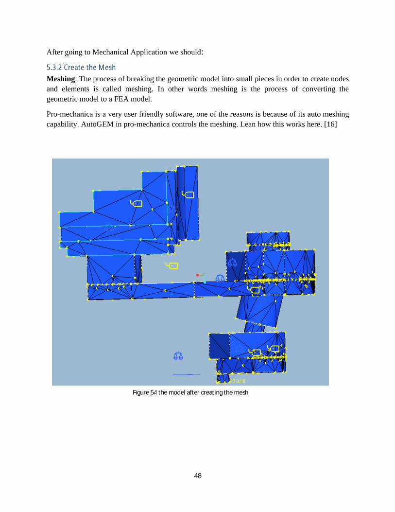
5.3 The main steps of the real simulation on PTC5.3.1 Simplifying the model (taking the third) Since the model volume is big and its mesh has a big number of elements that is what will make the simulation take a long time, it was necessary to simplify the model as much as possible by taking the third part of each piece of the model since it is symmetry.
Figure 53: The simple model
48
After going to Mechanical Application we should:
5.3.2 Create the MeshMeshing: The process of breaking the geometric model into small pieces in order to create nodes and elements is called meshing. In other words meshing is the process of converting the geometric model to a FEA model.
Pro-mechanica is a very user friendly software, one of the reasons is because of its auto meshing capability. AutoGEM in pro-mechanica controls the meshing. Lean how this works here. [16]
Figure 54 the model after creating the mesh

49
After choosing the convenient material for each part of the model (steel) and clicking on the upper button in the figure below where the red arrow we get 4474 elements which is good number for running a simulation without long time.
Figure 43: creating the mesh

50
5.3.3 Applying a forceSetting up a force on the cylindrical surface of the Actuator ring which it represent the force of Hydraulic shaft during the pulling or pushing.
After clicking the button where the red arrow we can precise the direction, the load, the reference, and the properties as we can see in the figure below.
After clicking on ok we can see that force has already applied on the surface of the actuator ring
Figure 44: creating a force for the model
Figure 45 : the applied force

51
5.3.4 Setting up the constraints
When you apply a force then you want to see the results of the applied force in the body in terms of stress, displacements etc. The main aim of any FEA is to arrest displacement completely or partially in a predetermined way.
By determining the translation degrees of freedom of every part of the model
5.3.5 Create springs
Figure 46: the main constraints of the model parts
Figure 47: the main springs of the model parts

52
5.3.6 Definition the interfacesKind of connection between the model parts to see the transmission of force between them.
5.3.7 Starting running the simulation (Static Analysis)
Figure 60: the interfaces of the model
Figure 61:the static analysis

53
5.3.8 The resultsThe gripping force without motion
After applying a force of 3KN we get gripping force of 11.17 KN
The change of gripping force during the motion
Table 1 : some values of gripping force according to the some values of speed
The speed (r.p.m)
0 500 1000 1500 2000 2500 3000 3500 4000 5000
The gripping force(KN)
11.17 11.13 11.02 10.83 10.54 10.21 9.78 9.28 8.7 7.31
Observation: we can see that the gripping force is decreasing when the speed of rotation is increasing
Figure 62: curbe of the change of gripping force according to the change of speed

54
5.3.9 Explanation
centrifugal force makes the gripping force decrease during the motion because the Jaws will get out , but since the mass of the actuator arm is bigger than the Chuck's the decreasing will not be big.
F1: centrifugal forces of the arm
F2: centrifugal forces of the jaw
Figure 63: centrifugal force [17]
Figure 48: centrifugal forces of jaw and arm
F1
F2

55
The Mathematical relation between the applied force Fa and the gripping force Fg
Fa: the applied force
Fr: the reaction force
Fg: the gripping force
When we push or pull the spindle by the force Fa, the transmitted force of the piston through the actuator ring makes a reaction force on the actuator arm Fr, and the force of jaws makes reaction force on the workpiece.
Since the model is static that means the reaction force from the workpiece equal to the gripping force Fg, as we can see in the figure above.
Fa
Fr
Figure 65 the main forces in the chuck
Fg

56
The forces triangle
According to the forces in the previous model we can make the triangle of forces
Fr = Fa / sin15
Fg = Fr / cos15
By some replacements we get the equation:
Fg = Fa (cos15/sin15) = Fa / tag (15)
15
Fa
1515
Fr
15
Fg
Fr
Fa

57
Chapter 6: Efficiency and maintenance 6.1 What Affects Grip (Clamping) Force?6.1.1 Speed (RPM) Of Chuck: As speed increases grip force decreases.
6.1.2 Jaw Height:
Figure 49: the change of gripping force according to the change of speed [18]
Figure 67: the effect of height[18]

58
6.1.3 Jaw Mass:As the mass of the top jaw increases the grip force decreases.
6.1.4 Chuck Condition:If the chuck has damage or excessive wear grip force can be impacted.
6.1.5 Lubrication (greasing):Proper chuck lubrication can increase grip force up to 50%. [18]
Figure 68 the effect of lubrication[18]

59
6.2 How to major the clamping force6.2.1 Gripping force tester GFTGripping force and speed measurement of jaw chucks and collet chucks in dynamic or static measuringmode
Measuring heads
The main heads of Gripping force tester
Figure 69: Gripping force tester GFT [9]
Figure 70: Measuring heads [9]

60
Unique features
∑ Wireless data transfer from measuring Head to reading unit (Radio433.92MHz, upto4mdistance)
∑ Measuring in safety only with closed doors
∑ Capacitors are used instead of batteries
∑ Driven Menu
∑ Display kN or lbf
∑ Languages: German, English, Italian, Spanish
∑ Software CD for displaying a gripping Force curve on the PC
∑ Measuring heads for jaw chucks and Collet chucks
Figure 71: Gripping force tester GFT [9]

61
6.2.2 Some real experiments in workshop of our department on CTX alpha machine
Majoring the
clamping force with variations of speed
Figure 50: CTX alpha machine 500 Figure 51: majoring the gripping force
Figure 52: Gripping force tester GFT
62
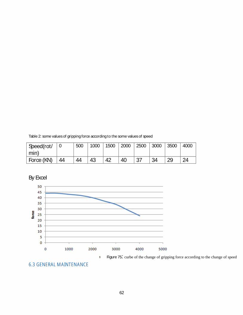
Table 2: some values of gripping force according to the some values of speed
Speed(rot/min)
0 500 1000 1500 2000 2500 3000 3500 4000
Force (KN) 44 44 43 42 40 37 34 29 24
By Excel
6.3 GENERAL MAINTENANCE
Figure 75: curbe of the change of gripping force according to the change of speed

63
∑ Before the chuck is mounted on the lathe, make sure that all the threads are thoroughly clean and free of debris. This will ensure the chuck will run true.
∑ The chuck is engineered to very close tolerances and may initially be stiff to operate. With use movement will become easier.
∑ To maintain easy jaw action, regularly spray oil onto the scroll and work lever through full range of movement.
∑ Inspect chuck regularly for buildup of dust in the scroll and jaws. Clean as required.
∑ Disassemble chuck periodically to clean & inspect to increase chuck life
∑ to maintain the chuck for a long period of time, it is necessary to lubricate the
Chuck on a regular basis. Inadequate lubrication causes malfunction at low Hydraulic pressure, reduces gripping force, affects gripping accuracy and Causes wear and seizure. Consequently, securely lubricate the chuck.
6.3.1
Grease gunK05
∑ High adhesion
∑ High resistance against coolant = long lubrication intervals
∑ Low friction coefficient =high gripping force
∑ Avoids tribocorrosion
K67
∑ For sealed chucks with constant grease lubrication
∑ Basic components: mineral oil sand lithium
∑ Without solvents[9]
Figure 53: kind of grease [18]

64
Special grease for manual and power chucks
Greasing set
Id. No. 083726
Grease gun (DIN1283) for cartridges 14Oz. (DIN1284).
∑ Also refillable from grease can 1000g
Supply range:
∑ Grease gun
∑ 1adapter flexible for high pressure grease fitting
∑ 1adapterforconegrease
6.3.2 Electronic safety control unit∑ Electro pneumatic control unit for Big Bore chucks
∑ 1/2” or 3/4” design for SP and Big Bore chucks
∑ Actuation via foot pedal or push button (not included in the supply range)
∑ Clamping control via air flow sensors
∑ Quick chuck actuation via diaphragm valves with quick exhaust
Figure 54: Greasing set [9]

65
∑ Airflow control with LED for ready and air flow. Adjustable air flow sensor sensitivity. [9]
Figure 55: Electronic safety control unit [9]

66
6.3.3 Dress and cleaning plate RPSWith 2 different fine serrations to clean and dress top jaws with fine serration inch/metric
∑ Dress and cleaning plate, hardened, precision ground serrations,
∑ 2 different serrations, on the upper and lower side of the plate. Just turn it!
∑ Rapid cleaning of the top jaws serration. Swarf and dirt is accumulated in the diagonal groove
∑ Dressing of light damage on the serration by using the grinding compound
Dressing and cleaning of serration
Figure 79: Dress and cleaning plate RPS [9]
Figure 80: cleaning of serration [9]

67
6.3.4 Boring rings ADSTo bore jaws on the clamping chuck
The
advantages of the SMW-AUTOBLOK boring rings for jaws:
∑ Complete set to bore all dia. From 20 to 150 mm.
∑ Set consisting of 36 rings Ø20 -50 mm each stepped 2mm. FromØ50-150mmsteppedin5mm increments.
∑ Clearly organized on base plate.
∑ Rings from Ø105 mm and up have 3 tapped holes for Clamping bolts to machine jaws for internal gripping.
∑ Rigid design. Ringsare10mmthick, quenched for greater durability.
∑ Mounting handle is used for the safe insertion of the smaller rings without danger of injuries.
Figure 81: Boring rings ADS [9]

68
Conclusion As a conclusion we can say that the Hydraulic Chuck is one of the best clamping devices, and inspite of the high speed of rotation it does not lose a lot of its gripping force.

69
References
[1] http://en.academic.ru/dic.nsf/enwiki/800067#History
[3] https://en.wikipedia.org/wiki/Chuck_(engineering)
[4] http://www.ladner.fr/InoZet-Compensating-6-Jaw-add-on-bridge-system.html
[5] http://atondd-bg.com/assets/userfiles/file/Bison/01.pdf
[7] Nidhin, CLAMPING 2010
[6] Aliotsy Andrianarivo ,Microsoft Word - LATHE.doc, 2008 [8] http://www.grupotdg.com/index.php/tdg_en/tdeg/productos/informaci_n_t_cnica1/tipos_de_garras/
[8] http://www.grupotdg.com/index.php/tdg_en/tdeg/productos/informaci_n_t_cnica1/tipos_de_garras/
[9] http://www.precisetooling.com.sg/catalog/smw-autoblok/Katalog_9E.pdf
[10] http://www.smwautoblok.com/index.php/sliding-jaw-chucks/hydraulic-front-end-chucks/hynd-s.html
[11] [http://www.catia.com.pl/tutorial/generative_drafting.pdf]
[12] [https://en.wikipedia.org/wiki/3D_modeling]
[13] [http://www.ptc.com/cad/3d-cad-software]
[14] [https://www.ptc.com/~/media/Files/PDFs/CAD/Creo_Advanced_Assembly_Ext_DS.ashx?la=en]
[15] http://www.ptc.com/cad/creo/simulate#sthash.eLqPXkAC.dpuf
[16] ( http://www.brighthubengineering.com/cad-autocad-reviews-tips/19614-pro-
mechanica-tutorial-part-2/#imgn_0 )
[17] http://keisan.casio.com/exec/system/1271292951
[18] http://kitagawa.com/wp-content/uploads/chucks-101_-web-blue.pdf
[19] http://en.dmgmori.com/)
[20] http://www.geiger-haag.com/hydraulicchucks.html
[21] http://www.smwautoblok.com/media//KNCSN_main.jpg