Embed Size (px)
Citation preview

rANL/CP--72367
DE92 001921
VibratioD considerations in the design of the
Advanced Photon Source at Argonne National Laboratory
Joseph A. Jendrzejczyk and Martin W. Wambsganss
Materials and Components Technology DivisionArgonne National Laboratory, Argonne, IL 60439
DISCLAIMER
This report was prepared as an account of work sponsored by an agency of t i e United Sttte*Government Neither the United States Government nor any agency thereof, nor any of theiremptovees makes any warranty, express or implied, or astumes any legal liability or responsi-bility for the accuracy, completeness, or asefulness of any information, apparatus, P™*"*. w
process disclosed, or represents that its use would not infringe privately owned rights. Refer-ence herein to any specific commercial product, process, or service by trade name, trademark,manofacturer, or otherwise does not necessarily constitute or imply hi endorsement, recom-mendation, or favoring by the United States Government or any agency thereof. Theviewsand opinions of authors expressed herein do not necessarily state or reflect thoie of theUnited States Government or any agency thereof.
The satsmnta manuKnor tat Been aumoredby a contractor of * e U. S- Govermnanrunder csneract No. W-3T-7C9-E!VC-3g.Accardingiy. the U. S. Sovemmcnt rcatra jna^cxefunwe raysicv-frpe liamt ai gublisftor rcoroducr me publishes form at ttiixcantnbuTian, or ailovw others to da *0. fcrU. S. Gncmrncitr purpo**.
To be presented at the Conf. on Vibration Control in Microelectronics. Optics, and Metrology. 1991 Symp. on Optical
Science and Engineering. November 3-8,1991, San Jose. CA.
MASTEROF THiS DOCUMENT IS UNLINK i ED

Vibration considerations in the design of theAdvanced Photon Source at Argonne National Laboratory
Joseph A. Jendrzejczyk and Martin W. Wambsganss
Materials and Components Technology DivisionArgonne National Laboratory, Argonne, IL 60439
ABSTRACT
The Advanced Photon Source (APS), a new synchrotron radiation facility being built at Argonne National Laboratory, willprovide the world's most brilliant X-ray beams for research in a wide range of technical fields. Successful operation of theAPS requires an extremely stable positron closed orbit. Vibration of the storage ring quadrupole magnets, even in thesubmicron range, can lead to distortion of the positron closed orbit and to potentially unacceptable beam emiuance growth,which results in degraded performance. This paper presents an overview of the technical approach used to minimize vibrationresponse, beginning at the conceptual stage, through design and construction, and on to successful operation. Acceptancecriteria relating to maximum allowable quadrupole magnet vibration are discussed. Soil properties are used to determineresonant frequencies cf foundations and to predict attenuation characteristics. Two sources are considered to have the potentialto excite the foundation: far-field sources, which are produced external to the facility, and near-field sources, which areproduced within the facility. Measurements of ambient ground motion, monitored to determine far-field excitation, arepresented. Ambient vibration was measured at several operating facilities within Argonne to gain insight on typical near-fieldexcitation sources. Discussion covers the dynamic response characteristics of a prototypic magnet support structure tovarious excitations, including ambient floor motion, coolant flow, and magnet power.
1. INTRODUCTION
The Advanced Photon Source (APS) is a synchrotron radiation facility under construction at Argonne National Laboratory.Upon completion in 1996, it will be the source of the world's most brilliant X-rays. The APS will be a user facility forresearch on the structure of materials. X-ray imaging, coronary angiography, and many other fields.
An overall view of the facility is shown in Fig. 1. The facility consists of a 200-MeV electron linear accelerator (linac), atungsten converter target to produce positrons, a positron linac, a positron accumulator ring (PAR),« booster synchrotron toaccelerate 450-MeV positrons to an energy of 7 GeV, a positron storage ring that is 1104 m in circumference, and manyexperimental photon beam lines utilizing die synchrotron radiation for experimental studies. The positrons circulate in thestorage ring with a current of 0.1 A and a mean positron-beam lifetime of 10 h. A cross section of the experimental hall isshown in Fig. 2. The basemat supporting the storage ring beam line is approximately twice as thick as the remainder of theexperimental hall floor; the two are separated by an expansion joint. Figure 3 illustrates one of 40 identical sectors in thestorage ring lattice, an arrangement of bending magnets and quadrupole magnets that focuses the particle beam.
Unprecedented precision and stability in aligning the storage ring magnets is a requirement for successful operation of theAPS. One source of instability is vibration of the storage ring quadrupole magnets. This can lead to distortion of thepositron closed orbit and to potentially unacceptable beam emioance (which is related to the size of the beam) growth. This,and the fact that vibration-induced problems have been experienced in other similar operating synchrotron radiation sources,1-2
provides the motivation for the subject studies.
2. VIBRATION CRITERIA
Vibration criteria were developed on the basis of the requirement that emiuance growth be limited to 10%. Of the variousmagnets in the storage ring magnet lattice, the quadmpole magnets have the most significant effect on beam stability andemiaance growth. Three different vibration scenarios were considered with respect to the quadrupole magnets: (1) vibrationof a single quadrupole within the storage ring, (2) random vibration of all quadrupoks in the ring, and (3) die hypothetical

case of a plane wave sweeping across the site and the quadrupoies following the motion of the plane wave. The maximumallowable peak vibration amplitudes corresponding to these three vibration scenarios are given in Table 1. The criteriaassociated with the passage of a plane wave is dependent on wavelength, or alternatively on frequency, given the wave speed.The wave speed used in Table 1 is that measured as a pan of the geotechnical investigation at the APS site.
From Table 1. it can be seen that the most stringent criteria are those associated with random vibration of the storage ringquadrupoies. As such, these criteria will be taken as the vibration criteria to be met for vibration amplitudes. Relative tofrequencies, low-frequency vibrations (<10-20 Hz) can be controlled with steering magnets using feedback systems, providedthe vibration amplitudes arc within the dynamic range of the controllers. High-frequency (>10-20 Hz) vibration amplitudes,on the other hand, are out of the range of the controller, and therefore must be limited to ensure that beam emittance growthwiil not exceed the prescribed value.
The horizontal and vertical displacements of Table 1 are peak values; allowable root-mean-square (RMS) levels wiil be lower,depending on the characteristics of the signal, e.g., sinusoidal or random.
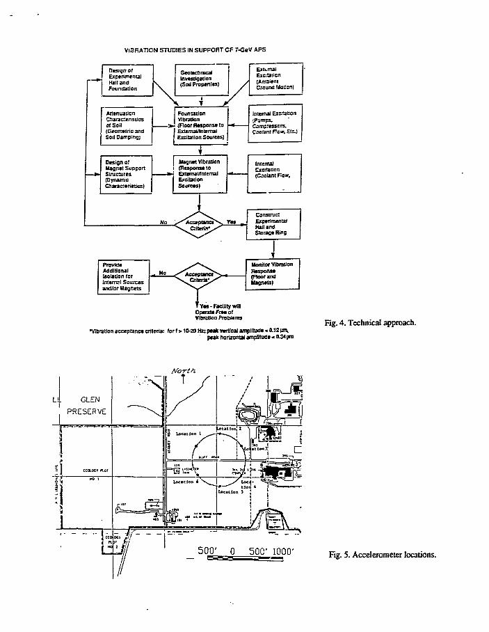
3. TECHNICAL APPROACH
The technical approach is illustrated in flow-diagram format in Fig. - . The major thrust of the studies is to estimate magnetvibration from both near-field (internal) excitation sources and floor motion, to assess the estimated response relative to thevibration criteria, and—based on that assessment—to make a decision as to how to proceed with design and construction orwith redesign.
As illustrated in Fig. 4T vibration of the quadrupole magnets will be determined by the dynamic characteristics (naturalfrequencies, modes, and damping) of the magnet/girder/support assemblies and the excitation sources. Internal excitationsources include the coolant flow in the magnet, header, and return piping. The magnet support system will also respond tomotion of the experimental hall floor slab, in particular the storage ring basemat.
Vibration of the basemat, in turn, will be determined by the design of the experimental hall and foundation, soil propenies atthe site, far-field excitation in the form of ground motion due to natural and cultural sources, and internal (to the experimentalhall) excitation associated with pumps, compressors, HVAC equipment, and the like. Program elements defined in Fig. 4 andrelating to the mction of the experimental hall floor slab and storage ring basemat, design to minimize floor motion, andvibration studies of the storage ring magnet/support assemblies have been addressed and reported.^"^ The results of theseinvestigations are summarized in the following sections.
Table I. Vibration criteria: maximum allowable vibration amplitudes
Vibration Tvpe
Single Quadrupole
Random (all quadrapoles)Plane Wave (v = 306 m/s; fin Hz)
f<2.22.2 < f < 4.64.6<f<7.7
7.7<f< 13.5
f > 13.5
DtSDlacetnent Cm
Horizontal
2.20.34
16.1
16.116.1
16.1-0.90
0.90
ml
Vertical
1.29
0.12
4.4
4.4-0.28
0.28
0.28
0.28

4. GEOTECHMCAL INVESTIGATION
A geotechnical investigate thai used more than 28 boreholes was completed.3"5 Field testing, crosshole seismic testing,and laboratory testing were pan of this investigation. A soils consultant performed the soil borings, field tests (includingcrosshole seismic), and laboratory tests. The Illinois State Geological Survey was responsible for collecting regionalgeological and geotechnical data such as ground-water levels, and for measuring the continuity of subsurface bedrock.
The site soil profile, from surface to bedrock, is as follows:
Fill materials consisting of silty clay were encountered at various locations.
Weatherer. till was encountered in all of the boring extending to depths of 10 to 24 ft it consists of hard to very stiff brownsilty clay.
Umveathered till was encountered underlying the weathered all and consists of grey silty clay containing traces of sand, gravel,and shale. It has a low plasticity and generally a hard to very stiff consistency.
Oucwask deposits consisting of sand, silt, and occasionally grave! were encountered sporadically across the site. Thesedeposits were relatively thin and discontinuous.
Lemont drift was encountered underlying the unweathered till and extending to the bedrock surface; it consists of a dense toextremely dense formation of sand, silt, and gravel.
Bedrock, consisting of dolomitic limestone, was encountered unriedying the Lemont drift. Bedrock surface elevation variedfrom 613 to 643 ft.
Among other things, the results provided information on foundation bearing capacities and settlement. It was concluded thatbearing soils found at design subgrade level are generally suitable (competent and stable) for support of the storage ringbasemat and experimental hall basemat on grade. Results from die crosshole seismic testing gave information on shear andcompressional wave speeds that, in turn, allowed computation of soil moduli values; such information is needed for analyzingsoil/foundation interaction.
5. SOIL/FOUNDATION INTERACTION
Soil/foundation interaction was analyzed to develop an understanding of the dynamic characteristics (in particular, resonantfrequencies and damping) to be expected with the slab on grade construction. * * EquivaJent-Iumped-parameter modeling basedon elastic-half-spac; theory was used with the soil shear modulus and density obtained from the geotechnical investigation.The modeling was evaluated with available test data on large foundations and was shown to be generally applicable. Thesignificant conclusion from the analysis is that the large plan dimensions of the APS storage ring basemat and experimentalhall floor slabs result in very large damping values; this, in turn, implies that dynamic magnification factors will benegligible. As a consequence, amplification of ground motion as 3 result of soil/foundation interaction dynamics is not aconcern. Conservatively, the floor can be assumed to follow the motion of the ground. However, experience suggests thatwith large slabs, floor motion will actually be smaller than ground motion due to, among other things, "waveformaveraging."1^
«. AMBIENT GROUND MOTION
There are two sources of ambient ground motion: near-field sources, which are generated within the site, and far-field sources,which are generated external to the site. Ground motion may occur in response to natural sources such as microtremors or tocultural sources such as road and/or rail traffic, reciprocating machinery, unbalanced rotating machinery, mining, and the like.The near-field sources can be considered to be within the control of the APS facility and can be minimized or eliminated byproper design. Because far-field sources may or may not be controllable (depending on source, location, and transmissionpath), a detailed investigation of ambient ground motion was required to ensure site acceptance. Surveys of ground motionwere made in the vicinity of various Argonnc buildings external to the APS s i tc ,^ as well as at the APS site. 8-10

At the APS site, six simultaneous measurements were made on what would correspond to the circumference of the storagering.8 Acceterometers were oriented vertically and mounted on 24-in. long steel rods driven into the ground at the locationsshown in Fig. 5. The accsierometers were connected to double integrator circuits and an FM tape recorder via 750-ft lengthsof coaxial cable. Continuous recordings of displacement-time data were made over a 24-h period. The data were thenanalyzed with spectrum analysis techniques, integrated over 8-min intervals to obtain RMS values, and then plotted as afunction of time; typical results are shown in Figs. 6 and 7.
In Fig. 6, several interesting observations can be made from the RMS displacement: (1) Ground motion is considerablyhigher at location 2, which is approximately 400 ft closer to a building than is location 1; this is a good example of howdistance can provide attenuation. (2) An increase in ground motion, as a function of time, at location 2 can be related to thework day (an inherently active period) at Argonne. (3) Several large "spikes" are the result of transients. (4) Overallamplitude at either location is well below the established criteria. The frequency content of the ground motion displacement-time signals includes several distinct frequencies: low-frequency integration noise (<4 Hz), 7.81 Hz, and 10.5 Hz. The 7.81-and 10.5-Hz components are thought to be associated with the vibration of large civil structures, such as buildings.
Total displacement at locations 3 and 4 for the corresponding time period is shown in Fig. 7. One can readily observe that atapproximately 19:00 on Wednesday, a iiarge increase in ground motion occurs at both locations. The amplitude correlationbetween each location is clearly seen. A subsequent frequency response analysis showed that the large amplitude is associatedwith 18.4- and 60-Hz displacement components. Because it is present only at locations 3 and 4, it is assumed to be a near-field source; as a result of soil attenuation characteristics, a far-Held source would result in detectable ground motion at theother locations as well. Because these components of ground motion exceeded the allowable vibration amplitude criteria, withfrequencies above the upper limit for correction with die feedback system and steering magnets, the displacement amplitude atlocation 3 was monitored for a 1.5-year period." However, during mat period, only one positive occurrence was detected andthat was within one month of the initial measurement. Frequency analysis showed that the 7.81- and 10.5-Hz displacementsare present at a higher level at locations 3 and 4 than at location 2.
Several transients were observed during the 24-h monitoring period. The transients can be categorized into three types: (1)Near-field, low-energy, observed only on a specific transducer, locally generated close to a transducer, such as would resultfrom human activity. (2) Near-field, medium-energy, observed at all transducer locations, with a wave velocity of 1,100 ft/s,which could result from a vehicle driving over a discontinuous pavement (3) Far-field, high-ewrgy, observed at all locations,with a wave velocity of >18,000 ft/s. The amplitudes of the various transients were relatively high, up to 1.2 pm peak-to-peak; however, with a characteristically short time duration and a large frequency content, they will contribute very little tothe response of a large massive mechanical structure.
7. VIBRATION AT AN OPERATING FACILITY
To gain insight into the vibration levels that might be expected at an accelerator facility located at Argonne, a vibrationsurvey was performed at the Laboratory's Intense Pulsed Neutron Source (IPNS).^ This facility has many components thatare similar to those in the APS storage ring lattice, such as bending magnets, quadrupole magnets, magnet supportassemblies, coolLig water headers, and cooling water flow through the magnet coils. The survey included measurements ofexperimental hall floor vibration at several locations, floor vibration at the base of the magnets, and magnet vibration. Todetermine the effect of various types of equipment on vibration levels, vibration measurements were made with selected IPN'Sequipment operating and not operating.
Among other things, the survey led to the conclusions that (1) the magnet/support assemblies can provide dynamicamplification of floor motion, and (2) energizing the quadrupole magnets results in increased vibration levels by a factorgreater than 2. Nevertheless, in the frequency range of 10 to 250 Hz, measured RMS vibration levels were in the range of0.02 to 0.08 (im, well within the allowable limits established for the APS quadruples. Further, energization of the APSquadrupole magnets will probably not contribute as much to the vibration level because their input power is controlleddifferently than in the IPNS.
The effect of coolant flow on magnet and floor motion was also measured. Displacement response of the bending magnet tocoolant flow was negligible, while a measurable, but small, increase was detected in the response of the quadrupole magnet;no increase was detected in floor response.

8. DYNAMIC RESPONSE OF STORAGE RING GIRDER ASSEMBLY
The APS storage ring is divided into 40 sectors, each consisting of 5 individual magnet support sections for a total of 200sections. Typically, there will be two groups of 80 and one group of 40 similar sections. A cross section of a quadrupolemagnet support assembly is shown conceptually in Fig. 8, while a side view of a typical section is shown in Fig. 9. Thestorage ring magnets are mounted on girders that, in turn, are supported on jackscrcw/pedestal support assemblies. It shouldbe noted that the various sections also include beam-position monitors, vacuum-chamber support structures, and vacuumpumps; these are not shown in Figs. 8 and 9.
The vibrational characteristics (natural frequencies, modes, and damping) of the magnet/girder support system will determinethe response of the magnets to floor motion and coolant flow. Dynamically, the storage ring magnet/support systems arevery complicated, with many degrees of freedom, large mass (typically >6,800 kg), and a high center of gravity. The heightof each section can be varied 0.038 m from the mean height of 1.4 m with the leveling jacks. Also, the height of theindividual magnets can be varied with small jackscrews. The girder and 'Tagnet jacks represent the most significant unknownin predicting the frequency characteristics of the overall system.
From the standpoint of positron beam stability and control, two elements 2re very critical: (1) the position of the beam-position monitors, which are mounted on the vacuum chamber, relative u) the positron beam; and (2) the position of thequadrupole magnets with respect to the positron beam. If ths beam-position monitors move because of vacuum-chambermovement, the feedback control system would sense that motion as a change in beam position and initiate an unwantedcorrection. Any extraneous motion of the quadnipole magnets will result in unwanted motion of the beam. If the dynamicrange and frequency response of the feedback control system is not exceeded, the effect of quadrupole magnet motion can becompensated for.
Perturbation of the storage ring quadrupole magnets, and hence the positron beam, can be caused by three different excitationsources. Motion of the storage ring basemat, in response to ambient ground motion and/or equipment operating within theexperimental hall, may couple through the girder/support assemblies to the quadrupole magnets or vacuum chamber. Thesecond potential source oi motion is equipment directly mounted to the girder section, because such equipment c?a give riseto eddy-current response between the vacuum chamber and magnets. The third source is coolant flow through the manifoldsand magnet windings.
At present, the magnets and many of the other components to be mounted on the girder are in the design stage. As aconsequence, a complete system was not available to test. To circumvent this problem and to obtain design information at anearly date, concrete shielding blocks were used to simulate the magnet masses. As prototype components become available,they are evaluated relative to the overall vibration response and the established vibration criteria, thereby providing the optionto redesign if unacceptable response is observed. In the following, vibration studies of the storage ring magnet/supportassemblies and vacuum chamber are summarized.
8.1. Magnet/support assembly
A vibration study, which consisted of an integrated analytical/experimental investigation of the APS storage ringmagnet/support assembly, was performed. ̂ Two girder support configurations were analyzed and tested. Theoreticalvibration frequencies were calculated from a finite-element code, based on a Jack stiffness that was back-calculated fromexperimental measurements. Natural frequencies and mode shapes were determined from measurements made with a structuraldynamics measurement analysis program. Table 2 shows a comparison between theoretical and experimentally measurednatural frequencies for one support configuration. The experimental out-of-plane (horizontal) low-frequency modes (5.0 and8.3 Hz) compare well with the theoretical. Measured damping factors associated with these modes are 33% and 17%,respectively. The 53.6-Hz mode is a bending mode with a damping factor of 2.75%. Measured in-plane (vertical) modes of36.8 and 87.6 Hz are girder bending modes, having damping factors of 5.8% and 1.75%, respectively.
While several response frequencies were observed, the associated damping factors were reasonably high, resulting in smallmagnification factors. Assuming that the dynamic range of the feedback control system is sufficiently large, the 5.0- and 8.3-Hz responses can be controlled. Because the girder is a relatively "siifT member, there is a question as to whether sufficientenergy can be coupled to it to excite the bending modes.
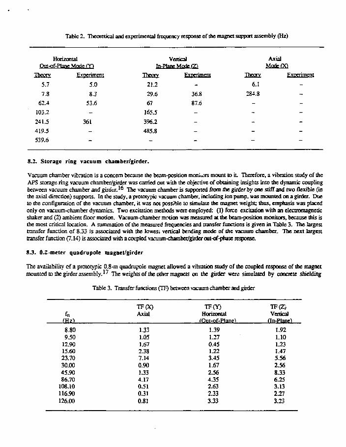
Table 2. Theoretical and experimental frequency response of the magnet support assembly (Hz)
Horizontal Vertical AxialOut-of-Plane Mode m In-Plane Mote (T) ModeOO
Theory Experiment
6.1
284.8
Theory
5.7
7.862.4
103.2
241.5
419.5
539.6
Experiment
5.08.3
53.6
-
361—
VerticalIn-Plane Mode (T)
Theory
21.2
29.6
67
165.5
396.2
485.8
Experiment
_
36.8
87.6
--
8.2. Storage ring vacuum chamber/girder.
Vacuum chamber vibration is a concern because the beam-position monitors mount to it Therefore, a vibration study of theAPS storage ring vacuum chamber/girder was carried out with the objective of obtaining insights into the dynamic couplingbetween vacuum chamber and girder. ̂ The vacuum chamber is supported from the girder by one stiff and two flexible (inthe axial direction) supports. In the study, a prototypic vacuum chamber, including ion pump, was mounted on a girder. Dueto the configuration of the vacuum chamber, it was not possible to simulate the magnet weight; thus, emphasis was placedonly on vacuum-chamber dynamics. Two excitation methods were employed: (1) force excitation with an electromagneticshaker and (2) ambient floor motion. Vacuum-chamber motion was measured at the beam-position monitors, because this isthe most critical location. A summation of the measured frequencies and transfer functions is given in Table 3. The largesttransfer function of 8.33 is associated with the lowest vertical bending mode of the vacuum chamber. The next largesttransfer function (7.14) is associated with a coupled vacuum-chamber/girder out-of-phase response.
8.3. 0.2-meter quadrupole magnet/girder
The availability cf a prototypic 0.8-m quadrupole magnet allowed a vibration study of the coupled response of the magnetmounted to the girder assembly.^ The weights of the other magnets on the girder were simulated by concrete shielding
Table 3. Transfer functions (TF) between vacuum chamber and girder
fnfHzt
8.809.50
12.9015.6023.7030.0045.9086.70
108.10116.90126.00
TF(X)Axial
1.331.051.672.387-140.901.334.170.510.310.81
TF(Y)Horizontal
fOut-of-Planei
1.391.270.451.223.451.672.564.352.632.333.33
TF(Z>Vertical
fin-Plane")
1.921.101.231.475.562.568.336.253.132.273.23
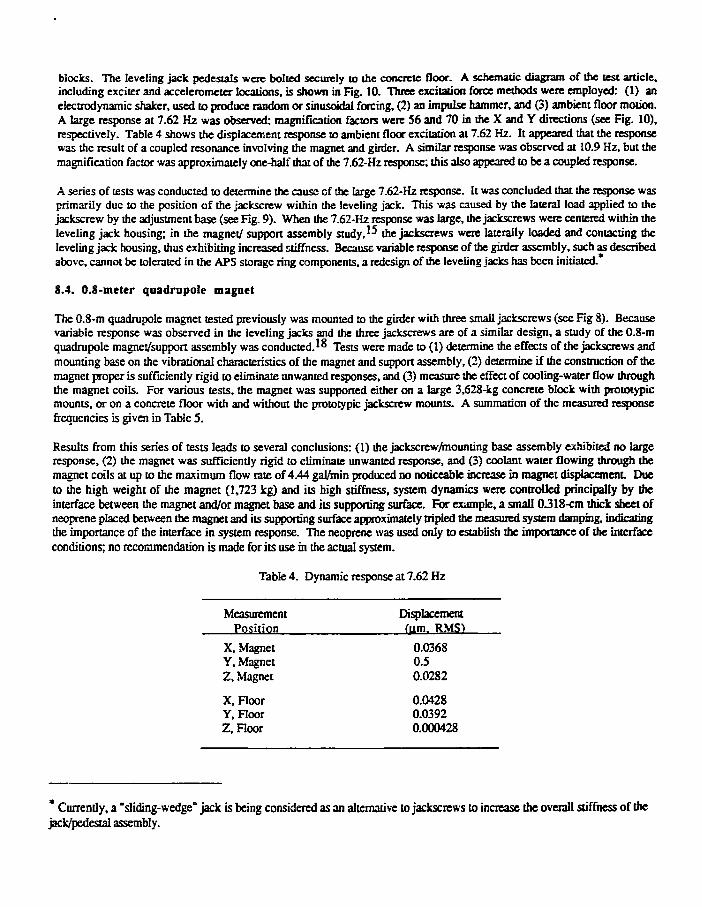
blocks. The leveling jack pedestals were bolted securely to the concrete floor. A schematic diagram of the test article,including exciter and accelerometer locations, is shown in Fig. 10. Three excitation force methods were employed: (1) anelectrodynamic shaker, used to produce random or sinusoidal forcing, (2) an impulse hammer, and (5) ambient floor motion.A large response at 7.62 Hz was observed: magnification factors were 56 and 70 in the X and Y directions (see Fig. 10).respectively. Table 4 shows the displacement response to ambient floor excitation at 7.62 Hz. It appeared that the responsewas the result of a coupled resonance involving the magnet and girder. A similar response was observed at 10.9 Hz, but themagnification factor was approximately one-half that of the 7.62-Hz response; this also appeared to be a coupled response.
A series of tests was conducted to determine the cause of the large 7.62-Hz response. It was concluded that the response wasprimarily due to the position of the jackscrew within the leveling jack. This was caused by the lateral load applied to thejackscrew by the adjustment base (see Fig. 9). When the 7.62-Hz response was large, the jackscrews were centered within theleveling jack housing; in the magnet/ support assembly study, ̂ the jackscrews were laterally loaded and contacting theleveling jack housing, thus exhibiting increased stiffness. Because variable response of the girder assembly, such as describedabove, cannot be tolerated in the APS storage ring components, a redesign of the leveling jacks has been initiated.
8.4. 0.8-meter quadrupole magnet
The 0.8-m quadrupole magnet tested previously was mounted to the girder with three small jackscrews (see Fig 8). Becausevariable response was observed in the leveling jacks and the three jackscrews are of a similar design, a study of the 0.8-mquadrupole magnet/support assembly was conducted.1** Tests were made to (1) determine the effects of the jackscrews andmounting base on the vibrational characteristics of the magnet and support assembly, (2) determine if the construction of themagnet proper is sufficiently rigid to eliminate unwanted responses, and (3) measure the effect of cooling-water flow throughthe magnet coils. For various tests, the magnet was supported either on a large 3,628-kg concrete block with prototypicmounts, or on a concrete floor with and without the prototypic jackscrew mounts. A summation of the measured responsefrequencies is given in Table 5.
Results from this series of tests leads to several conclusions: (1) the jackscrcw/mounting base assembly exhibited no largeresponse, (2) the magnet was sufficiently rigid to eliminate unwanted response, and (3) coolant water flowing through themagnet coils at up to the maximum flow rate of 4.44 gal/min produced no noticeable increase in magnet displacement Dueto the high weight of the magnet (1,723 kg) and its high stiffness, system dynamics were controlled principally by theinterface between the magnet and/or magnet base and its supporting surface. For example, a small 0.318-cm thick sheet ofneoprene placed between the magnet and its supporting surface approximately tripled the measured system damping, indicatingthe importance of the interface in system response. The neoprene was used only to establish the importance of the interfaceconditions; no recommendation is made for its use in the actual system.
Table 4. Dynamic response at 7.62 Hz
Measurement DisplacementPosition ftim. RMSt
X, Magnet 0.0368Y, Magnet 0.5Z, Magnet 0.0282
X, Floor 0.0428Y, Floor 0.0392Z, Floor 0.000428
* Currently, a "sliding-wedge" jack is being considered as an alternative to jackscrews to increase the overall stiffness of thejack/pedestal assembly.

Table 5. System response frequencies for the 0.8-m quadrupole magnet
Frequency Hz
8.0111.5213.8716.2118.5529.6931.25
Svstem Frequency Response
Building responseShielding block
Magnet, Y-direction, rigid body modeAmbient response on magnet
Magnet, X-direction, rigid body modeMagnet, Z-directionMagnet, Z-direction
9. CONCLUSIONS
The ambient ground motion study indicates that with the exception of the 18- and 60-Hz components, the site is quiet and issuited to the construction of a vibration-sensitive facility such as the APS. Because the 18- and 60-Hz displacements weredetected only on one occasion (summer of 1988) and not later, they are assumed to be of a temporary nature and not a long-term concern. Very large damping values will be associated with the APS storage ring basemat and experiment hall floorslab, ensuring that dynamic magnification of ground motion will be negligible. Further confidence in the ability to constructa facility at the Argonne site that meets the stringent vibration criteria set forth was provided by the results of the vibrationstudy of an operating accelerator, which demonstrated that measured response was generally within the allowable rangeestablished for the APS. Dynamic response measurements on prototypic APS storage ring components identified a largeresonant response due to excessive clearances in the leveling jacks. This potential problem will be circumvented by redesignof the jacks. Finally, because accurate analytical modeling of system dynamics is not possible, further vibration testing ofcompleted assemblies will be necessary and is being planned.
Based on the information developed to date, we can conclude that a continuing program of cautious design, testing, andmonitoring will result in successful operation of the APS facility from a vibration standpoint. Here, cautious design includesensuring that any equipment, within or near the experimental hall, is properly balanced and provided with vibration isolation.
10. ACKNOWLEDGMENTS
This work is supported by the U.S. Department of Energy under Contract W-31-109-Eng-38. Professor F. E. Richart, Jr.,serves as a consultant to the APS Project on ground motion, soil-structure interaction, and foundation design, and providedvaluable contributions to the study. The authors also acknowledge Dr. S. S. Chen and Mr. R. K. Smith for theircontributions to the analysis and test phases, respectively, of this work.
10. REFERENCES
1. K. Hake, "Correlation between the Movement of the Light Source Building and the Vibration of the SynchrotronRadiation Axis," Japanese J. Appl. Physics, vol. 26, no. 2, pp. 285-288,1987.
2. J. Godel, Brookhaven National Laboratory, personal communication, June 1989.3. "Subsurface Exploration and Geotechnical Engineering Evaluation for Proposed 7-GeV Advanced Photon Source,"
STS Consultants. Northbrook. IL, Final Report. STS Project No. 25229, May 20,1988.4. "Title II - Subsurface Exploration and Geotechnical Engineering Evaluation for Proposed 7-GeV Advanced Photon
Source (APS)," STS Consultants, Nonhbrook, IL, Final Report, STS Project No. 25229-B. April 30,1990.5. J. A. Jendrzejczyk and M. W. Wambsganss, "Surface Measurements of Shear Wave Velocity at the 7-GcV APS Site,"
Argonne National Laboratory Report LS-129, Dec. 1987.6. J. A. Jendrzejczyk and R. K. Smith, "Building-Soil Vibration Coupling," Argonne National Laboratory Report
LS-79. Jan. 1987.7. J. A. Jendrzejczyk, M. W. Wambsganss, and R. K. Smith, "Ambient Ground Motion Measurements at Argonne
National Laboratory over Extended Time Periods," Argonne National Laboratory Report LS-111, March 1988.

8. J. A. Jendizejczyk, Z. Nagy, and P.. K. Smith, "Ambient Ground Motion at the 7-GeV APS Site at Argonne NationalLaboratory over Extended Time Periods." Argonne National Laboratory Report LS-136, Dec. 1988.
9. J. A. Jendizejczyk, M. W. Wambsganss, and R. K. Smith, "Surveillance of 18 Hz and 60 Hz Components of GroundMotion at the APS Site," Argonne National Laboratory Report APSIINIV1B190-1, March 1990.
10. H. Amick and C. G. Gordon, "Site Vibration Survey - Advanced Photon Source - Argonne National Laboratory,"Acemech Inc.. Report No. 18, Aug. 1989.
11. M. W. Wambsganss, "Dynamic Analysis of the 7-GeV APS Experimental Hall Foundation Based on EquivalentLumped Parameter Modeling," Argonne National Laboratory Report APSHNIVIBI89-1, Jan. 1989.
12. J. A. Jendrzejczyk, R. K. Smith, and M. W. Wambsganss, "Vibration Survey of IPNS Beam Line Magnets andExperimental Hall," Argonne National Laboratory Report LS-89, April 1987.
13. M. W. Wambsganss, "Preliminary Dynamic Analysis of Conceptual Design of Magnet/Support System for the APSStorage Ring," Argonne National Laboratory Report. APSUN/VfB/89-2, June 1988 (Rev. May 1989).
14. S. S. Chen and M. W. Wambsganss, "Vibration Analysis of APS Magnet/Support Systems Based on the FiniteElement Method," Argonne National Laboratory Report APSI1NIV1B189-3. March 1989.
15. M. W. Wambsganss, J. A. Jendrzejczyk, and S. S. Chen, "Vibration Study of the APS Magnet SuppoaAssemblies," Argonne National Laboratory Report APSiIN/VIB/90-3, Nov. 1990.
16. J. A. Jendrcejczyk, M. W. Wambsganss, and R. K. Smith, "Vibration Study of the APS Storage Ring Vacuum-Chamber/Girder Assembly," Argonne National Laboratory Report APSUNIVIBI91-1, Feb. 1991.
17. J. A. Jendrzejczyk, M. W. Wambsganss, and R. K. Smith, "Vibration Study of the APS Storage Ring 0.8 MeterQuadrupole/Girder Assembly," Argonne National Laboratory Report APSHMVIB/91-2, May 1991.
18. J. A. Jendrzejczyk, M. W. Wambsganss, and R. K. Smith, "Vibration Study of the APS Storage Ring 0.8 MeterQuadrupole Magnet/Magnet S upport Assembly," Argonne National Laboratory Report APSUNIVIBI91-3, June 1991.
19. H. Amick, Acentech Inc., personal communication, Nov. 1990.
Fig. 1. General layout of APS facility.

27 »eTES SU3 ?T.
t CF E<P. '«JL
, BiiMjvvc.vnf
AC O 0 T - , 1
1 ±4:~JZ.
C60 •E7E? I
t;i oFig, 2. Cross section of experimental hall.
I.D. MJ NeG Pumping-, [M]
4- t l
I/1
1 2 3 4 5 6Horizontal Horizonta! Oipole With Sextupole and Crotch Quacrupole& Vertical Correction Trim Coil Vertical Absorber JviognetCorrection Magnet Correction' w ° S n e t [MJ = Beam Position Monitor
P = Lumped Ion and • Neg Vacuum Pump
Fig. 3. Typical sector instorage beam line.
VIBRATION STUDIES IN SUPFORT CF 7-GeV APS
Design ofExperimentalKail andFoundation
AttenuationCharacteristicsof Soil
) (Geometric andI Soil Damping)
Design orMagnet SupportStructures(DynamicCharacteristics)
ProvideAdditionalIsolation forInternal Sourcesand/or Magnets
GeotectinicilInvestigation(Soil Properties)
I Hagnet Vibration• (Response to» Extemal/lntemal
ExcitationSources)
ExternalExcitation(AmcientGround Motion!
\ 1 *FoundationVibration(Floor Response to
I Extemal/lntemal' Excitation Sources)
Internal Excitation(Pumps,Compressors.Coolant Fc«r, E!ci
InternalDtcaucn(Cadant flow.
ConstructExperimentalHail andStorage Ring
Henitor VibrationResponse(Floor andMagnets)
Yes-Facility winOperate Free ofVlbrztlon Problems
•Vibration acceptance criteria: for f > 10-20 Hz; peak vertical amplitude < 0.12 pn,peak horizontal amplitude < 0J4 jm
Fig. 4. Technical approach.
NoTth
LI
500' 0 50C 1000 Fig. S. Acceleromeler locations.

Total Displacement "Wideband" (4-tocHz)
Fig. 6. Total dispfacement for locations I and 2.
SI \m WEDNESDAY ST2S» THURSDAY
Total Displacement-Wideband" (4-1<J0Hz)
o saa 'aoa njos iaaa nao ' isaoKg. 7. Total displacement for locations 3 and 4.
Si t/as WEDNESOAV
Fig. S. APS storage ring magnet support assembly,cross-sectional view.

Jl i
'
EASE
Fig. 9. APS storage ring magnet support assembly,side view.
Fig. 10. Schematic diagram of magnet/girder test article.