Embed Size (px)
Citation preview
MASTER CERTIFICATE COURSE IN AUTOMATION AND PROCESS
CONTROL (MCCAPC)
Ministry of Micro, Small and Medium Enterprises, New Delhi (MSME-Technology Centre)

Page | 1
COURSE/MODULE TEMPLATE
COURSE NAME: MASTER COURSE IN AUTOMATION AND PROCESS CONTROL
COURSE CODE: MSME/MCCAPC/00
COURSE OUTCOMES: After completion of course Student should be able to:
1. Describe, specify & care of maintenance of common tools that is involved in maintenance work. Use appropriate Electrical protecting devices, measuring instruments etc. at appropriate place.
2. Perform Preventive & Break down Maintenance of different machines (turning, milling, grinding, drilling, radial grinding etc.),
3. Identify different parts of machine, study working mechanism of different machines, select, check and connect cable in control panel
4. Design & configure basic pneumatics components.
5. Design various circuits by using different valves, for industrial control
6. Control the Pressure using pressure control valve for controlling linear actuators or rotary actuator.
7. Configure of PLC hardware modules in the rack and setup the communication between PLC modules.
8. Install the programming software & driver tools. Program the PLC with LAD Programming with Bit Operand, Block Operands.
9. Connect the Remote I/O, Profibus PLC and Ethernet Profibus PLC, Logic Board Simulation, Interfacing of I/O devices and Fault Monitoring systems.
10. Configure the communication console parameter with Controller (PLC), Configure the communication console parameter with MTU.
11. Create a single user and multi user SCADA Project. Activate & Deactivate a Project. Copy a Project.
12. Create process picture of conveyor control logic & Simulate using simulator. Design PC-Based HMI. Interface different field devices with SCADA system & monitoring process
13. Establish Communication link of different PLC modules with HMI.
14. Select & configure different hardware for HMI by TIA Portal, Use Tag Management for Controlling Different I/P & O/P by Graphical Screen, HMI Based I/P & O/P Control by Tia Portal, use of Lab View, KUKA robot operation.

Page | 2
THEORY HOURS: 260 PRACTICAL HOURS: 560 THEORY MARKS: 1100 PRACTICAL MARKS: 1000
Unit No. Unit Name Unit level outcomes Contents (chapters/topics) TH hours Marks
UNIT-I
Electrical
Hardware Logic
Control
Design the Electrical Hardware Logic Control System to control different electrical actuators.
Electrical safety. Measuring instrument. Introduction to control. Types of switches. Types of electrically active switches. Creating and testing control and power circuit.
20 100
UNIT-II Electrical
Machines
Perform Electrical Machine operations in various power supply & ratings.
Single phase and three phase connection. Function and working principle of different types of motors. Oscilloscope. Frequency generator, counter &
wave shaping.
Power measurement method.
Transformer.
Load characteristics.
20 100
UNIT-III Sensor and
transducer
Design electrical circuit using specified based on application.
Study of strain measurement.
Characteristics of analog sensors. 20 100
UNIT-IV Pneumatics &
Hydraulics system
Design Pneumatics & Hydraulics circuit for simultaneous plant applications.
Valves and cylinders demonstration. Tubing valves and cylinders. Flow control valves. Dual pressure valves Shuttle valves. Electrical application with pneumatics and hydraulics. Interfacing with plc.
30 100
UNIT-V Programmable
Logic Controller
Design Automation Process & Control System By Using Programmable Logic Controller.
NO NC programming for switches. Memory bit application. Move and comparator. Timer and counter application. Plc interfacing. Analog signal application. FBD and STL programming. Networking topology. Plc fault finding process. Plc maintenance.
30 100
UNIT-VI (a)
Embedded
System
Design embedded C-programming to operate microcontrollers and other peripheral devices.
Introduction to embedded system. Assembly and embedded c-programming. Interfacing of peripheral devices.
20 100
UNIT-VI (b)
Machine
Maintenance
Perform different conventional & non-conventional Machine Maintenance.
Demonstration on tools. Circuit breakers. Process to dismantle machines. Fault finding methods. Preventive and breakdown maintenance. Facing operation. Plain and step turning operation. Zigzag facing operation. Tracing signal by LAD. Coolants and Lubricants.
30 100
UNIT-VII SCADA & HMI
Design GUI based control by SCADA & HMI
Installation of scada software. Creating single user project. Creating multi-user project. Graphics designer tools. Process to set tags. Windows object. Analog process.
20 100

Page | 3
Moving object. Alarm logging and tag logging. HMI configuration.
UNIT-VIII TIA-Portal
Demonstrate on hardware of
TIA-portal as s7-1200 PLC.
Introduction to the software. Creation of different types of blocks. IEC Timers and counters application. Analog process. PLC to PLC communication.
20 100
UNIT-IX
Distributed
control system by
PCS-7
Create programs for distributed control system and create report designing for the same.
Single user project. Process object. Plant hierarchy setting. Different types of blocks. Os compiling.
20 100
UNIT-X
Lab View Interface any type of electrical hardware with software for its automatic application.
Introduction to the software. Types of data with arguments. Case structure. Shift register. Flat sequence.
20 100
UNIT-XI Robotics Perform PLC programming to operate KUKA robot automatically.
Introduction and scope of robotics. Study of KUKA SIM-PRO software. Study of angular limits.
10 100
UNIT-XII AUTOCAD
Electrical
Prepare electrical drawing
using AutoCAD Electrical.
Introduction on AutoCAD. Co-ordinate systems. Types of commands and function keys. Modify menu bar & draw menu bar, layer, text & dimension. 2-d and 3-d drawing. E-cad introduction. Component library.
30 100
UNIT-XIII Communication Skill
Improve personal skills. Introduction to soft skills. Basics of communication. Introduction to nonverbal communication.
10 100
Page | 4
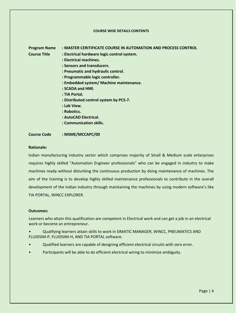
COURSE WISE DETAILS CONTENTS
Program Name : MASTER CERITIFICATE COURSE IN AUTOMATION AND PROCESS CONTROL
Course Title : Electrical hardware logic control system.
: Electrical machines.
: Sensors and transducers.
: Pneumatic and hydraulic control.
: Programmable logic controller.
: Embedded system/ Machine maintenance.
: SCADA and HMI.
: TIA Portal.
: Distributed control system by PCS-7.
: Lab View.
: Robotics.
: AutoCAD Electrical.
: Communication skills.
Course Code : MSME/MCCAPC/00
Rationale:
Indian manufacturing industry sector which comprises majority of Small & Medium scale enterprises
requires highly skilled “Automation Engineer professionals” who can be engaged in industry to make
machines ready without disturbing the continuous production by doing maintenance of machines. The
aim of the training is to develop highly skilled maintenance professionals to contribute in the overall
development of the Indian industry through maintaining the machines by using modern software’s like
TIA PORTAL, WINCC EXPLORER.
Outcomes:
Learners who attain this qualification are competent in Electrical work and can get a job in an electrical work or become an entrepreneur.
• Qualifying learners attain skills to work in SIMATIC MANAGER, WINCC, PNEUMATICS AND FLUIDSIM-P, FLUIDSIM-H, AND TIA PORTAL software.
• Qualified learners are capable of designing efficient electrical circuits with zero error.
• Participants will be able to do efficient electrical wiring to minimize ambiguity.

Page | 5
Theory:
Topic and Contents Hours Marks
Topic 1: ELECTRICAL HARDWARE LOGIC CONTROL SYSTEM (100 marks)
MAJOR CHAPTERS
1.1 Introduction to control (25 marks)
1.2 Rules of one line diagram (25 marks)
1.3 Types of switches (25 marks)
1.4 Control and power circuit (25 marks)
Contents:
1.1Introduction to control
Explain briefly types of control based on application i.e. manual control, feedback control, sequential control, motion control, and logical control.
Types of control based on forces i.e. Mechanical control, electrical control, and spring control.
1.2 Rules of one line diagram
Briefly explain the rules of one line diagram.
Difference between AC diagrams and DC diagrams.
1.3 Types of switches
Explain briefly about types on contacts i.e. normally closed and normally closed contacts.
Briefly explain the function and types of toggle switches.
Briefly explain the function and types of push buttons.
Briefly explain the function and types of limit switches.
Briefly explain the function and types of selector switches.
Briefly explain the function and types of limit switches.
Introduction to relays.
Introduction to contactors.
1.4 control and power circuit
Explain briefly about single phase and three phase connection.
Process to create control circuit.
Process to create power circuit.
60 100

Page | 6
Topic 2: ELECTRICAL MACHINES (100 marks) MAJOR CHAPTERS
2.1 Measurement of electrical quantity (30 Marks) 2.2 Study of motor (30 Marks) 2.3 Oscilloscope (40 Marks) Content 2.1 Measurement of electrical quantity.
Voltmeter, ammeter, frequency meter.
Power factor meter, watt meter, tachometer User interface and
setting preferences.
Clamp meter, multi meter.
2.2 Study of motor
Describe Briefly Single Phase And Three Phase Motor.
Three phase induction motor routine test.
DC series & shunt motor routine test.
Polarity test, load test.
2.3 Oscilloscope
Function and working of oscilloscope and also measuring different
quantities.
60 100

Page | 7
Topic 3: SENSOR and TRANSDUCERS (100 marks) MAJOR CHAPTERS
3.1 Different measuring properties (50 Marks) 3.2 Different types of sensors (50 Marks) Content 3.1 Different measuring properties
Study of strain measurement using strain gauges and cantilever
assembly.
Study of load cell
3.2 Different types of sensors
Piezoelectric sensor
PIR sensor
Characteristics of IC temperature sensor (LM 35)
Temperature sensor (RTD, Thermocouple)
Photoconductive cell (LDR)
Photodiode phototransistor
IR receiver and transmitter sensor
IR Led with TSOP1738 IR Receiver sensor
L.V.D.T.
Gas sensor
Hall effect sensor
Alcohol sensor
Colour sensor on LCD
Limit switch
Capacitive, optical and Inductive sensor
Opto-coupler sensor
Magnetic Reed Switch sensor
Smoke Sensor
Fire sensor
Diode (1N4007) Temperature sensor
AD590 Temperature sensor
60 100
Page | 8
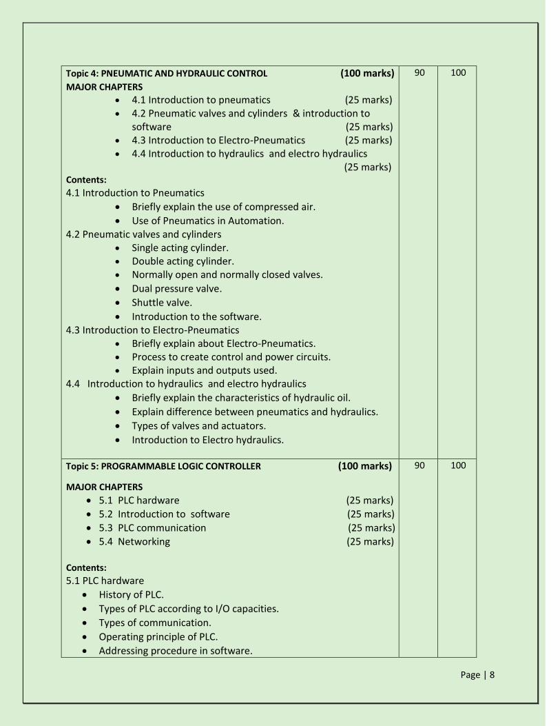
Topic 4: PNEUMATIC AND HYDRAULIC CONTROL (100 marks) MAJOR CHAPTERS
4.1 Introduction to pneumatics (25 marks)
4.2 Pneumatic valves and cylinders & introduction to software (25 marks)
4.3 Introduction to Electro-Pneumatics (25 marks) 4.4 Introduction to hydraulics and electro hydraulics
(25 marks) Contents:
4.1 Introduction to Pneumatics
Briefly explain the use of compressed air.
Use of Pneumatics in Automation. 4.2 Pneumatic valves and cylinders
Single acting cylinder. Double acting cylinder. Normally open and normally closed valves.
Dual pressure valve.
Shuttle valve.
Introduction to the software. 4.3 Introduction to Electro-Pneumatics
Briefly explain about Electro-Pneumatics. Process to create control and power circuits. Explain inputs and outputs used.
4.4 Introduction to hydraulics and electro hydraulics
Briefly explain the characteristics of hydraulic oil.
Explain difference between pneumatics and hydraulics.
Types of valves and actuators.
Introduction to Electro hydraulics.
90 100
Topic 5: PROGRAMMABLE LOGIC CONTROLLER (100 marks)
MAJOR CHAPTERS
5.1 PLC hardware (25 marks) 5.2 Introduction to software (25 marks) 5.3 PLC communication (25 marks) 5.4 Networking (25 marks)
Contents:
5.1 PLC hardware
History of PLC.
Types of PLC according to I/O capacities.
Types of communication.
Operating principle of PLC.
Addressing procedure in software.
90 100

Page | 9
5.2 Introduction to software
Creation of new project.
Process to complete hardware configuration and download PLC.
NO and NC programming.
Memory bit operations
Bit logic operations.
Timer operations.
Counter operations.
Analog process.
Function block.
Data block.
Variable table.
Function block diagram.
Statement list. 5.3 PLC communication
Profinet connection.
Profibus connection.
Multipoint interface (MPI) connection
Point to point (PPI) connection
Ethernet connection. 5.4 Networking
Single PC to multiple PLC communication
Multiple PC to multiple PLC communication.
Multiple PC to single PLC communication.
Single PLC to RIO communication.
Single PLC to multiple RIO communication.
Topic 6a: EMBEDDED SYSTEM (100 marks)
MAJOR CHAPTERS
6.1 Introduction (50 marks) 6.2 interfacing peripheral devices (50 marks)
Content 6.1 Introduction
Introduction to embedded system. Assembly and embedded c-programming
6.2 interfacing peripheral devices Addressing of 8051 PIC 18 and ARM7 using RIDE
PROTIUS MPLAB KEIL Interfacing of peripheral device
90 100
Page | 10
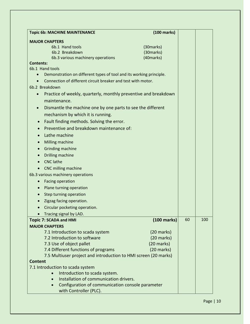
Topic 6b: MACHINE MAINTENANCE (100 marks)
MAJOR CHAPTERS 6b.1 Hand tools (30marks)
6b.2 Breakdown (30marks) 6b.3 various machinery operations (40marks)
Contents: 6b.1 Hand tools
Demonstration on different types of tool and its working principle.
Connection of different circuit breaker and test with motor.
6b.2 Breakdown
Practice of weekly, quarterly, monthly preventive and breakdown
maintenance.
Dismantle the machine one by one parts to see the different
mechanism by which it is running.
Fault finding methods. Solving the error.
Preventive and breakdown maintenance of:
Lathe machine
Milling machine
Grinding machine
Drilling machine
CNC lathe
CNC milling machine
6b.3 various machinery operations
Facing operation
Plane turning operation
Step turning operation
Zigzag facing operation.
Circular pocketing operation.
Tracing signal by LAD.
Topic 7: SCADA and HMI (100 marks)
MAJOR CHAPTERS
7.1 Introduction to scada system (20 marks)
7.2 Introduction to software (20 marks) 7.3 Use of object pallet (20 marks) 7.4 Different functions of programs (20 marks) 7.5 Multiuser project and introduction to HMI screen (20 marks)
Content 7.1 Introduction to scada system
Introduction to scada system. Installation of communication drivers. Configuration of communication console parameter
with Controller (PLC).
60 100

Page | 11
Configuration of communication console parameter
With MTU.
7.2 Introduction to software
Process to create single user project. Process to activate and deactivate a project. Process to copy a project. Explain graphics designer tools.
7.3 Use of object pallet Difference between standard object, windows object
and smart objects. Functions of standard objects. Functions of smart objects. Functions of windows objects.
7.4 Different functions of programs Multiscreen. Picture window. Window operations.
Internal tags usage. Analog control. Alarm logging. Tag logging.
7.5 Multiuser project and introduction to HMI screen Process to connect one system to another. Process to create multiuser project. Process to transfer wincc project from one system to
another. Explain the process to configure HMI screen.
Procedure to download programs to the HMI panel.
Topic 8: TIA Portal (100 marks)
8.1 Introduction to software (20 marks) 8.2 Bit logic operations (20 marks) 8.3 Timer and counter application (20 marks) 8.4 Analog application (20 marks) 8.5 PLC to PLC communication (20 marks)
content 8.1 Introduction to software
Introduction to software
Briefly explain the creation and downloading of function block, data block and variable table.
8.2 Bit logic operations
Negate assignment Set coil operation Reset coil operation
60 100
Page | 12
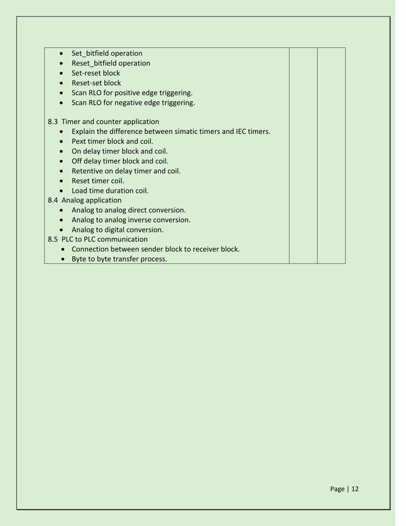
Set_bitfield operation Reset_bitfield operation Set-reset block Reset-set block Scan RLO for positive edge triggering. Scan RLO for negative edge triggering.
8.3 Timer and counter application
Explain the difference between simatic timers and IEC timers. Pext timer block and coil. On delay timer block and coil. Off delay timer block and coil. Retentive on delay timer and coil. Reset timer coil. Load time duration coil.
8.4 Analog application Analog to analog direct conversion. Analog to analog inverse conversion. Analog to digital conversion.
8.5 PLC to PLC communication Connection between sender block to receiver block. Byte to byte transfer process.

Page | 13
Topic 9: PCS7 (100 marks)
MAJOR CHAPTERS
9.1 Details on software (50 marks)
9.2 introduction to blocks. (50 marks) Content:
9.1 Details on software
Details of AS, OS and ES.
Single user project
Muti user project
Process object
CFC
SFS
Plant hierarchy setting
OS Compile
9.2 Introduction to blocks
Bit logic operands and application
And, Or, Not, x-or gates
Flip Flop (JK,RS,SR)
Converters
Move
Comparator
Timer
Counter
Interfacing with AS and ES
Motor block
Valve block
Interlock block
OS compiling
Alarm and Trend report design.
10 100

Page | 14
Topic 10: LAB VIEW (100 marks)
MAJOR CHAPTERS
10.1 Introduction to software and content (100 marks) Content:
10.1 Introduction to software and content Introduction.
Software open and types of data with arguments. Sub VI Case Structure. For loop and while loop Feedback node Shift register Flat sequence.
30 100
Topic 11: ROBOTICS (100 marks)
MAJOR CHAPTERS
11.1 Introduction (25 marks) 11.2 KUKA SIM PRO (25 marks) 11.2 Study about KUKA robot (50 marks) Content:
11.1 Introduction
Introduction to robotics and scope 11.2 KUKA SIM PRO
Study of KUKA SIM PRO software Simulation software Study of Angular Limits of all the KUKA KR 16 Robot Mastering industrial Robots KUKA KR 16
10.3 Study about KUKA robot Manipulation of KUKA KR 16 in axial motion and world motion.
Recording and Running of Robot programming. Writing Program using PTP. Linear Circular and Interpolation to do Automation.
30 100

Page | 15
Topic 12: AUTOCAD ELECTRICAL (100 marks)
MAJOR CHAPTERS
10.1 co-ordinate system (20 marks) 10.2 Software opening (20 marks) 10.3 Drafting features (20 marks) 10.4 Introduction to 3d and ECAD (40 marks) Content:
10.1 co-ordinate system Absolute co-ordinate system. Polar co-ordinate system. Incremental co-ordinate system.
10.2 Software opening
Introduction to the software.
Use of function keys and shortcut keys. Process to draw circle, rectangle, arc etc.
10.3 Drafting features
Process to create region. Explode Fillet Chamfer
Copy Move Offset Array Process to add text.
Hatch and gradient. By layer.
10.4 Introduction to 3d and ECAD Process to crate 3d diagram Introduction to E-cad. Overview about relay, contactors, timers and OLD. Process to add ladder, reverse ladder and add rung option. Drafting features like dash link line, align and scoot. Multiple wire bus. PLC positioning and schematic report generation.
30 100

Page | 16
Topic 13: COMMUNICATION SKILLS (100 marks)
MAJOR CHAPTERS
9.1 basics of communication (60 marks)
9.2 Introduction to soft skills. (20 marks)
9.3 Introduction to nonverbal communication (20 marks) Content:
9.1 basics of communication
Forms, types, purpose, theory, examples from daily schedules. 9.2 Introduction to soft skills.
Presentation Skills – elocution, debates, extempore, etc.
Newspaper reading
Introduction to Body Language – positive gestures, handshakes, eye
contact, smiles, styles of walking, hand movements, etc.
Activities on Listening Skill
Role Plays and Situation Handling
Etiquette and Manners – general and specific, greetings/salutations,
etc.
Personal and Professional Goal Setting.
9.3 Introduction to nonverbal communication
One- to-one interaction & group exercises.
Presentation of an effective cover letter, resume/curriculum vitae
Group Discussion
Personal Interview
Corporate Interface
10 100
Intellectual Skills:
1. Prepare one line diagrams without error.
2. Select proper material and procedures in circuit designing operation.
3. Use proper tools to rectify error in machines.
4. Design and develop logics in modern software.
5. Animate the real view in software.
Motor Skills:
1. Generate the program in distributed control system by using PCS-7 software.
2. Develop working drawing using Auto CAD.
3. Generate the program by using TIA Portal software to produce multi controller system.
Page | 17
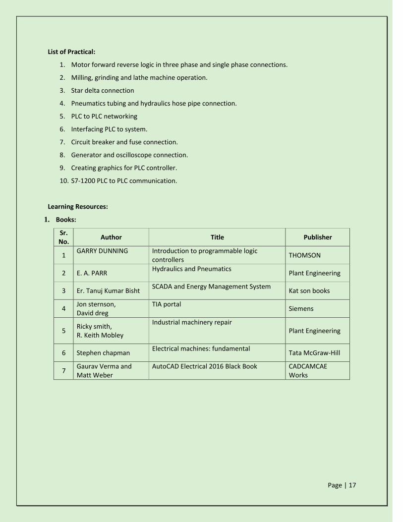
List of Practical:
1. Motor forward reverse logic in three phase and single phase connections.
2. Milling, grinding and lathe machine operation.
3. Star delta connection
4. Pneumatics tubing and hydraulics hose pipe connection.
5. PLC to PLC networking
6. Interfacing PLC to system.
7. Circuit breaker and fuse connection.
8. Generator and oscilloscope connection.
9. Creating graphics for PLC controller.
10. S7-1200 PLC to PLC communication.
Learning Resources:
1. Books:
Sr. No.
Author Title Publisher
1 GARRY DUNNING Introduction to programmable logic
controllers THOMSON
2 E. A. PARR Hydraulics and Pneumatics
Plant Engineering
3 Er. Tanuj Kumar Bisht SCADA and Energy Management System
Kat son books
4 Jon sternson, David dreg
TIA portal Siemens
5 Ricky smith, R. Keith Mobley
Industrial machinery repair Plant Engineering
6 Stephen chapman Electrical machines: fundamental
Tata McGraw-Hill
7 Gaurav Verma and Matt Weber
AutoCAD Electrical 2016 Black Book CADCAMCAE Works

Page | 18