Embed Size (px)
Citation preview

Massively Scaling the Metal Microscopic Damage Simulation onSunway TaihuLight Supercomputer
Shigang LiSKL Computer Architecture, Instituteof Computing Technology, Chinese
Academy of [email protected]
Baodong WuSKL Computer Architecture, Institute
of Computing Technology, CAS;University of Chinese Academy of
Yunquan ZhangSKL Computer Architecture, Instituteof Computing Technology, Chinese
Academy of [email protected]
Xianmeng WangUniversity of Science and Technology
Jianjiang LiUniversity of Science and Technology
Changjun HuUniversity of Science and Technology
Jue WangComputer Network Information
Center, [email protected]
Yangde FengComputer Network Information
Center, [email protected]
Ningming NieComputer Network Information
Center, [email protected]
ABSTRACTThe limitation of simulation scales leads to a gap between simula-tion results and physical phenomena. This paper reports our effortson increasing the scalability of metal material microscopic damagesimulation on the Sunway TaihuLight supercomputer. We use amultiscale modeling approach that couples Molecular Dynamics(MD) with Kinetic Monte Carlo (KMC). According to the charac-teristics of metal materials, we design a dedicated data structure torecord the neighbor atoms for MD, which significantly reduces thememory consumption. Data compaction and double buffer are usedto reduce the data transfer overhead between the main memory andthe local store. We propose an on-demand communication strategyfor KMC to remarkably reduce the communication overhead. Wesimulate 4 ∗ 1012 atoms on 6,656,000 master+slave cores using MDwith 85% parallel efficiency. Using the coupled MD-KMC approach,we simulate 3.2∗1010 atoms in 19.2 days temporal scale on 6,240,000master+slave cores with runtime of 8.6 hours.
CCS CONCEPTS•Computingmethodologies→Massively parallel algorithms;• Computer systems organization→ Multicore architectures;
KEYWORDSparallel scalability, microscopic damage simulation, Sunway Taihu-Light, Molecular Dynamics, Kinetic Monte Carlo
1 INTRODUCTIONMicroscopic damage in materials is difficult to observe by physi-cal experiments. Alternatively, software simulation is a promisingmethod to understand the evolution mechanism of the microscopicdamage. The existing simulation software in materials science, suchas Molecular Dynamics (MD) [7, 8, 22, 27] and Kinetic Monte Carlo(KMC) [14, 23, 31], has good performance in a specific temporal
and spatial range. However, the microstructure and damage evolu-tion process of materials have a much larger spatio-temporal scale.Thus, there is a big gap between simulation results and physicalphenomena due to the limitation of simulation scales.
Typically, the simulation scales are limited due to the followingtwo reasons: (1) Single model usually only performs well at a spe-cific narrow range. For example, MD commonly simulates millionsto billions of atoms at picoseconds to nanoseconds. In this paper, weuse a coupledMD-KMC approach to achieve both high temporal andspatial scales. (2) Large-scale simulation has a high computationalcomplexity and requires a great amount of computing resources. Al-though supercomputers are becoming more powerful, the existingsoftware lags behind because of the high effort of code porting andoptimization on new machines. We optimize our coupled MD-KMCcode on the Sunway TaihuLight supercomputer, and utilize its richcomputing resources to conduct large-scale microscopic damagesimulation.
In the last decade, the computing capability of supercomputershas been growing rapidly. The top one system in 2016, SunwayTaihuLight [6], possesses 93 PFlops sustained Linpack performance.Besides, due to the constrains caused by the heat dissipation andpower consumption issues, recent large systems come in the form ofheterogeneous systemswith both CPUs andmany-core accelerators,such as GPUs [20], Intel Xeon Phi [3], and Sunway many-coreaccelerator [6]. To achieve good performance, applications shouldefficiently utilize both CPUs and accelerators.
Our application simulates the microscopic damage for the metalmaterial composed of iron (Fe) atoms. Our application also sup-ports the simulation of different atoms, e.g., the alloy materials.To achieve this, more interpolation tables should be used to cal-culate the embedded-atom method (EAM) potential, as discussedin Section 2.1.2. The atoms are modeled in Body-Centered Cubic(BCC) structure, and EAM potential [4] is used as physical inter-action. We use MD to simulate the defect generation caused by

cascade collision, and use KMC to simulate the defect evolution andclustering. We aim at scaling the simulation with the increasing ofthe workload (larger temporal and spatial scale) and the availablehardware resources. However, there are several challenges: (1) thememory consumption linearly increases with the number of theatoms, which may run out of the system memory and limits thespatial scale; (2) communication overhead caused by ghost dataexchange and synchronization hinder the scalability with the in-creasing of computation nodes; (3) the small local store on the slavecore of Sunway many-core processor makes it difficult to utilizethe accelerator efficiently. We propose several methods, includinga dedicated data structure for metal materials, on-demand commu-nication, and data compaction, to overcome the above challenges.We simulate 4 ∗ 1012 atoms on 6,656,000 master+slave cores usingMD with 85% parallel efficiency (weak scaling). Strong scaling testsfor MD show that it simulates 3.2 ∗ 1010 atoms on 6,240,000 mas-ter+slave cores with 41.3% parallel efficiency. We simulate 3.2∗1010atoms in 19.2 days temporal scale on 6,240,000 master+slave coresusing the coupled MD-KMC approach, with runtime of 8.6 hours.
The key contributions of this paper are as follows:(1) We improve the previously proposed data structure, lattice
neighbor list [11], which significantly reduces the memoryconsumption while deals with the run-away atoms moreefficiently.
(2) We compact the interpolation table for force calculation,which remarkably reduces the data transfer overhead be-tween the main memory of CPU and the local store of slavecores.
(3) We propose an on-demand communication strategy for KMCto reduce the communication overhead.
(4) Experimental results show that our coupled MD-KMC ap-proach exhibits good scalability on the Sunway TaihuLightsupercomputer. The simulation results successfully revealthe vacancy cluster phenomenon.
In the next section, we discuss the coupled MD-KMC approachfor the microscopic damage simulation and the optimizations forincreasing the scalability on the heterogeneous parallel system.Sections 2.1 and 2.2 discuss MD and KMC, respectively. Experi-mental results and analysis on Sunway TaihuLight are presentedin Section 3. Section 4 discusses the related work, and Section 5concludes.
2 A COUPLED MD-KMC APPROACHWe use a coupled MD-KMC approach to simulate the microscopicdamage under the environment of irradiation for iron material. Theiron atoms are modeled in Body-Centered Cubic (BCC) structure.BCC has one lattice point in the center of the cube and eight cornerpoints. If a atom runs away from the lattice point, it forms a va-cancy at the lattice point. The side length of the cube is called latticeconstant. The BCC structure is shown in Figure 1. MD simulatesthe defect generation caused by cascade collision, and outputs thecoordinates of vacancy and the information of atoms. KMC sim-ulates the defect evolution and vacancies clustering. The coupledMD-KMC approach has been intensively studied in the field ofphysics [16, 24, 29]. This paper focuses on how to scale it up onsupercomputers.
Fe
Vacancy
Figure 1: The structure of body-centered cubic.
Embedded-Atom Method (EAM) potential is used as physicalinteraction between the atoms. Typically, EAM potential consistsof pair potential and embedding potential, as shown Equation (1),in which 𝑒 denotes pair potential, 𝐹 denotes embedding energy,and 𝜌 denotes the electron cloud density. For a specific atom, pairpotential 𝑒 and electron cloud density 𝜌 are the accumulated ef-fect of the neighbor atoms within the cutoff radius, as shown inEquation (2) and Equation (3). For both MD and KMC, the EAM po-tential calculation is the core computation part. MD uses the EAMpotential to calculate the forces of the atoms, and then updatesthe coordinates and the velocity of the atoms. KMC uses the EAMpotential to calculate the probability of the vacancy transition.
𝐸𝑡𝑜𝑡𝑎𝑙 =
𝑛∑𝑖=1
𝑒𝑖 +𝑛∑𝑖=1
𝐹 (𝜌𝑖 ) (1)
𝑒𝑖 =12∑𝑖≠𝑗
𝜙𝑖 𝑗 (𝑟𝑖 𝑗 ) (2)
𝜌𝑖 =∑𝑖≠𝑗
𝑓𝑖 𝑗 (𝑟𝑖 𝑗 ) (3)
To scale the application (both MD and KMC) across multiplecomputation nodes, we use the standard domain decomposition toequally partition the simulation box. Each computation node (i.e.,each process) is responsible for a subdomain. To calculate the stateof the atoms on the edge of the subdomain, the corresponding pro-cess has to access the data on the edge of the neighbor subdomains,which is commonly called ghost data. The ghost data should beupdated with the increasing of the time steps. Thus, each processshould communicate with the neighbor processes to exchange theghost data after each time step (or several time steps).
2.1 Molecular Dynamics2.1.1 Lattice neighbor list for the BCC structure. The simulation
is based on the short-range forces. Thus, only the atoms withina specific cutoff radius interact with the central atom. Two datastructures are commonly used to find the interaction atoms: neigh-bor list [22, 25] and linked cell [9, 19, 27]. For neighbor list, eachatom maintains a list to store all the neighbor atoms within a dis-tance which is equal to the cutoff radius plus a skin distance. Thus,the memory consumption of neighbor list is costly. The neighboratoms should be updated after several time steps. Linked cell dividesthe simulation box into cubic cells, whose edge length is equal tothe cutoff radius. Linked cell ensures that all interaction partnersfor any given atom are located either within the cell of itself orthe surrounding cells. Each cell maintains all the atoms within itand the pointers to the neighbor cells. Compared with neighbor
2

list, linked cell consumes less memory. However, it should updatethe atoms within each cell at each time step, which leads to highcomputational overhead.
0
1
2
3
4
5
6
7
8
9
10
11
12
13
14
15
16
17
18
19
20
21
22
23
24
ID Information Pointer
0 Atom info Null
1 Atom info Null
2 Atom info Null
3 Atom info Null
4 Atom info Null
...
cutoff radius
Figure 2: Lattice neighbor list for a 2-dimension simulationbox. The black circles represent the atoms.
We focus on the microscopic damage simulation of the metalmaterial with the BCC structure under the environment of irradi-ation. In this situation, most of the atoms stay very close to thelattice point and only a few atoms would break the constrain andrun away from the lattice point. Based on this physical feature, wedesign a dedicated data structure, called lattice neighbor list, tostore the atom information and record the neighbor atoms. We rankthe atoms in the order of their spatial distribution. The informationof the atoms, such as coordinates, velocity, force, and electron clouddensity, is sequentially stored in a array in the order of the atomsranks. An example with a 2-dimension simulation box is shownin Figure 2. Meanwhile, the neighbor atoms for a central atom arealso regularly distributed in a region determined by the cutoff ra-dius. Therefore, we can easily calculate the indexes of the neighboratoms in the array for a central atom. As shown in Figure 2, theneighbor atoms of 𝑎𝑡𝑜𝑚10 are 𝑎𝑡𝑜𝑚9, 𝑎𝑡𝑜𝑚11, 𝑎𝑡𝑜𝑚16, and 𝑎𝑡𝑜𝑚18.For each central atom, the offsets of the neighbor atoms relativeto the central atom are the same. This means the indexes of theneighbor atoms for each central atom can be calculated in the sameway.
0
1
2
3
4
5
6
7
8
9
10
11
12
13
14
15
16
17
18
19
20
21
22
23
24
VacancyID Information Pointer
-1 Vacancy position Null
0 Atom info Null
2 Atom info Null
3 Atom info Pointer
4 Atom info Null
...
1 Atom info Null
Figure 3: Data structures for run-away atoms. The black cir-cles represent the atoms.
Next, we discuss how to deal with the atoms which run awayfrom the lattice point in the lattice neighbor list structure. Whenan atom runs away from the lattice point, it generates a vacancy, asshown in Figure 3. We allocate another memory space to store the
information of the run-away atom, and leave the original entry inthe array to record the coordinates of the vacancy (ID is modifiedto a negative number to indicate this is a vacancy). If a run-awayatom moves to a vacancy at the lattice point, the information of thevacancy in the array is overlapped by the run-away atom. Other-wise, the information of the run-away atom is linked to the entry ofthe nearest lattice point to facilitate further processing. In Figure 3,𝑎𝑡𝑜𝑚1 runs away and its information is linked to the entry of thenearest regularly distributed neighbor 𝑎𝑡𝑜𝑚3. When a central atom(regularly distributed) finds its neighbor atoms within the cutoffradius, it not only checks the regularly distributed atoms, but alsochecks the run-away atoms linked to the lattice points. When arun-away atom finds its neighbor atoms within the cutoff radius,it checks the same neighbor atoms as the nearest lattice point it islinked to. Here, the extra overhead is the calculation of the nearestlattice point that the run-away atom is linked to. In our simulation,the number of the run-away atoms is only several millionth ofthe number of all the atoms. Therefore, the extra overhead can beignored.
When exchanging the ghost data, the lattice points (either anatom or a vacancy) in the ghost region is packed (unpacked) and sent(received) according to the indexes in the array. For the ghost data atthe lattice points, the communication pattern is static, which can bereused at each time step. For the run-away atoms, if they move intothe subdomain or the ghost region of the neighbor processes, wepack their information and send it to the corresponding neighborprocesses.
While the authors of [11] have discussed the lattice neighborlist structure, this paper further improves the structure by storingthe run-away atoms using linked lists rather than an array. Thebenefit of using linked lists is two-fold. Firstly, the number of run-away atoms may exceed the size of the array. The linked list canovercome this drawback by having a dynamic size. Secondly, whenusing the array, the overhead of finding neighbors between therun-away atoms is 𝑂 (𝑁 2) (where 𝑁 is the number the run-awayatoms), since the relative position information between the run-away atoms is lost. On the contrary, the linked lists can reducethis overhead to 𝑂 (𝑁 ) since the run-away atoms are linked tothe nearest lattice point. Compared with the traditional neighborlist and linked cell structures, our lattice neighbor list structuresignificantly reduces the memory and computation cost, since itdoes not have to maintain the extra structures and finds most ofthe neighbor atoms by static indexes. Compared with LAMMPS(using neighbor list) [22] and IMD (using linked cell) [27], ourlattice neighbor list structure reduces the memory consumptionsignificantly, and thus can simulate a larger number of atoms.
2.1.2 Reduce the data transfer cost between main memory andlocal store. Nextwe discuss how to efficiently use slave cores on Sun-way many-core processor to accelerate the calculation of EAM po-tential. First, we briefly introduce the Sunway many-core architec-ture [6]. As shown in Figure 4, it consists of four core groups (CGs).Each CG includes one management processing element (MPE), onecomputing processing element (CPE) cluster organized as an 8x8mesh, and one memory controller (MC). For convenience, we callMPE as master core and call CPE as slave core in this paper. Eachslave core has 64 KB local store, which can be configured as either
3

Network-on-Chip
MPE
PPUMC
Main Memeory
CG2
System Interface
CPE cluster(8x8)
MPE
PPUMC
Main Memeory
CG3
CPE cluster(8x8)
MPE
PPUMC
Main Memeory
CG0
CPE cluster(8x8)
MPE
PPUMC
Main Memeory
CG1
CPE cluster(8x8)
Figure 4: Sunway many-core architecture.
a user-controlled buffer or a software-emulated cache that achievesautomatic data caching. Here we use it as a user-controlled buffersince it generally obtains better performance [6]. These four CGsare connected via the network on chip. The processor connects toother outside devices through a system interface (SI). To acceleratethe computation using slave cores, we use one process on eachmaster core, and each process launches 64 threads (running on 64slave cores) using the 𝐴𝑡ℎ𝑟𝑒𝑎𝑑 multithreading library supportedby Sunway TaihuLight. The subdomain of each process is furtherequally partitioned into slabs, and each thread is responsible forone slab.
S[3]
S[4]
...
Compacted interpolation table
S[1]
S[0]
X = 7
Y =
50
00
X = 1
Y =
50
00
L[5,2]...
...
...
...
...
...
...
Traditional interpolation table
Interpolation formula: L[5,2] = ( S[0] - S[4] + 8*(S[3] - S[1]) )/12
Figure 5: Interpolation table compaction (using pair poten-tial table as an example). L[5,2] is calculated using S[0], S[1],S[3], and S[4] in the compacted table.
To calculate the EAM potential, we use the cubic spline inter-polation method, which is also used in other MD software, such
as LAMMPS [22] and CoMD [8]. Typically, three interpolation ta-bles are used for EAM potential computation, including electroncloud density table, pair potential table, and embedding potentialtable. During the computation, these three tables will be accessedsequentially. Taking electron cloud density table as an example,table querying would return the value of the electron cloud den-sity according to the distance between two atoms. Each traditionalinterpolation table (used in LAMMPS and CoMD) is a 5000*7 2Darray, where "5000" is the maximum distance between two atoms,as shown in Figure 5. The interpolating function consists of 5000segments (for different distances) of cubic functions. The 2D array isthe coefficient matrix for the cubic functions, in which the columns3-6 are the coefficients of a cubic function and the columns 0-2 arethe coefficients of its derivative function. Thus, there are total 7columns for the 2D array. The size of each traditional interpolationtable is about 273 KB, which exceeds the size of local store (64 KB)on each slave core. Thus, traditional interpolation table can notbe loaded in the local store at one time. Each slave core has to fre-quently uses DMA get operations (3 times for each neighbor atomat each time step) to transfer the table entries from main memoryto local store, which severely damages the overall performance. Tosolve this problem, we use a compacted interpolation table, ofwhich size is only 39 KB (1/7 of the traditional table). The compactedinterpolation table contains the values of 5000 sampling points (i.e.the values of pair potentials between different distances). We loadthe whole compacted table into the local store at one time. Then,all the values in the traditional table can be calculated on the flyusing the compacted table and a specific interpolation formula, asshown in Figure 5. Although this will bring extra computationaloverhead, it can be amortized by significantly reducing the datatransfer overhead.
For alloy materials, more interpolation tables are used, sincethere are different kinds of interaction for different atomic pairs.Taking the Fe-Cu alloy as an example, there are three kinds ofelectron cloud density tables, for the atomic pairs of Fe-Fe, Cu-Cu,and Fe-Cu, respectively. The total size of these three compactedtables will exceed the size of local store. Thus, we only load thecompacted table for the element with the highest content in thelocal store, since it would be the most frequently used, and leave theother tables in the main memory. Another method is to distribute allthe tables to the local stores of neighbor slave cores, and use registercommunication supported by Sunway many-core architecture totransfer data between the local stores. However, since which datain the tables should be transferred cannot be known before runtime,it is very difficult to describe these irregular communications usingregister communication.
get(1)
compute(1)
get(2) put(1)
buffers(1)
compute(2)
get(1)
compute(1)
input buffers(2)output input output
wait wait wait
put(2)...
Figure 6: Double buffer for overlapping atoms informationtransfer with computation.
4
Since our simulation has large spatial scale, the atoms informa-tion of one slab cannot be loaded into the local store at one timeeither. Thus, each slab is further partitioned into blocks, and eachslave core processes the blocks one by one. For each block, theslave core would get the atoms information into local store, and putback the output results (the updated position and velocity) to themain memory at each time step. To reduce the overhead of atomsinformation transfer, we propose two methods: (1) Data reuse. Forthe atoms information of one block, the data on the edge of theblock is actually the ghost data for the next block. Thus, we keepthe ghost data in the local store and reuse it in the next block, whichreduces the overhead of data transfer to some extent. (2) Doublebuffer. Each slave core allocates two buffers on local store for theinput and output data of each block. While carrying out DMA putor get on one buffer, it computes the potential or force on the otherbuffer, and vice versa. In this way, we overlap atoms informationtransfer with computation, as shown in Figure 6.
2.2 Kinetic Monte CarloSince the time step of MD is very short (typically at femtosecondscale), the temporal scale of MD simulation is generally limited tonanoseconds or less [32]. Kinetic Monte Carlo (KMC) is a stochas-tic method, which simulates the time evolution of some processesoccurring with known transition rates among states. In our applica-tion, to couple MD with KMC, the temporal scale of MD should atleast be 50 picoseconds. MD outputs the coordinates of vacanciesand atoms, which are used as the input of KMC. KMC continuesto simulate the vacancy clustering and evolution at a much largertemporal scale.
There are several different KMC approaches, such as atomisticKMC (AKMC) [1] and object KMC (OKMC) [15]. We choose to useAKMC to reveal the defect evolution for metal material. AKMC usesan on-lattice approximation method to map each atom or vacancyto a lattice point, and the atoms and vacancies are uniformly namedas ’sites’. It describes the vacancy transitions (or events) as theposition exchanges between atoms and vacancies. For the BCCstructure in a 3D simulation box, as shown in Figure 1, there areeight possible events for a vacancy (since it may exchange with oneof its eight nearest neighbors). The transition rate 𝑘𝑖 𝑗 is calculatedas
𝑘𝑖 𝑗 = 𝑣 exp(−Δ𝐸𝑖 𝑗/𝑘𝐵𝑇 ) (4)where 𝑣 is the pre-exponential factor, Δ𝐸𝑖 𝑗 is the migration energy(calculated by EAM potential) from the state 𝑖 to the state 𝑗 , 𝑘𝐵 isBoltzmann constant, and 𝑇 is the temperature. We use the interpo-lation method to calculate the EAM potential, which is the same asMD and can be accelerated by the slave cores.
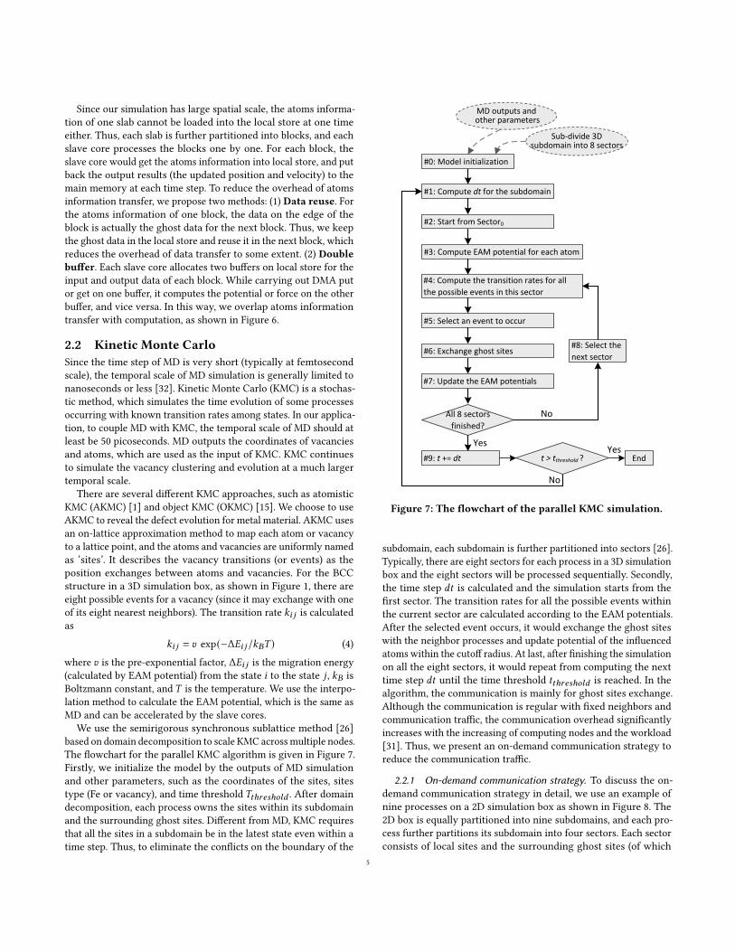
We use the semirigorous synchronous sublattice method [26]based on domain decomposition to scale KMC acrossmultiple nodes.The flowchart for the parallel KMC algorithm is given in Figure 7.Firstly, we initialize the model by the outputs of MD simulationand other parameters, such as the coordinates of the sites, sitestype (Fe or vacancy), and time threshold 𝑇𝑡ℎ𝑟𝑒𝑠ℎ𝑜𝑙𝑑 . After domaindecomposition, each process owns the sites within its subdomainand the surrounding ghost sites. Different from MD, KMC requiresthat all the sites in a subdomain be in the latest state even within atime step. Thus, to eliminate the conflicts on the boundary of the
#1: Compute dt for the subdomain
Sub-divide 3D subdomain into 8 sectors
MD outputs andother parameters
All 8 sectors
finished?
Yes
No
Yes
#0: Model initialization
#2: Start from Sector0
#4: Compute the transition rates for all
the possible events in this sector
#3: Compute EAM potential for each atom
#5: Select an event to occur
#6: Exchange ghost sites
#7: Update the EAM potentials
End
#8: Select the
next sector
t > tthreshold ?#9: t += dt
No
Figure 7: The flowchart of the parallel KMC simulation.
subdomain, each subdomain is further partitioned into sectors [26].Typically, there are eight sectors for each process in a 3D simulationbox and the eight sectors will be processed sequentially. Secondly,the time step 𝑑𝑡 is calculated and the simulation starts from thefirst sector. The transition rates for all the possible events withinthe current sector are calculated according to the EAM potentials.After the selected event occurs, it would exchange the ghost siteswith the neighbor processes and update potential of the influencedatoms within the cutoff radius. At last, after finishing the simulationon all the eight sectors, it would repeat from computing the nexttime step 𝑑𝑡 until the time threshold 𝑡𝑡ℎ𝑟𝑒𝑠ℎ𝑜𝑙𝑑 is reached. In thealgorithm, the communication is mainly for ghost sites exchange.Although the communication is regular with fixed neighbors andcommunication traffic, the communication overhead significantlyincreases with the increasing of computing nodes and the workload[31]. Thus, we present an on-demand communication strategy toreduce the communication traffic.
2.2.1 On-demand communication strategy. To discuss the on-demand communication strategy in detail, we use an example ofnine processes on a 2D simulation box as shown in Figure 8. The2D box is equally partitioned into nine subdomains, and each pro-cess further partitions its subdomain into four sectors. Each sectorconsists of local sites and the surrounding ghost sites (of which
5

P0 P1 P2
P3 P4 P5
P6 P7 P8
(a) 2d domain partition for 9processors
P0 P1 P2
P3 P5
P6 P7 P8
recv recv
recv send
send
P4
send
(b) Get the latest ghost sites fromneighbor processes
P0 P1 P2
P3 P5
sendsend
recv
recvrecv
send
P6 P7 P8
P4
(c) Put the ghost sites back to theneighbor processes
B
CD
P0 P1 P2
P3
P4P5
P6 P7 P8
send send
send
An event occurred
A
E F
(d) On-demand communication
Figure 8: The traditional communication pattern of KMC and the on-demand communication method.
width is determined by the cutoff radius). As shown in Figure 8(a),the solid lines represent the boundaries of the subdomains, thedotted lines represent the boundaries of the local sites of the sec-tors, and the shading region represents the ghost sites for a sector.Before processing a sector, each process has to get partial ghostsites (except those in the local subdomain) from the subdomains ofits neighbor processes, as shown in Figure 8(b). After finishing thesimulation of the current sector, each process has to put the ghostsites back to its neighbor processes, as shown in Figure 8(c). Thephilosophy of the two-time communication for each sector is tokeep the sites in the subdomain and its ghost sites always in thelatest state. This two-time communication pattern is widely usedin the KMC software, such as SPPARKS [23] and KMCLib [14]. Theneighbor processes and the send/receive buffers are determined atthe initialization phase, and keep static as the simulation moves on.All the sites in the ghost region have to be transferred regardlessof whether all the sites are updated or not. This causes a lot ofredundant communication, since generally only a very small partof sites in the ghost region are affected when an event occurs. Thecommunication redundancy is more expensive as the spatial scaleof the simulation getting larger.
To eliminate the communication redundancy, we present anon-demand communication strategy. It changes the traditionalstatic communication pattern to a dynamic communication pattern,namely the sites to be transferred and the neighbor processes aredetermined at runtime according to the state of the simulation sys-tem. When a vacancy transition (an event) occurs, it only affectsthe potential of atoms within the cutoff radius and the other siteskeep steady. To keep the sites in the subdomain and the ghost sitesalways in the latest state, we only have to transfer the affected sitesto the corresponding neighbor processes after the simulation of asector within a time step is finished. As illustrated in Figure 8(d),after the top-left sector of 𝑃4 is processed, it checks whether thesites in regions 𝐴, 𝐵, and 𝐶 are affected and puts the influencedsites into the sending queue. Taking region 𝐴 as an example, a sitein region 𝐴 is either a ghost site or a local site from the perspectiveof 𝑃4’ three neighbor processes (𝑃0, 𝑃1, and 𝑃3). Thus, if any site inregion 𝐴 is affected by the events, 𝑃4 would send it to 𝑃3, 𝑃0, and𝑃1. Similar acts are carried out for regions 𝐵 and 𝐶 . Meanwhile, 𝑃4receives data from the neighbor processes and unpacks the datainto either region 𝐷 , 𝐸, or 𝐹 to update the sites. In this way, only
the affected sites are transferred. Considering the vacancy concen-tration is very low in our application, the communication trafficis reduced significantly compared with the traditional communi-cation pattern. The on-demand communication strategy can beimplemented using MPI [17] two-sided communication interfaces,and both sender and receiver have to know all the informationabout the message. Since the source, the tag, and the size of the mes-sages are determined at runtime, the receiver does not know thisinformation before receiving the messages. Thus, the receiver hasto use MPI_Probe to query the information beforehand, and launchMPI_Recv afterwards to receive the actual data. However, sincethere is a match between the sender and the receiver, the senderhas to send a zero-size message to the receiver even there is noupdate in the ghost sites. Alternatively, we can use MPI one-sidedcommunication interfaces, by which only one side is involved inthe communication, to eliminate these zero-size messages. Firstly,each process opens a globally-shared window on the subdomain.Secondly, each process puts the updates in the ghost sites to itsneighbor processes. Thirdly, a global synchronization is carried outto guarantee the completion of the communications.
3 EVALUATIONOur experiments are conducted on the Sunway TaihuLight su-percomputer. The Sunway TaihuLight has total 40,960 computingnodes. The architecture of the computing node has been introducedin Section 2.1.2. For a core group, there is total 8 GB DDR3 mem-ory shared by a master core and 64 slave cores. Both master andslave cores work at 1.45GHz and support 256-bit vector instructions.Each master core has a 32 KB L1 cache and a 256 KB L2 cache, andeach slave core has a 64 KB local store. The software environmentof the system includes the customized 64-bit Linux kernel, andSunway compiler version 5.4 supporting C/C++, Fortran, OpenMP,and OpenACC. The 𝐴𝑡ℎ𝑟𝑒𝑎𝑑 multithreading library is provided toprogram on slave cores, and MPI library is provided for inter-nodecommunication. In the experiments, we use the microscopic dam-age simulation for the Fe metal material at 600K temperature underthe environment of irradiation. We demonstrate our application,implemented as the coupled MD-KMC model, achieves good per-formance and scalability on the Sunway TaihuLight supercomputer.It is unfair to compare the performance of our solution with theexisting software (such as LAMMPS and SPPARKS) directly. Thereasons include : (1) The existing software is not optimized for
6

Sunway architecture. (2) Our KMC implementation supports EAMpotential and scales up to 100,000 processes; on the contrary, theexisting parallel scalable software, like SPPARKS, does not supportEAM potential.
0
50
100
150
200
250
300
350
65 130 260 520 1040
Tota
l ru
nti
me
(sec
on
d)
Number of cores (master+slave cores)
TraditionalTable
CompactedTable
CompactedTable + DataReuse
CompactedTable + DataReuse + DoubleBuffer
Figure 9: Performance comparisons for the optimizationsof MD with 2 ∗ 107 atoms on Sunway many-core machines.
0%
20%
40%
60%
80%
100%
1
2
4
8
16
32
64
Para
llel
Effi
cien
cy
Spee
du
p
Number of cores (MPEs + CPEs)
Ideal SpeedupMDParallel Efficiency
Figure 10: Strong scaling of MD with 3.2 ∗ 1010 atoms usingboth master and slave cores.
0
50
100
150
200
250
300
350
400
450
Tota
l ru
nti
me
(sec
on
d)
Number of cores (master+slave cores)
Computation time
Communication time 80.1%
86.7%95.1% 90.7% 88.4% 85.0%
Figure 11: Weak scaling of MD using both master and slavecores, 3.9 ∗ 107 atoms per core group. Parallel efficiency isannotated on the top of the bar.
Firstly, we evaluate the optimization methods for reducing thedata transfer cost between the main memory and the local store
discussed in Section 2.1.2. We test the MD simulation with 2 ∗ 107atoms using different numbers of cores as shown in Figure 9. Com-pared with the traditional interpolation tables, the compacted tablesimprove the performance by 54.7% on average in geometric mean.This is because using the compacted table significantly reduces thenumber of DMA operations. Ghost data reuse further improves theperformance by 4% on average. However, double buffer does notbring obvious performance improvement, since there is not enoughcomputation to overlap the data transfer.
Figure 10 shows the strong scaling test for our optimized MDsimulation with 3.2 ∗ 1010 atoms. For MD, the master cores areresponsible for inter-node communication and the slave cores areresponsible for the EAM computation. We can see that the parallelefficiency gradually decreases as the increasing of the computingresources, which is caused by the communication overhead. Scalingfrom 97, 500 cores to 6, 240, 000 cores, we achieve 26.4-fold speedup(41.3% parallel efficiency). Figure 11 shows the weak scaling test forour optimized MD simulation. As we increase the number of coresfrom 104, 000 (including 1, 600 master cores and 1, 024, 000 slavecores) to 6, 656, 000 (including 102, 400 master cores and 6, 553, 600slave cores), the problem size increases from 6.25 ∗ 1010 atomsto 4.0 ∗ 1012 atoms to keep the workload per core fixed. Our MDcode scales up to 6.656 million cores with total 4.0 ∗ 1012 atomsby a 85% parallel efficiency. Using the traditional data structures(such as neighbor list), we only simulate about 8.0 ∗ 1011 atoms on6.656 million cores. The lower memory consumption of our latticeneighbor list structure contributes to a much larger spatial scale ofMD. We can see that the computation time remains almost constanton different numbers of cores. However, the communication timefor larger number of cores is a little higher, which is caused by thecommunication contention. The communication time on 208, 000cores is a little higher than others, which is probably caused by theprocesses topology mapping. Overall, our MD code exhibits goodstrong and weak scalability.
0
100
200
300
400
16 32 64 128 256 512 1024
Communication volume (M
B)
Number of cores (only master cores)
Traditional ghost data exchange
On‐demond communication
Figure 12: Communication volume comparison for KMCwith 1.6 ∗ 107 sites using only master cores, vacancy concen-tration is 4.5 ∗ 10−5.
Figure 12 presents the communication volume comparison be-tween the on-demand communication strategy for KMC and thetraditional ghost data exchange method (used in SPPARKS [23] andKMCLib [14]). The experiments are conducted on different number
7

0
1
2
3
4
5
6
7
16 32 64 128 256 512 1024
Communication tim
e (second)
Number of cores (only master cores)
Traditional ghost data exchange
On‐demond communication
Figure 13: Communication time comparison for KMC with1.6∗107 sites using onlymaster cores, vacancy concentrationis 4.5 ∗ 10−5.
0%
20%
40%
60%
80%
100%
120%
1
2
4
8
16
32
64
Para
llel
effi
cien
cy
Spee
du
p
Number of cores (only master cores)
Ideal speedupKMCParallel efficiency
Figure 14: Strong scaling of KMC with 3.2 ∗ 1010 sites usingonly master cores, vacancy concentration is 4.5 ∗ 10−5.
0
50
100
150
200
250
300
350
400
450
Tota
l ru
nti
me
(sec
on
d)
Number of cores (only master cores)
Computation time
Communication time
97.2%88.1% 86.1% 85.2%
79.9%74.0%
Figure 15: Weak scaling of KMC using only master cores,107 sites per core, vacancy concentration is 2 ∗ 10−6. Parallelefficiency is annotated on the top of the bar.
of cores (only master cores are used). The on-demand communi-cation strategy reduces the communication volume to 2.6% of thetraditional method on average. This is because the vacancy con-centration is very low and only a few sites in the ghost region areupdated after each time step. Figure 13 presents the communicationtime comparison between the on-demand communication strat-egy and the traditional ghost data exchange method. Compared
0
100
200
300
400
500
600
97,500 390,000 1,560,000 6,240,000
Tota
l ru
nti
me
(min
ute
)
Number of cores (master+slave cores)
98.9%
77.4% 75.7%
Figure 16: Weak scaling of the coupled MD-KMC approachusing both master and slave cores, 3.3 ∗ 105 atoms per coregroup. Parallel efficiency is annotated on the top of the bar.
with the traditional method, the on-demand communication strat-egy obtains 21x speedup on average in terms of communicationtime. Figure 14 presents the strong scaling test for KMC, in whichonly master cores are used. The baseline runs on 1, 500 cores with3.2 ∗ 1010 sites. Our KMC algorithm exhibits 18.5-fold speedup on48, 000 cores, indicating 58.2% parallel efficiency in strong scaling.The super-linear speedup from 3, 000 to 12, 000 cores is due to thebenefit of L2 cache on the master cores, which can store the entiredataset. However, with the number of cores increasing, the com-munication cost becomes the major limitation. Figure 15 shows theweak scaling test for KMC in which only master cores are used. Wekeep 107 sites per core as the number of cores increases from 1, 600to 102, 400. We observe that the computation time remains almostconstant while the communication time increases gradually. Theincreased communication time is due to the collective operationsused for time synchronization. Our KMC code scales up to 102, 400cores with 74% parallel efficiency. Our KMC code exhibits goodstrong and weak scalability.
We also present the weak scaling results for the coupled MD-KMCmodel in Figure 16. The number of cores increases from 97, 500to 6, 240, 000 while the number of atoms increases from 5.0 ∗ 108to 3.2 ∗ 1010. The results show that our coupled MD-KMC modelachieves good weak scalability, and attains 75.7% parallel efficiencyon 6, 240, 000 cores.
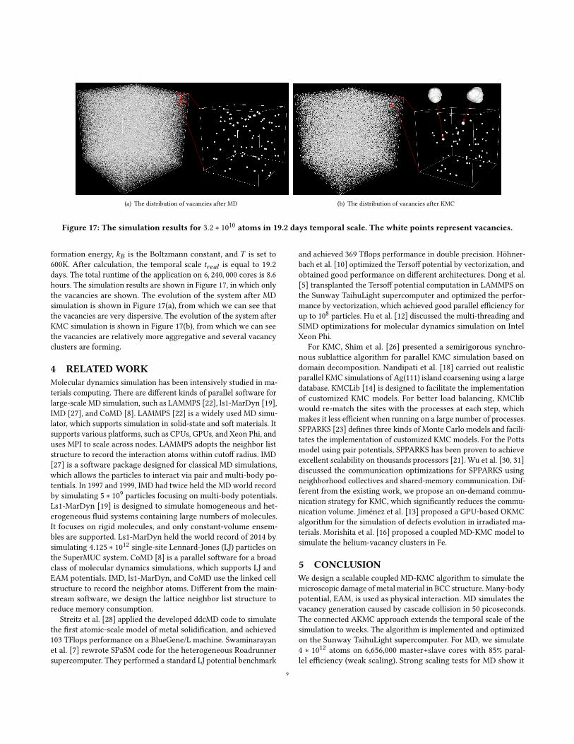
Furthermore, in order to demonstrate the ability of the coupledMD-KMC model to simulate at large spatio-temporal scale, we con-duct a simulation of microscopic damage evolution in Fe materialwith 3.2 ∗ 1010 atoms on 6, 240, 000 cores. The lattice constant isset to 2.855. MD simulates the defect generation caused by cascadecollision in the temporal scale of 50 picoseconds (time step is setto 1 femtosecond), and outputs the coordinates of vacancy andthe information of atoms. KMC continues to simulate the vacancyclustering and evolution in the temporal scale of days. The tempo-ral scale (real time) of KMC simulation can be calculated by theformula 𝑡𝑟𝑒𝑎𝑙 = 𝑡𝑡ℎ𝑟𝑒𝑠ℎ𝑜𝑙𝑑 𝐶
𝑀𝐶𝑣 /𝐶𝑟𝑒𝑎𝑙𝑣 [2]. Here, 𝑡𝑡ℎ𝑟𝑒𝑠ℎ𝑜𝑙𝑑 is the
threshold for the time steps, 𝐶𝑀𝐶𝑣 is the vacancy concentration in
the simulation box, and 𝐶𝑟𝑒𝑎𝑙𝑣 is the real vacancy concentration inthe experiment. 𝑡𝑡ℎ𝑟𝑒𝑠ℎ𝑜𝑙𝑑 is set to 0.0002.𝐶𝑀𝐶
𝑣 is 0.000002, which iseasily obtained by calculating the percentage of vacancies in atoms.𝐶𝑟𝑒𝑎𝑙𝑣 is obtained by 𝐶𝑟𝑒𝑎𝑙𝑣 = 𝑒𝑥𝑝 (−𝐸+𝑣 /𝐾𝐵 𝑇 ), where 𝐸+𝑣 is vacancy
8
(a) The distribution of vacancies after MD (b) The distribution of vacancies after KMC
Figure 17: The simulation results for 3.2 ∗ 1010 atoms in 19.2 days temporal scale. The white points represent vacancies.
formation energy, 𝑘𝐵 is the Boltzmann constant, and 𝑇 is set to600K. After calculation, the temporal scale 𝑡𝑟𝑒𝑎𝑙 is equal to 19.2days. The total runtime of the application on 6, 240, 000 cores is 8.6hours. The simulation results are shown in Figure 17, in which onlythe vacancies are shown. The evolution of the system after MDsimulation is shown in Figure 17(a), from which we can see thatthe vacancies are very dispersive. The evolution of the system afterKMC simulation is shown in Figure 17(b), from which we can seethe vacancies are relatively more aggregative and several vacancyclusters are forming.
4 RELATEDWORKMolecular dynamics simulation has been intensively studied in ma-terials computing. There are different kinds of parallel software forlarge-scale MD simulation, such as LAMMPS [22], ls1-MarDyn [19],IMD [27], and CoMD [8]. LAMMPS [22] is a widely used MD simu-lator, which supports simulation in solid-state and soft materials. Itsupports various platforms, such as CPUs, GPUs, and Xeon Phi, anduses MPI to scale across nodes. LAMMPS adopts the neighbor liststructure to record the interaction atoms within cutoff radius. IMD[27] is a software package designed for classical MD simulations,which allows the particles to interact via pair and multi-body po-tentials. In 1997 and 1999, IMD had twice held the MD world recordby simulating 5 ∗ 109 particles focusing on multi-body potentials.Ls1-MarDyn [19] is designed to simulate homogeneous and het-erogeneous fluid systems containing large numbers of molecules.It focuses on rigid molecules, and only constant-volume ensem-bles are supported. Ls1-MarDyn held the world record of 2014 bysimulating 4.125 ∗ 1012 single-site Lennard-Jones (LJ) particles onthe SuperMUC system. CoMD [8] is a parallel software for a broadclass of molecular dynamics simulations, which supports LJ andEAM potentials. IMD, ls1-MarDyn, and CoMD use the linked cellstructure to record the neighbor atoms. Different from the main-stream software, we design the lattice neighbor list structure toreduce memory consumption.
Streitz et al. [28] applied the developed ddcMD code to simulatethe first atomic-scale model of metal solidification, and achieved103 TFlops performance on a BlueGene/L machine. Swaminarayanet al. [7] rewrote SPaSM code for the heterogeneous Roadrunnersupercomputer. They performed a standard LJ potential benchmark
and achieved 369 Tflops performance in double precision. Höhner-bach et al. [10] optimized the Tersoff potential by vectorization, andobtained good performance on different architectures. Dong et al.[5] transplanted the Tersoff potential computation in LAMMPS onthe Sunway TaihuLight supercomputer and optimized the perfor-mance by vectorization, which achieved good parallel efficiency forup to 108 particles. Hu et al. [12] discussed the multi-threading andSIMD optimizations for molecular dynamics simulation on IntelXeon Phi.
For KMC, Shim et al. [26] presented a semirigorous synchro-nous sublattice algorithm for parallel KMC simulation based ondomain decomposition. Nandipati et al. [18] carried out realisticparallel KMC simulations of Ag(111) island coarsening using a largedatabase. KMCLib [14] is designed to facilitate the implementationof customized KMC models. For better load balancing, KMClibwould re-match the sites with the processes at each step, whichmakes it less efficient when running on a large number of processes.SPPARKS [23] defines three kinds of Monte Carlo models and facili-tates the implementation of customized KMC models. For the Pottsmodel using pair potentials, SPPARKS has been proven to achieveexcellent scalability on thousands processors [21]. Wu et al. [30, 31]discussed the communication optimizations for SPPARKS usingneighborhood collectives and shared-memory communication. Dif-ferent from the existing work, we propose an on-demand commu-nication strategy for KMC, which significantly reduces the commu-nication volume. Jiménez et al. [13] proposed a GPU-based OKMCalgorithm for the simulation of defects evolution in irradiated ma-terials. Morishita et al. [16] proposed a coupled MD-KMC model tosimulate the helium-vacancy clusters in Fe.
5 CONCLUSIONWe design a scalable coupled MD-KMC algorithm to simulate themicroscopic damage of metal material in BCC structure. Many-bodypotential, EAM, is used as physical interaction. MD simulates thevacancy generation caused by cascade collision in 50 picoseconds.The connected AKMC approach extends the temporal scale of thesimulation to weeks. The algorithm is implemented and optimizedon the Sunway TaihuLight supercomputer. For MD, we simulate4 ∗ 1012 atoms on 6,656,000 master+slave cores with 85% paral-lel efficiency (weak scaling). Strong scaling tests for MD show it
9
simulates 3.2 ∗ 1010 atoms on 6,240,000 master+slave cores with41.3% parallel efficiency. Using the coupled MD-KMC approach, wesimulate 3.2 ∗ 1010 atoms in 19.2 days temporal scale on 6,240,000master+slave cores with runtime of 8.6 hours. The simulation re-sults successfully reveal the vacancy cluster phenomenon.
Although the algorithm is implemented on the Sunway Taihu-Light supercomputer, our optimization methods are not hardware-specific. The proposed lattice neighbor list structure for MD pro-vides a valuable reference for metal materials simulations if theirspatial scale is limited by thememory consumption. The on-demandcommunication strategy for KMC are also useful on other big ma-chines if its communication overhead hinders the scalability withthe increasing of the computation nodes. Potential table compaction,ghost data reuse, and double buffer strategies would contribute toperformance improvement on heterogeneous architectures wherethe data transfer overhead between main memory and local storeis the bottleneck.
MD and KMC are typically considered as computation-intensive.However, their computation features, such as potential computationbased on interpolation table and frequent global synchronization,make it not easy to scale up even on the state-of-the-art super-computer. Although our software optimizations have alleviated theabove problems to some extent, we also come up with some sug-gestions to solve the problems from the system perspective. For ex-ample, the high-performance register communication is supportedto overcome the problems caused by the shortage of local memory.However, the register communication interfaces work similarly tothe MPI two-sided communication, which makes them difficult todescribe irregular data transfers (i.e., dynamically changing dataaccess patterns), like loading the data in the interpolation tablesin MD. Thus, efficient one-sided register communication, whichfacilitates the describing of irregular data transfers, is a promisingalternative.
ACKNOWLEDGMENTSThis work was supported by the National Natural Science Founda-tion of China under Grant No. 61502450, Grant No. 61432018, andGrant No. 61521092; National Key R&D Program of China underGrant No. 2017YFB0202302, Grant No. 2016YFE0100300, and GrantNo. 2016YFB0200800.
REFERENCES[1] CS Becquart and C Domain. 2010. Introducing chemistry in atomistic kinetic
Monte Carlo simulations of Fe alloys under irradiation. physica status solidi (b)247, 1 (2010), 9–22.
[2] Nicolas Castin, Maria Ines Pascuet, and Lorenzo Malerba. 2011. Modeling thefirst stages of Cu precipitation in 𝛼-Fe using a hybrid atomistic kinetic MonteCarlo approach. The Journal of chemical physics 135, 6 (2011), 064502.
[3] George Chrysos. 2014. Intel® Xeon Phi™ coprocessor-the architecture. IntelWhitepaper 176 (2014).
[4] Murray S Daw and Michael I Baskes. 1984. Embedded-atom method: Derivationand application to impurities, surfaces, and other defects in metals. PhysicalReview B 29, 12 (1984), 6443.
[5] Wenqian Dong, Letian Kang, Zhe Quan, Kenli Li, Keqin Li, Ziyu Hao, and Xiang-Hui Xie. 2016. Implementing Molecular Dynamics Simulation on Sunway Taihu-Light System. In High Performance Computing and Communications; IEEE 14thInternational Conference on Smart City; IEEE 2nd International Conference onData Science and Systems (HPCC/SmartCity/DSS), 2016 IEEE 18th InternationalConference on. IEEE, 443–450.
[6] Haohuan Fu, Junfeng Liao, Jinzhe Yang, Lanning Wang, Zhenya Song, XiaomengHuang, Chao Yang, Wei Xue, Fangfang Liu, Fangli Qiao, et al. 2016. The Sunway
TaihuLight supercomputer: system and applications. Science China InformationSciences 59, 7 (2016), 072001.
[7] Timothy C Germann, Kai Kadau, and Sriram Swaminarayan. 2009. 369 Tflop/smolecular dynamics simulations on the petaflop hybrid supercomputer ‘Road-runner’. Concurrency and Computation: Practice and Experience 21, 17 (2009),2143–2159.
[8] Riyaz Haque, Sam Reeve, Luc Juallmes, Sameer Abu Asal, Aaron Landmehr,Sanian Gaffer, Gheorghe Teodor Bercea, and Zach Rubinstein. 2014. CoMD Imple-mentation Suite in Emerging Programming Models. Technical Report. LawrenceLivermore National Laboratory (LLNL), Livermore, CA (United States).
[9] Roger W Hockney and James W Eastwood. 1988. Computer simulation usingparticles. crc Press.
[10] Markus Höhnerbach, Ahmed E. Ismail, and Paolo Bientinesi. 2016. The Vectoriza-tion of the Tersoff Multi-body Potential: An Exercise in Performance Portability.In Proceedings of the International Conference for High Performance Computing,Networking, Storage and Analysis (SC ’16). IEEE Press, Piscataway, NJ, USA, Article7, 13 pages.
[11] Changjun Hu, He Bai, Xinfu He, Boyao Zhang, Ningming Nie, Xianmeng Wang,and Yingwen Ren. 2017. Crystal MD: The massively parallel molecular dynamicssoftware for metal with BCC structure. Computer Physics Communications 211(2017), 73–78.
[12] Changjun Hu, Xianmeng Wang, Jianjiang Li, Xinfu He, Shigang Li, Yangde Feng,Shaofeng Yang, and He Bai. 2017. Kernel optimization for short-range moleculardynamics. Computer Physics Communications 211 (2017), 31–40.
[13] F Jiménez and CJ Ortiz. 2016. A GPU-based parallel object kinetic Monte Carloalgorithm for the evolution of defects in irradiated materials. ComputationalMaterials Science 113 (2016), 178–186.
[14] Mikael Leetmaa and Natalia V Skorodumova. 2014. KMCLib: A general frame-work for lattice kinetic Monte Carlo (KMC) simulations. Computer PhysicsCommunications 185, 9 (2014), 2340–2349.
[15] Ignacio Martin-Bragado, Antonio Rivera, Gonzalo Valles, Jose Luis Gomez-Selles,and María J Caturla. 2013. MMonCa: An Object Kinetic Monte Carlo simula-tor for damage irradiation evolution and defect diffusion. Computer PhysicsCommunications 184, 12 (2013), 2703–2710.
[16] Kazunori Morishita, Ryuichiro Sugano, and BD Wirth. 2003. MD and KMCmodeling of the growth and shrinkage mechanisms of helium–vacancy clustersin Fe. Journal of nuclear materials 323, 2 (2003), 243–250.
[17] MPI Forum. 2012. MPI: A Message-Passing Interface standard. Version 3.0.[18] Giridhar Nandipati, Yunsic Shim, Jacques G Amar, Altaf Karim, Abdelkader Kara,
Talat S Rahman, and Oleg Trushin. 2009. Parallel kinetic Monte Carlo simuations of Ag (111) island coarsening using a large database. Journal of Physics:Condensed Matter 21, 8 (2009), 084214.
[19] Christoph Niethammer, Stefan Becker, Martin Bernreuther, Martin Buchholz,Wolfgang Eckhardt, Alexander Heinecke, Stephan Werth, Hans-Joachim Bun-gartz, Colin W Glass, Hans Hasse, et al. 2014. ls1 mardyn: The massively parallelmolecular dynamics code for large systems. Journal of chemical theory andcomputation 10, 10 (2014), 4455–4464.
[20] John D Owens, Mike Houston, David Luebke, Simon Green, John E Stone, andJames C Phillips. 2008. GPU computing. Proc. IEEE 96, 5 (2008), 879–899.
[21] Steve Plimpton, Corbett Battaile, Mike Chandross, Liz Holm, Aidan Thompson,Veena Tikare, Greg Wagner, E Webb, X Zhou, C Garcia Cardona, et al. 2009.Crossing the mesoscale no-man’s land via parallel kinetic Monte Carlo. SandiaReport SAND2009-6226 (2009).
[22] Steve Plimpton, Paul Crozier, and Aidan Thompson. 2007. LAMMPS-large-scaleatomic/molecular massively parallel simulator. Sandia National Laboratories 18(2007).
[23] S Plimpton, A Thompson, and A Slepoy. 2010. SPPARKS kinetic Monte Carlosimulator.
[24] Joshua M Pomeroy, Joachim Jacobsen, Colin C Hill, Barbara H Cooper, andJames P Sethna. 2002. Kinetic Monte Carlo–molecular dynamics investigationsof hyperthermal copper deposition on Cu (111). Physical Review B 66, 23 (2002),235412.
[25] Dennis C Rapaport, Robin L Blumberg, Susan R McKay, Wolfgang Christian, et al.1996. The art of molecular dynamics simulation. Computers in Physics 10, 5(1996), 54–58.
[26] Yunsic Shim and Jacques G Amar. 2005. Semirigorous synchronous sublattice al-gorithm for parallel kinetic Monte Carlo simulations of thin film growth. PhysicalReview B 71, 12 (2005), 125432.
[27] J Stadler, R Mikulla, and H-R Trebin. 1997. IMD: a software package for moleculardynamics studies on parallel computers. International Journal of Modern PhysicsC 8, 05 (1997), 1131–1140.
[28] Frederick H Streitz, James N Glosli, Mehul V Patel, Bor Chan, Robert K Yates,Bronis R de Supinski, James Sexton, and John A Gunnels. 2005. 100+ TFlop solidi-fication simulations on BlueGene/L. In Proceedings of IEEE/ACM Supercomputing,Vol. 5.
[29] Angela Violi, Adel F Sarofim, and Gregory A Voth. 2004. Kinetic Monte Carlo–molecular dynamics approach to model soot inception. Combustion science andtechnology 176, 5-6 (2004), 991–1005.
10

[30] Baodong Wu, Shigang Li, and Yunquan Zhang. 2015. Optimizing Parallel KineticMonte Carlo Simulation by Communication Aggregation and Scheduling. InNational Conference on Big Data Technology and Applications. Springer, 282–297.
[31] Baodong Wu, Shigang Li, Yunquan Zhang, and Ningming Nie. 2017. Hybrid-optimization strategy for the communication of large-scale Kinetic Monte Carlo
simulation. Computer Physics Communications 211 (2017), 113–123.[32] Haixuan Xu, Yuri N Osetsky, and Roger E Stoller. 2012. Self-evolving atomistic
kineticMonte Carlo: fundamentals and applications. Journal of Physics: CondensedMatter 24, 37 (2012), 375402.
11


![Scaling Data Mining in Massively Parallel Dataflow Systemsrealtime article recommendation in news aggregation platforms [46]. Due to size and complexity of the data, scaling-out the](https://img.dokumen.tips/doc/110x75/5f4b765dde5c9f196e50bc20/scaling-data-mining-in-massively-parallel-dataflow-systems-realtime-article-recommendation.jpg)