Embed Size (px)
Citation preview

MASSACHVSETTS INSTITVTE OF TECHNOLOGYDepartment of Electrical Engineering
and Computer Science
Proposal for Thesis Research in Partial Fulfillmentof the Requirements for the Degree of
Doctor of Philosophy
Title: A Domain Description Language for Sketch Recognition
Submitted by: Tracy HammondMIT Artificial Intelligence Laboratory (Signature of Author)
200 Technology Square, NE43-809Cambridge, MA 02141
Date of Submission: March 19, 2003Expected Date of Completion: April 2004Laboratory: Artificial Intelligence Laboratory
Brief Statement of the Problem:To date, sketch recognition systems have been domain-specific, with the recogni-
tion details of the domain hard-coded into the system. A domain-independent recog-nition system is advantageous since it may be used for several domains, increasing theflexibility and capabilities of a system. In order to recognize a sketch in a particulardomain, domain-specific information must be supplied to the domain-independentrecognition system.
In this thesis, we plan to develop a domain description language used to describedomain-specific information to a domain-independent sketch recognition system. Al-though the language is primarily based on shape, the domain description will includeother types of information that may be helpful to the recognition process, such asstroke order or stroke direction. The language consists of pre-defined shapes, con-straints, editing behaviors, and display methods, as well as a syntax for specifying adomain description and extending the language.
The difficulty in creating such a language is ensuring that the language consistsof the appropriate pre-defined shapes, constraints, and editing behaviors, such thatcommon complex shapes and shape interactions can be described, and that thesedescriptions can be built intuitively.
We plan to analyze the proposed language using a range of criteria. We willtest the language for human usability, testing that the language is expressive, is

extensible, and provides the appropriate abstractions. We will test human usabilityby asking users to develop domain descriptions using the proposed language. Wewill test whether these descriptions agree with the users’ intensions and whetherrecognition based on these descriptions is computationally feasible by developing asimple domain-independent sketch recognition system.

Massachusetts Institute of TechnologyDepartment of Electrical Engineering
and Computer ScienceCambridge, Massachusetts 02139
Doctoral Thesis Supervision Agreement
To: Department Graduate CommitteeFrom: Professor Randall Davis
The program outlined in the proposal:
Title: A Domain Description Language for Sketch RecognitionAuthor: Tracy Hammond
Date: March 19, 2003
is adequate for a Doctoral thesis. I believe that appropriate readers for this thesiswould be:
Reader 1: Doctor Steffani SeneffReader 2: Professor Rob Miller
Facilities and support for the research outlined in the proposal are available. I amwilling to supervise the thesis and evaluate the thesis report.
Signed:Professor of Computer Science
and Engineering
Date:
Comments:

Massachusetts Institute of TechnologyDepartment of Electrical Engineering
and Computer ScienceCambridge, Massachusetts 02139
Doctoral Thesis Reader Agreement
To: Department Graduate CommitteeFrom: Doctor Steffani Seneff
The program outlined in the proposal:
Title: A Domain Description Language for Sketch RecognitionAuthor: Tracy Hammond
Date: March 19, 2003Supervisor: Professor Randall Davis
Other Reader: Professor Rob Miller
is adequate for a Doctoral thesis. I am willing to aid in guiding the research andin evaluating the thesis report as a reader.
Signed:Principal Research Scientist in Electrical
Engineering and Computer Science
Date:
Comments:

Massachusetts Institute of TechnologyDepartment of Electrical Engineering
and Computer ScienceCambridge, Massachusetts 02139
Doctoral Thesis Reader Agreement
To: Department Graduate CommitteeFrom: Professor Rob Miller
The program outlined in the proposal:
Title: A Domain Description Language for Sketch RecognitionAuthor: Tracy Hammond
Date: March 19, 2003Supervisor: Professor Randall Davis
Other Reader: Doctor Steffani Seneff
is adequate for a Doctoral thesis. I am willing to aid in guiding the research andin evaluating the thesis report as a reader.
Signed:Professor of Electrical Engineering
and Computer Science
Date:
Comments:

Contents
1 Introduction: Contributions and Motivation 111.1 Contributions . . . . . . . . . . . . . . . . . . . . . . . . . . . . . . . 111.2 Motivation . . . . . . . . . . . . . . . . . . . . . . . . . . . . . . . . . 12
2 Review of Literature 142.1 The Birth and Death of Sketching Interfaces . . . . . . . . . . . . . . 142.2 The Rebirth of Sketching Interfaces . . . . . . . . . . . . . . . . . . . 152.3 Sketch-based Applications . . . . . . . . . . . . . . . . . . . . . . . . 152.4 Sketching Languages Based on Shape . . . . . . . . . . . . . . . . . . 17
3 Thesis Context - Other Projects of the Design Rationale Group 193.1 Domain-Specific Recognizers . . . . . . . . . . . . . . . . . . . . . . . 193.2 Domain-Independent Recognizers . . . . . . . . . . . . . . . . . . . . 203.3 Blackboard Recognition Architecture . . . . . . . . . . . . . . . . . . 20
4 Sketching Domains 214.0.1 Types of Domains . . . . . . . . . . . . . . . . . . . . . . . . . 21
4.1 Software Design: UML (Unified Modeling Language) . . . . . . . . . 224.2 Software Design: Flow Charts . . . . . . . . . . . . . . . . . . . . . . 244.3 Java GUIs . . . . . . . . . . . . . . . . . . . . . . . . . . . . . . . . . 264.4 Web Pages . . . . . . . . . . . . . . . . . . . . . . . . . . . . . . . . . 264.5 Finite State Machines . . . . . . . . . . . . . . . . . . . . . . . . . . . 274.6 Organizational Charts . . . . . . . . . . . . . . . . . . . . . . . . . . 274.7 Calendar Notation . . . . . . . . . . . . . . . . . . . . . . . . . . . . 284.8 Device Connections . . . . . . . . . . . . . . . . . . . . . . . . . . . . 294.9 Mechanical Engineering . . . . . . . . . . . . . . . . . . . . . . . . . 304.10 Circuit Diagrams: Digital and Analog . . . . . . . . . . . . . . . . . . 304.11 Course of Action Diagrams . . . . . . . . . . . . . . . . . . . . . . . . 324.12 Map Creation . . . . . . . . . . . . . . . . . . . . . . . . . . . . . . . 334.13 Chemical Notation . . . . . . . . . . . . . . . . . . . . . . . . . . . . 344.14 Graffiti . . . . . . . . . . . . . . . . . . . . . . . . . . . . . . . . . . . 344.15 Sheet Music . . . . . . . . . . . . . . . . . . . . . . . . . . . . . . . . 354.16 Dance Choreography: Benesh . . . . . . . . . . . . . . . . . . . . . . 364.17 Dance Choreography: Labanotation . . . . . . . . . . . . . . . . . . . 364.18 Sports Games: Football . . . . . . . . . . . . . . . . . . . . . . . . . 37
6
4.19 Sports Games: Basketball . . . . . . . . . . . . . . . . . . . . . . . . 384.20 Sports Games: Baseball . . . . . . . . . . . . . . . . . . . . . . . . . 394.21 Interior Design . . . . . . . . . . . . . . . . . . . . . . . . . . . . . . 404.22 Architecture . . . . . . . . . . . . . . . . . . . . . . . . . . . . . . . . 41
5 Language 435.1 Pre-Defined Shapes . . . . . . . . . . . . . . . . . . . . . . . . . . . . 435.2 Pre-defined Constraints . . . . . . . . . . . . . . . . . . . . . . . . . . 465.3 Pre-defined Editing Behaviors . . . . . . . . . . . . . . . . . . . . . . 51
5.3.1 Triggers . . . . . . . . . . . . . . . . . . . . . . . . . . . . . . 525.3.2 Actions . . . . . . . . . . . . . . . . . . . . . . . . . . . . . . 53
5.4 Pre-defined Display Methods . . . . . . . . . . . . . . . . . . . . . . . 54
6 Specifying a Domain Description 566.1 Listing the Domain Shapes and Shape Interactions . . . . . . . . . . 57
6.1.1 Domain Shapes . . . . . . . . . . . . . . . . . . . . . . . . . . 576.1.2 List of Domain Shapes . . . . . . . . . . . . . . . . . . . . . . 586.1.3 Domain Shape Interactions . . . . . . . . . . . . . . . . . . . . 596.1.4 List of Domain Shape Interactions . . . . . . . . . . . . . . . . 61
6.2 Defining Shapes . . . . . . . . . . . . . . . . . . . . . . . . . . . . . . 616.2.1 Defining Abstract Shapes . . . . . . . . . . . . . . . . . . . . 63
6.3 Defining Shape Interactions . . . . . . . . . . . . . . . . . . . . . . . 656.4 Defining Abstract Shape Interactions . . . . . . . . . . . . . . . . . . 666.5 Defining Constraints . . . . . . . . . . . . . . . . . . . . . . . . . . . 676.6 Defining Editing Behaviors . . . . . . . . . . . . . . . . . . . . . . . . 67
7 Testing and Analysis of the Language 697.1 Describing Domains . . . . . . . . . . . . . . . . . . . . . . . . . . . . 697.2 Recognition System . . . . . . . . . . . . . . . . . . . . . . . . . . . . 697.3 User Studies . . . . . . . . . . . . . . . . . . . . . . . . . . . . . . . . 69
A Example: Domain Description for UML 71A.1 arrows-library.dd . . . . . . . . . . . . . . . . . . . . . . . . . . . . . 71A.2 sketch-UML.dd . . . . . . . . . . . . . . . . . . . . . . . . . . . . . . 72
B Proposed Schedule of Thesis Milestones 82
7

List of Figures
2-1 Ivan Sutherland and the Sketchpad system. . . . . . . . . . . . . . . 14
3-1 Multi-Domain Sketch Recognition System. . . . . . . . . . . . . . . . 20
4-1 Sketched picture of a UML Class Diagram of a Blackjack Program . . 224-2 Interpreted picture of the UML Class Diagram of a blackjack program
shown in Figure 4-1 . . . . . . . . . . . . . . . . . . . . . . . . . . . . 234-3 Sketch drawing of a flowchart software diagram for a card game. . . . 254-4 Basic flow chart symbols [11]. . . . . . . . . . . . . . . . . . . . . . . 254-5 Hand drawn diagram of a java gui. . . . . . . . . . . . . . . . . . . . 264-6 A website design, with the links represented as arrows. . . . . . . . . 274-7 A finite state machine accepting strings with an even number of A’s
and B’s. . . . . . . . . . . . . . . . . . . . . . . . . . . . . . . . . . . 274-8 MIT Administration Organizational Chart. . . . . . . . . . . . . . . . 284-9 A star marks an appointment as important on the calendar. . . . . . 284-10 The arrow reschedules the appointment for a different time. . . . . . 294-11 The shapes used to mark a calendar. . . . . . . . . . . . . . . . . . . 294-12 The Ligature system used in the MIT AI lab. . . . . . . . . . . . . . 294-13 ASSIST: A Shrewd Sketch Interpretation and Simulation Tool. . . . . 304-14 Digital Circuit . . . . . . . . . . . . . . . . . . . . . . . . . . . . . . . 314-15 . . . . . . . . . . . . . . . . . . . . . . . . . . . . . . . . . . . . . . . 314-16 Course of Action Diagram [34]. . . . . . . . . . . . . . . . . . . . . . 324-17 Samples of a few shapes found in Course of Action diagrams. . . . . . 334-18 Hand drawn maps a Yukon Hostel and of Watervale. . . . . . . . . . 334-19 Hand drawn maps of Livingston and San Pedro. . . . . . . . . . . . . 344-20 The chemistry symbol for ethanol. . . . . . . . . . . . . . . . . . . . . 344-21 The Greek alphabet in Graffiti. . . . . . . . . . . . . . . . . . . . . . 354-22 The Mongolian alphabet in Graffiti. . . . . . . . . . . . . . . . . . . . 354-23 Hand drawn sheet music. . . . . . . . . . . . . . . . . . . . . . . . . . 364-24 A Fouette-en-Tournant in Benesh notation. . . . . . . . . . . . . . . . 364-25 A figure illustrating the parts of a dancer in labanotation. . . . . . . 374-26 A hand drawn dance motion in Labanotation on the left and its cleaned
version on the right as recognized by LabanPad [19]. . . . . . . . . . 374-27 A football play diagram. . . . . . . . . . . . . . . . . . . . . . . . . . 384-28 A basketball play diagram for zone offense. . . . . . . . . . . . . . . . 394-29 Baseball play of pitcher covering first base. . . . . . . . . . . . . . . . 39
8

4-30 The interior design of a bathroom. . . . . . . . . . . . . . . . . . . . 404-31 The interior design of an entire floor. . . . . . . . . . . . . . . . . . . 414-32 A hand drawn virtual reality scene and several views of the virtual
reality scene created by Sketch VR. . . . . . . . . . . . . . . . . . . . 42
5-1 An open arrow. . . . . . . . . . . . . . . . . . . . . . . . . . . . . . . 435-2 The description for an arrow with an open head . . . . . . . . . . . . 445-3 A hand drawn spiral. . . . . . . . . . . . . . . . . . . . . . . . . . . . 44
6-1 The description for an arrow with a triangle-shaped head. . . . . . . 626-2 The domain shape UML Inheritance Association is defined by the ge-
ometrical shape TriangleArrow from Figure 6-1. . . . . . . . . . . . 636-3 The inheritance diagram of UML Class Diagram shapes. . . . . . . . 646-4 The description for two abstract classes. . . . . . . . . . . . . . . . . 646-5 Description of the composed shape of an association attached to the
tail of a general class. . . . . . . . . . . . . . . . . . . . . . . . . . . 656-6 Description of the composed shape of a general association with a gen-
eral class attached to its head and its tail. . . . . . . . . . . . . . . . 666-7 The composed shape describing how forces push objects. . . . . . . . 66
9

List of Tables
B.1 Proposed Schedule of Thesis Milestones . . . . . . . . . . . . . . . . . 82
10

Chapter 1
Introduction: Contributions andMotivation
1.1 Contributions
To date, sketch recognition systems have been domain-specific, with the recognitiondetails of the domain hard-coded into the system. A domain-independent recogni-tion system is advantageous since it may be used for several domains, increasing theflexibility and capabilities of a system. In order to recognize a sketch in a particulardomain, domain-specific information must be supplied to the domain-independentrecognition system.
In this thesis proposal, we propose a description language used to describe domain-specific information to a domain-independent sketch recognition system. A domaindescription, written in the language, will include the domain-specific informationnecessary to enable sketch recognition in the domain. A domain description includesgeometric descriptions of the shapes and shape interactions in the domain, as well asother information that is helpful to the recognition process, such as stroke order orstroke direction.
Domain descriptions specify how shapes and shape interactions in the domain aredrawn, as well as how the shapes should be displayed and edited after recognition.Display information is necessary because the strokes remain visible to the user longafter they are drawn and recognized. Editing behavior is important because the samegesture of the mouse may specify the drawing of a shape or an editing gesture, andthe recognition system must be able to discriminate between the two.
The language will consist of pre-defined shapes, constraints, editing behaviors,and display methods, as well as a syntax for specifying a domain description andextending the language. The difficulty in this task is determining what is useful toinclude in the language. We want domain descriptions to be easy to specify, and wewant the descriptions to provide enough details for accurate sketch recognition.
11

1.2 Motivation
Sketching interfaces have become more popular; a number of sketch-based applica-tions are described in the Section 2. These applications require sketch recognitionto process the strokes. Currently, although some of the shapes and sketch recogni-tion algorithms in these domains are similar, distinct applications re-implement thesesimilar sketching algorithms, causing the creation of a new sketching interface to bea time-consuming process. If there were one domain-independent recognition systemthat could be used with many domains, creating new applications would be simplerbecause the sketch recognition code would not have to be re-implemented each time.
A domain-independent recognition system would be able to recognize shapes fromdifferent domains. The domain-independent recognition system would not know howto recognize all possible shapes. Rather, the domain independent recognition systemcould recognize certain shapes, and allow users to use these shapes to hierarchicallydescribe how to recognize other shapes.
Programmers would then be able to create new sketching interfaces simply bydescribing the domain specific information, including the shapes to be recognized inthe domain. The domain-independent sketch recognition system would then recog-nize based on these descriptions. The programmer would not have to write sketchrecognition code and could focus on other details of software development.
In order to use this domain-independent sketch recognition system, there mustbe some way to describe the elements of a domain. This thesis proposal proposes adomain description language to describe shapes in a domain. The language shouldhave an intuitive syntax, allowing programmers to define domains quickly, logically,and intuitively. The language must also have the appropriate primitives defined sothe programmer can specify the desired shapes or behaviors easily and without havingto define complicated new constraints to describe a shape.
Sketch recognition can be done by measuring features, such as stroke length,curvature, timing, or other property of a sketched item. However, many of the featuresused to recognize sketches in other systems place requirements on the user to drawobjects in a single stroke and in a particular direction, and the features are notnecessary correlated with the shape of the drawn object. By allowing domain elementsto be described by their shape, we not only ensure correlation between the drawnshape and the recognized shapes, we also enable users to draw the shapes as theywould naturally.
The sketch recognition language will allow a programmer to describe how shapesin the domain are drawn, as well as how these shapes are displayed and edited oncerecognized. The language is based primarily on shape, but details other than shapemay be used to describe the drawing process and help recognition. For instance, sinceerror is prevalent, we may wish to specify how much error is acceptable. Perhaps inone domain, we require our circles to be almost perfect, and in another domainanything that closely resembles a circle should be recognized as such. In sketchrecognition, the order or direction of strokes may be important and/or helpful torecognition. For instance if we were to describe the Graffiti language for text input,we would need a way to specify the direction of the stroke. When describing shapes
12

in the language, users should describe them as if the users drew perfectly. The signalnoise will be discovered and removed by the recognition system.
We look to two domains for ideas on how to describe sketched shapes: speechrecognition and computer graphics. In speech recognition, domain-independent speechrecognizers have been developed. Rather than words, recognition is based on phonemes.The recognized words and phrases of a domain are listed using a grammar. Inter-nally, the words are broken down into phonemes for recognition. Ideally, a domaindescription for a sketching interface would be describable like a domain descriptionfor a speech interface (commonly called a speech grammar). Unfortunately, sketchingis more complex than speech. In speech, there is a continuous flow of words, and wecan never go back to change the words we said. In sketching, the shapes drawn on thepaper remain on the paper and there is nothing to restrain us from adding anotherstroke to an object drawn in the past.
The language will describe how shapes in a domain are drawn, displayed, andedited. The shapes described are graphical objects, composed of arcs, curves, andlines. Thus, it is fitting that we look to computer graphics for insight into the lan-guage. Computer graphics provides us with standardized ways for describing howshapes are displayed and edited. When describing display and editing inside the lan-guage, we include standard graphics techniques, such as allowing shapes to be scaled,translated, and rotated. Computer graphics may be useful in part for describinghow shapes are drawn. Its limitations include its inability to describe non-graphicalinformation, such as stroke order, that may be helpful in recognition.
13

Chapter 2
Review of Literature
2.1 The Birth and Death of Sketching Interfaces
Sketching interfaces have been around for a long time. Ivan Sutherland created theSketchpad system in 1963 on the TX-2 computer at MIT [44]. (See Figure 2-1.)His system has been called the first computer graphics application. The system,created before the invention of a mouse, provided the user with a light pen as aninput device. A user could create a complicated two-dimensional graphical scenethrough a series of editing commands and primitive graphical commands. The lightpen was used in conjunction with keyboard input to allow users to create simplegraphical primitives, such as lines and circles, and editing commands, such as copy.The keyboard could be used to place additional constraints on the geometry andshapes. By defining appropriate constraints, users could develop structures such ascomplicated mechanical linkages and them move them about in real time.
The Sketchpad system was based on vector graphics. Raster graphics, despiteits inability to produce the smooth continuous line available with vector graphics,proved to have many advantages over vector graphics [16]. Computers based on rastergraphics had a much lower cost. Raster graphics also provided the ability to display
Figure 2-1: Ivan Sutherland and the Sketchpad system.
14

an area filled with solid colors or patterns. Most importantly, the refresh process forraster graphics is independent of the complexity of the scene (where complexity isbased on the number of objects in the scene) and thus, because of the high refreshrates available, any scene can be refreshed flicker free.
Vector graphics and its light pen were quickly superseded by raster graphics andthe ubiquitous mouse. Pen-based interfaces disappeared from mainstream computerinterfaces for many years, with the mouse being the most common input device forgraphical applications. Despite the many advantages of a mouse, a mouse is verydifficult to sketch with. It does not have the natural feel of a pen, nor does it providea pen’s accuracy. Because the mouse was difficult to sketch with, computer automateddesign (CAD) systems were based on a mouse-and-palette user interface rather thana sketching interface.
2.2 The Rebirth of Sketching Interfaces
In the last decade, we have seen pen based interfaces regain popularity. PDAs (Per-sonal Digital Assistants) [39] such as the Palm Pilot [14] and the iPAQ Pocket PC[26] entered the market. PDAs come with a stylus and a screen which can be sketchedon. With the influx of PDAs we have seen a growth of Graffiti type interfaces. Com-panies such as Wacom [38] have created sketching tablets with a stylus treated likea mouse for the desktop computer. Companies such as Mimio [9] have created elec-tronic whiteboards, which consist of a regular whiteboard, a projector projecting thedrawn contents, and special markers acting as cordless mice. Tablet PCs [33, 38] nowallow users to sketch directly onto their laptop screens using a Wacom [38] pen.
Sketch-based interfaces are useful for a number of reasons. PDAs use a Graffititype interface to allow users to hand write their notes. PDAs are built to fit easily ina pant pocket, but still provide the computer power and ease of use of a computer-based organizer. Because of their small size, a traditional keyboard is not practical.Handwriting recognition allows the pen to be used in place of a keyboard.
Many things are much more naturally input with a pen or sketch-based interfacethan with a keyboard or mouse. The clunky-feeling of the mouse lacks the precisionof a pen based stylus. For many people, drawing architectural sketches or mechanicalengineering designs would be very difficult without a pen, and many of the CADsystems lack the natural feel and spontaneity of a freehand sketch. Because of thelack of free drawing available in a CAD system, many designers first sketch a freehanddiagram of their design before entering the design into a CAD program.
Most importantly, sketch-based interfaces are useful because people sketch, andthey prefer to sketch. When given the option between sketching a design or using amouse-and-palette tool, users will choose to sketch the design [25].
2.3 Sketch-based Applications
A myriad of applications with sketch-based user interfaces have been created for usewith pen-based input devices. Many sketching applications are based on a list of
15

domain symbols or icons; the user interacts with the system by drawing symbols inthe domain.
Originally the objects in these sketches were recognized using trained gesturerecognition. Rubine [37] was one of the first to implement trained gesture recognition.The Rubine recognition engine recognizes objects statistically with the use of a lineardiscriminator, which processes a single stroke and determines certain features of it.The Rubine system does not break down the stroke into line segments or curves whichprevents the creation of a hierarchical multi-stroke system of recognition.
Landay [28] created SILK, a tool that allows users to sketch interactive user in-terfaces. SILK was one of the first systems that recognized a sketch and allowedinteractive use of the sketch without replacing the strokes with cleaned-up strokesand allowing the user to view and modify her originally drawn strokes. SILK andmany other systems were based on the Rubine recognition engine.
Denim, also by Landay [30], recognizes boxes and two link types to allow usersto sketch and design web pages. In Denim, the link types are differentiated not bythe geometrical properties of the drawn links, but rather by what the links connect.Ligature [17], also based on link connections, is a sketch-based system for configuringhardware connections in the MIT AI Lab Intelligent Room.
Edward Lank et al. built a UML recognition system that uses a distance metric[29] which classifies strokes based on the total stroke length compared to the perimeterof its bounding box. This algorithm can cause many false positives. (For example,the letter M can be detected as a box.) Although the system does allow users to drawsomewhat naturally, it does not allow users to edit naturally. Users don’t sketch editsto their diagrams, but rather use correction dialogue boxes.
Several other sketch recognition systems in other domains have also been devel-oped. SketchIt [42] is another sketch-based user interface for designing mechanicalengineering designs. JavaSketchIt [7] is another sketch-based tool for GUI design inJava. Quickset [36] is a sketch-based tool that enables multiple users to create andcontrol military simulations.
More recent systems have started focusing on shape-based recognition. Becausethey are not based on training, they do not require a multitude of training examples.By recognizing based on shape they ensure correlation between the object drawn andthe shape recognized. Shape based recognition also allows users to draw with multiplestrokes since strokes can be combined and examined, which would be impossible usingthe Rubine engine. These systems also provide a basis for this thesis, since it showsthat shape based recognition is possible and can provide for accurate results. Onesuch system Tahuti [22, 23] is a sketch-based system for drawing software design.Other systems, Assist [2] and Assistance [35] provide a sketch-based user interface fordesigning mechanical engineering designs.
Many of the shapes in these domains are similar, and so are some of the sketchrecognition algorithms behind the icons. By creating a single recognition system,many applications could share recognition code, thus reducing application creationtime. The domain independent recognition system could recognize certain shapes,and allow programmers to use these shapes to hierarchically describe other shapes.
Programmers would then be able to create sketching interfaces by describing the
16

domain specific information, including the shapes to be recognized. The domain-independent sketch recognition system would then recognize based on these descrip-tions. The programmer would not have to write sketch recognition code and couldfocus on other details of software development.
2.4 Sketching Languages Based on Shape
Several methods can be used to recognize shapes in a domain, including geometricalshape, total time it takes to draw an object, and size of the bounding box of theobject. Features of the drawn object, such as the total time it takes to draw anobject and the size of the bounding box of the object, may require the object to bedrawn in one stroke, and these features don’t ensure correlation between the drawnshape and the interpreted shape.
Quill [31] is a tool for designing gestures and gesture sets for pen-based userinterfaces. It exposes some information about the recognizer, and provides activeadvice about how well the gestures will be recognized by the computer and how wellthey will be learned and remembered by people. The recognizers for Quill are basedon features of the stroke. Thus when a gesture is taught to the system by a developer,a user must draw the symbol in the same method, including stroke direction, order,and speed, rather than recognizing the shape of the stroke, and allowing users to drawshapes with their own individual natural style.
Our sketching language focuses on shape as opposed to other features, such asdrawing speed and size. This allows the domain-independent recognition systemto be based on shape, which ensures correlation between the drawn shape and therecognized shapes. By recognizing based on shape, the recognition system will notplace single stroke requirements on the users, allowing users to draw the shapes as theywould naturally. Our language will allow programmers to specify how to recognize,display, and edit the shapes of a domain.
Our language focuses on describing geometrically the shapes of the domain. Shapedescription languages, such as shape grammars, have been around for a long time [43].Shape grammars are studied widely within the field of architecture, and many systemsare continuing to be built using shape grammars [18]. However, shape grammars weredeveloped for shape generation rather than recognition, and don’t provide for non-graphical information, such as stroke order, that may be helpful in recognition. Theyalso lack ways for specifying shape editing.
Within the field of sketch recognition, there have been other attempts to createshape languages for sketch recognition. O. Bimber et. al [4] describe a simple sketchlanguage using a BNF-grammar. The language describes three-dimensional shapesand how they are composed of other three-dimensional shapes. This language allowsa programmer to specify only shape information and lacks the ability to specify otherhelpful domain information such as stroke order or direction and editing behaviorinformation.
Mahoney [32] uses a language to model and recognize stick figures. The languagecurrently is not hierarchical, making large objects cumbersome to describe. Caetano
17

et. al. [7] use fuzzy relational grammars to describe shape, but lack the ability todescribe non-shape based information.
The Electronic Cocktail Napkin project [20] allows users to define domain shapesby drawing them. A shape is described by the shapes it is composed of and theconstraints between them. The Cocktail Napkin’s language is able to describe onlyshape.
18

Chapter 3
Thesis Context - Other Projects ofthe Design Rationale Group
The Design Rationale Group of the MIT AI Lab is developing a multi-domain recog-nition framework in which the recognition system uses a blackboard architecture withdomain-independent recognizers. Domain-specific information is described in a do-main description text file written in the domain description language syntax. Thedomain description is compiled into recognizers for use by the blackboard. The do-main description can be written by hand or generated automatically by a systemthat learns shape descriptions from drawn examples [10, 24]. Figure 3-1 shows theintegration of domain specific information into the recognition system.
3.1 Domain-Specific Recognizers
A domain description text file (Figure 3-1-3), written using the syntax of the domaindescription language (Figure 3-1-1) [21], described in this thesis proposal, specifiesthe domain-specific information needed by the recognition system. The languageconsists of pre-defined shapes, constraints, and editing behaviors, as well as a syntaxfor specifying a domain description. Shapes in a domain can be defined hierarchically,and although the language is primarily based on shape, the domain description caninclude other information that would be helpful to the recognition process, such asstroke order or direction. It can also specify editing behaviors and display information.
Domain descriptions can be written by hand or generated automatically by asystem that learns shape descriptions from one or two examples (Figure 3-1-2) [45].That system uses knowledge about human perception to determine which propertiesand constraints are relevant.
Domain-specific recognizers (Figure 3-1-5) are generated automatically from thedomain description by a compiler (Figure 3-1-4) [40]. The recognizers are in the formof human readable recognition code and data structures. They create templates tohelp identify partial recognitions which can resume recognition when more data isavailable.
19

Figure 3-1: Multi-Domain Sketch Recognition System.
3.2 Domain-Independent Recognizers
Domain-independent recognizers (Figure 3-1-6) can be used for low-level stroke recog-nition [41]. In low-level stroke recognition, strokes are processed and broken downinto lines, circles, poly-lines, and complex shapes. Corners are found using speed andcurvature data.
Domain-independent recognizers also may process speech events. Some things aremore easily specified by drawing and others by speech. Speech recognizers allow usersto communicate sketch information more naturally.
3.3 Blackboard Recognition Architecture
The recognition system (Figure 3-1-7) is based on a blackboard architecture in whichavailable information is posted on a blackboard [3]. Knowledge sources, which are inour case domain-independent and domain-specific recognizers, search the board forinformation that they can process. The system integrates top-down and bottom-uprecognition to combine both contextual and shape information. The system handlesambiguity through the use of a Baysian network.
20

Chapter 4
Sketching Domains
Sketching is a natural interface for many domains. For instance, software designdiagrams (UML, flow charts), course of action diagrams, finite state machines, musicnotation, and mechanical engineering diagrams are often drawn by hand on paper.Currently, input of these diagrams into the computer is done using CAD or CASEsoftware that can be clumsy a nonintuitive; thus these designs are only input into thecomputer when necessary. The ideal or most natural input of these diagrams wouldbe as they were first completed, through hand-drawn sketching.
Sketching interfaces are not yet prevalent in the market because of the largeamount of time it takes to create an application with a sketch interface. Currently,each sketch interface must be programmed separately, with recognition code rebuiltfor each system. We contrast sketching with speech, where interfaces are developedrather quickly by writing a speech grammar used with a domain-independent speechrecognition system.
We would like to allow users to write a sketch grammar that describes how shapesin a domain are drawn, displayed, and edited in the domain. This sketch grammarwould then be coupled with a domain-independent sketch recognition system thatcould process this sketch grammar to create a sketch interface for an application.
Our goal is to develop a sketching language with which sketch interface devel-opers can describe a sketch grammar. The sketch language will contain pre-definedshapes, constraints, display methods, and editing behaviors, to be used in the shapedescriptions. The sketch language will also provide a syntax for describing shapedescriptions.
4.0.1 Types of Domains
The focus of our work is on domains that contain iconic shapes that can be described.For instance, finite state diagrams are composed of circles and lines. Mechanicalengineering diagrams are contain bodies, motors and pin joints. Java GUIs containbuttons and list boxes.
Our technique does not work well with domains for which we do not know aheadof time all of the elements that will be in the design. Nor does it work well if there isno a standard shape associated with an element. For instance, it could not be used
21

to recognize an artists (such as Monet) rendition of a Forest.We list in this chapter several examples of domains for which our technique could
be successfully applied.
4.1 Software Design: UML (Unified Modeling Lan-
guage)
The Unified Modeling Language (UML) is a notation for drawing software diagrams.It is the industry-standard language for specifying, visualizing, constructing, anddocumenting the artifacts of software systems.
Figure 4-1: Sketched picture of a UML Class Diagram of a Blackjack Program
The UML provides a way for diagraming and describing programs written usingobject oriented techniques. The UML defines nine types of diagrams [1]:
class diagrams: Class diagrams describe the static structure of a system, or howit is is structured rather than how it behaves. These diagrams include classes,represented by circles and rectangles, and associations, represented by lines andarrows.
22

Figure 4-2: Interpreted picture of the UML Class Diagram of a blackjack programshown in Figure 4-1
object diagrams: Object diagrams describe the static structure of a system at aparticular time. Whereas a class model describes all possible situation, anobject model describes a particular situation. These diagrams contain objects,represented by rectangles, and links, represented by arrows.
use case diagrams: Use case diagrams describe the functionality of a system, in-cluding human users and other systems. These diagrams include actors, repre-sented by stick figures, and use cases, represented by ellipses, rectangles, lines,and arrows.
sequence diagrams: Sequence diagrams describe interactions among classes. Theseinteractions are modeled as exchanges of messages. These diagrams includeclass roles, represented by rectangles, lifelines, represented by dotted lines, ac-tivations, represented by rectangles, and messages, represented by arrows.
collaboration diagrams: Collaboration diagrams describe interactions among classesand associations. These interactions are modeled as exchanges of messages be-
23

tween classes through their associations. These diagrams include class roles,association roles, and message flows, represented by arrows.
statechart diagrams: Statechart diagrams describe the states and responses of aclass. These diagrams include states and transitions.
activity diagrams: Activity diagrams describe the activities of a class. These dia-grams include swimlanes, actions states, actions flows, and object flows.
component diagrams: Component diagrams describe the organization of and de-pendencies among software implementation components. These diagrams con-tain components, which represent distributable physical unites, including sourcecode, object code, and executable code.
deployment diagrams: Deployment diagrams describe the configurations of pro-cessing resource elements and the mapping of software implementation com-ponents onto them. These diagrams contain components and nodes, whichrepresent processing or computational resources, including computers, printers,and so forth.
Tahuti [22] is a system for sketching UML class diagrams. Figure 4-1 shows ahand drawn diagram of a UML class diagram. Figure 4-2 shows the same diagramscleanly drawn. The domain description for UML class diagrams is found in theSection A. The text in this system and others described in this chapter are enteredby the keyboard.
4.2 Software Design: Flow Charts
A flow chart is defined as a pictorial representation describing a process being studiedor even used to plan stages of a project. A hand drawn flowchart depicting the logicof a card game is shown in Figure 4-3 The basic flow chart symbols are shown inFigure 4-4 [11]. Open headed arrows are used to designate process flow.
24

Figure 4-3: Sketch drawing of a flowchart software diagram for a card game.
Figure 4-4: Basic flow chart symbols [11].
25

4.3 Java GUIs
SILK [28] is a sketch-based tool for GUI design. JavaSketchIt [7] is another sketch-based tool for GUI design in Java. Java GUIs are the front-end of a Java program.They are usually first hand drawn during the design process. Figure 4-5 is a handdrawn diagram of a java gui. In the diagram, the squiggly lines represent text. Thebox-shaped items at the top represent menu items. The box with the arrow pointingdown represents a list box. The double edged box represents a button. The diagramalso contains radio boxes, check boxes (with some of them checked), and a text box.
Figure 4-5: Hand drawn diagram of a java gui.
4.4 Web Pages
Denim [30] is a sketch-based tool for developing web sites. Figure 4-6 shows a handdrawn webpage design. Text is represented by squiggles. Pictures are represented byboxes. Links between pages are represented by arrows.
26

Figure 4-6: A website design, with the links represented as arrows.
4.5 Finite State Machines
Figure 4-7 shows a hand drawn diagram of a finite state machine. States are rep-resented by circles. Transitions are represented by arrows. The finite state machinedisplayed accepts strings with an even number of A’s and B’s.
Figure 4-7: A finite state machine accepting strings with an even number of A’s andB’s.
4.6 Organizational Charts
Organizational charts represent the administrative layout of a company. The diagramsare drawn with rectangles and lines. Figure 4-8 shows part of the MIT administrationorganizational chart.
27

Figure 4-8: MIT Administration Organizational Chart.
4.7 Calendar Notation
[27] presents a way of annotating your daily calendar in using hand drawn sketching.Figure 4-9 is a snapshot from this application where a start marks an appointment asimportant on the calendar. In Figure 4-10 an arrow is hand drawn on the calendar tosignify that an appointment should be moved to a different day. Figure 4-11 showsthe possible shapes that can be drawn when annotating a calendar.
Figure 4-9: A star marks an appointment as important on the calendar.
28

Figure 4-10: The arrow reschedules the appointment for a different time.
Figure 4-11: The shapes used to mark a calendar.
4.8 Device Connections
Ligature [17] is a user interface that supports the configuration of device connectionsof the E21 Intelligent Room in the MIT AI Lab. Ligature shows the user a mapof video sources and displays in the Room and allows her to change how they areconnected with pen gestures. Ligature works together with Metaglue[8], the multi-agent software system for the Intelligent Room, to hide the complexities of devicecontrol, resource management, and other technical details of the IE from the user.Figure 4-12 shows the Ligature system.
Figure 4-12: The Ligature system used in the MIT AI lab.
29

4.9 Mechanical Engineering
Mechanical Engineering diagrams can be drawn containing bodies, motors, gravity,wheels, pullies, and other mechanical entities. Figure 4-13 shows a hand drawn car ona hill using ASSIST [2]. The arrow pointing down represents gravity. The drawing isinterpreted by the recognition system and run using Working Model. The interpretedview is shown in the same picture.
Figure 4-13: ASSIST: A Shrewd Sketch Interpretation and Simulation Tool.
4.10 Circuit Diagrams: Digital and Analog
Both digital and analog circuit diagrams can be sketched and recognized by a com-puter. Figure 4-14 is a picture of a digital circuit. Figure 4-15 shows a picture of ananalog circuit.
30

Figure 4-14: Digital Circuit
Figure 4-15:
31

4.11 Course of Action Diagrams
Course of Action Diagrams are used by the military to plan and depict battles. Theyare military planning diagrams that depict unit movements and tasks in a given re-gion. COA diagrams are usually hand drawn by the military, and these sketches havebeen successfully recognized [15]. Quickset [36] is a sketch-based tool that enablesmultiple users to create and control military simulations. A sample COA diagram isfound in Figure 4-16. Figure 4-17 show a few of the symbols found in course of actiondiagrams. Course diagrams can consists of many more symbols than are depictedhere.
Figure 4-16: Course of Action Diagram [34].
32

Figure 4-17: Samples of a few shapes found in Course of Action diagrams.
4.12 Map Creation
Maps consist of many standard symbols that can be recognized using our technique.Figure 4-19 and Figure 4-18 show some hand drawn maps that could be recognized.
Figure 4-18: Hand drawn maps a Yukon Hostel and of Watervale.
33

Figure 4-19: Hand drawn maps of Livingston and San Pedro.
4.13 Chemical Notation
Figure 4-20 is a hand drawn chemical symbol. Atomic elements are represented byletters. Chemical bonds are represented by lines. The compound drawn in Figure 4-20is ethanol.
Figure 4-20: The chemistry symbol for ethanol.
4.14 Graffiti
Graffiti is a language for hand writing text [39]. The language was created to makesketch recognition simpler. We can also describe Graffiti using the language describedin this thesis. Graffiti is used on Palm Pilots and other PDAs. Graffiti has grown inpopularity over the years and have been used to describe a multitude of other texts,such as Greek letters in Figure 4-21 and the Mongolian alphabet in Figure 4-22.
34

Figure 4-21: The Greek alphabet in Graffiti.
Figure 4-22: The Mongolian alphabet in Graffiti.
4.15 Sheet Music
Sheet music is commonly written by hand first, then entered into the computer later.Rather the music could be hand drawn, and the computer could recognize the notesas they were drawn. Figure 4-23 shows two examples of hand drawn music.
35
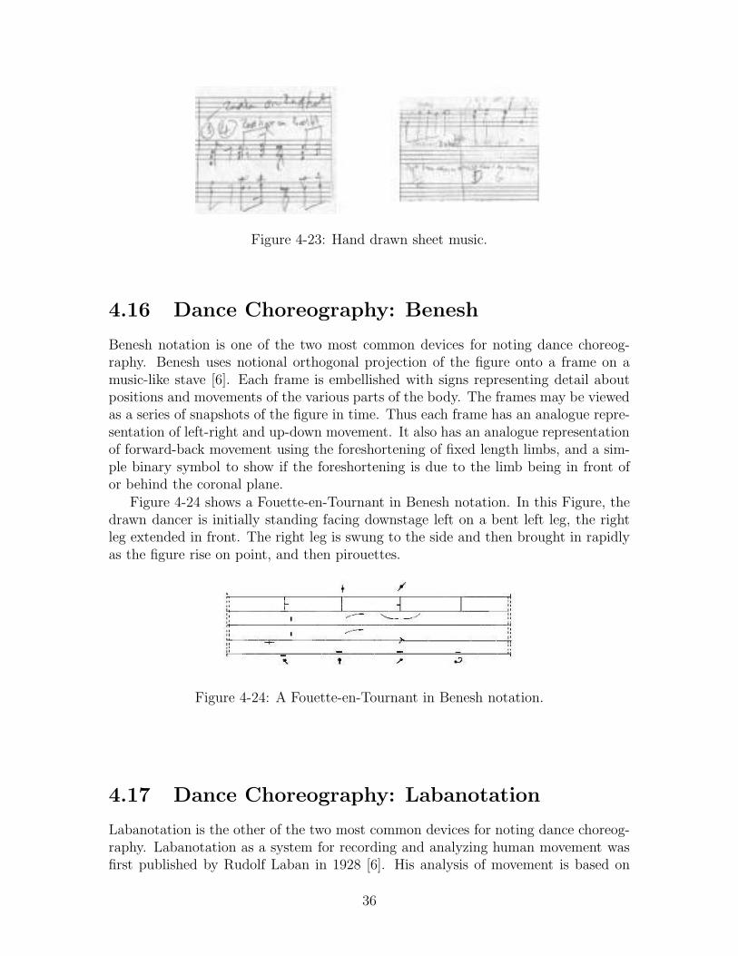
Figure 4-23: Hand drawn sheet music.
4.16 Dance Choreography: Benesh
Benesh notation is one of the two most common devices for noting dance choreog-raphy. Benesh uses notional orthogonal projection of the figure onto a frame on amusic-like stave [6]. Each frame is embellished with signs representing detail aboutpositions and movements of the various parts of the body. The frames may be viewedas a series of snapshots of the figure in time. Thus each frame has an analogue repre-sentation of left-right and up-down movement. It also has an analogue representationof forward-back movement using the foreshortening of fixed length limbs, and a sim-ple binary symbol to show if the foreshortening is due to the limb being in front ofor behind the coronal plane.
Figure 4-24 shows a Fouette-en-Tournant in Benesh notation. In this Figure, thedrawn dancer is initially standing facing downstage left on a bent left leg, the rightleg extended in front. The right leg is swung to the side and then brought in rapidlyas the figure rise on point, and then pirouettes.
Figure 4-24: A Fouette-en-Tournant in Benesh notation.
4.17 Dance Choreography: Labanotation
Labanotation is the other of the two most common devices for noting dance choreog-raphy. Labanotation as a system for recording and analyzing human movement wasfirst published by Rudolf Laban in 1928 [6]. His analysis of movement is based on
36

spatial, anatomical, and dynamic principles. In Figure 4-25, the Parts Girl illustratessome of the symbols used to represent body parts in Labanotation.
Figure 4-25: A figure illustrating the parts of a dancer in labanotation.
Labanotation has time running continuously up the page. The vertical length andpositioning of a symbol represent when and for how long the action occurs. Differentcolumns of the vertical stave represent different parts of the body. Additional signscan be added to represent additional detail.
LabanPad contains a handwriting recognition algorithm specialised in Labanota-tion. As the user writes down Labanotation symbols using a pen, they are analysed,tokenised and clearly displayed [19]. Figure 4-26 shows a sample of a hand drawndance motion in labanotation that is recognized using LabanPad.
Figure 4-26: A hand drawn dance motion in Labanotation on the left and its cleanedversion on the right as recognized by LabanPad [19].
4.18 Sports Games: Football
Figure 4-27 is a football play diagram. Players are represented by circles and theirmotion is represented by arrows. In this diagram, the play starts with the QB (quar-terback) reversing out and handing off to the RB (runningback). The quarterback QBsprints to the left and fakes a pass, hopefully freezing a defender for a moment. Thecenter and guard double-team the nose guard, with FB (fullback) Cameron Hamiltonproviding the key block by taking on the linebacker. RB reads FB’s block and goes
37

inside or toward the sideline. If the linebackers start cheating on the run, QB willkeep the ball and look for the TE (tight end) over the middle or a WR (wide receiver)going deep.
Figure 4-27: A football play diagram.
4.19 Sports Games: Basketball
Figure 4-28 is a basketball play diagram for zone offence. In this diagram, the playersare represented by open circles with numbers inside. The ball is represented by asmaller filled in circle. The motion of the players is represented by arrows. Themotion of the ball is represented by dotted arrows. In Figure 4-28 player 1 beginsthe attack with a pass to a wing (player 5). Player 5 then passes to player 4 whohas moved to the corner, player 3 moves to the ballside high post, and player 2 dropsdown to take a low post on the offside.
38

Figure 4-28: A basketball play diagram for zone offense.
4.20 Sports Games: Baseball
Figure 4-29 is a diagram of a baseball play of a pitcher covering first base. Circlesrepresent the players in the field. Triangles represent players at bat. A squigglearrow is the direction of the hit ball. An arrow is the direction of the movement ofthe players. A dotted arrow is the throwing of the ball.
Figure 4-29: Baseball play of pitcher covering first base.
The Figure 4-29 suggest the following: The first base should be a good distanceoff the plate in order to cover more territory. If a ball is hit to him and he is unableto get to first in time the pitcher should cover first base. On any hit ball to the rightside the pitcher should move in direction of first base. The pitcher should run towardsfirst base. The first baseman tosses ball underhanded to pitcher, tossing ball before
39

pitcher gets to first, leading the pitcher with the toss. The pitcher should run pastthe base, running on the inside to the base.
4.21 Interior Design
Figure 4-30 shows the interior design of a bathroom. Notice that there are severalstandard symbols, such as that of the toilet, and the tub that could be recognizedusing the technique described in this proposal. Figure 4-31 shows the interior designfor an entire floor. We again see the standard symbols present in the bathroom, butwe also see other symbols in other room such as sofas, tables, chairs, and beds.
Figure 4-30: The interior design of a bathroom.
40
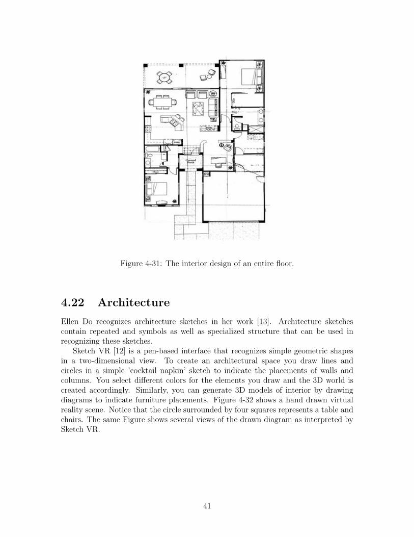
Figure 4-31: The interior design of an entire floor.
4.22 Architecture
Ellen Do recognizes architecture sketches in her work [13]. Architecture sketchescontain repeated and symbols as well as specialized structure that can be used inrecognizing these sketches.
Sketch VR [12] is a pen-based interface that recognizes simple geometric shapesin a two-dimensional view. To create an architectural space you draw lines andcircles in a simple ’cocktail napkin’ sketch to indicate the placements of walls andcolumns. You select different colors for the elements you draw and the 3D world iscreated accordingly. Similarly, you can generate 3D models of interior by drawingdiagrams to indicate furniture placements. Figure 4-32 shows a hand drawn virtualreality scene. Notice that the circle surrounded by four squares represents a table andchairs. The same Figure shows several views of the drawn diagram as interpreted bySketch VR.
41

Figure 4-32: A hand drawn virtual reality scene and several views of the virtual realityscene created by Sketch VR.
42

Chapter 5
Language
This thesis proposal proposes a domain description language to describe the domain-specific details for a sketch recognition system. The language is based on shape,although non-shape information, including display and editing behaviors, can also bespecified. The language will consist of pre-defined shapes, constraints, editing behav-iors, and display methods, as well as mechanisms for specifying a domain descriptionand extending the language. The power of the language is derived from carefullychosen predefined building blocks. An example of a description for an OpenArrow(Figure 5-1) is in Figure 5-2.
Figure 5-1: An open arrow.
The next few pages will document the current state of the language. Many ques-tions still exist, including proper syntax and components of the language. The answersto these questions will be fleshed out through the completion of the thesis.
5.1 Pre-Defined Shapes
The language will include a number of predefined primitive and non-primitive shapesused in defining other shapes. Non-primitive shapes can be described hierarchicallyusing the primitive shapes; they are included as syntactic sugar to simplify shapedescriptions. The primitive shapes are Shape, Point, Path, Line, BezierCurve,and Spiral.
To choose these primitive shapes, we examined the domains listed in Section 4.We completely described the shapes in a number of domains, including Benesh dancenotation, sheet music, and UML class diagrams. We also partially described theshapes in the domains of Course of Action diagrams and Mechanical Engineering.We found that all of the shapes that we examined could be made up of the primitives
43

(define sketch-shape OpenArrow
(description "An arrow with an open head")
(components
(Line shaft)
(Line head1)
(Line head2))
(constraints
(coincident shaft.p2 head1.p2)
(coincident shaft.p2 head2.p2)
(coincident head1.p2 head2.p2)
(equal head1.length head2.length)
(ccAcuteMeet head1 shaft)
(ccAcuteMeet shaft head2)
(aliases
(Point head shaft.p2)
(Point tail shaft.p2)
)
(display
(original-strokes)
)
)
Figure 5-2: The description for an arrow with an open head
chosen. Ellipses and arcs we found to be common shapes, but we were able to definethem using the primitive shape Spiral. We defined Spirals such that an ellipse isa specialized Spiral where the growth-factor is equal to 1. Spirals have a startinglength and a width to allow for stretched out spirals, such as the one shown inFigure 5-3.
Figure 5-3: A hand drawn spiral.
Since some common shapes may be clumsy to describe using only the primitiveshapes, several other predefined shapes are defined. These include, among others,Ellipse, Circle, and Rectangle
The OpenArrow in Figure 5-2 is composed of three primitive shapes. The lan-guage uses an inheritance hierarchy; Shape is an abstract shape which all othershapes extend. Shape provides a number of accessible components and propertiesfor all shapes, including boundingbox, centerpoint, width, height, and time. Eachpredefined shape also has additional accessible components and properties, for exam-ple, for a Line these include p1, p2 (the endpoints), midpoint, length, angle, slope,
44

and y-intercept. Accessible components and properties for a shape can be used inshape descriptions containing that shape. When defining a new shape the accessiblecomponents and properties are those defined by Shape, and those defined by thecomponents and aliases section. The accessible properties of the primitive shapesare defined within the recognition system. The accessible properties of non-primitiveshapes are pre-defined in the language’s syntax.
The pre-defined shapes are:
Shape
The abstract shape that all shapes extend. The accessible properties for allshapes are bounding-box, which is the smallest rectangle parallel to the horizonthat can be placed around the shape, center-point, which is the center of thebounding-box, width, the height of the bounding-box, height, the width ofthe bounding-box, and time, the time when the shape was completed. Timeis included to allow constraints to specify stroke order or direction.
Point
A point. The accessible properties are the x and y values of the point.
Path
A continuous stroke, not necessarily straight. The accessible properties arestart-point, end-point, length and num-loops.
Line
A straight line. The accessible properties are start-point, end-point, midpoint,
length, slope, y-intercept, and angle. The angle is between 0 and 360,and is the angle between a directional horizontal line pointing to the right andthe Line directed from start-point to end-point. All Line’s are also Paths.
BezierCurve
A curve defined by four points, its two endpoints and two control points. Theaccessible properties include start-point, end-point, control-point1, andcontrol-point2.
Spiral
A spiral starting from one angle and radius, ending at another. The radiuscontinually gets larger or smaller throughout the spiral, with the amount spec-ified by the grow-factor. There is a start angle and end angle specifiedfor the spiral. The center of the spiral is the rotation point. The accessi-ble properties are start-point, end-point, center-point, start-angle,
end-angle, large-radius, small-radius, num-loops, degrees, and grow-factor.degrees = end-angle − start-angle, which may be larger than 360 if the spi-ral includes several loops, and the number of loops, num-loops, equals degrees/ 360.
ClosedPath
A path in which the last point is at the same point as the first, making a loop.This shape is an extension of Path and has the same accessible properties.
45

Polygon
A closed path comprised of line segments, and containing the same accessibleproperties as a Closed Path.
EllipseArc
An arc, a portion of an ellipse. This is also a Spiral where the grow-factor
is equal to 1. This contains the same accessible properties as a Spiral. If theend-angle - start-angle >= 360, the entire ellipse is drawn.
Ellipse
An ellipse in any orientation. This is an ellipse defined by the four points ofa rectangle surrounding it. An Ellipse is a specific form of an EllipseArc
where end-angle - start-angle equals 360. It includes the same accessibleproperties as the EllipseArc.
Circle
A circle. This is the same as an ellipse where radius1 = radius2. The acces-sible properties include center-point and radius.
Triangle
A triangle. The accessible properties include the three points of the trianglepoint1, point2, and point3.
Rectangle
A rectangle in any orientation. The accessible properties include the four linesof the rectangle: line1, line2, line3, line4 and center-point, width,
height, and rotation. The rotation defines the angle between the horizontalplane and the line denoting the width of the rectangle.
RoundedRectangle
A rectangle with rounded corners. The accessible properties are the same as aRectangle.
Square
A rectangle where the height and width are equal. The accessible propertiesare the same as a Rectangle.
5.2 Pre-defined Constraints
New shapes are defined in terms of previously defined shapes and constraints be-tween them. For instance, the OpenArrow in Figure 5-2 contains the constraint(ccAcuteMeet head1 shaft ), which ensures that head1 and shaft meet at a pointand form an acute angle in a counter-clockwise direction from head1 to shaft.
A number of predefined constraints are included in the language, such as perpendicular.If a sketch grammar consists of only the constraints above, the shape is rotationallyinvariant. There are also predefined constraints that are valid only in a particular ori-entation, such as posSlope. There is an additional constraint: isRotatable, which
46

implies the shape can be found in any orientation. If isRotatable is specified alongwith an orientation-dependent constraint, there must be an angle, horizontal, orvertical constraint specified, which serves to define the orientation and set a relativecoordinate system.
A number of predefined constraints are included in the language to facilitate shapedefinitions.
horizontal lineline is a horizontal line. The slope of the line is 0.Orientation Dependent
vertical line
line is a vertical line. The slope of the line is undefined.Orientation Dependent
posSlope line
line has a positive slope. Both the x-value and the y-value of one endpoint of theline are less than the x-value and the y-value of the other endpoint.Orientation Dependent
negSlope line
line has a negative slope. The x-value of p1 is less than the x-value of p2 and they-value of p1 is greater than the y-value of p2, where Point p1 and Point p2 are thetwo endpoints.Orientation Dependent
leftOf point1 point2
point1 is to the left of point2 on the screen. The x-value of point1 is less thanthe x-value of point2 . This is the same as (rightOf point2 point1 ), unless theyshare the same x-value.Orientation Dependent
rightOf point1 point2
point1 is to the right of point2 on the screen. The x-value of point1 is greaterthan the x-value of the point2 . This is the same as (leftOf point2 point1 ), unlessthey share the same x-value.Orientation Dependent
above point1 point2
point1 is above point2 on the screen. The y-value of point1 is less than the y-valueof point2 . This is the same as (below point2 point1 ), unless they share the samey-value.Orientation Dependent
below point1 point2
point1 is below point2 on the screen. The y-value of point1 is greater than they-value of point2 . This is the same as (above point2 point1 ), unless they sharethe same y-value.Orientation Dependent
47

sameHPos point1 point2
point1 and point2 have the same horizontal position, i.e., they share the same x-value. This implies that (above point1 point2 ) and (below point1 point2 ) areboth false.Orientation Dependent
sameVPos point1 point2
point1 and point2 have the same vertical position, i.e., they share the same y-value. This implies that (leftOf point1 point2 ) and (rightOf point1 point2 )are both false.Orientation Dependent
aboveLeft point1 point2
(above point1 point2 ) AND (leftOf point1 point2 )Orientation Dependent
aboveRight point1 point2
(above point1 point2 ) AND (rightOf point1 point2 )Orientation Dependent
belowLeft point1 point2
(below point1 point2 ) AND (leftOf point1 point2 )Orientation Dependent
belowRight point1 point2
(below point1 point2 ) AND (rightOf point1 point2 )Orientation Dependent
centeredBelow point1 point2
(below point1 point2 ) AND (sameVPos point1 point2 )Orientation Dependent
centeredAbove point1 point2
(above point1 point2 ) AND (sameVPos point1 point2 )Orientation Dependent
centeredLeft point1 point2
(leftOf point1 point2 ) AND (sameHPos point1 point2 )Orientation Dependent
centeredRight point1 point2
(rightOf point1 point2 ) AND (sameHPos point1 point2 )Orientation Dependent
isRotatable [shape]The shape can be found in any orientation. If any Orientation Dependent constraintsare listed for this shape, it must have a line defined with a particular angle (using oneof the following constraints: angle, horizontal, or vertical). For example, thetwo ccAngleMeet constraints in the OpenArrow from Figure 5-2 could have beenreplaced with:
48

(isRotatable)
(horizontal shaft)
(posSlope head1)
(negSlope head2)
(leftOf shaft.p1 shaft.p2)
(leftOf head1.p1 shaft.p2)
(leftOf head2.p1 shaft.p2),
in which case the shape is first rotated to make the shaft horizontal, and then therest of the constraints are checked.
ccAngleD line1 line2 degrees
Both lines have their two endpoints labelled point1 and point2. line1 is a directionalline extending from point1 to point2. line2 is a directional line extending from point1to point2. The angle between line1 and line2 is measured in a counterclockwisedirection when line2 is translated such that point1 of line2 and point1 of line1are in the same location. degrees specifies the number of degrees between the twolines when traversing from line1 to line2 in a counter clockwise direction. For eachset of two lines, there is only one possible value between 0 and 360 that could be true.
ccAngle line1 line2 degrees
line1 and line2 are not directional. The angle between line1 and line2 is mea-sured in a counter clockwise direction when the lines are extended to infinity. degreesspecifies the number of degrees between the two lines when traversing from line1 toline2 in a counterclockwise direction. For each set of two lines, there is only onepossible value between 0 and 180 that could be true.
ccAcute line1 line2
The angle between line1 and line2 when traversing counterclockwise, is an acuteangle, measured as in ccAngle, when the lines are extended to infinity.
ccObtuse line1 line2
The angle between line1 and line2 when traversing counterclockwise, is an obtuseangle, measured as in ccAngle, when the lines are extended to infinity.
ccAcuteMeet line1 line2
The lines line1 and line2 meet at their endpoints and form an acute angle in thecounterclockwise direction from line1 to line2 .
ccObtuseMeet line1 line2
The lines line1 and line2 meet at their endpoints and form an obtuse angle in thecounterclockwise direction from line1 to line2 .
angle line degrees
This constraint specifies that the angle property of the line is degrees . A horizontalline pointing to (from the start-point to the end-point) the right is defined to havean angle of 0. A vertical line pointing up is defined to have an angle of 90. A horizontalline pointing to the right is defined to have an angle of 180. A vertical line pointingdown is defined to have an angle of 270.Orientation Dependent
49

perpendicular line1 line2
This specifies that two lines are perpendicular.
parallel line1 line2
This specifies that two lines are parallel.
collinear point1 point2 point3
This specifies that three points are on the same line.
sameSide line point1 point2
point1 and point2 are on the same side of line . If you draw a line between point1
and point2 , this new line does not cross line when line is extended to infinity.
oppositeSide line point1 point2
point1 and point2 are on the different sides of line . If you draw a line betweenpoint1 and point2 , this new line crosses line when line is extended to infinity.
coincident point1 point2
This constraint confirms that two points are in the same location.
connected lac1 lac2
lac1 and lac2 are either lines, arcs, or curves. One endpoint from lac1 and oneendpoint from lac2 are coincident.
meet lac shape
lac is either a line, arc, or curve. One endpoint of lac intersects the strokes or linessegments of shape .
intersect shape1 shape2
The strokes or line segments of the two shapes intersect.
tangent shape1 shape2
The borders of the two shapes touch, but do not intersect. The two shapes touch(there is a point from shape1 and a point from shape2 that are coincident) butthey do not intersect. There must also be several points from shape1 that are notcoincident with any point from shape2 , and vice-versa.
contains shape1 shape2
The bounding box of shape2 is inside of shape1.
concentric shape1 shape2
The center of shape1 and the center of shape2 are coincident.
centered-in shape1 shape2
(contains shape2 shape1 ) AND (concentric shape2 shape1 ).
smaller shape1 shape2
The area of the bounding box of shape1 is smaller than the area of the boundingbox of shape2 .
50

larger shape1 shape2
The area of the bounding box of shape1 is larger than the area of the bounding boxof shape2 .
near shape1 shape2
shape1 is near shape2 . Near is usually on the order of 10-20 pixels although theexact parameter is set by the recognition system.
draw-order shape1 shape2
shape1 was drawn before shape2 .
= value1 value2
This constraint compares two values to check if they are equal.
> value1 value2
This constraint checks if value1 is greater than value2.
or constraint1 constraint2
This constraint checks that at least one of the two constraints listed is true.
not constraint1
This constraint confirms that the constraint listed is not true.
5.3 Pre-defined Editing Behaviors
We need the ability to describe editing gestures so that the recognition system candiscriminate between sketching (pen gestures intended to leave a trail of ink) andediting gestures (pen gestures intended to change existing ink), and because editingbehaviors are different in different domains.
In order to encourage interface consistency, the language will include a number ofpredefined editing behaviors built using the actions and triggers above. The developercan then choose to use these editing behaviors if she wishes. One such example isScribbleDelete, which defines that if you scribble-over the strokes of a shape, theshape is deleted.
When defining a new editing behavior particular to a domain, there are two thingsto specify: the trigger – what signals an editing command – and the action – whatshould happen when the trigger occurs. For example, an editing description is definedin Figure 5.3. In this description, a rectangle is moved along with the motion of penif the sketcher presses and holds the pen over the bounding box of the rectangle fora brief time and then moves the pen.
The language has a number of predefined triggers and actions to aid in describingediting behaviors. To give an example(rubber-band shape-or-selection fixed-point move-point [new-point])
translates, scales, and rotates the shape-or-selection so that the fixed-point remainsin the same spot, but that the move-point translates to the new-point. If new-pointis not specified, move-point translates according to the movement of the mouse.rubber-band is used in the editing definition in Figure 5.3. In this definition, if
51

(define sketch-edit MoveRectangle
(components
(Rectangle r)
)
(trigger
(click-hold-drag r.bounding_box)
)
(action
(move r)
)
)
(define sketch-edit MoveArrowTail
(components
(OpenArrow oa)
)
(trigger
(move oa.tail)
)
(action
(rubberband oa oa.head oa.tail)
)
)
the user moves the tail of an arrow, then the entire arrow will scale and rotate to toensure that the head remains fixed and the tail moves as necessary.
5.3.1 Triggers
The possible triggers include all those listed below as well as all of the actions listedin the next subsection, allowing for “chain-reaction” editing.
click shape/selection
Click the mouse on a shape or selection .
double-click shape/selection
Double click the mouse on a shape or selection .
click-hold shape/selection
Click and hold down the mouse over a shape or selection for a time greaterthan 0.4 seconds.
click-hold-drag shape/selection
Click and hold down the mouse over a shape or selection greater than 0.4seconds, then move the mouse with the mouse button held down.
draw shape/shape-composition
Draw a particular shape or shape-composition .
52

pen-over shape/selection
Hold the pen over of an shape or selection . For instance, you may scalinghandles to appear if the pen rests over one of the corners of a rectangle.
draw-over new shape old shape/selection
Draw a new-shape on top of an old-shape or selection . For instance, youmay wish to draw an X over an object to signify deletion.
scribble-over shape/selection
Draw a scribble over a shape or selection . A scribble is defined as a backand forth motion repeatedly crossing over an object.
encircle shapes
Draw a closed path around a group of shapes . This trigger may be used toselect a collection of shapes.
Any editing action(listed in the Actions subsection)
5.3.2 Actions
Once the trigger occurs, any number of particular editing actions will occur. Thepossible editing actions are listed below.
wait milliseconds
Wait for a certain number of milliseconds before doing the next action.
select shapes
Select the collection of shapes specified.
deselect selection
Deselect the collection of shapes specified.
color shape/selection color
Color the shape or selection a particular color .
delete shape/selection
Delete the specified shape or selection .
move shape/selection [x-shift y-shift]
If the x-shift and y-shift are not specified, then translate the specifiedshape or selection according to the motion of the mouse. If x-shift andthe y-shift are specified, translate according to the amount specified.
rotate shape/selection fixed-point [amount]
Rotate the specified shape or selection the amount specified. Rotation oc-curs around the fixed-point. If the amount is not specified, then rotate accordingto the motion of the mouse.
53

scale shape/selection fixed-point [amount]
Scale the specified shape or selection the amount specified. The fixed-pointremains fixed, and the other points move to adjust to the scaling. For instance,when dragging the bottom corner of a square the fixed-point could be theupper corner of the square. If the amount is not specified, then scale accordingto the motion of the mouse.
resize shape/selection width height
Resize the bounding box of the shape or selection specified to the width
and height specified. This is done by a combination of scale and translatecommands.
rubber-band shape/selection fixed-point move-point
Translate, scale and rotate the shape or selection specified so that thefixed-point remains in the same spot, but that the move-point translatesaccording to the movement of the mouse, and the entire shape or selectionremains solid.
rubber-band shape/selection fixed-point old-point new-point
Translate, scale and rotate the shape or selection specified so that the fixed-pointremains in the same spot, but that the old-point translates according to thelocation of the new-point and the entire shape or selection remains solid.
show-handle type point
Shows a specialized cursor handle at a particular point . The type can beNORMAL, MOVE, SCALE, ROTATE, DRAG, PAINT, or TEXT.
5.4 Pre-defined Display Methods
Since the strokes remain viewable after they are drawn, the language can define whatshould be displayed after a shape is recognized. For example, we can specify that theoriginal strokes should remain, or that the cleaned-version of the strokes should bedisplayed. In the cleaned-version of the strokes, messy lines are replaced by straightlines and messy curves are replaced by clean curves. Another option is to display theideal-version of the strokes. In this case, lines that are supposed to connect at theirend points actually connect and lines that are supposed to be parallel are actuallyshown as parallel. In the ideal-version of the strokes, all of the noise from sketchingis removed.
It may be that we don’t want to show any version of the strokes at all, but someother picture. In this case, there are two ways to proceed. We can create a picturecomposed of circles, lines, rectangles and other shapes, specifying where each of thecomponents should be drawn on the screen. We can also place a .gif or .bmp picturefile at a specified location, size, and rotation.
Below are listed the pre-defined display methods available when defining how todisplay a shape or its components after the shape is recognized. The arguments insquare brackets are optional.
54

original-strokes shape [color]
The original strokes of shape will be drawn in the color specified. If no color
is specified, they will be drawn in black.
cleaned-strokes shape [color]
Each of the original strokes of shape will be fit to a point, line, circle, arc,polyline, and a complex shape. When displaying the cleaned strokes, each strokeshape will be replaced by the best fit interpretation of those listed above. Thecleaned strokes will drawn in the color specified. If no color is specified, theywill be drawn in black.
ideal-strokes shape [color]
When shape is defined in the language, certain constraints are defined. Forinstance, two lines may be constrained to meet at their endpoints. When dis-playing the ideal strokes, shape will be drawn such that these lines actuallydo meet at their endpoints. This method draws shape without any noise. Theideal strokes will be drawn in the color specified. If no color is specified, theshape will be drawn in black.
circle center-point radius [color]
This draws a circle specified by the radius and center-point . The circle willbe drawn in the color specified. If no color is specified, the circle will bedrawn in black.
line start-point end-point [color]
This draws a line from the start-point to the end-point in the specifiedcolor . If no color is specified, the line will be drawn in black.
point x y [color]
This draws a point at the specified location in the specified color . If no color
is specified, the point will be drawn in black.
rectangle upper-left-corner-point lower-right-corner-point [color]
This draws a rectangle parallel to the window from the upper-left-corner-pointto the lower-right-corner-point in the specified color . If the color isnot specified, the rectangle will be drawn in black.
text string start-point size [color]
This draws a text string at the specified location. size specifies the size of thefont. If the color of the text is not specified, the text will be drawn in black.
image filename start-point [size] [rotation]
This draws the image in the specified filename at the specified location, size ,and rotation . If size is not specified, the picture is drawn its original size.If no rotation is specified, the rotation is set to 0.
55

Chapter 6
Specifying a Domain Description
The purpose of the language is to allow developers to describe the domain specificinformation about the sketch recognition interface they would like to build. The do-main specific information is specified in a domain description. A domain descriptionis built using the predefined shapes, constraints, editing behaviors, and display meth-ods from Section 5 and using the syntax as specified by the language. The chapterdescribes the syntax of a domain description.
A domain description contains a list of the domain shapes, shape interactions, andediting behaviors in the language, as well as definitions for each of the shapes, shapeinteractions, and editing behaviors described in the list. These shape descriptions canbe hierarchical and can refer to other shapes in the language.
In Section 4.1, UML (Unified Modelling Language) [5] class diagrams are de-scribed. We can recognize UML class diagrams by writing a domain description,which describes the shapes in the domain. The domain description for UML classdiagrams is specified in the appendix. We will use this domain to help illustratethe concepts explained in this chapter, and refer to several examples in the UMLclass diagram domain description throughout this chapter. Section 4.1 also includesa sketched and interpreted picture of a UML class diagram for aid in understandingthese examples.
To create a domain description, one must specify the list of shapes and shapeinteractions in the domain. One must also specify how each of the shapes and theirinteractions are drawn, displayed, and edited.
A goal of the language is to allow inclusion into the domain description pertinentinformation which describes the drawing process and may aid in recognition. A shapedefinition includes primarily geometric information, but can include other drawinginformation that may be helpful to the recognition process, such as stroke order orstroke direction. With the addition of these constraints, the Graffiti language, suchas described in Section 4.14, can also be described using this language.
The language can also specify other information helpful to the recognition process,such as constraints that usually occur, even if the recognition system should stillrecognize this shape even if the shape does not satisfy this constraint. For instance,it may be helpful to know that a particular shape is often drawn with a particularstroke order. In this sense, we may wish to specify the popular stroke order. However,
56

since the shape may sometimes be drawn using a different stroke order, we may wishto specify that this is a soft constraint, not a hard constraint.
6.1 Listing the Domain Shapes and Shape Inter-
actions
Domain descriptions include specifications of how domain shapes and shape interac-tions are drawn, displayed, and edited. In this section we list the domain shapes anddomain shape interactions.
The domain shapes and their interactions are listed within the domain description,so that the compiler can confirm that each shape is properly defined and can removedefinitions of unused shapes to provide faster and more accurate recognition.
6.1.1 Domain Shapes
A domain shape is a shape that is meaningful in the domain. Geometric shapesusually occur in several domains and are the building blocks of the domain shapes.
For instance, in the domain of UML class diagrams, the domain shapes (followedby their geometric components) are:
• UML Class (represented by a rectangle)
• UML Interface (represented by a circle)
• UML Interface Association (represented by a line)
• UML Dependency Association (represented by a open-headed arrow)
57

• UML Aggregation Association (represented by a diamond-headed arrow)
• UML Inheritance Association (represented by a triangle-headed arrow)
Each of these shapes should be recognized by the recognition system. Furthersections indicate how the language facilitates describing how these shapes are drawn,as well as what should be displayed and how the shapes can be edited after they arerecognized.
6.1.2 List of Domain Shapes
For each domain, the sketch recognition system needs a list of the domain shapesto be recognized; we call this list the list of domain shapes. This list is part of thedomain description.
The format for the list is:
(list sketch-domain-shapes domain-name(shape-or-composition-name)pattern-expression(shape-or-composition-name)pattern-expression...
)
The domain-name is a variable specifying the name of the domain. The shape-or-composition-name specifies the name of a shape or shape composition to be recognizedin the domain. The pattern-expression specifies how many times a domain object isexpected to occur in a particular sketch in the domain. For example, in mechanicalengineering, every diagram is expected to contain at most one symbol for gravity, andin electrical engineering, every electrical circuit has at least one ground,
The pattern-expression can be either
1. * : specifying that a domain object can occur any number (0 or more) times inthe domain
58

2. positive integer n : specifying that a domain object will occur n times in thedomain
3. a positive integer n followed by a plus sign (+) : specifying that a domain objectwill occur n or more times in the domain
4. a positive integer n followed by a minus sign (-) : specifying that a domainobject will occur n or fewer times in the domain
5. nothing : same as *
6. + : same as 1+
7. - : same as 1-
The example below shows the list of domain shapes for UML Class Diagramsand indicates that there can be any number of each of the shapes in the UML ClassDiagram domain.
(list sketch-domain-shapes UML
(DependencyAssociation)*
(AggregationAssociation)*
(InheritanceAssociation)*
(InterfaceAssociation)*
(InterfaceClass)*
(GeneralClass)*
(Text)*
)
6.1.3 Domain Shape Interactions
A domain shape interaction describes a collection of shapes that are commonly foundtogether in the domain. Defining domain shape interactions provides two significantbenefits. Domain shape interactions can be used by the recognition system to pro-vide top-down recognition and editing behaviors can by applied specifically to shapeinteractions, allowing the movement of one shape to cause the movement of another.
In the domain of UML class diagrams, the domain shape interactions are:
• A UML General Class combined with a UML Association with the tail of thearrow inside or near the UML General Class.
• A UML General Class combined with a UML Association with the head of thearrow inside or near the UML General Class.
59

• A UML Interface Class combined with a UML Association with the tail of thearrow inside or near the UML Interface Class.
• A UML Interface Class combined with a UML Association with the head of thearrow inside or near the UML Interface Class.
• 2 UML General Classes combined with a UML Association with the head of thearrow inside or near one UML General Class and the tail of the arrow inside ornear the other UML General Class.
• A UML General Class and a UML Interface Class combined with a UML Inter-face Association with the tail of the arrow inside or near one UML Class andthe head of the arrow inside or near the other UML Class.
The shape interaction will be defined within the domain description, specifiedlater. We can define editing behaviors for the shape interaction, allowing the editingof one shape to affect another. For instance, visually, UML Associations are attachedto UML Classes. When we move a UML Class, we would like the head or tail of theUML Association attached to the UML Class to move with the class in a rubber bandfashion.
Further sections describe how the language facilitates the description of how theseshape interactions are drawn, as well as what should be displayed and how the shapescan be edited after the shapes are recognized.
60

6.1.4 List of Domain Shape Interactions
For each domain, the sketch recognition system needs a list of the domain shapeinteractions to be recognized.
The example below shows the list of domain shape interactions for UML classdiagrams.
(list sketch-domain-shape-interactions UML
(GeneralClassAssociationTail)*
(GeneralClassAssociationHead)*
(InterfaceClassAssociationTail)*
(InterfaceClassAssociationHead)*
(GGClassAssociation)*
(GIClassAssociation)*
)
6.2 Defining Shapes
A shape definition describes the geometrical properties of a shape. A shape definitionis composed of six sections:
1. The description contains a textual description of the shape, e.g., “an arrow witha triangle-shaped head.”
2. The is-a section specifies any class of abstract shapes (Section 6.2.1) that theshape may be a part of. This is similar to the extends property in Java. Allshapes extend the abstract shape Shape.
3. The components section lists the components of the shape, and describes whichshapes combine to form the shape. For example, the TriangleArrow in Fig-ure 6-1 is composed of the OpenArrow from Figure 5-2 and a Line. Compo-nents can be accessed hierarchically.
4. The constraints section specifies relationships between the components. Forexample, in the TriangleArrow in Figure 6-1, (coincident head3.p1 head1.p2)specifies that an endpoint of head3 and an endpoint of head1 are located at thesame point.
The constraints section can specify both hard constraints, such as the one listedabove, and soft constraints, which are specified by the keyword soft. Hardconstraints are always satisfied in the shape, but soft constraints may not be.Soft constraints can aid recognition by specifying relationships that usuallyoccur. For instance, in Figure 6-1 the shaft of the arrow is commonly drawnbefore the head of the arrow, but the arrow should still be recognized even ifthis constraint is not satisfied.
5. The aliases section allows us to compute certain properties and name them foruse later. For instance, in Figure 6-1, head1 is defined and used in a constraint
61
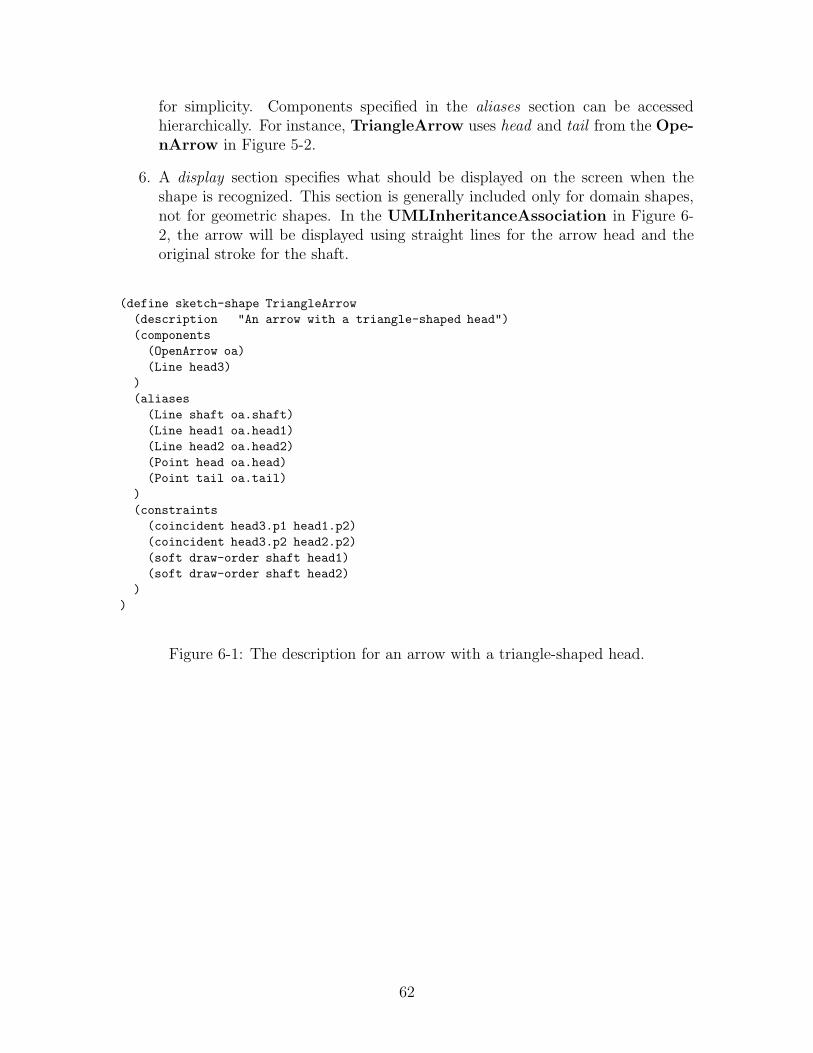
for simplicity. Components specified in the aliases section can be accessedhierarchically. For instance, TriangleArrow uses head and tail from the Ope-nArrow in Figure 5-2.
6. A display section specifies what should be displayed on the screen when theshape is recognized. This section is generally included only for domain shapes,not for geometric shapes. In the UMLInheritanceAssociation in Figure 6-2, the arrow will be displayed using straight lines for the arrow head and theoriginal stroke for the shaft.
(define sketch-shape TriangleArrow
(description "An arrow with a triangle-shaped head")
(components
(OpenArrow oa)
(Line head3)
)
(aliases
(Line shaft oa.shaft)
(Line head1 oa.head1)
(Line head2 oa.head2)
(Point head oa.head)
(Point tail oa.tail)
)
(constraints
(coincident head3.p1 head1.p2)
(coincident head3.p2 head2.p2)
(soft draw-order shaft head1)
(soft draw-order shaft head2)
)
)
Figure 6-1: The description for an arrow with a triangle-shaped head.
62

(define sketch-shape UMLInheritanceAssociation
(is-a UMLGeneralAssociation)
(components
(TriangleArrow arrow)
)
(aliases
(Point head arrow.head)
(Point tail arrow.tail)
(Line shaft arrow.shaft)
)
(display
(original_strokes arrow.shaft)
(cleaned_strokes arrow.head1 arrow.head2 arrow.head3)
)
)
Figure 6-2: The domain shape UML Inheritance Association is defined by the geo-metrical shape TriangleArrow from Figure 6-1.
6.2.1 Defining Abstract Shapes
In the UMLInheritanceAssociation defined in Figure 6-2, the is-a section spec-ifies that the UMLInheritanceAssociation is an extension of the abstract shapeUMLGeneralAssociation. Abstract shapes cannot be drawn and have no shapeassociated with them; they represent a class of shapes that have similar attributes orediting behaviors. These attributes can be defined once on the abstract shape ratherthan for each domain shape.
An abstract shape is defined similarly to a regular shape, except it has a requiredsection instead of a components section. Each shape which extends the abstract shapemust define each variable listed in the required section, in its components or aliasessection.
Figure 6-3 presents a diagram of the inheritance hierarchy for the abstract andnon-abstract shapes in the UML class diagrams domain. In UML, UMLDependen-cyRelationship, the UMLInheritanceRelationship, the UMLAggregationRe-lationship, and the UMLInformationRelationship all have the same editing be-havior, thus they are all UMLGeneralAssociations. The abstract shape UML-GeneralAssociation from Figure 6-4 itself extends UMLAssociation from Fig-ure 6-4; the required variables are used when defining editing behaviors.
63

Figure 6-3: The inheritance diagram of UML Class Diagram shapes.
(define sketch-abstract-shape UMLAssociation
(is-a Shape)
(required
(Point head)
(Point tail)
(Line shaft)
)
)
(define sketch-abstract-shape UMLGeneralAssociation
(is-a UMLAssociation )
)
Figure 6-4: The description for two abstract classes.
64

6.3 Defining Shape Interactions
A domain shape interaction describes a collection of shapes that are commonly foundtogether in the domain. For instance, in UML a UMLAssociation connects twoUMLClasses. Defining domain shape interactions provides two significant benefits.Domain shape interactions can be used by the recognition system to provide top-down recognition, and “chain-reaction” editing behaviors can be applied to shapeinteractions, allowing the movement of one shape to cause the movement of another.For instance if a UMLClass is moved, we want the UMLAssociation to remain attachedand stretch and rotate itself like a rubber band.
In the appendix, there are a large number of shape interactions defined be-cause of the complicated rules involved in linking associations and classes. For in-stance, a UMLAssociation can have zero or one UMLClass linked to its tail and canhave zero or one UMLClass linked to its head. There are additional rules statingthat a UMLGeneralAssociation can be linked only to a UMLGeneralClass, and aUMLInterfaceAssociation must be linked to only one UMLGeneralClass and onlyone UMLInterfaceClass.
If not specified otherwise, a drawn shape can be part of only one instance of ashape composition. If a single drawn shape can be part of many instances of a shapeinteractions, then we place the key word multiple before the component shape of theshape composition. In UML Class Diagrams, a single drawn UMLAssociation canonly be part of one instance of a shape composition, while a single UMLClass can bepart of many instances of UMLGeneralClassAssociationTail.
The examples in Figure 6-6 and in Figure 6-5 describe one or two general classeslinked to a general association. Both inherit from the composed shapeUMLAssociationAttachedTail, described in the next section.
(define sketch-shape-interaction UMLGeneralClassAssociationTail
(description
"A general class attached to the tail of a general association"
)
(is-a
UMLAssociationAttachedTail
)
(components
(multiple (GeneralClass ct))
(GeneralAssociation r)
)
)
Figure 6-5: Description of the composed shape of an association attached to the tailof a general class.
In Figure 6-7, we have an additional example describing a composed shape con-sisting of a Force and an Object. In the mechanical domain, forces push objects.Forces are represented by arrows and objects are represented by polygons. If a forceis said to be pushing an object, then an arrow is touching the polygon. The composed
65

(define sketch-shape-interaction UMLGenClassGenAssociation
(description
"A general association with the head and tail both attached to
a general class."
)
(is-a
UMLAssociationAttachedHead
UMLAssociationAttachedTail
)
(components
(multiple (GeneralClass ch))
(multiple (GeneralClass ct))
(Association r)
)
)
Figure 6-6: Description of the composed shape of a general association with a generalclass attached to its head and its tail.
shape ForcePushObject states that the head of the arrow touches the object. It alsospecifies that the object is usually drawn before the force.
(define sketch-shape Force
(description "An arrow is a force only if the arrow head is
pushing an object.")
(component
(OpenArrow oa)))
(define sketch-shape Object
(description "Any polygon")
(component
(Polygon p)))
(define sketch-shape-interaction ForcePushObject
(components
(Force f)
(Object o))
(constraints
(meet f.head o)
(soft draw_order o f)
))
Figure 6-7: The composed shape describing how forces push objects.
6.4 Defining Abstract Shape Interactions
We can also define abstract shape interactions. Below we have the definition of aUMLAssociationAttachedTail. This definition prevents us from having to redefine
66

the constraints and editing behaviors for many different shapes.
(define sketch-abstract-composed-shape UMLAssociationAttachedTail
(required
(Association r)
(Class ct)
)
(constraints
(contains ct r.tail)
(!contains ct r.head)
)
)
6.5 Defining Constraints
We will examine several domains (see Section 7) to find the most common constraintsneeded for defining a domain description. When an extra constraint is necessary, it canbe defined using the language’s syntax. New constraints can be defined by composingold constraints or by defining a function using a variant of Java. The exact syntax todescribe more complicated constraints has not been decided yet.
(define sketch-constraint parallel
(description
"Tests if two lines are parallel"
)
(components
(Line l1)
(Line l2)
)
(constraints
(oneof
(equal l1.slope l2.slope)
(equal l1.slope (-1 * l2.slope))
)
)
)
6.6 Defining Editing Behaviors
Editing behaviors can be defined for both shapes and shape interactions. Popularediting behaviors include movement and deletion. Each editing behavior must specifya trigger and an action. The possible triggers and actions are specified in the pre-defined list of editing behaviors.
UMLMoveClass is an editing behavior for an abstract shape. It indicates that ifyou click and hold the mouse over a UMLClass for a brief amount of time, when youbegin to move the mouse, the UMLClass will translate to follow the mouse.
UMLMoveAttachedAssociationTail is an editing behavior for an abstract com-posed shape. It indicates that whenever you move a UMLClass attached to the tail
67

of a UMLAssociation, the tail of the UMLAssociation should remain attached tothe UMLClass, but the head of the UMLAssociation should remain fixed, with theUMLAssociation rubber-banding (translating, scaling, and rotating) itself to satisfyboth constraints.
(define sketch-edit UMLMoveClass
(components
(UMLClass c)
)
(trigger
(click-hold-drag c.bounding_box)
)
(action
(move c)
)
)
(define sketch-edit UMLMoveAttachedAssociationTail
(components
(UMLAssociationAttachedTail aat)
)
(trigger
(move aat.ct)
)
(action
(rubberband r aat.r.head aat.r.tail)
)
)
68
Chapter 7
Testing and Analysis of theLanguage
Our goal is to develop a sketching language with which sketch interface developerscan describe a domain description. The sketch language will contain pre-definedshapes, constraints, display methods, and editing behaviors, to be used in the shapedescriptions. The sketch language will also provide a syntax for describing shapedescriptions. The difficulty in creating such a language is choosing a set of predefinedentities that is broad enough to support a wide range of domains, while remainingnarrow enough to be comprehensible.
7.1 Describing Domains
We plan to use the language to describe several domains, including some of thedomains listed in Chapter 4. This will ensure appropriate breadth.
7.2 Recognition System
To test that the domain descriptions we have written are correct, we will build thedomain-independent recognition system which uses a domain description to recognizesketches. The recognition system will also be used in the user studies, as describedbelow.
7.3 User Studies
We want the language to be simple enough to be comprehensible and easy to use.The language should aid in the following two goals for writing domain descriptions:
1. The descriptions produced are correct.
2. The descriptions can be produced in a short amount of time.
69

We will ask users to describe several shapes in a domain using variations of thelanguage to determine which variations of the language increase comprehensibilityand ease of use.
We would like to aid users to complete correct domain descriptions in a shortertime. The subjects will be provided with a tool to aid in the creation of a domaindescription. The tool will allow users to draw shapes to test if they are recognizable inthe domain using the recognition system described above. The tool will also generaterandom shapes that agree with a description.
We expect the users of our language to be experts in a particular domain. Weexpect these users to be computer power users. These users may or may not alsobe programmers. Thus we wish to test our language on both programmers and onnon-programmers.
70

Appendix A
Example: Domain Description forUML
A.1 arrows-library.dd
// sketch-arrow.dd
// Arrow Library
(define sketch-shape OpenArrow
(description
"A geometrical shape of a regular arrow with an open head."
)
(components
(Line shaft)
(Line head1)
(Line head2)
)
(constraints
(coincident shaft.p2 head1.p2)
(coincident shaft.p2 head2.p2)
(coincident head1.p2 head2.p2)
(ccAngleMeet head1 shaft 45)
(ccAngleMeet shaft head2 45)
(ccAngleMeet head1 head2 90)
)
(aliases
(Point head shaft.p2)
(Point tail shaft.p2)
)
)
(define sketch-shape DiamondArrow
(description
"A geometrical shape of an arrow with a diamond shaped head"
)
(components
(OpenArrow oa)
(Line d1)
71
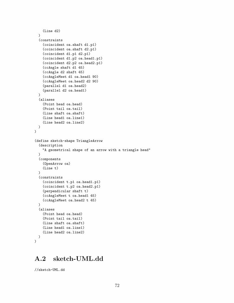
(Line d2)
)
(constraints
(coincident oa.shaft d1.p1)
(coincident oa.shaft d2.p1)
(coincident d1.p1 d2.p1)
(coincident d1.p2 oa.head1.p1)
(coincident d2.p2 oa.head2.p1)
(ccAngle shaft d1 45)
(ccAngle d2 shaft 45)
(ccAngleMeet d1 oa.head1 90)
(ccAngleMeet oa.head2 d2 90)
(parallel d1 oa.head2)
(parallel d2 oa.head1)
)
(aliases
(Point head oa.head)
(Point tail oa.tail)
(Line shaft oa.shaft)
(Line head1 oa.line1)
(Line head2 oa.line2)
)
)
(define sketch-shape TriangleArrow
(description
"A geometrical shape of an arrow with a triangle head"
)
(components
(OpenArrow oa)
(Line t)
)
(constraints
(coincident t.p1 oa.head1.p1)
(coincident t.p2 oa.head2.p1)
(perpendicular shaft t)
(ccAngleMeet t oa.head1 45)
(ccAngleMeet oa.head2 t 45)
)
(aliases
(Point head oa.head)
(Point tail oa.tail)
(Line shaft oa.shaft)
(Line head1 oa.line1)
(Line head2 oa.line2)
)
)
A.2 sketch-UML.dd
//sketch-UML.dd
72
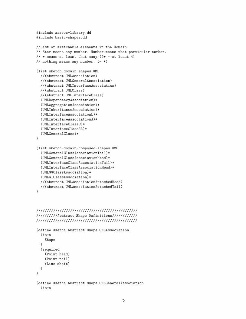
#include arrows-library.dd
#include basic-shapes.dd
//List of sketchable elements in the domain.
// Star means any number. Number means that particular number.
// + means at least that many (4+ = at least 4)
// nothing means any number. (= *)
(list sketch-domain-shapes UML
//(abstract UMLAssociation)
//(abstract UMLGeneralAssociation)
//(abstract UMLInterfaceAssociation)
//(abstract UMLClass)
//(abstract UMLInterfaceClass)
(UMLDependencyAssociation)*
(UMLAggregationAssociation)*
(UMLInheritanceAssociation)*
(UMLInterfaceAssociationL)*
(UMLInterfaceAssociationA)*
(UMLInterfaceClassC)*
(UMLInterfaceClassRR)*
(UMLGeneralClass)*
)
(list sketch-domain-composed-shapes UML
(UMLGeneralClassAssociationTail)*
(UMLGeneralClassAssociationHead)*
(UMLInterfaceClassAssociationTail)*
(UMLInterfaceClassAssociationHead)*
(UMLGGClassAssociation)*
(UMLGIClassAssociation)*
//(abstract UMLAssociationAttachedHead)
//(abstract UMLAssociationAttachedTail)
)
////////////////////////////////////////////////
//////////Abstract Shape Definitions////////////
////////////////////////////////////////////////
(define sketch-abstract-shape UMLAssociation
(is-a
Shape
)
(required
(Point head)
(Point tail)
(Line shaft)
)
)
(define sketch-abstract-shape UMLGeneralAssociation
(is-a
73

UMLAssociation
)
)
(define sketch-abstract-shape UMLInterfaceAssociation
(is-a
UMLAssociation
)
)
(define sketch-abstract-shape UMLClass
(is-a
Shape
)
(required
(Rectangle bounding-box) //all shapes already have this
)
)
(define sketch-abstract-shape UMLInterfaceClass
(is-a
UMLClass
)
)
//////////////////////////////////////////////////////
///////////////// Shape Definitions///////////////////
//////////////////////////////////////////////////////
(define sketch-shape UMLDependencyAssociation)
(is-a
UMLGeneralAssociation
)
(components
(OpenArrow arrow)
)
(constraints
)
(aliases
(Point head arrow.head)
(Point tail arrow.tail)
(Line shaft arrow.shaft)
)
(display
(original_strokes arrow.shaft)
(cleaned_strokes arrow.head1)
(cleaned_strokes arrow.head2)
)
)
(define sketch-shape UMLAggregationAssociation
(is-a
UMLGeneralAssociation
)
74

(components
(DiamondArrow arrow)
)
(constraints
)
(aliases
(Point head arrow.head)
(Point tail arrow.tail)
(Line shaft arrow.shaft)
)
(display
(original_strokes arrow.shaft)
(cleaned_strokes arrow.head1)
(cleaned_strokes arrow.head2)
(cleaned_strokes arrow.d1)
(cleaned_strokes arrow.d2)
)
)
(define sketch-shape UMLInheritanceAssociation
(is-a
UMLGeneralAssociation
)
(components
(TriangleArrow arrow)
)
(constraints
)
(aliases
(Point head arrow.head)
(Point tail arrow.tail)
(Line shaft arrow.shaft)
)
(display
(original_strokes arrow.shaft)
(cleaned_strokes arrow.head1)
(cleaned_strokes arrow.head2)
(cleaned_strokes arrow.t)
)
)
(define sketch-shape UMLInterfaceAssociationA
(is-a
UMLInterfaceAssociation
)
(components
(OpenArrow arrow)
)
(constraints
)
(aliases
(Point head arrow.head)
(Point tail arrow.tail)
(Line shaft arrow.shaft)
75

)
(display
(original_strokes arrow.shaft)
//(nothing arrow.head1)
//(nothing arrow.head2)
)
)
(define sketch-shape UMLInterfaceAssociationL
(is-a
UMLInterfaceAssociation
)
(components
(Line l)
)
(constraints
(stroke_order l.p1 l.p2)
)
(aliases
(define Point head l.p2)
(define Point tail l.p1)
(define Line shaft l)
)
(display
(original_strokes l)
)
)
(define sketch-shape UMLInterfaceClassC
(is-a
UMLInterfaceClass
)
(components
(Circle c)
)
(display
(cleaned_strokes c)
)
)
(define sketch-shape UMLInterfaceClassRR
(is-a
UMLInterfaceClass
)
(components
(RoundedRectangle rr)
)
(display
(ideal_shape rr)
)
)
(define sketch-shape UMLGeneralClass
(is-a
76

Class
)
(components
(Rectangle r)
)
(display
(ideal_shape r)
)
)
/////////////////////////////////////////////
/////////Constraint Definitions/////////////
////////////////////////////////////////////
//No additional constraints defined
//Not used in UML
(define sketch-constraint parallel
(description
"Tests if two lines are parallel"
)
(components
(Line l1)
(Line l2)
)
(constraints
(oneof
(equal l1.slope l2.slope)
(equal l1.slope (-1 * l2.slope))
)
)
)
///////////////////////////////////////////////////
////////////Abstract Composed Shapes///////////////
///////////////////////////////////////////////////
(define sketch-abstract-composed-shape UMLAssociationAttachedHead
(required
(Association r)
(Class ch)
)
(constraints
(contains ch r.head)
(!contains ch r.tail)
)
)
(define sketch-abstract-composed-shape UMLAssociationAttachedTail
(required
(Association r)
(Class ct)
)
77

(constraints
(contains ct r.tail)
(!contains ct r.head)
)
)
///////////////////////////////////////////////////
////////////Composed Shape Definitions/////////////
///////////////////////////////////////////////////
(define sketch-shape-interaction UMLGeneralClassAssociationTail
(is-a
UMLAssociationAttachedTail
)
(components
(multiple (GeneralClass ct))
(GeneralAssociation r)
)
)
(define sketch-shape-interaction UMLGeneralClassAssociationHead
(is-a
UMLAssociationAttachedHead
)
(components
(multiple (GeneralClass ch))
(GeneralAssociation r)
)
)
(define sketch-shape-interaction UMLInterfaceClassAssociationTail
(is-a
UMLAssociationAttachedTail
)
(components
(multiple (GeneralClass ct))
(InterfaceAssociation r)
)
)
(define sketch-shape-interaction UMLInterfaceClassAssociationHead
(is-a
UMLAssociationAttachedHead
)
(components
(multiple (UMLInterfaceClass ch))
(UMLInterfaceAssociation r)
)
)
(define sketch-shape-interaction UMLGGClassAssociation
(is-a
78

UMLAssociationAttachedHead
UMLAssociationAttachedTail
)
(components
(multiple (UMLGeneralClass ch))
(multiple (UMLGeneralClass ct))
(UMLAssociation r)
)
)
(define sketch-shape-interaction UMLGIClassAssociation
(is-a
UMLAssociationAttachedHead
UMLAssociationAttachedTail
)
(components
(multiple (UMLGeneralClass ch))
(multiple (UMLGeneralClass ct))
(UMLAssociation r)
)
)
////////////////////////////////////////////////////
////////////////////////////////////////////////////
///////////Describing Editing///////////////////////
////////////////////////////////////////////////////
////////////////////////////////////////////////////
(list sketch-edit UML
(UMLMoveClass)
(UMLMoveAssociation)
(UMLMoveAssociationHead)
(UMLMoveAssociationTail)
(UMLDeleteClass)
(UMLDeleteAssociation)
(MovementBySurroundDrag) // pre-defined context rule
(DeletionScribbleHierarchy) // pre-defined context rule
//if scribble on small part of line or arc segment, just delete that part,
//if scribble on large part of line or arc segment, delete whole segment,
(abstract MoveAttachedAssociationHead)
(abstract MoveAttachedAssociationTail)
)
(define sketch-edit UMLMoveAttachedAssociationHead
(component
(UMLAssociationAttachedHead aah)
)
(trigger
(move aah.ch)
)
(action
(rubber-band aah.r aah.r.tail aah.r.head)
//rubber-band shape fixed_point move_point
79

)
)
(define sketch-edit UMLMoveAttachedAssociationTail
(component
(UMLAssociationAttachedTail aat)
)
(trigger
(move aat.ct)
)
(action
(rubber-band r aat.r.head aat.r.tail)
//rubber-band shape fixed_point move_point
)
)
(define sketch-edit UMLMoveClass
(component
(UMLClass c)
)
(trigger
(click-hold-drag c.bounding-box)
)
(action
(move c)
)
)
(define sketch-edit UMLMoveAssociation
(component
(UMLAssociation r)
)
(trigger
(click_hold_dDrag r.shaft)
)
(action
(move r)
)
)
(define sketch-edit UMLMoveAssociationHead
(component
(UMLAssociation r)
)
(trigger
(click-hold-drag r.head)
)
(action
(rubber-band r r.tail r.head)
//rubber-band shape fixed_point move_point
)
)
(define sketch-edit UMLMoveAssociationTail
80

(component
(UMLAssociation r)
)
(trigger
(click-hold-drag r.tail)
)
(action
(rubber-band r r.head r.tail)
//rubber-band shape fixed_point move_point
)
)
(define sketch-edit UMLDeleteAssociation
(component
(UMLAssociation r)
)
(trigger
(scribble_over r.shaft)
)
(action
(Delete r)
)
)
(define sketch-edit UMLDeleteClass
(component
(UMLClass c)
)
(trigger
(scribble_over c.bounding-box)
)
(action
(Delete c)
)
)
81

Appendix B
Proposed Schedule of ThesisMilestones
Table B.1: Proposed Schedule of Thesis Milestones
Milestone Proposed DateWrite Domain Description for UML Diagrams September 2002Write Domain Description for Upper-Case Alphabet October 2002Create Recognizer Base for Drawing November 2002Develop the Language, Version 1 December 2002Auto-load Domain Description to Drawing Recognizer January 2003Add display capabilities to recognizer February 2003Update Auto-loading of Domain Description to Include Display February 2003Write Domain Description for Mechanical Engineering March 2003Add Aliases to Recognizer March 2003User Testing Series 1 April 2003Write Domain Description for COA Diagrams April 2003Develop the Language, Version 2 April 2003Add editing capabilities to recognizer May 2003Develop Visual Tools for Language Description June 2003User Testing Series 2 July 2003Update Tools, Recognizer and Language August 2003Language Analysis September 2003Final User Study (if necessary) October 2003Final Research November-December 2004Write Thesis January-March 2004Thesis Defense April 2004
82

Bibliography
[1] Sinan Si Abhir. UML in a Nutshell: A Desktop Quick Reference. O’Reilly, 1998.
[2] Christine Alvarado. A natural sketching environmant: Bringing the computerinto early stages of mechanical design. Master’s thesis, MIT, 2000.
[3] Christine Alvarado, Michael Oltmans, and Randall Davis. A framework for multi-domain sketch recognition. AAAI Spring Symposium on Sketch Understanding,pages 1–8, March 25-27 2002.
[4] Oliver Bimber, L.M.Encarnao, and Andre Stork. A multi-layered architecture forsketch-based interaction within virtual environments. Computer and Graphics,2000.
[5] G Booch, J Rumbaugh, and I Jacobson. The Unified Modeling Language UserGuide. Addison-Wesley, Reading, MA, 1998.
[6] A.K. Brown and M. Parker. Dance Notation for Beginners. Dance Books, Lon-don, 1984.
[7] Anabela Caetano, Neri Goulart, Manuel Fonseca, and Joaquim Jorge. JavaS-ketchIt: Issues in sketching the look of user interfaces. AAAI Spring Symposiumon Sketch Understanding, 2002.
[8] Michael H. Coen, Brenton Phillips, Nimrod Warshawsky, Luke Weisman,Stephen Peters, and Peter Finin. Meeting the computational needs of intelli-gent environments: The metaglue system. In Proceedings of MANSE’99, 1999.
[9] Dukane Corporation. Dukane a/v products division mimio white paper. Tech-nical report, Dukane Corporation, June 28 2001.
[10] Randall Davis. Sketch understanding in design: Overview of work at the mitai lab. Sketch Understanding, Papers from the 2002 AAAI Spring Symposium,pages 24–31, March 25-27 2002.
[11] deming.eng.clemson.edu. Flow charts. WWW, 2003.
[12] Ellen Yi-Luen Do. Vr sketchpad - create instant 3d worlds by sketching on atransparent window. CAAD Futures 2001, Bauke de Vries, Jos P. van Leeuwen,Henri H. Achten (eds), pages 161–172, July 2001.
83

[13] Ellen Yi-Luen Do. Functional and formal reasoning in architectural sketches.Sketch Understanding, Papers from the 2002 AAAI Spring Symposium, pages37–44, March 25-27 2002. architecture.
[14] Palm Europe. Assessing enterprise requirements for handheld computing. APalm White Paper, 2002.
[15] Ronald W. Ferguson, Robert A. Rasch, William Turmel, and Kenneth D. Forbus.Qualitative spacial interpretation of course-of-action diagrams. Proceedings of the14th International Workshop on Qualitative Reasoning, 2000.
[16] James D. Foley, Andries van Dam, Steven K. Feiner, and John F. Hughes. In-troduction to Computer Graphics. Addision Wesley, Reading, Massachusetts,second edition in c edition, 1999.
[17] Mark Foltz. Ligature, gesture-based configuration of the e21 intelligent environ-ment. MIT Student Oxygen Workshop, 2001.
[18] James Gips. Computer implementation of shape grammars. NSF/MIT Workshopon Shape Computation, 1999.
[19] Christian Griesbeck. Labanotation handwriting recognition. WEB, 1996.
[20] Mark D. Gross and Ellen Yi-Luen Do. Demonstrating the electronic cocktailnapkin: a paper-like interface for early design. ’Common Ground’ appeared inACM Conference on Human Factors in Computing (CHI), pages 5–6, 1996.
[21] Tracy Hammond. A domain description language for sketch recognition. MITStudent Oxygen Workshop, 2002.
[22] Tracy Hammond and Randall Davis. Tahuti:a geometrical sketch recognition sys-tem for uml class diagrams. AAAI Spring Symposium on Sketch Understanding,pages 59–68, March 25-27 2002.
[23] Tracy Hammond, Krzysztof Gajos, Randall Davis, and Howard Shrobe. Anagent-based system for capturing and indexing software design meetings. InProceedings of International Workshop on Agents In Design, WAID’02, 2002.
[24] Tracy Hammond, Metin Sezgin, Olya Veselova, Aaron Adler, Michael Oltmans,Christine Alvarado, and Rebecca Hitchcock. Multi-domain sketch recognition.MIT Student Oxygen Workshop, 2002.
[25] Heloise Hse, Michael Shilman, A. Richard Newton, and James Landay. Sketch-based user interfaces for collaborative object-oriented modeling. Berkley CS260Class Project, December 1999.
[26] iPAQ Mobile Solutions. Cross-platform communications with ipaq pocket pcs.A Hewlett Packard Company White Paper, 2002.
84

[27] Robin L. Kullberg. Mark your calendar! learning personalized annotation fromintegrated sketch and speech. CHI Short Papers Proceedings, 1995.
[28] James A. Landay and Brad A. Myers. Interactive sketching for the early stagesof user interface design. In CHI, pages 43–50, 1995.
[29] Edward Lank, Jeb S. Thorley, and Sean Jy-Shyang Chen. An interactive systemfor recognizing hand drawn UML diagrams. In Proceedings for CASCON 2000,2000.
[30] James Lin, Mark W. Newman, Jason I. Hong, and James A. Landay. Denim:An informal tool for early stage web site design. In Video poster in ExtendedAbstracts of Human Factors in Computing Systems: CHI 2001, pages pp. 205–206., Seattle, WA, March 31 - April 5 2001.
[31] Allan Christian Long. Quill: a Gesture Design Tool for Pen-based User In-terfaces. Eecs department, computer science division, U.C. Berkeley, Berkeley,California, December 2001.
[32] James V. Mahoney and Markus P. J. Fromherz. Three main concerns in sketchrecognition and an approach to addressing them. AAAI Spring Symposium onSketch Understanding, pages 105–112, March 25-27 2002.
[33] Microsoft. With launch of tablet pcs, pen-based computing is a reality. PressPass: Information for Journalists, 2002.
[34] Department of the Army. Staff Organizations and Operations, volume FieldManual 101-5. United States Army, Washington, DC, 1997.
[35] Michael Oltmans. Understanding naturally conveyed explanations of device be-havior. Master’s thesis, MIT, 2000.
[36] J. Pittman, I. Smith, Phil Cohen, Sharon Oviatt, and T. Yang. Quickset: Amultimodal interface for military simulations. Proceedings of the 6th Conferenceon Computer-Generated Forces and Behavioral Representation, pages 217–224,1996.
[37] Dean Rubine. Specifying gestures by example. In Computer Graphics, volume25(4), pages 329–337, 1991.
[38] Steve Sedaker and Burton Holmes. Tablet pc makers select wacom penabledtechnology for unique cordless, batteryless, pressure-pen input. News Wacom,Nov. 7 2002.
[39] Tachyon Semiconductor. More than a touch of improvement for touch-screencontrol. A Tachyon Semiconductor White Paper, 2001.
[40] Metin Sezgin. Generating domain specific sketch recognizers from object descrip-tions. MIT Student Oxygen Workshop, 2002.
85

[41] Tevfik Metin Sezgin, Thomas Stahovich, and Randall Davis. Sketch based inter-faces: Early processing for sketch understanding. Proceedings of 2001 PerceptiveUser Interfaces Workshop (PUI’01), 2001.
[42] Thomas F. Stahovich, Randall Davis, and Howard E. Shrobe. Generating mul-tiple new designs from a sketch. In AAAI/IAAI, Vol. 2, pages 1022–1029, 1996.
[43] G Stiny and J Gips. Shape grammars and the generative specification of paintingand sculpture. Information Processing, pages 1460–1465, 1972.
[44] Ivan B. Sutherland. Sketchpad, a man-machine graphical communication system.Proceedings of the Spring Joint Computer Conference, pages 329–346, 1963.
[45] Olya Veselova. Perceptually based learning of shape descriptions from one ex-ample. MIT Student Oxygen Workshop, 2002.
86