Embed Size (px)
Citation preview
Form Number: MDE/WAS/COM.055 Page 1 of 25 Date: October 10, 2014 TTY Users: 800-735-2258
Maryland Department of the Environment Oil Control Program, Suite 620, 1800 Washington Blvd., Baltimore MD 21230-1719
410-537-3442 410-537-3092 (fax) 1-800-633-6101 x3442 http://www.mde.maryland.gov
Underground Storage Tank System Compliance Inspection Report
Instructions: Only a person currently certified by the Maryland Department of the Environment in UST Inspection shall complete this report. Detailed instructions on how to complete this form are provided in MDE’s “UST Operations Inspector Reference Handbook,” which is available at: http://mde.maryland.gov/programs/Land/OilControl/Pages/ustcertification_programs.aspx Use a second form for facilities with more than 5 tanks. Type or Print all information with blue or black ink. Section 1: General Information Facility Name: Location Address: City: Telephone No Owner Name: Mailing Address: City, State, Zip: Telephone No.: Fax No.: E-Mail: Operator Name: Telephone No.: Fax No.: E-Mail:
MDE Facility
ID Number:
Date of Inspection:
mm/dd/yyyy
Current UST Registration
Certificate on display or available
onsite?
All applicable
tanks registered?
Site located in High Risk
Groundwater Use Area? *
Site or neighbor supplied by a potable Well? *
Owner/Operator has provided approved documentation to demonstrate Financial Responsibility?
[ ] Yes [ ] No
[ ] Yes [ ] No
[ ] Yes [ ] No
[ ] Yes [ ] No
[ ] Yes [ ] No If yes, attach FR proof to this form.
Inspection Summary Tank System ID Number as listed on MDE UST Registration Form
Section No
Tank # ____
Tank # _ __
Tank # _ __
Tank # ____
Tank # ____
Owner Tank ID # (if different) Fill out the following using these codes: P=Pass Inspection, PC=Pass w/corrections, F=Fail Inspection, NA= Not Applicable Status: (Temporarily Out of Use) (3.) Containment Sump Inspection (4a.) Dispenser Inspection (4b.) Tank Top Inspection (5a.) Vent Pipe Inspection (5b.) Spill Prevention (6a.) Overfill Prevention (6b.) Stage I Vapor Recovery (7a.) Stage II Vapor Recovery (7b.) Piping Construction and Corrosion Protection
(8.)
Tank Construction and Corrosion Protection
(8.)
Tightness Testing (9.) Facility House Keeping (10a.) Tank Field Monitoring Pipes and Site Wells
(10b.)
Inventory Control (11.) Tank Release Detection (12.) Piping Release Detection (12.) Operator Training (14) Inspector and Owner/Operator has signed page 2 and initialed page 24 [ ] Yes [ ] No Addendum Form Used [ ] Yes [ ] No

Form Number: MDE/WAS/COM.055 Date: October 10, 2014 Facility I.D.______________________ Page 2 of 25 TTY Users: 800-735-2258
Section 1: General Comment_
§ 4-417 Environment Article, Annotated Code of Maryland (c) False statements in required documents; tampering with monitoring devices. Any person who knowingly makes any false statement, representation, or certification in any application, record, report, plan, or other document filed or required to be maintained under this title, or by any permit, rule, regulation or order issued under this title, or who falsifies, tampers with, or knowingly renders inaccurate any monitoring device or method required to be maintained under this title or by any permit, rule, regulation, or order issued under this title, upon conviction, is subject to a fine not exceeding $10,000, or by imprisonment not exceeding six months or both.
**This Notice is provided pursuant to § 10-624 of the State Government Article of the Maryland Code. The personal information requested on this form is intended to be used in processing your inspection form. Failure to provide the information requested may result in your inspection form not being processed. You have the right to inspect, amend, or correct this form. The Maryland Department of the Environment (“MDE”) is a public agency and subject to the Maryland Public Information Act. This form may be made available on the Internet via MDE’s website and is subject to inspection or copying, in whole or in part, by the public and other governmental agencies, if not protected by federal or State law.**
Certified Inspector: (print) Company: Certification No.: Expiration. Date Telephone No.: Facsimile No.: E-mail address:
*”High Risk Groundwater Use Area” (HRGUA) means all areas served by individual wells. Existing UST systems installed prior to 1/26/05 in Baltimore, Carroll, Cecil, Frederick and Harford counties or New UST systems installed after 1/26/05 in Anne Arundel, Baltimore, Carroll, Cecil, Charles, Calvert, Frederick, Harford, Howard, Montgomery, and Prince George’s counties.
The MDE UST database will be updated with information listed in this inspection report and any amended facility registration form unless additional forms are required by regulation.
Certified Inspector: I, the Maryland Certified Inspector, have performed this UST Inspection and believe the contents of this report to be true and accurate without misrepresentation or falsification. As well, I have no financial interest with this UST Facility. Print Name: _______________________________ Signature: ________________________________ Date: _____________________________________
Owner/Operator or Designated Representative I, the Owner/Operator/Designated Representative (circle one), have read this Inspection Report and understand the condition of my UST facility, including all deficiencies, corrections, and recommendations. Title: _____________________________________ Print Name: ________________________________ Signature: _________________________________ Date: _____________________________________
Mail REPORT To:
MDE Oil Control Program Suite 620
1800 Washington Blvd. Baltimore MD 21230-1719
Questions? Call MDE Oil Control Program at 410-537-3442
See our web page at: http://www.mde.maryland.gov
MDE Use Only Certification Section – Reviewed By __________________________ Date Reviewed ______________________ Pass______ Fail______ Comments _______________________________________________ ________________________________________________________ Data Clerk’s Initials _________ Date Entered ___________________
Form Number: MDE/WAS/COM.055 Date: October 10, 2014 Facility I.D.______________________ Page 3 of 25 TTY Users: 800-735-2258
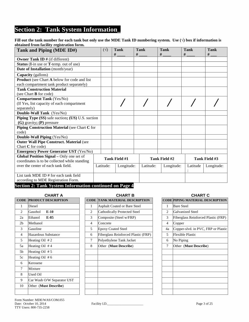
Section 2: Tank System Information__ Fill out the tank number for each tank but only use the MDE Tank ID numbering system. Use (√) box if information is obtained from facility registration form. Tank and Piping (MDE ID#) (√) Tank
# ____ Tank # ____
Tank # ____
Tank # ____
Tank # ___
Owner Tank ID # (if different) Status (I -in use or T-temp. out of use) Date of Installation (month/year)
Capacity (gallons) Product (see Chart A below for code and list each compartment tank product separately)
Tank Construction Material (see Chart B for code)
Compartment Tank (Yes/No) (If Yes, list capacity of each compartment separately)
⁄ ⁄ ⁄ ⁄ ⁄ Double-Wall Tank (Yes/No) Piping Type (SS) safe suction; (US) U.S. suction (G) gravity; (P) pressure
Piping Construction Material (see Chart C for code)
Double-Wall Piping (Yes/No) Outer Wall Pipe Construct. Material (see Chart C for code)
Emergency Power Generator UST (Yes/No) Global Position Signal – Only one set of coordinates is to be collected while standing over the center of each tank field.
Tank Field #1 Tank Field #2 Tank Field #3
Latitude: Longitude:
Latitude:
Longitude:
Latitude:
Longitude:
List tank MDE ID # for each tank field according to MDE Registration Form.
Section 2: Tank System Information continued on Page 4
CHART A CHART B CHART C CODE PRODUCT DESCRIPTION CODE TANK MATERIAL DESCRIPTION CODE PIPING MATERIAL DESCRIPTION
1 Diesel 1 Asphalt Coated or Bare Steel 1 Bare Steel
2 Gasohol E-10 2 Cathodically Protected Steel 2 Galvanized Steel
2a Ethanol E-85 3 Composite (Steel w/FRP) 3 Fiberglass Reinforced Plastic (FRP)
2b Methanol 4 Concrete 4 Copper
3 Gasoline 5 Epoxy Coated Steel 4a Copper-slvd. in PVC, FRP or Plastic
4 Hazardous Substance 6 Fiberglass Reinforced Plastic (FRP) 5 Flexible Plastic
5 Heating Oil # 2 7 Polyethylene Tank Jacket 6 No Piping
5a Heating Oil # 4 8 Other (Must Describe) 7 Other (Must Describe)
5b Heating Oil # 5
5c Heating Oil # 6
6 Kerosene
7 Mixture
8 Used Oil
9 Car Wash O/W Separator UST
10 Other (Must Describe)

Form Number: MDE/WAS/COM.055 Date: October 10, 2014 Facility I.D.______________________ Page 4 of 25 TTY Users: 800-735-2258
Section 2: Tank System Information (cont’d.)
Diagram: Show layout of site and all UST systems.
KEY/LEGEND (Include if applicable) Bollards (I ) Interstice (PS) Piping Sump (BLD) Building location Monitoring well (TF) Tank Field (CP) Cathodic protection test station (T #) Tanks (including all compartments) with MDE tank ID #s ↑ North arrow (P) Product piping ═╬ Roads bordering property (PS) Piping sumps (DB) Dry Break/Stage I vapor recovery (D) Dispenser (STP Sump) Submersible Turbine Pump (V) Vent pipe (ATG Probe) Automatic Tank Gauge (●) Tank field monitoring pipe (FP) Fill Pipe (ESO) Emergency Shutoff Switch (AN) Impressed current anodes
Form Number: MDE/WAS/COM.055 Date: October 10, 2014 Facility I.D._________________ Page 5 of 25 TTY Users: 800-735-2258
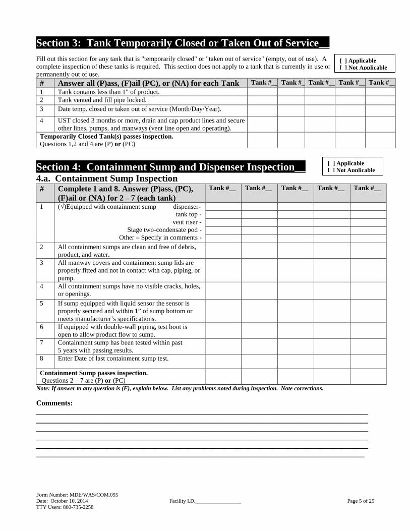
Section 3: Tank Temporarily Closed or Taken Out of Service___ Fill out this section for any tank that is "temporarily closed" or "taken out of service" (empty, out of use). A complete inspection of these tanks is required. This section does not apply to a tank that is currently in use or permanently out of use.
# Answer all (P)ass, (F)ail (PC), or (NA) for each Tank Tank #__ Tank #__Tank #__ Tank #__ Tank #__1 Tank contains less than 1" of product. 2 Tank vented and fill pipe locked. 3 Date temp. closed or taken out of service (Month/Day/Year).
4 UST closed 3 months or more, drain and cap product lines and secure other lines, pumps, and manways (vent line open and operating).
Temporarily Closed Tank(s) passes inspection. Questions 1,2 and 4 are (P) or (PC)
Section 4: Containment Sump and Dispenser Inspection__ 4.a. Containment Sump Inspection # Complete 1 and 8. Answer (P)ass, (PC),
(F)ail or (NA) for 2 – 7 (each tank) Tank #__
Tank #__
Tank #__
Tank #__ Tank #__
1 (√)Equipped with containment sump dispenser- tank top -
vent riser - Stage two-condensate pod -
Other – Specify in comments -
2 All containment sumps are clean and free of debris, product, and water.
3 All manway covers and containment sump lids are properly fitted and not in contact with cap, piping, or pump.
4 All containment sumps have no visible cracks, holes, or openings.
5 If sump equipped with liquid sensor the sensor is properly secured and within 1” of sump bottom or meets manufacturer’s specifications.
6 If equipped with double-wall piping, test boot is open to allow product flow to sump.
7 Containment sump has been tested within past 5 years with passing results.
8 Enter Date of last containment sump test.
Containment Sump passes inspection. Questions 2 – 7 are (P) or (PC)
Note: If answer to any question is (F), explain below. List any problems noted during inspection. Note corrections. Comments: ___________________________________________________________________________________________________________________________________________________________________________________________________________________________________________________________________________________________________________________________________________________________________________________________________________________________________________________________________________________________________________________________________________________________
[ ] Applicable [ ] Not Applicable
[ ] Applicable [ ] Not Applicable
Form Number: MDE/WAS/COM.055 Date: October 10, 2014 Facility I.D._________________ Page 6 of 25 TTY Users: 800-735-2258
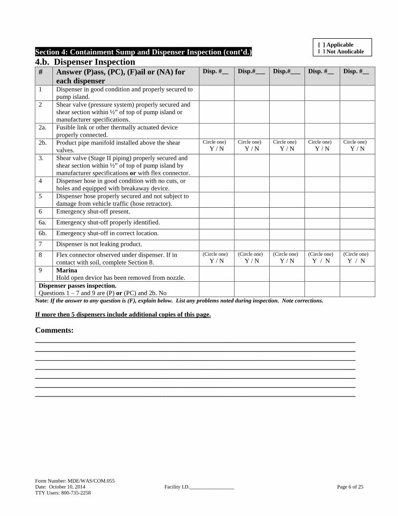
Section 4: Containment Sump and Dispenser Inspection (cont’d.) 4.b. Dispenser Inspection # Answer (P)ass, (PC), (F)ail or (NA) for
each dispenser Disp. #__
Disp.#___
Disp.#___
Disp. #__
Disp. #__
1 Dispenser in good condition and properly secured to pump island.
2 Shear valve (pressure system) properly secured and shear section within ½” of top of pump island or manufacturer specifications.
2a. Fusible link or other thermally actuated device properly connected.
2b. Product pipe manifold installed above the shear valves.
Circle one) Y / N
Circle one) Y / N
Circle one) Y / N
Circle one) Y / N
Circle one) Y / N
3. Shear valve (Stage II piping) properly secured and shear section within ½” of top of pump island by manufacturer specifications or with flex connector.
4 Dispenser hose in good condition with no cuts, or holes and equipped with breakaway device.
5 Dispenser hose properly secured and not subject to damage from vehicle traffic (hose retractor).
6 Emergency shut-off present.
6a. Emergency shut-off properly identified.
6b. Emergency shut-off in correct location.
7 Dispenser is not leaking product.
8 Flex connector observed under dispenser. If in contact with soil, complete Section 8.
(Circle one) Y / N
(Circle one) Y / N
(Circle one) Y / N
(Circle one) Y / N
(Circle one) Y / N
9 Marina Hold open device has been removed from nozzle.
Dispenser passes inspection. Questions 1 – 7 and 9 are (P) or (PC) and 2b. No
Note: If the answer to any question is (F), explain below. List any problems noted during inspection. Note corrections. If more then 5 dispensers include additional copies of this page. Comments: ______________________________________________________________________________________________________________________________________________________________________________________________________________________________________________________________________________________________________________________________________________________________________________________________________________________________________________________________________________________________________________________________________________________________________________________________
[ ] Applicable [ ] Not Applicable
Form Number: MDE/WAS/COM.055 Date: October 10, 2014 Facility I.D._________________ Page 7 of 25 TTY Users: 800-735-2258
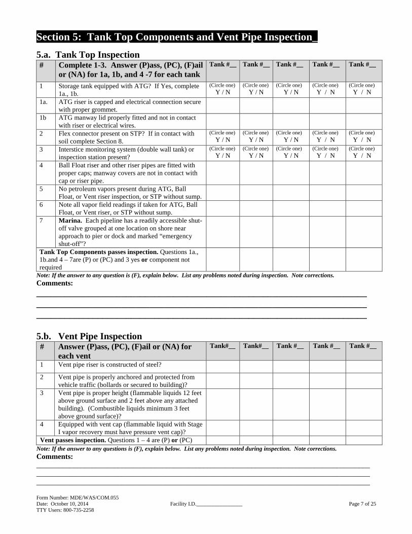
Section 5: Tank Top Components and Vent Pipe Inspection_
5.a. Tank Top Inspection # Complete 1-3. Answer (P)ass, (PC), (F)ail
or (NA) for 1a, 1b, and 4 -7 for each tank Tank #__
Tank #__
Tank #__
Tank #__ Tank #__
1 Storage tank equipped with ATG? If Yes, complete 1a., 1b.
(Circle one) Y / N
(Circle one) Y / N
(Circle one) Y / N
(Circle one) Y / N
(Circle one) Y / N
1a. ATG riser is capped and electrical connection secure with proper grommet.
1b ATG manway lid properly fitted and not in contact with riser or electrical wires.
2 Flex connector present on STP? If in contact with soil complete Section 8.
(Circle one) Y / N
(Circle one) Y / N
(Circle one) Y / N
(Circle one) Y / N
(Circle one) Y / N
3 Interstice monitoring system (double wall tank) or inspection station present?
(Circle one) Y / N
(Circle one) Y / N
(Circle one) Y / N
(Circle one) Y / N
(Circle one) Y / N
4 Ball Float riser and other riser pipes are fitted with proper caps; manway covers are not in contact with cap or riser pipe.
5 No petroleum vapors present during ATG, Ball Float, or Vent riser inspection, or STP without sump.
6 Note all vapor field readings if taken for ATG, Ball Float, or Vent riser, or STP without sump.
7 Marina. Each pipeline has a readily accessible shut-off valve grouped at one location on shore near approach to pier or dock and marked “emergency shut-off”?
Tank Top Components passes inspection. Questions 1a., 1b.and 4 – 7are (P) or (PC) and 3 yes or component not required
Note: If the answer to any question is (F), explain below. List any problems noted during inspection. Note corrections. Comments: __________________________________________________________________________________________________________________________________________________________________________________________________________________ 5.b. Vent Pipe Inspection # Answer (P)ass, (PC), (F)ail or (NA) for
each vent Tank#__
Tank#__
Tank #__
Tank #__ Tank #__
1 Vent pipe riser is constructed of steel?
2 Vent pipe is properly anchored and protected from vehicle traffic (bollards or secured to building)?
3 Vent pipe is proper height (flammable liquids 12 feet above ground surface and 2 feet above any attached building). (Combustible liquids minimum 3 feet above ground surface)?
4 Equipped with vent cap (flammable liquid with Stage I vapor recovery must have pressure vent cap)?
Vent passes inspection. Questions 1 – 4 are (P) or (PC) Note: If the answer to any questions is (F), explain below. List any problems noted during inspection. Note corrections. Comments: ______________________________________________________________________________________________________________________________________________________________________________________________________________________________________________________________________________

Form Number: MDE/WAS/COM.055 Date: October 10, 2014 Facility I.D._________________ Page 8 of 25 TTY Users: 800-735-2258
Section 6: Spill and Overfill
6.a. Spill Device # Answer (P)ass, (PC), (F)ail or (NA) Tank #__
Tank #__
Tank #__
Tank #__ Tank #__
1 Equipped with minimum 5-gallon catch basin. (Note: Used oil and heating oil USTs installed, upgraded, or replaced after 11-4-96 require catch basin).
2 Basin clean and free of debris and water.
3 Basin has no cracks or holes observed.
4 No abnormalities observed in fill pipe. (No bent drop tubes, no cracks or holes observed in basin especially at connection to tank and spill device).
5 Basin lid fits properly and not in contact with fill cap.
6 Fill pipe marked to indicate size of tank/type of product stored or Lid contains API color symbol w/posted sign to indicate tank size and type of product within delivery driver view.
7 Catch basin tested within past year with passing results in accordance with Maryland Containment System Testing Protocol.
7a. Date of last test: 8 Spill device not required: (Tank receives less than
25-gallons of petroleum per delivery or heating oil UST installed prior to 11-4-96 is not required to have a spill device). If not required indicate (P).
Spill device passes inspection. Questions 1 – 8 are (P) or (PC)
Note: If the answer to any question is (F), explain below. List any problems noted during inspection. Note corrections. Comments: ______________________________________________________________________________________________________________________________________________________________________________________________________________________________________________________________________________________________________________________________________________________________________________________________________________________________________________________________________________________________________________________________________________________________________________________________

Form Number: MDE/WAS/COM.055 Date: October 10, 2014 Facility I.D._________________ Page 9 of 25 TTY Users: 800-735-2258
Section 6: Spill and Overfill (cont’d.) 6.b. Overfill Device # Complete 2 – 4. Answer (P)ass, (PC), (F)ail or
(NA) for 1 and 5 – 9 Tank # ______
Tank # ______
Tank # ______
Tank # ______
Tank # ______
1 Fill drop tube required and observed.
2 Overfill device present (list all present): Flapper Valve (FV), Ball Float Valve (BFV), High Level Alarm (HLA), Other Describe.
3 Indicate delivery method–gravity (G) or pump flow (PF). 4 Owner/Operator ensures releases due to spilling or
overfilling do not occur? For example, product is measured prior to each delivery to ensure enough room in tank for product and all fuel deliveries are monitored.
(Circle one)
Y / N
(Circle one)
Y / N
(Circle one)
Y / N
(Circle one) Y / N
(Circle one) Y / N
5 Visually observed overfill device housing, documentation of installation provided, OR certification provided from a certified UST installer attesting to overfill device operability.
6 Tank receives less than 25-gallons of petroleum per delivery or heating oil UST installed prior to 11-4-96 is not required to have an overfill device.
7 Drop Tube Flapper Valve Visual observation indicated flapper valve is present, with no obstruction in the drop tube that would render the device ineffective. *
8 Ball Float Valve / Vent Restrictor Compatible with UST system configuration, delivery, and use. **
9 Audible External high level alarm only Visual and audible alarm present to the driver at the point of transfer.
Overfill device passes inspection. Question 4 is yes and 1 and 5– 9 (as applicable) are (P) or (PC)
Note: If the answer to any question is No (N) or (F), explain below. List any problems noted during inspection. Note corrections. *A fill pipe that utilizes a flapper valve in the drop tube for overfill purposes and receives a pressure delivery product drop, shall have a specific flapper valve designed for that use. ** If a UST system has one or more of the following, the owner or operator of the system shall not use a ball float valve on that system: (1) a tank that receives a pumped delivery; (2) suction piping with air eliminator; (3) remote fill pipes and gauge openings; (4) an emergency generator tank; (5) coaxial drop fill adapter. Comments: __________________________________________________________________________________________________________________________________________________________________________________________________________________________________________________________________________________________________________________________________________________________________________________________________________________________________________________________________

Form Number: MDE/WAS/COM.055 Date: October 10, 2014 Facility I.D._________________ Page 10 of 25 TTY Users: 800-735-2258
Section 7: Stage I and II Inspection____
Note: Stage I and II vapor recovery inspections also include completing and submitting Section 7c. forms to MDE’s Air and Radiation Management Administration. 7.a. Stage I Vapor Recovery # Complete 1 & 2 Answer (P)ass, (PC),
(F)ail or (NA) for 3 – 6a. for each tank Tank
#____ Tank #____
Tank #____
Tank #____
Tank #____
1 Is tank equipped with vapor recovery? (Yes) / (No) or (N/A). (If Yes for any tank, complete 2 through 6a. and section 7c.). Stage I required Statewide
2 Type of vapor recovery: A – Coaxial B – 2 point system
3 Dry break vapor cap and gasket in good condition?
4 Poppet valve in dry break moves easily and closes tight?
5 Vapor recovery connection equipped with minimum 5-gallon catchment basin. (If installed after July 1, 1998). (If 5 is N/A complete 5a. & 5b.).
5a. There are no petroleum vapors or staining in soil or pea gravel around vapor recovery riser pipe.
5b. Note all field readings if taken.
6 Catchment basin tested within the past year with passing results.
6a. Date of last test.
Stage I Passes Inspection. Question 1 is Y or NA and Questions 3 – 6a. are (P) or Stage I not applicable or (PC)
Comments: ______________________________________________________________________________________________________________________________________________________________________________________________________________________________________________________________________________
7.b. Stage II Vapor Recovery # Answer for each tank Tank
#_____ Tank
#_____ Tank #_____
Tank #____
Tank #____
1 Does the storage system have Stage II? Yes or No. (If Yes, complete 2 and 3 and Section 7c, If No and Stage II is decommissioned complete 4 - 4.b and 7c).
(Circle one)
Y / N
(Circle one)
Y / N
(Circle one)
Y / N
(Circle one)
Y / N
(Circle one)
Y / N
2 Type of vapor recovery: Balance System -(BS) Vacuum Assist -(VA)
3 UST system equipped with pressure control system and continuously monitors tank pressures.
Y / N Y / N Y / N Y / N Y / N
4 Stage II vapor recovery system decommissioned on all gasoline USTs? Y / N Y / N Y / N Y / N Y / N
4a. MDE Notification of Intent to Decommission or Not Install Stage II System form is available? Y / N Y / N Y / N Y / N Y / N
4b. Date of Stage II Decommission. (mm/dd/yy)
Stage II Passes Inspection. Question 1 is (Y) complete 2 or Question 1 is No and 4, 4a. and 4b. is complete or Stage II not applicable
Comments:_____________________________________________________________________________________________________________________________________________________________________________________________________________________________________________________
[ ] Applicable [ ] Not Applicable
[ ] Applicable [ ] Not Applicable

Form Number: MDE/WAS/COM.055 Date: October 10, 2014 Facility I.D._________________ Page 11 of 25 TTY Users: 800-735-2258
Section 7: Stage I and II Inspection (cont’d.) 7.c. Air and Radiation Management Administration Inspection Report (Submit completed copy of pages 11 & 12 to Air and Radiation Management Administration)
Maryland Department of the Environment Air and Radiation Management Administration
Suite 715, 1800 Washington Boulevard Baltimore MD 21230
410-537-3231 STAGE I AND II VAPOR RECOVERY SYSTEMS
INSPECTION REPORT
Owner: Operator/Lessee: Address: Address: Telephone: Telephone: Stage I Vapor Recovery System Condition of Fill:
Tank Vent Condition: Location, height, protected from traffic and weather? Yes � No �
Witness Fuel Drop: Yes � No � Fill and Vapor Swivel Adaptor Installed: Y � N � Comments:
Comments:
Stage II Vapor Recovery System Vapor Balance System / Vacuum Assist System (Circle One)
EQUIPMENT (No. Present) MANUFACTURER MODEL NUMBER Nozzles: Hoses: Dispensers: Date Stage II Installed: TEST REQUIREMENTS
Balance System Vacuum Assist System
Liquid Blockage: Pass � Fail � Date ____ Liquid Blockage: Pass � Fail � Date ___ Leak Test: Pass � Fail � Date ____ Leak Test: Pass � Fail � Date ___ Dynamic Back Pressure: Pass � Fail � Date ____ Air to Liquid Ratio: Pass � Fail � Date ___
Frequency Liquid Blockage: Every 5 years Notify the MDE in writing within 5 days of Dynamic Backpressure: Annually ANY TEST FAILURE, including pre-tests. Leak Test: Annually Air to Liquid Ratio: Annually Healy Vacuum Assist System: Model 400 - Nozzle Regulation Test: Pass � Fail � Date _____ Vapor Return Line Tightness Test: Pass � Fail � Date _____ Model 600 & 800 – Air to Liquid Ratio Test: Pass � Fail � Date _____ Vapor Return Line Vacuum Integrity Test: Pass � Fail � Date _____ Equipment Inspection (include description, i.e. good, ok, cracked hose, etc.) MPD #1 #5 #2 #6 #3 #7 #4 #8 Comments:
Comments:
* Operator must inspect equipment daily. Verify log is being kept.

Form Number: MDE/WAS/COM.055 Date: October 10, 2014 Facility I.D._________________ Page 12 of 25 TTY Users: 800-735-2258
Section 7.c.: Air and Radiation Management Administration Inspection Report RECORDKEEPING Operator shall keep daily inspection logs, test reports, permits, violation notices, Department correspondence, training records, and other relevant information on-site (5-year retention). Complete � Incomplete � Maintenance Records (2-year retention) Complete � Incomplete � Comments ________________________________________________________________________________ ________________________________________________________________________________ INSTRUCTIONAL SIGNS ("Do Not Top Off", "MDE Toll Free Number" 1-800-633-6101) Complete � Incomplete � Comments ________________________________________________________________________________ ________________________________________________________________________________ TRAINING CERTIFICATES One employee must be trained at an approved training course. This employee may assist in the training of other employees. Include the name on the Stage II training certificate in the Comments section. Complete � Incomplete � Comments _________________________________________________________________________________
_________________________________________________________________________________
STAGE II DECOMMISSIONING Has the site decommissioned the Stage II Vapor Recovery System? � Yes � No If “yes”, please list date of decommissioning (mm/dd/yy): If “yes”, enter the last date of the following tests (tests required upon decommissioning and annually after decommissioning): Pressure Decay Test (mm/dd/yy): Vapor Tie-In Test (mm/dd/yy): P/V Vent Valve Test (mm/dd/yy): Follow-up Required _______________________________________________________________________________________________________________________________________________________________________________________________________________________________________ ___________________________________________________________________________________________________________________________________________________________________________ Inspector Date ________________________ Vapor Recovery Questions? Call MDE Air and Radiation Management Administration at 410-537-3231

Form Number: MDE/WAS/COM.055 Date: October 10, 2014 Facility I.D._________________ Page 13 of 25 TTY Users: 800-735-2258
Section 8: Corrosion Protection A buried metal tank and piping (including fittings, flex-connectors, etc.) must be isolated from soil and cathodically protected. Commercial Heating Oil UST systems installed after March 15, 1985 require corrosion protection.
� Non-Metal Construction Material Answer (P)ass, (PC), (F)ail or (NA) for
each tank and pipe Tank #___
Pipe #___
Tank #___
Pipe #___
Tank #___
Pipe #___
Tank #___
Pipe ___
Tank #___
Pipe ___
1 Tank: Outer wall made of non-metallic material such as fiberglass or plastic jacket or coating. N/A N/A N/A N/A N/A
2 Pipe: Outer wall made of non-metallic material such as fiberglass or flexible plastic. N/A N/A N/A N/A N/A
Non-Metal Construction passes inspection. Questions 1 and 2 are (P) or (PC) Go to Section 9
# Check (√) type of corrosion protection for each tank and pipe, and answer (P)ass, (PC), (F)ail or (NA) for each tank and pipe
Tank #___
Pipe ___
Tank #___
Pipe ___
Tank #___
Pipe ___
Tank #___
Pipe ___
Tank #___
Pipe ___
� Galvanic Cathodic Protection (Tank and Piping) 3 Tank: CP on (sti-P3
®) tested within past 3 years and passed test in accordance with NACE Code of Practice Standard. If supplemental anodes were installed or added, complete 3a.
N/A N/A N/A N/A N/A
3a. UST CP tested annually. N/A N/A N/A N/A N/A
4 Pipe: CP tested within past year and passed test in accordance with NACE Code of Practice Standard.
N/A N/A N/A N/A N/A
5 Record of last two cathodic protection tests on file with Owner or Operator.
6 Cathodic protection system failure was inspected/repaired within 60 days of test.
Galvanic Cathodic Protection passes inspection. Questions 3 – 6 are (P) or (PC) or 6 (NA)
� Impressed Current Cathodic Protection (Tank and Piping) 7 Date impressed current system installed. (M/Y).
8 Assessment performed at 5-year intervals.
9 System has power and is turned on.
10 Hour meter present? If (Y) complete 11. (Circle one) Y / N
(Circle one) Y / N
(Circle one) Y / N
(Circle one) Y / N
(Circle one) Y / N
11 Record hours: 12 60-day inspection log is present and properly
filled out.
13 Tank tested within past year and passed test in accordance with NACE Code of Practice Standard.
N/A
N/A
N/A
N/A
N/A
14 Pipe tested within past year and passed test in accordance with NACE Code of Practice Standard.
N/A
N/A
N/A
N/A
N/A
15 Records available for last two Impressed Current Cathodic Protection tests.
16 Cathodic protection system failure was inspected/repaired within 60-days of test.
Impressed Current Cathodic Protection passes inspection. Questions 8&9 and 12–16 are (P) or (PC)
[ ] Applicable [ ] Not Applicable

Form Number: MDE/WAS/COM.055 Date: October 10, 2014 Facility I.D._________________ Page 14 of 25 TTY Users: 800-735-2258
Section 8: Corrosion Protection (cont’d.) Internally Lined Tank Tank
#___ Pipe ___
Tank #___
Pipe ___
Tank #___
Pipe ___
Tank #___
Pipe ___
Tank #___
Pipe ___
17 Documentation available and tank was less than 10 years old prior to installing liner.
N/A
N/A
N/A
N/A
N/A
18 Documentation available and internal inspection performed to determine tank is structurally sound and free of corrosion holes prior to installing impressed current cathodic protection and liner.
19 Site assessment performed before installing liner. 20 Date liner installed (Month / Year). 21 Date of last internal inspection. (Month / Year). 22 Internal inspection performed within 10 years of
installation and every 5 years thereafter.
Internal Liner passes inspection. Questions 17 – 19 and 22 are (P) or (PC)
Note: If the answer to any question in section 8 is (F), explain below. List any problems noted during inspection. Note corrections.
Comments: ________________________________________________________________________________________________________________________________________________________________________________________________________________________________________________________________________________________________________________________________________________________________________________________________________________________________________________________________________________________________________________________________________________________________________________________________________________________________________________________________________________________________________________________________________________________
IF A METALLIC TANK OR PIPE HAS NO CATHODIC PROTECTI ON NOTIFY MDE
OIL CONTROL PROGRAM AT 410-537-3442.
Form Number: MDE/WAS/COM.055 Date: October 10, 2014 Facility I.D._________________ Page 15 of 25 TTY Users: 800-735-2258
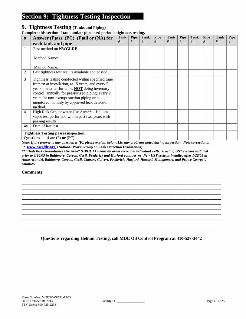
Section 9: Tightness Testing Inspection____
9. Tightness Testing (Tanks and Piping) Complete this section if tank and/or pipe used periodic tightness testing. # Answer (P)ass, (PC), (F)ail or (NA) for
each tank and pipe Tank #__
Pipe #__
Tank #__
Pipe #__
Tank #__
Pipe #__
Tank #__
Pipe #__
Tank #__
Pipe #__
1 Test method on NWGLDE . Method Name: Method Name:
2 Last tightness test results available and passed.
3 Tightness testing conducted within specified time frames: at installation, at 15 years, and every 5 years thereafter for tanks NOT doing inventory control; annually for pressurized piping; every 2 years for non-exempt suction piping or be monitored monthly by approved leak detection method.
4 High Risk Groundwater Use Area** – Helium vapor test performed within past two years with passing results.
4a. Date of last test.
Tightness Testing passes inspection. Questions 1 – 4 are (P) or (PC)
Note: If the answer to any question is (F), please explain below. List any problems noted during inspection. Note corrections. * www.nwglde.org (National Work Group on Leak Detection Evaluations)
**“High Risk Groundwater Use Area” (HRGUA) means all areas served by individual wells. Existing UST systems installed prior to 1/26/05 in Baltimore, Carroll, Cecil, Frederick and Harford counties or New UST systems installed after 1/26/05 in Anne Arundel, Baltimore, Carroll, Cecil, Charles, Calvert, Frederick, Harford, Howard, Montgomery, and Prince George’s counties.
Comments: ___________________________________________________________________________________________________________________________________________________________________________________________________________________________________________________________________________________________________________________________________________________________________________________________________________________________________________________________________________________________________________________________________________________________________________________________________________________________________________________________________________________________________________________________________________________________________________________________________________________________________________________________________________________________________________________________________
Questions regarding Helium Testing, call MDE Oil Control Program at 410-537-3442

Form Number: MDE/WAS/COM.055 Date: October 10, 2014 Facility I.D._________________ Page 16 of 25 TTY Users: 800-735-2258
Section 10: House Keeping and Monitoring Pipe/Well Inspection
10.a. Facility House Keeping # Answer (P)ass, (PC), (F)ail or (NA) 1 Facility is clean with no sign of spillage or open containers of oil.
2 ASTs (if present) are clean and properly maintained.
3 Pump island area is clean with no indication of surface spillage.
4 Garage area (if present) is maintained with no indication of surface spillage.
House Keeping passes inspection. Questions 1 – 4 are (P) or (PC) or (NA) Note: If the answer to any questions is (F), explain below. List any problems noted during inspection. Note corrections.
10.b. Tank Field Monitoring Pipes # Answer (P)ass, (PC), (F)ail or (NA) MP-1 MP-2 MP-3 MP-4 1 Storage systems installed after March 15, 1985 have PVC monitoring pipes
installed on opposing corners of the tank field.
1a. Gasoline storage systems installed after January 26, 2005 +>2,000-gallons or multiple tanks in a shared excavation used to fuel motor vehicles located in HRGUA* have four monitoring pipes (each corner of the tank field).
2 Monitoring pipes are screened to within 2ft. of the surface and the remaining 2ft. being solid pipe and sealed to prevent entrance of surface runoff.
3 Monitoring pipe has liquid-tight cap, protected from traffic with manhole cover and locked or bolted closed.
4 Monitoring pipe cover is clearly marked “monitoring well-do not fill” or identified using API color code symbol.
5 Monitoring pipes checked for the presence of petroleum contamination and if present complete 5a.
5a. Record product thickness if taken. Record field vapor reading if taken.
Site wells for Facilities located in HRGUA* Answer (P)ass, (PC), (F)ail or (NA) 6 Facility or immediate neighbor on either side supplied by
potable well? (Circle one) Y / N
7 Three or more groundwater monitoring wells installed outside of tank excavation area.
8 Monitoring wells have liquid-tight cap, protected from traffic with manhole cover and locked or bolted closed.
9 Groundwater has been sampled within past year and sample results available?
10 Site potable well has been sampled within past year.
Monitoring Pipes and Site Wells Pass Inspection. Questions 1 – 5 and 7 – 10 are (P) or (PC) or (NA)
Note: If the answer to any question is (F), explain below. List any problems noted during inspection. Note corrections. *“High Risk Groundwater Use Area” (HRGUA) means all areas served by individual wells. Existing UST systems installed prior to 1/26/05 in Baltimore, Carroll, Cecil, Frederick and Harford counties or New UST systems installed after 1/26/05 in Anne Arundel, Baltimore, Carroll, Cecil, Charles, Calvert, Frederick, Harford, Howard, Montgomery, and Prince George’s counties. Comments:
_____________________________________________________________________________________________________
_____________________________________________________________________________________________________
_____________________________________________________________________________________________________
_____________________________________________________________________________________________________
[ ] Applicable [ ] Not Applicable

Form Number: MDE/WAS/COM.055 Date: October 10, 2014 Facility I.D._________________ Page 17 of 25 TTY Users: 800-735-2258
Section 11: Inventory Control _
For metered storage systems: complete items 1 – 10. For non-metered storage systems: complete items 3 – 6. For tanks using Inventory Control combined with SIR: also complete Section 12d.
# Answer (P)ass, (PC), (F)ail or (NA) for each tank
Tank #_____
Tank #_____
Tank #_____
Tank #_____
Tank # _____
1 Readings recorded each day of operation.
2 Inventory records are reviewed daily and reconciled monthly. Note: Seven consecutive days of shortage totaling 80-gallons or more must be reported to owner and investigated.
3 Appropriate calibration tank chart is used for calculating volume to nearest 1/8 inch.
4 Stick readings recorded before and after each delivery.
5 Gauge stick is marked so the owner is capable of determining product level to the nearest 1/8 inch and stick is in good condition and not worn.
6 Stick capable of measuring full height of tank.
7 Monthly water readings checked to the nearest 1/8 inch and used in calculating inventory balances.
8 Prior 12 months of inventory data available.
9 Inventory variations do not exceed 1% + 130 gallons of the metered quantity (sales).
10 Existing inventory results show no evidence of a release, and no water intrusion.
Inventory Control Passes Inspection Questions 1 – 10 are (P) or (PC) or not applicable
If using Statistical Inventory Reconciliation (SIR), also complete Section 12.d. Note: If answer to any question is (F), explain below. List any problems noted during inspection. Note corrections. Comments: ___________________________________________________________________________________________________________________________________________________________________________________________________________________________________________________________________________________________________________________________________________________________________________________________________________________________________________________________________________________________________________________________________________________________________________________________________________________________________________________________________________________________________________________________________________________________________________________________________________________________________________________________________________________________________________________________________________________________________________________________________________________
[ ] Applicable [ ] Not Applicable

Form Number: MDE/WAS/COM.055 Date: October 10, 2014 Facility I.D._________________ Page 18 of 25 TTY Users: 800-735-2258
Section 12: Release Detection Summary____ This section indicates the method or methods of release detection present. Proceed to the section identified in the last column. Emergency power generator UST systems and heating oil (on-site consumptive use) UST systems are exempt from release detection.
Tank Method: Complete for each tank
Indicate primary (PR) method and, if applicable, secondary (S) method for each tank
If using as primary method, proceed to section:
Tank #___ Tank #____ Tank # ___ Tank #____ Tank #____
Automatic Tank Gauging
12.a.
Vapor Monitoring 12.b. Interstitial Monitoring 12.c. Statistical Inventory Reconciliation
12.d.
Groundwater Monitoring 12.e. Manual Tank Gauging 12.f. None needed (Explain) Skip section 12
Pipe Method: Complete for each pipe run
Indicate primary (PR) method and, if applicable, secondary (S) method for each pipe run
If using as primary method, proceed to section:
Pipe # _____
Pipe # _____
Pipe # _____
Pipe # _____
Pipe # _____
Pressurized piping only Automatic line leak detector (ALLD) will detect 3-gph release, double-wall pipe with containment sump and liquid sump sensor.
12.c. and 12.h.
ALLD will detect 3-gph release, double-wall pipe with containment sump and manual interstitial monitoring.
12.c. and 12.h.
Electronic ALLD will perform 3-gph continuous test plus 0.2-gph monthly test.
12.h.
Mechanical ALLD will detect 3-gph release in conjunction with annual line tightness test.
9 and 12.h.
Other combination: (Explain in comments) Suction piping only
Line tightness test every 2 years. 9
Double wall piping with containment sumps utilizing electronic or manual interstitial monitoring.
12.c.
Safe Suction. 12.g.
None needed (Explain) Skip Section 12
Comments: ____________________________________________________________________________________________________________________________________________________________________________________ ____________________________________________________________________________________________________________________________________________________________________________________ ____________________________________________________________________________________________________________________________________________________________________________________

Form Number: MDE/WAS/COM.055 Date: October 10, 2014 Facility I.D._________________ Page 19 of 25 TTY Users: 800-735-2258
Section 12: Release Detection (cont’d.)
Section 12.a. Automatic Tank Gauging (Tank Only)
# Complete 1 and 4. Answer (P)ass, (PC), or (F)ail for 2,3,5 – 10.
Tank #__ Tank #__ Tank #__ Tank #__ Tank #__
1 Console Make and Model Make:
Model:
2 Monitoring console is working.
3 Owner's manual for console and probes is available at site.
4 Frequency ATG performs test (D) daily, (W) weekly, or (M ) monthly.
5 Device is calibrated, operated, and maintained per manufacturer's instructions in addition to limitations listed on evaluation summary NWGLDE* list.
6 System setup reviewed and system capable of verifying probe(s) are functioning and documenting results.
6a. Attach copy of print out for the last monthly ATG tank leak test to this page.
7 Tank is filled to proper capacity and test run for proper duration of time for last 2 months per NWGLDE* list.
8 Verification that console and probe are third party approved and on the NWGLDE* list.
9 Monthly release detection records are available and reviewed for past 12 months.
10 Existing release detection results reviewed shows no failure.
ATG passes inspection.
Questions 2, 3 and 5 – 10 are (P) or (PC)
Note: If the answer to any question is (F), explain below. List any problems noted during inspection. Note corrections. *www.nwglde.org (National Work Group on Leak Detection Evaluations). Comments: __________________________________________________________________________________________________________________________________________________________________________________________________________________________________________________________________________________________________________________________________________________________________________________________________________________________________________________________________
[ ] Applicable [ ] Not Applicable

Form Number: MDE/WAS/COM.055 Date: October 10, 2014 Facility I.D._________________ Page 20 of 25 TTY Users: 800-735-2258
Section 12: Release Detection (cont’d.)
Section 12.b. Vapor Monitoring (Tanks and/or Piping) # Complete 1. Answer (P)ass, (PC),
(F)ail or (NA) for 2 – 11. Tank #___ Tank #___ Tank #___ Tank #___ Tank #___
1 Console Make and Model Make:
Model:
2 Monitoring panel and/or control box is working.
3 Verification that the Vapor Monitoring device is third-party approved and on the NWGLDE* list.
4 Owner's manual for the Vapor Monitoring device is available at the site.
5 The material used as backfill is sufficiently porous, such as pea gravel or sand, to readily allow diffusion of vapors from releases into the excavation zone.
6 Vapor Monitors are designed, calibrated, and operated to detect an increase in concentration of the regulated substance, a component of the regulated substance, or a tracer compound placed in the tank system and maintained per manufacturer's instructions in addition to limitations listed on evaluation summary NWGLDE* list.
7 Site evaluation report is on site and verifies the above information and that background contamination will not interfere with vapor monitoring. Attach evaluation cover page.
8 System setup reviewed and proper settings confirmed correct. Verification all probes functioning.
9 Vapor Monitors are checking portion of tank and piping that routinely contain product.
10 Monthly release detection records are available for last 12 months.
11 Existing release detection results show no evidence of a release.
Vapor Monitoring passes inspection.
Questions 2 – 11 are (P) or (PC)
Note: If the answer to any question is (F), please explain below. List any problems noted during inspection. Note corrections. * www.nwglde.org (National Work Group on Leak Detection Evaluations). Comments: ____________________________________________________________________________________________________________________________________________________________________________________ __________________________________________________________________________________________ __________________________________________________________________________________________
[ ] Applicable [ ] Not Applicable

Form Number: MDE/WAS/COM.055 Date: October 10, 2014 Facility I.D._________________ Page 21 of 25 TTY Users: 800-735-2258
Section 12: Release Detection (cont’d.)
Section 12.c. Interstitial Monitoring (Tank and Piping) # Complete 1 and 3 for Electronic and
Answer (P)ass, (PC), (F)ail or (NA) 2&4–10 for each Tank and Pipe
Tank # ___
Pipe # __
Tank # ___
Pipe #___
Tank #___
Pipe#___
Tank #___
Pipe #___
Tank #___
Pipe #___
1 Type of interstitial monitoring: i.e. Liquid (L), Air Space (AS), or Pressure/vacuum (PV). List each if different.
Manual /Visual Inspection Only 2 Interstitial space is monitored and a written log is
maintained monthly.
Electronic System Only 3 Console make/ model Make:
Model:
4 Console and sensor on NWGLDE* list
5 Monitoring console is operational.
6 Interstitial space monitored monthly. **
7 Device is calibrated, operated, and maintained per manufacturer's instructions in addition to limitations listed on evaluation summary NWGLDE* list.
Summary 8 Monthly release detection records are available for
prior 12 months with passing results.
9 No evidence of liquid in sump or interstitial space of air filled system. No evidence of loss or gain of brine in brine filled system. Operation of partial vacuum or over pressure system is within manufacturer’s design specifications.
10 No visible leaks or holes in secondary containment.
Interstitial Monitoring passes inspection. Questions 2 and 8 – 10 are (P) for Manual Questions 4 – 10 are (P) or (PC) for Electronic
Note: If the answer to any question is (F), please explain below. List any problems noted during inspection. Note corrections. **Monitor interstitial space at lowest point of secondary containment for air filled or at highest point of secondary containment for brine filled and is positioned so that other equipment will not interfere with its proper operation. See manufacture specifications and NWGLDE listing limitations for continual partial vacuum or overpressure interstitial monitoring.
*www.nwglde.org (National Work Group on Leak Detection Evaluations).
Comments: ______________________________________________________________________________________________________________________________________________________________________________________________________________________________________________________________________________________________________________________________________________________________________________________________________________________________________________________________________________________________________________________________________________________
[ ] Applicable [ ] Not Applicable
Form Number: MDE/WAS/COM.055 Date: October 10, 2014 Facility I.D._________________ Page 22 of 25 TTY Users: 800-735-2258
Section 12: Release Detection (cont’d.)
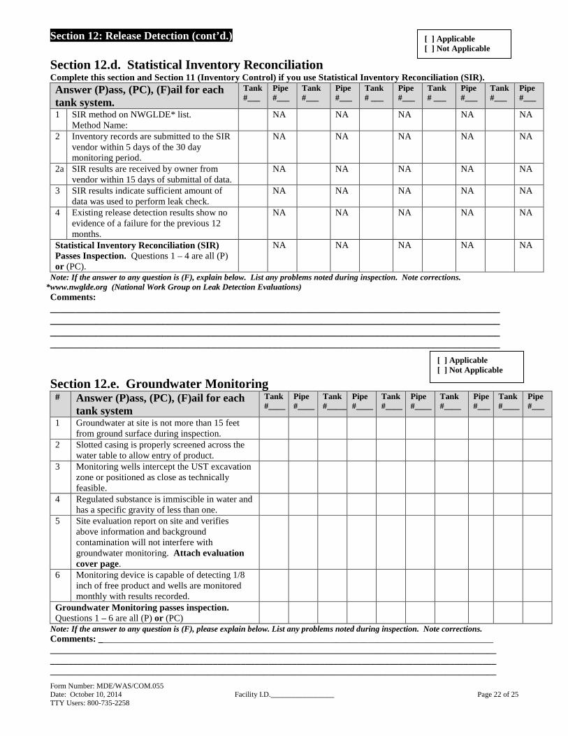
Section 12.d. Statistical Inventory Reconciliation Complete this section and Section 11 (Inventory Control) if you use Statistical Inventory Reconciliation (SIR). Answer (P)ass, (PC), (F)ail for each tank system.
Tank #___
Pipe #___
Tank #___
Pipe #___
Tank # ___
Pipe #___
Tank # ___
Pipe #___
Tank #___
Pipe #___
1 SIR method on NWGLDE* list. Method Name:
NA NA NA NA NA
2 Inventory records are submitted to the SIR vendor within 5 days of the 30 day monitoring period.
NA NA NA NA NA
2a SIR results are received by owner from vendor within 15 days of submittal of data.
NA NA NA NA NA
3 SIR results indicate sufficient amount of data was used to perform leak check.
NA NA NA NA NA
4 Existing release detection results show no evidence of a failure for the previous 12 months.
NA NA NA NA NA
Statistical Inventory Reconciliation (SIR) Passes Inspection. Questions 1 – 4 are all (P) or (PC).
NA NA NA NA NA
Note: If the answer to any question is (F), explain below. List any problems noted during inspection. Note corrections. *www.nwglde.org (National Work Group on Leak Detection Evaluations) Comments: ________________________________________________________________________________________________________________________________________________________________________________________________________________________________________________________________________________________________________________________________________________________________
Section 12.e. Groundwater Monitoring # Answer (P)ass, (PC), (F)ail for each
tank system Tank #____
Pipe #____
Tank #_____
Pipe #____
Tank #____
Pipe #____
Tank #____
Pipe #___
Tank #____
Pipe #___
1 Groundwater at site is not more than 15 feet from ground surface during inspection.
2 Slotted casing is properly screened across the water table to allow entry of product.
3 Monitoring wells intercept the UST excavation zone or positioned as close as technically feasible.
4 Regulated substance is immiscible in water and has a specific gravity of less than one.
5 Site evaluation report on site and verifies above information and background contamination will not interfere with groundwater monitoring. Attach evaluation cover page.
6 Monitoring device is capable of detecting 1/8 inch of free product and wells are monitored monthly with results recorded.
Groundwater Monitoring passes inspection. Questions 1 – 6 are all (P) or (PC)
Note: If the answer to any question is (F), please explain below. List any problems noted during inspection. Note corrections. Comments: _____________________________________________________________________________________ ________________________________________________________________________________________________________________________________________________________________________________________________________________________________________________________________________________________________
[ ] Applicable [ ] Not Applicable
[ ] Applicable [ ] Not Applicable

Form Number: MDE/WAS/COM.055 Date: October 10, 2014 Facility I.D._________________ Page 23 of 25 TTY Users: 800-735-2258
Section 12: Release Detection (cont’d.)
Section 12.f. Manual Tank Gauging (Tank Only)
# Answer 1– 5 (P)ass, (PC), (F)ail or (NA) for each Tank
Tank #__ Tank #__ Tank #__ Tank #__ Tank #__
1 Tank is 550-gallons or less.
2 Tank is 551 to 2,000-gallons. Note: Must be combined with tightness testing.
3 Gauging stick is capable of measuring the full height of the tank to the nearest 1/8” in conjunction with the appropriate tank calibration chart on site.
4 Monthly log is maintained. *
5 Last 12 months of records show no failure.
Manual Tank Gauging passes inspection.
Questions 1 or 2 and 3–5 are (P) or (PC)
Note: If the answer to any question is (F), explain below. List any problems noted during inspection. Note corrections. * See Inspector guidance book or COMAR 26.10.05.04C. for weekly and monthly variation standard. Comments:___________________________________________________________________________________________________________________________________________________________________________ __________________________________________________________________________________________
Section 12.g. Safe Suction (Suction Piping Only) # Answer (P)ass, (F)ail, or (PC) for
each pipe Pipe
#____ Pipe
#____ Pipe
#____ Pipe
#____ Pipe
#____ 1 The piping slope is back to the tank and
operates under atmospheric pressure or less.
2 Confirm a single check valve is located directly under the dispensing pump.
Safe Suction passes inspection. Questions 1 and 2 are (P) or (PC)
Note: If the answer for 1or 2 is (F), another type of release detection must be used and inspected. Fill out the applicable section on piping release detection. List any problems noted during inspection. Note corrections. Comments:____________________________________________________________________________________________________________________________________________________________________________________________ ______________________________________________________________________________________________________________________________________________________________________________________________________
Section 12.h. Automatic Line Leak Detectors (Pressurized Piping Only)
# Complete 1 Answer questions 2 – 7 (P)ass, (F)ail or (PC)
Pipe # #____
Pipe # #____
Pipe #____
Pipe #___
Pipe # ___
1 Mechanical or Electronic (M - Mechanical or E - Electronic)
2 Is the equipment on the NWGLDE* list.
[ ] Applicable [ ] Not Applicable
[ ] Applicable [ ] Not Applicable
[ ] Applicable [ ] Not Applicable

Form Number: MDE/WAS/COM.055 Date: October 10, 2014 Facility I.D._________________ Page 24 of 25 TTY Users: 800-735-2258
Section 12: Release Detection (cont’d.) 3 All ALLDs pass an annual field operability
test for detection of a 3.0-gph leak.
4 Device is calibrated, operated, and maintained per manufacturer's instructions in addition to limitations listed on evaluation summary NWGLDE* list.
5 Line Leak Detector shows no evidence of a visual release.
6 Is the entire piping system covered by the ALLD (including satellite pipe if present)?
7 For an electronic ALLD, last record of passing 3.0-gph test result for each pipe is within the previous 72 hours.
8 Does the STP shut off when the dispensers are not pumping?
ALLD Passes Inspection. Questions 2 – 8 are (P) or (PC)
Note: If the answer to any question is (F), please explain below. List any problems noted during inspection. Note corrections *www.nwglde.org (National Work Group on Leak Detection Evaluations) COMMENTS: _______________________________________________________________________________ ________________________________________________________________________________________________________________________________________________________________________________________
Section 13 Suspected Release Answer (Y)es or (N)o for 1 and if yes answer 2
1 Do you suspect or have you detected a release during this inspection?
[ ] Yes [ ] No
2 Did you report this suspected or detected release to the Department?
[ ] Yes [ ] No DATE: TIME:
GENERAL COMMENTS: _______________________________________________________________________________________________________________________________________________________________________________________________________________________________________________________________
Inspector’s Initials: _______ Owner/Operator’s Initials: ________ Date: _________ _____ Date: _____________
Report all known or suspected spills or leaks Call Maryland Department of the Environment 410-537-3442
Or call: 1-866-633-4686 after business hours
Form Number: MDE/WAS/COM.055 Date: October 10, 2014 Facility I.D._________________ Page 25 of 25 TTY Users: 800-735-2258
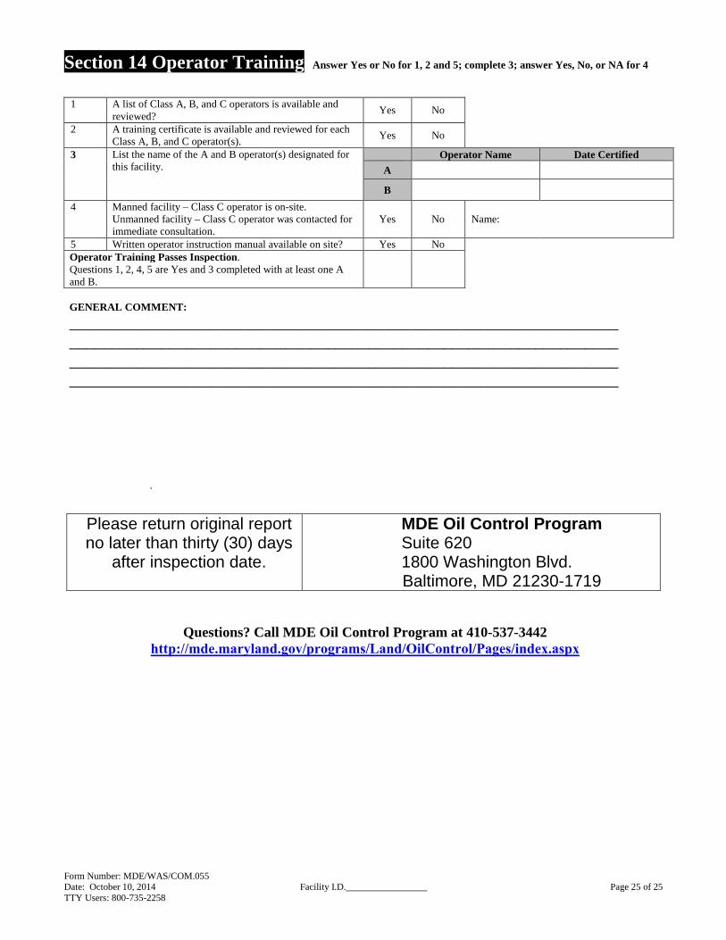
Section 14 Operator Training Answer Yes or No for 1, 2 and 5; complete 3; answer Yes, No, or NA for 4
1 A list of Class A, B, and C operators is available and reviewed?
Yes No
2 A training certificate is available and reviewed for each Class A, B, and C operator(s).
Yes No
3 List the name of the A and B operator(s) designated for this facility.
Operator Name Date Certified
A
B
4 Manned facility – Class C operator is on-site. Unmanned facility – Class C operator was contacted for immediate consultation.
Yes No Name:
5 Written operator instruction manual available on site? Yes No Operator Training Passes Inspection. Questions 1, 2, 4, 5 are Yes and 3 completed with at least one A and B.
GENERAL COMMENT:
________________________________________________________________________________________________________________________________________________________________________________________________________________________________________________________________________
.
Questions? Call MDE Oil Control Program at 410-537-3442 http://mde.maryland.gov/programs/Land/OilControl/Pages/index.aspx
Please return original report no later than thirty (30) days
after inspection date.
MDE Oil Control Program Suite 620 1800 Washington Blvd. Baltimore, MD 21230-1719