Embed Size (px)
Citation preview

1 | P a g e

2 | P a g e
ACKNOWLEDGEMENT
I am thankful to my supervisor Dr. Jerard J Gouw for giving me a real life project to work on
Ergonomic design of a car seat. This project definitely helped me to gain better learning and
understanding of different type of seating position and its impact on human comfort and injury. I
would also like to thank him for rendering all his efforts, supports and encouragement to complete the
project.

3 | P a g e
ABSTRACT
Passenger car seating design and arrangement for driver plays significant role on drivers comfort and
safety while driving. Most drivers are in a high-risk group for spinal disorders including back pain,
neck pain, sciatica, degeneration, and herniated discs, etc. A proper ergonomics design can solve these
problems or reduced the problem significantly, therefore as an engineer we must have to know about
the structure of the vehicle seat. It is necessary to establish ergonomic models of the seating and
analyze the position of the segments of the body when the driver holds a posture of driving.
This project based on popular software CATIA V5 and provides details on human builder and human
measurements components. Major role of the software is to create mankind with different percentile
using Human Builder and Human Measurement Workbench with additional analysis of different
posture. Before designing and analyzing an ergonomic car seat its prime need to design a 3D model of
mankin with necessary view which explains work activities with different posture, including reach
envelop, vision analysis and posture activity. Additionally; and ergonomic car seat and steering wheel
also modeled and assembled with the design. Furthermore; apart from the software recent
technological aspect to design an ergonomic car seat also discussed and analyzed. Based on necessity
and habit, most of the cases a driver is bound to drive a car for long time, therefore because of long
term sitting movement of different body segments such as hand, forearm, leg and eyes are affected
which are the cause of light injuries and affected the task of driver. Because, the postures should be
studied in the research and the designer of the vehicle seat should emphasized on it. The position of
the segment of the body of the driver in driving is also an important parameter in the design of the
vehicle seat. It decides the dimension of the seat and makes the seat more comfort and can be used by
the 95 percent people. An ergonomic seat also designed and compared with flat type back seat. The
result shows ergonomic seat has less impact in trunk than regular seat.

4 | P a g e
TABLE OF CONTENTS
Section Title Page 1. Introduction and Literature Review …………………………………………………. 01
1.1 Ergonomics In The Automotive Industry ………………….…………..….….. 02 1.2 Standards, Guidelines And Recommendations …………..……………………. 02 1.3 Anthropometry And Fundamental Fallacies ………………..……….…………. 03 1.4 Seat Feature Design Assessment ……………………………………………….. 04 1.4.1 Road Test ……….……………………………………………..…………. 05 1.4.2 Simulation ………………………………………………………..……… 05 2 Design Consideration …………………………………………………….…………. 06 3 Designing Passenger Car Seat Travel ………………………………………..……… 06 4 Model Development, Analysis and Discussion ……………..……………..……….. 09 4.1 Create Mankin ……………………………………………………..…………. 10 4.2. Create Different % Ile Mankin …..……………………………………….…... 10 4.3. Steering Wheel Design …..………………………………………………….... 11 4.4. Chair Design ……..…………………………………………………………… 11 4.5. Human Measurement Edition ..………………….……………………………. 12 4.6. Load Parameters ………………………………………………………………. 13 4.7. Create Constraint ……………………………………………………………… 14 4.8. Posture Editor ……………………………………………….………………… 15 4.9. Angular Limitations To Percentage Setting …………………………………… 16 4.10. Object Attachment With The Mankin ………………………………………… 17 4.11 Mankin Reach Envelop ……………………………………………………….. 18 4.12 Inverse Kinematics (IK) ………………………………………………………. 19 5 Ergonomic Analysis ………………………………………………………………… 20 5.1. Vision Analysis ………………………………………………….................... 20 5.2 RULA Analysis using CATIA ………………………………………………… 21 5.2.1. Setting Ergonomics Analysis in CATIA ……………………….. 22 5.2.2. Perform RULA Analysis ……………………………………… 22 5.2.3.1 Posture Related to RULA Analysis …………………... 23
6 REBA Analysis ………………………………………………………………………. 24 7 Biomechanics Single Action Analysis ……………………………………………… 25 7.1. Biomechanics Analysis Result ………………………………………………… 26 8 Comparing Ergonomic And No Ergonomic Seat Effects On Trunk …………….….. 28 9 Some Recommendations Of Correct Sitting, Seat Design And The Drivers …..…… 29 10 Discussion ………………………………………………………..…………..…….. 31 11 Conclusion ………………………………………………………..…………..…….. 32 12 References ……………………………………………………………………..……. 33

5 | P a g e
LIST OF FIGURE
FIGURE No SHORT TITLE PAGE NO
1 Experimental Driving Rig 5
2-4 Seat Travel Distance 6-7
5-8 Mankin 9-10
9 Steering Wheel Design 10
10-12 Chair Design 10-11
13-16 Human Measurement 12-13
17-19 Load Definition 13-14
20-23 Posture 15-16
24 Angular Limitation 17
25-30 Object Attachment 17-18
31 Reach Envelop 19
32 Inverse Kinematics 19
33-34 Vision Analysis 20-21
35-37 RULA Analysis 21-22
38 REBA Analysis 24
39 Biomechanics 27
41-42 Comparing Correct Seating 30
43-44 Recommendation of Seating 31
LIST OF TABLE
TABLE No SHORT TITLE PAGE NO
1 Result Of Summary Data Tab 28
2 Result of Joint Moment Strength Data Tab 28
3 Result of Segment Positions Tab 28
4 Result of Reaction Forces And Moments 29

1 | P a g e
1. INTRODUCTION AND LITERATURE REVIEW
Ergonomics has a wide application in human society nowadays. Humans need more comfortable
environment of living and safer working condition. The goal to apply ergonomics technology on the
design of the equipments and systems is to ensure humans with them in complete harmony. So
engineers always put ergonomics in the more important position in the design. The purpose of this
project is to develop a CATIA tutorial to make a full human activity analysis in a sitting position of
vehicle driver. This project deals with developing a step by step CATIA tutorial explaining how the
Ergonomic Design and Analysis module along with its Human Builder and Human Measurements
components are used for creating a manikin with different percentile while changing joint angles
reflecting postural change. These changed postures are then viewed in different planes including in 3D
and analyzed for the driving activity which must include viewing at the display terminal while sitting
on a driving sit.
Firstly, a model is realized using the Human Builder tool available in Ergonomics Design and
Analysis. The model is then tailored to different percentiles using Human Measurements components.
Secondly, two major different percentile models are studied in a step by step tutorial form for their
different postures performing the driving vehicle. The study here means the information generated by
CATIA corresponding to a particular posture of particular model are gathered and observed carefully
to see whether any sitting position for driver performed over a long period of time per day could cause
any health injury resulting from awkward posture.
Finally; the driver can adjust the height of the seat and the angle of the rest back and also can move the
seat along the sliding rack to let it to suit the different size of the drivers. The position of the segments
of the body and posture of driving are most important parameters that the designer should consider and
designed the seat based on the posture so that it can provide a good lumber support of driver. From the
above parameters the designer can find the best posture to reduce the risk of the ergonomic problem
significantly.

2 | P a g e
1.1 ERGONOMICS IN THE AUTOMOTIVE INDUSTRY
Tools and techniques used by ergonomists in the automotive industry are based on statistical data, Test
drive, and Simulation and computer software. Statistical data analysis and test drive are the primitive
but not considered that much in now a days. In case of simulation and computer software they are
using the same data sources and CAD tools and some simulative hardware. Simulative hardware runs
user trials to evaluate their products; in some cases using only company staff as subjects, in other cases
with members of the general public. They have good correspondence with universities and the
organization is involved in research projects. Normally if there are no ergonomists then the data
sources considered as out of date and user evaluations are rarely conducted. Overall Ergonomics
evaluation depends on the quality of product and the price therefore only few model cars come with
proper ergonomic design of car seat.
1.2 STANDARDS, GUIDELINES AND RECOMMENDATIONS [3]
Many areas of ergonomics those are pertinent to automotive design. In case of occupant
accommodation there is wide range of standards, guidelines and recommendations available those are
extremely useful in the early stages of concept design because they are readily available. Some of the
major giant company use their own or modified standard. Some of the standards and their associated
procedures have already been developed or in developing process in the field of ergonomics. USA:
The Society of Automotive Engineers (SAE) has been particularly active in the generation of such
Standards and many of these form part of the legislation which covers automotive design. In case of
human body parts with their relevant posture SAE recommendation to Ergonomist are give below: SAE J826 H-point (ISO 6549) SAE J1100 Seating reference point SAE J1100 H-point travel path SAE J1517 Driver selected seat position SAE J941 Eye llipse (ISO 4513/BS AU 176) SAE J1052 Driver and Passenger head position contours SAE J287 Hand controls reach envelopes (ISO 4040/BS AU 199)

3 | P a g e
1.3 ANTHROPOMETRY AND FUNDAMENTAL FALACIES [3 ]
Design and development of vehicles still now many automotive companies did not have a formalized
structure to identify and deal with ergonomics issues. The main reason behind this is several
misconceptions about ergonomics and lack of knowledge to justify the necessity of it. Pheasant (1996)
and Porter and Porter (1997) in their own experience found that ergonomics in automobile industry
eight fallacies exist to design and implement a product.
1. Ergonomics is expensive and since products are actually purchased on appearance and styling,
ergonomics considerations may conveniently be ignored.
2. The design is not satisfactory for me – it will, therefore, be unsatisfactory for everybody else (a
variation on fallacy 1 above).
3. Percentiles are a very clear and simple way to present and use information concerning body size.
1-3 Fallacies is ignored because we are designing ergonomics sitting.
4. The design is satisfactory for me – it will, therefore, be satisfactory for everybody else.
Not recommended fallacies for this project because the design should fit wide range of people.
5. This design is satisfactory for the average person – it will, therefore, be satisfactory for everybody
else.
Not recommended fallacies for this project because unfortunately for automotive designers, there is no
such thing as an average man or woman, or child for that matter.
6. The variability of human beings is so great that it cannot possibly be catered for in any design – but
since people are wonderfully adaptable it doesn’t matter anyway.
Not recommended fallacies for this project because though we know people are adaptable but we have
to does research has to come up with result that meet requirement for most people.

4 | P a g e
7. Ergonomics is an excellent idea. I always design things with ergonomics in mind, but I do it
intuitively and rely on common sense so I don’t need tables of data.
Not recommended fallacies for this project because manual design without using table and standard
data may not fulfill all the requirement of ergonomics car seat design.
8. Designing from 5th percentile female to 95th percentile male dimensions will accommodate 95%
of people.
Recommended and considered fallacies for this project. This will be true if only one dimension is
relevant to the design solution. However, some vehicle requires simultaneous accommodation on a
large number of dimensions because of lot of extra features than regular vehicle. There are poor
correlations between body dimensions it follows that those males who are designed out because of
limited headroom will not necessarily be the same 5% who are designed out for having arms that are
too long or the 5% with legs that are too long, hips too broad etc. Similarly, those females who are not
considered in design their relevant data too small will not just constitute 5% of the females. Therefore
5th percentile stature is a value whereby 5% of the population are shorter and 95% are taller; 50th
percentile stature is the median stature.
Finally; depending on the situation higher and median value conceded for this for this project. For
example, In case of car height definitely we have to consider the highest value of mankin therefore; we
must have to consider 95% ile male height.
1.4 SEAT FEATURE DESIGN ASSESMENT [3]
In case operation of a seat and drivers comfort, visual requirement and correct posture depends on
optimum design. A good design does not necessarily make sure that the design is correct in terms
drivers ergonomic requirement until it’s not tested or assessed .To asses a design it a challenge for
manufacturer because the result come from mass group of driver after a certain period of use.
Therefore; design should be tested very accurately before marketing. Most cases testing can be
performing by two major ways: 1. Road test 2. Simulation

5 | P a g e
1.4.1 ROAD TEST
One of the experiments of road test conducted by Porter and Gyi (1998) [3]. According to the Vehicle
Ergonomics Group instruction they performed two test videos of 2.5 hour (60 mile) drive in their road
trials. During this test they give driver’s view of the road, with a voice-over of instructions about the
route to guide the driver of when to change gear, slow down other driving instruction. After driving
they collect necessary data from drivers. In this way mental and physical effect of driver can be
assessed before and after the test.
1.4.2 SIMULATION
Another ways the car manufacturer tests a design by simulation. To accomplish this: Porter and Gyi
(1998) [3] used a highly adjustable driving rig (Figure 01) to identify driving postures and its effects
on a family type driving car. The simulation carried out to obtain the preferred driving
An Experimental Driving Rig.
posture of driver. For this with respect to the
seat they vary the height and horizontal
location of the steering wheel and pedals.
The seat tilt angle was also adjustable. For
each of these adjustments the component
travelled by the experimenter at discrete
increments throughout its range of travel
from one extreme to the other. Then they
temporarily fixed the component and back
again the adjustment in a balanced order
and perform the test again and again to achieve a satisfactory position. Until get a satisfactory result
they fine tuned the adjustment of all controls and positions again and again. Each adjustment a 10–15
minute driving simulation at the rig was then carried out to further confirmation that this posture was
optimum. Each result they document the relevant measures regarding the positions of the controls
from a fixed reference point. To get accurate result they placed the hands on the steering wheel and
Figure - 01

6 | P a g e
looking ahead as though they were driving on a road and partially depressing the accelerator. Each
instance of driving posture then measured. They have taken lot of care when using such data for
individual joints and their correlation with the trunk-thigh and knee angles.
2. DESIGN CONSIDERATION
To perform design we have to assume some factors that are given below:
• During turning of steering wheel, posture of driver was not considered because it happens for
few instances not even 1 turn/min.
• Consider automatic type of car therefore drivers left leg in rest position.
• Car roof height is not considered for design.
• Other minor posture for few instance changes like signal light on/off, Operating Air
conditioner/Radio, Changing gear etc not considered.
• Symmetric data considered for symmetric body parts.
The above design considerations happens only very few instance/minute therefore the driver posture
assume as static all the time and that will not affect any significant factors for design.
3. DESIGNING PASSENGAR CAR SEAT TRAVEL [1]
In case of vehicle seating configuration it’s a challenge for car manufacturer to meet the requirement
of wide range of people. The driver’s seat can move forward and backward. Apart from the driver’s
height, drivers seating habit is also important. Fig - 02 is typical configuration of vehicle seat. In the
figure The dimensions F,S,T,G varies a little with car manufacturer. We assume some standard value to
for those for design to find out seating position other important dimension. Some driver likes to seat
far away as possible from gas/brake pedal and some drivers likes to seat close to the gas/brake pedals.
Since we consider 95% ile Canadian male for the design therefore; now we are trying to find out the
seating configuration for them.

7 | P a g e
Assume
Standard Dimension for :
Dash board height F = 32 cm.
Steering Wheel Distance from
Dashboard S = 10 cm
Seating height from Base T = 27 cm.
Fully Pushed and Released Pedal Distance G = 10 cm. Based on the above information, we are going
to determine the follow distances for our design for 95% ile Canadian male:
• A = H2 – H1 = horizontal travel of the seat
• B = H1 – P1 = horizontal distance between the furthest forward position of the hip joint and the
fully pushed pedal
C = vertical distance between the
floor and the bottom of the
dashboard
D = horizontal distance between the
fully pushed pedal and the steering
wheel
Dimension no 15 : K = 460 mm
(95% ile Canadian Male)
2 22 605 270 541.41X mm∴ = − = Foot Length F = 290 mm (95% ile Male)
Page 1-5 Joint 18 : Ankle flexion (plantar flexion) 95% ile Male is = 580
3 2 1 2 3cos18 290 cos 58 153.67 555 541.41 153.67 1250.08X F mm H X X X mm∴ = = = = + + = + + =
2 1 1250.08 1021.65 228.43A H H mm∴ = − = − =
E
C
F
G
D
B A
S
T
H1
P2P1
H2
270 mm
X X X
K=460 mm
18°/
58°
3 2 1
Figure - 02
Figure - 03

8 | P a g e
B = Distance between furthest forward position of the hip joint and fully pushed pedal.
( )1021.65 10 10 1121.65 1122B mm mm∴ = + × = →=⎡ ⎤⎣ ⎦
C = Vertical distance between the floor and the bottom of dashboard. Consider the dashboard height
from bottom seat then its equivalent to the 1.5 times of hip joint height at sitting position from
SRP. Therefore; Segment 14 Hip above SRP
= 4.3” (Male and Female average link length) = 4.3”x25.4 mm = 109.22 mm
1.5 27 10 1.5 109.22 433.83C Height of the seat hip joint height mm= + × = × + × =
D = Horizontal distance between the fully pushed pedal and the steering wheel. [Assume that the hand
griping the steering wheel has a posture of the lower arm making angle of 900 with the upper arm]
The Length of average upper arm [page 1-6 segment 1 Man] = 17.4” = 17.4x25.4 mm= 441.96 mm
The Length of average lower arm [page 1-6 segment 2 Man] = 15.6” = 15.6x25.4 mm = 396.24 mm
Figure - 04 Here D = B-X
1250.8+(10x10)-593.57 = 757.23 mm [for Men]
WHERE
[ ]2 2441.96 396.24 593.57X mm for Men= + =
The final Dimension for 95 % ile Canadian
male are :
A =228.43 mm = 23 cm B = 1121.65
mm = 113 cm D = 757.23 mm = 78 cm
We will implement the dimension of A, B and D in CATIA for the design of car seat and Mankin
driving posture.
D
B
P1
X
Lower arm
Upper arm
Figure - 04

9 | P a g e
4. CATIA MODEL DEVELOPMENT, ANALYSIS AND DISCUSSION. [2]
4.1 CREATE MANIKIN
1. After Loading CATIA, then go to the start
menu, select Ergonomics design &
Analysis work bench and then click
Human Builder.
2. Human Builder work bench select insert
manikin icon located top of Human
Builder Sub Toolbar,
3. The Manikin Dialog Box appears which
consist of two tabs: Manikin and Optional. In
mankind tab Select Father product : In this
case the name is – Product_Maruf. The name
of mankin is ‘Driver’ and select 95% Male as
it described before on this selection.
4. From the ‘Optional’ tab select Canadian as
population and “Whole Body” Model with ‘H-
Point’ Referential. More option available eye
point, right foot, H-Point (default), Left foot,
lowest foot, and Crotch but whole body is
selected because this project intention to
analysis the whole body for a driver.
Figure : 5
Figure : 6
Figure : 7

10 | P a g e
4.2. CREATE DIFFERENT % ILE PERCENTILE MANIKIN
Although chosen 95% ile
Canadian male for design
and analysis but 10% ile
Canadian Female driver also
created to learn how to
implement different % ile in
same model. The
procedures are same but we
have to choose the Shuttle
icon to separate
manikin in different place,
as requirement of the
Project. Also need to
maintain height of all % ile
mankin based on Foot as
shown in figure. Finally: I
choose 95th percentile
Canadian man manikin.
Two different kind of Mankin – 95% Canadian Male and 10% Canadian Female.
4.3. STEERING WHEEL DESIGN
The most important part of steering wheel design are Wheel
Diameter and Rod Diameter. It depends on vehicle. The
standard value of Diameter of Wheel varies 325-400 mm and
Rod diameter varies 60-120 mm. Figure – 09 Wheel
Diameter considered 350 mm and Rod Diameter considered
75 mm. Other features do not have effect on human posture
therefore not considered in design.
Figure : 08
Figure : 09

11 | P a g e
4.4. CHAIR DESIGN
Figure –10 design of ergonomic back seat which is
designed for perfect lumber support of mankin. The
dimension of each curve designed in such a way that it is
exactly aligns with thoracic and lumber of 95%
Canadian male mankin. But in case of shorter driver of
5% female Canadian driver the seat back can be adjusted
up and down to get a good posture of lumber and
thoracic. Similarly Figure –11 design of ergonomic seat
base which also designed for perfect thigh support.
Figure -12 Complete Design of
Ergonomic seat with static
posture. Here thickness portion
of the back seat stay over the seat
bottom. Therefore; shorter
Driver(Female 5%) need to
adjust the head set only to get
the posture but won’t be able to
get good lumber support
compare to male 95% because of
height. So an alternative design
needed for shorter driver which
we try to find out after the
biomechanical analysis.
Figure : 10
Figure : 11
Figure : 12
Complete Design of Mankin with Static Driving posture of Mankin.
Horizontals Travel Distance A = 230 mm (Calculated Section-3 Page – 8)

12 | P a g e
4.5. HUMAN MEASUREMENTS EDITION
Human Measurement of different body parts which are related to create posture is available in Human
Measurements Edition work Bench. To perform the operation selects Icon and the manikin from
the specification tree. After that select the Display the variable list icon which display the list of
different body parts as shown in figure. Those body parts with the dimension generated automatically
based on the % ile chosen before. We don’t need to edit since we already select 95% ile Canadian male
for our project. But in mixed or different case when exact data are not available then according to the
design requirement we can easily EDIT any dimension by selecting the segment length and Select
‘Management - Manual’. The Figure – 13 provides dimension in standing position. The Figure – 14
Relevant data of Figure 13
To get the Figure – 13 click posture editor which will provides dimension in sitting
position. Although all dimension are automatic but in this project sitting
dimensions are the most important factors then standing because the project
Figure : 13
Figure : 14

13 | P a g e
is based on sitting position. Major posture of a Driver while driving: Figure -15 and Figure -16.
1. VISION –Line of Sight of driver. Related body parts – Eyes, Head and Neck. 2. STEER - Steer the steering wheel. Related body parts –Hand, Clavicular, and Finger. 3. GAS, BRAKE - Lumbar, Thigh, Leg, Foot and Toes
4.6. LOAD PARAMETERS
Load parameters are very important for design and analysis
because in software the load data calculate like balance
behavior, center of gravity, and biomechanics. An empty load
node is created in the specification tree figure -17 when the
manikin is created. Empty load parameter does not contain any
data therefore we need input data, for this click on insert a new
Load on the tool bar that will give us Load
Definition Dialog box (Figure - 18). Since the steering wheel
connected with the vehicle therefore driver don’t really carry
the load of steering wheel. Since the driver’s posture is to hold
the steering wheel, so we can consider a small amount of
Figure : 15
Figure : 17
Figure : 16

14 | P a g e
load (1 Kg).CATIA Graphical representation shown in figure-19. Elevation depends on the vertical
position of steering wheel. Since the steering wheel for all cars are adjustable therefore we consider
10o standard range of elevation.
The total force and also the forces for each
hand appear in the load node in the
specifications tree. The Load can be edit
anytime: In that case the total magnitude is
set to zero then the load node (with
description) is removed from the load node.
Additionally the Place mode Icon is
needed to move the manikin to a certain
reference point to any location in CATIA
workspace. In this case Both thigh places in
the bottom of seat to make a posture of
sitting.
4.7. CREATIE CONSTRAINT
Constraint is needed to control the joint between body parts and other objects.
Constraints allow/disallow the degree of freedom of an object. Contact Constraints:
creates a constraint between a segment and a point, line, or plane. Coincidence
Constraint: represented by a line with two coincident circles, arc,
fillet those objects has its own center. It allows two or body parts
movement along the common axis and restricts to move in other axis. Fix Constraints
the unresolved constraint is visually represented by a line with a black square on each
end; one on the segment, one on the H point which makes a body parts fixed so that
other parts are assembled on this. Fix on Constraints: fix a body parts to
disallow movement/rotation in any plane.
Figure : 18
Figure : 19

15 | P a g e
4.8. POSTURE EDITOR:
Posture Editor Feature’s figure -20 used to
place the relevant posture for sitting of
manikin. This tool bar provides very
precise position of our manikin acting on
each degree of freedom of every joint.
Click the icon then the
following dialog box will appear Figure -
20. We discussed before the necessary
segment creates three Major Posture for a
driver while driving. Based on the
requirement the movement over saggital
plane which are flexion/extension need to
arrange to make a posture so that it seems
like driver is holding the steering. Not only
for flexion/extension but also for
abduction/adduction for Arm, Clavicular,
Fore Arm and Fingers degree of freedom
value put to make the posture. Its note to
mentioned that in this case predefined
posture ‘Sit’ selected and modified for the
mankin of 95% ile Canadian Male.
We know that every segment of body parts has its own angular limitation. We can’t twist our head 360.
This angular limitation depends on certain posture also. For example: If a person in sitting position
then the thigh is constraint in bottom therefore thigh can be move only upward not in downward
because of constraint. In this project based on the drives sitting posture the maximum possible angular
limitation value implemented. To set the angular limitation of different segment of body parts in the
software click the icon (figure -21)
Figure : 20
Figure : 21

16 | P a g e
For example: Body thigh angle is 86.437o
but lower value of -18o and upper value of
118o considered figure -22. Same way other
important segment Head, Arm, Forearm,
Finger, Clavicular, Full spine, Thigh, Leg,
Toe and Foot angular limitation value input
in the software.
But this way we can’t be sure that any
angular limitation of a body segment value
meet the design criteria or not. Therefore,
Angular limitation to Percentile conversion
is necessary. Also its need to mention that
inactive and constraint body segments
angular limitation as well as % conversion
is not required figure -23.
4.9. ANGULAR LIMITATIONS TO PERCENTAGE SETTING
This feature provides the change of any angular limitations of one or many degrees of freedom at once
according to the percentage choose by the user. The percentage value represents the desired portion of
population that must be able to reach the limit. If we consider 90% then it will meet the requirement of
all the population considered before the design. However some exception of 10% exists but it’s very
rare. In that case car manufacturer or dealer makes a special arrangement for that 10% ile population.
At manikin creation, all angular limitations are set to limits that 90% of the population can reach.
Using the Set Angular Limitations as a Percentage command, we may want to restrict these limits for a
specific requirement of the population study. To perform
Figure : 22
Figure : 23

17 | P a g e
click the icon that will Select any segment of the manikin and then Hold down the Ctrl key of
keyboard to select more than one segment at a time.
Click on OK to confirm the modification
of press Cancel to cancel the action. By
clicking OK, both limits (min and max)
of all degrees of freedom selected for
different body parts of mankin converted
to percentile as shown in figure -24.
Degree of Freedom must be checked on
to perform the functions.
4.10. OBJECTS ATTACHMENT WITH THE MANIKIN
Ergonomics design and Analysis workbench provide the model of a mankin. Other important model is
also needed because mankin postures are directly related to that model.
In this project besides ergonomic model (mankin) most
important model is ‘Driving Chair’. ‘Steering wheel’ model
is also important. Based on the standard design both model is
designed for the project. To design Steering wheel and Chair
CATIA part design workbench is used. After finishing of the
two model its need to assemble with ergonomics workbench.
After the necessary models imported in Ergonomics Workbench we need to attach the model with
related segment of mankin. To perform this features Click the Attach/Detach icon and
then select the object to attach (in this case selection object - Bottom of
Figure : 24
Figure : 25

18 | P a g e
Driving chair) and The body parts related
to that Object Figure – 26,28 (In this case
: Left Thigh). Left Thigh and Right Thigh
any one we can chose. Similarly Seat
Back is attached with Spine of mankin
Figure – 27,29.
Figure -30 Shows Total segments attach with main product.
4.11. MANIKIN REACH ENVELOP
The feature of Manikin Reach Envelop functions provide to evaluate the manikin body segment reach
ability in 3D space using the manikin’s inverse kinematics capability (IK). It is also important to
determine how much a particular body segment can reach how far while driving since driver may need
to reach some object like: Adjusting Looking Mirror, Manipulate Car Radio or GPS etc. In this case
Figure : 30
Figure : 29
Figure : 26
Figure : 28
Figure : 27

19 | P a g e
only hand reach ability is needed and considered for analysis and design. Since the project is based on
Canadian driver therefore right hand activity is more than left hand. Left hand only can be used to
adjust left window and Signal light in most case but those are very near compare to right hand. The
reach envelop surface is that represents all the Possible positions that the manikin can reach using only
the arm and forearm. the motion starts
at the shoulder which literal meaning known as
Clavicular. To perform this function click the
reach envelope icon Then, select any
position of the left/right hand, or any segment
that belongs to the desired hand. The surface that
represents the maximum reach limit is created
figure -31. In this case right hand selected.
Although there is movement of leg but that are
not considered because it has no activity other
than pressing Gas and Brake pedal.
4.12. INVERSE KINEMATICS (IK)
Inverse Kinematics is also important
because so far we can adjust each
body segment individually to get a
certain posture but in some cases
more than one body parts segment
adjustment is necessary to get a
posture. For example: grabbing
Figure : 31
Figure : 32

20 | P a g e
Steering wheel - Finger, Wrist and hand segments are necessary at the same time. The IK feature
provides to manipulate the manikin to change behaviors of manikin in its environment. This
manipulation will eventually induce motion of several segments to translate and orient the manikin
towards the target to get a certain posture. To perform the IK Click or and adjust the
segments as requirement. After using IK - the result shown in figure-32. Its need to mention that two
modes of IK because of different icon come from the compass orientation on the specified segments
but both provides the same result.
5. ERGONOMIC ANALYSIS
1) Open Vision Analysis. 2) RULA Analysis 3) Biomechanics Single Action Analysis
5.1. VISION ANALYSIS
Vision analysis is needed to simulate the visual perception of an observer within a virtual illuminated
environment: vehicle Front, Interior, Reachable objects in dashboard. Vision analysis also provides
optical properties to all objects in the virtual scene define the emission of all sources involved and can
be simulate the global lighting environment for detecting glares, stray light, color washout, detection
threshold in order to improve safety and comfort.
Since the timeline constraint of
this project only drivers Vision
angle is considered to know
whether the designed mankind to
see in front of car over the steering
wheel. (Figure – 33)
To perform this function click the Figure : 33

21 | P a g e
Vision icon from the Manikin
toolbar and then select a manikin,
Or double-click on the Manikin-
>Profiles->Vision node to get the
same results. Five different kinds
of vision analysis functions are
available in the software. 1.
Binocular 2. Ambinocular 3. Right
Monocular 4. Left Monocular 5.
Stereo. Based on the figure 34
The binocular functions used in this case. Other Important Parameter is Field of View. In this case
Horizontal monocular 100o Horizontal ambinocular 120o, Vertical top and Bottom 35o, Central 6o
selected. The full car model needed to analysis the vision to know whether the driver can see properly
over the dashboard.
5.2. RULA ANALYSIS:
The RULA (Rapid Upper Limb Assessment) system was developed at the University of Nottingham's
Institute for Occupational Ergonomics. It was developed to investigate the exposure of individual
workers to risks associated with work-related upper limb disorders. (Ref: Lynn Mc Atamney and E.
Nigel Corlett, RULA: A Survey Method for the Investigation of Work-related Upper Limb Disorders).
To perform this analysis figure - 35 click the start menu,
select Ergonomic Design & Analysis then select Human
Activity Analysis. Total Nine parameters exist to perform
the RULA analysis and which can be customized.
In this project default value is taken but value of each parameter can be changed based on the design
requirement because each value of each parameter influences the result of the RULA analysis. Too see
the default value or customizing: - select Tools - > options then select options menu. Select Human
activity analysis bar from the left specification tree. Then RULA Parameters come in the window.
Figure : 35
Figure : 34

22 | P a g e
5.2.1. SETTING ERGONOMIC ANALYSIS IN CATIA
The different values for
these parameters which
define the threshold values
of different degrees of
freedom (Fig: 36 ). Select
the RULA Analysis icon
from the toolbar The
RULA analysis dialog box appears when the Manikin is selected. The dialog box figure -36 shows
the default value of Mankin certain posture. All the values are editable but default value is selected
because we carefully designed the posture for driving in static condition.
5.2.2. PERFORM RULA ANALYSIS
SIDE: Select the side of the
manikin that will be analyzed.
For our analysis we select Right.
Side segment. (Fig-37)
PARAMETERS - Specify
settings that are not
automatically set.
SCORE - Displays the score
obtained by the analysis.
Figure : 36
Figure : 37
23 | P a g e
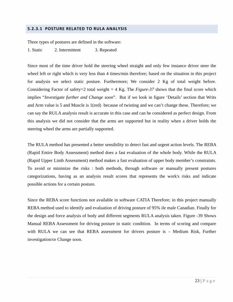
5.2.3.1 POSTURE RELATED TO RULA ANALYSIS
Three types of postures are defined in the software:
1. Static 2. Intermittent 3. Repeated
Since most of the time driver hold the steering wheel straight and only few instance driver steer the
wheel left or right which is very less than 4 times/min therefore; based on the situation in this project
for analysis we select static posture. Furthermore; We consider 2 Kg of total weight before.
Considering Factor of safety=2 total weight = 4 Kg. The Figure-37 shows that the final score which
implies “Investigate further and Change soon”. But if we look in figure ‘Details’ section that Writs
and Arm value is 5 and Muscle is 1(red) because of twisting and we can’t change these. Therefore; we
can say the RULA analysis result is accurate in this case and can be considered as perfect design. From
this analysis we did not consider that the arms are supported but in reality when a driver holds the
steering wheel the arms are partially supported.
The RULA method has presented a better sensibility to detect fast and urgent action levels. The REBA
(Rapid Entire Body Assessment) method does a fast evaluation of the whole body. While the RULA
(Rapid Upper Limb Assessment) method makes a fast evaluation of upper body member’s constraints.
To avoid or minimize the risks : both methods, through software or manually present postures
categorizations, having as an analysis result scores that represents the work's risks and indicate
possible actions for a certain posture.
Since the REBA score functions not available in software CATIA Therefore; in this project manually
REBA method used to identify and evaluation of driving posture of 95% ile male Canadian. Finally for
the design and force analysis of body and different segments RULA analysis taken. Figure -39 Shows
Manual REBA Assessment for driving posture in static condition. In terms of scoring and compare
with RULA we can see that REBA assessment for drivers posture is – Medium Risk, Further
investigation/or Change soon.

24 | P a g e
6.0 REBA ANALYSIS
4 1
1
1
2
2
4
2
7
2
5
Driving Passenger Car 22 11 2009 Maruf Khondker
Figure : 38

25 | P a g e
7.0 BIOMECHANICS SINGLE ACTION ANALYSIS
Biomechanics Single Action Analysis used in this project to evaluate the design. The CATIA
ergonomic tool measures biomechanical data on a worker for a certain posture. The single action
analysis functions calculate lumbar spinal loads (abdominal pressure, abdominal force, and body
movements) and forces and moments on different body segment joints etc those are responsible for
different injury of driver. The forces acting on the manikin's hands and body weight taken into account
in the biomechanical analysis; these forces represent the load of carry, push, lift/ lower, or pull,
depending on the scenario.
To perform this operation click
In the Ergonomics Tools
toolbar, select the Biomechanics:
Single Action Analysis function
then in the specification tree
select a manikin for the analysis.
The Biomechanics Single Action
Analysis dialog box (Figure-39).
Each Tab consist details analysis
result. We can capture the result
of each Tab but because of
software limitation (Scroll bar)
multiple captures needed in each
tab. Therefore; Smart way is,
Export the data to a text file and
reorganize the result according to
the requirement. One of the
snapshots given in figure – 40.
Figure : 39
Figure : 40

26 | P a g e
7.1 BIOMECHANICS ANALYSIS RESULT
Table – 1 Result of SUMMARY DATA TAB ANALYSIS VALUE GROUND REACTION [N]
L4-L5 Moment 19 [Nxm] Total (X) 8 L4-L5 Compression 1081 [N] Total (Y) 0
Body Load Compression 442 [N] Total (Z) 821 Axial Twist Compression 30 [N] Left Foot (X) -25
Flex/Ext Compression 318 [N] Left Foot (Y) 0 L4-L5 Joint Shear 60 Posterior Left Foot (Z) -2471
Abdominal Force [N] 1 [N] Right Foot (X) 33 Abdominal Pressure 0 [N_m2] Right Foot (Y), (Z) 0, 3392
Table – 2 Result of JOINT MOMENT STRENGTH DATA TAB
JOINT DOF MOMENT [Nxm] % POP.NOT CAPABLE
MEAN [Nxm]
S.D [Nxm]
Right Wrist Flexion-Extension 1 Extention 0.1 8 2 Radial-Ulnar Deviation 0 0.0 18 5
Left Wrist Flexion-Extension 0 0.1 8 2 Radial-Ulnar Deviation 1 Ulnar Deviation 0.0 18 5
Right Elbow Flexion-Extension -4 Flexion 0.0 71 15 Supination-pronation 0 0.0 9 2
Left Elbow Flexion-Extension -4 Flexion 0.0 71 15 Supination-pronation 0 0.0 9 2
Right Shoulder Flexion-Extension -11 Flexion 0.0 69 14
Internal-external rotation 4 Abduction DNA DNA DNA 1 Ext. Rotation 0.2 27 9
Left Shoulder Flexion-Extension -12 Flexion 0.0 69 14
Internal-external rotation 1 Abduction DNA DNA DNA 2 Ext. Rotation 0.2 27 9
Lumbar (L4-L5) Flexion-Extension 19 Extension 0.0 369 69
Right-left lateral bend -15 Left Lateral Bend 0.0 148 40 -4 Left Twist 0.0 72 20
Table – 3 Result of SEGMENT POSITIONS TAB
Segments Proximal Coordinates [mm]
Distal Coordinates [mm]
XZ Plane Angle (deg)
YZ Plane Angle (deg)
Center of Gravity Coordinates [mm]
Length

27 | P a g e
Table – 4 Result of REACTION FORCES AND MOMENTS
JOINT Axis Proximal Force [N]
Distal Force [N]
Proximal Moment [Nxm]
Distal Moment [Nxm]
Right Foot X -33 0 143 0 Y 0 0 -353 0 Z -3281 0 -1 0
Right Leg X -33 33 -6 -143 Y 0 0 -1495 353 Z -3243 3281 0 1
Right Thigh X -33 33 44 6 Y 0 0 -2899 1495 Z -3163 3243 0 0
Left Foot X 25 0 79 0 Y 0 0 279 0 Z 2482 0 -1 0
Left Leg X 25 -25 118 -79 Y 0 0 1159 -279 Z 2520 -2482 -1 1
Left Thigh X 25 -25 176 -118 Y 0 0 2276 -1159 Z 2600 -2520 -2 1
Right Hand X 4 0 0 0 Y 0 0 1 0 Z 14 0 0 0
Right Forearm
X 4 -4 0 0 Y 0 0 4 -1 Z 27 -14 0 0
Right Arm X 4 -4 -2 0 Y 0 0 11 -4 Z 49 -27 0 0
Left Hand X 4 0 0 0 Y 0 0 1 0 Z 14 0 0 0
Left Forearm X 4 -4 -1 0 Y 0 0 4 -1 Z 27 -14 0 0
Left Arm X 4 -4 3 1 Y 0 0 11 -4 Z 49 -27 0 0
Head-Neck X 0 0 -1 0 Y 0 0 1 0 Z 65 0 0 0
Pelvis X 8 -8 -25 15 Y 0 0 21 -19 Z 562 -448 0 0
Trunk X 8 -8 -15 -2 Y 0 0 19 -27 Z 448 -163 0 0

28 | P a g e
8. COMAPRING ERGONOMIC AND NON ERGONOMIC BACK SEAT EFFECT ON TRUNK
Figure – 41 shows an ergonomic design back seat
which has perfect posture of 95% male Canadian
Mankin. Figure – 42 Shows a flat non ergonomic
back seat. Comparing Both figures biomechanics
single action analysis result we found that :
• L4-L5 Moment of Ergonomic Design is ~
40% less than Non Ergonomic Design.
• L4-L5 Compression of Ergonomic Design is
~ 30% less than Non Ergonomic Design.
• Axial Twist Compression of Ergonomic
Design is ~ 30% less than Non Ergonomic
Design.
• Flexural Compression of Ergonomic Design
is ~ 40% less than Non Ergonomic Design.
The above comparison shows ergonomic design back seat can reduce L4-L5 moment and compression
significantly than non ergonomic design. But here we consider only the back seat. If we consider an
ergonomic design of Seat Base (Page – 10 Section 4.4 – Figure -11) then the compression and moment
can reduce more. However; this design is based for 95% male but other short driver 5% female may not
have exact posture as 95% Male because of height. Therefore Seat back need to adjust to get a good
lumber support which is discussed next section (recommendation).
Figure : 41 Figure : 42

29 | P a g e
9. SOME RECOMMENDATIONS OF CORRECT SITTING, SEAT DESIGN AND THE DRIVERS
DESIGN :
Back seat design was
perfect for 95% Male for
perfect lumber support. But
for 5% shorter Female
figure-43 Red mark area:
thoracic level no support.
That case driver has only
choice to adjust the head set.
If we can arrange the seat in
such a way so that Driver
can adjust the back seat Up-
Down figure-44 than we can
provide full lumber support.
As a result it can be access
by wide range of people.
DRIVER HABIT:
• Driver should have a good rest in the interval of driving to regain muscle strength.
• Driver should maintain neutral posture and incline the back seat as requirement so that muscle
should not feel stress all the time.
• When the pedals are fully pressed Driver should adjust spine back until to get contact with the
back of the seat.
• Drivers should adjust the seat in such way that knees are as less bent as possible.
• Driver should adjust the height of seat from floor so that he/she line of sight of eyes over the
steering wheel and have a perfect vision.
Figure : 43 Figure : 44

30 | P a g e
SEAT FEATURES:
• All range of Driver should be able to adjust all features of seat with minimum bend and
twisting. Seating adjustable features should be simple in design and handy for driver.
• Head set length and width should be enough to support wide range of people and it can be
adjustable in two directions: Up and Down, Bending in the direction of drivers seating.
• Seat base material should not hard and should not very soft because hard material give
discomfort in thigh and hip and soft material resist muscle to supply enough blood.
• Select good seat base material so that it can not contain any moisture.
• Ensure that the side bolster of the seat should be close enough so that the body supported
comfortably without any pressure at any side.
• Ensure that seat base is not too short and not too long.
• Ensure that seat base little wider than hips and thigh and consider 95% ile male dimension.
• Seating adjustable feature should not exceed angular limitation of human body parts.
• Seat cushion and seat cover if used should be tight enough with seat base and seat back so that
it won’t affect drivers posture while driving.

31 | P a g e
10. DISCUSSION
To design a passenger car vehicle seat : In terms of ergonomics and as an engineer we must have to
implement human factors and the seat should capable to fit for wide ranges of people with providing
comfort and safety. To meet the requirement of wide range of people proper adjustment of car seat
recommended. Considering the limitation of car space, in this project most important human posture
was analyzed to get a correct sitting and seat. To achieve this three types of analysis-RULA Analysis,
Biomechanics Single Action Analysis and Open Vision Analysis performed. At the end we found that
correct posture and ergonomic seat can reduced the moment and compression of driver significantly. As
a result the driver short term and long term injury can be reduced. Not only reducing injury but also
ergonomic design seat can relax the muscles in the back and also can reduce the stress in the spinal
column which has direct impact on drivers comfort. Furthermore; considering correct sitting
recommendation (Chapter –7) the drivers can reduce the risk of the ergonomic problems.

32 | P a g e
11. CONCLUSION
During working throughout the project I got in-depth understanding and knowledge of different type
Ergonomics problem and their possible solution. This Project “Ergonomic Car Seat design and
Analysis” is one in of them. But after this project I am confident to execute any kind of ergonomics
related project. Apart from this, I tried my best to implement my ideas and knowledge what I learnt so
far into academic premises and also in real case. At the same time I also got a feeling of the challenges
behind the design and workspace requirement, limitation. Furthermore throughout the project I learned
a lot how to implement and solve ergonomic problem using professional software (CATIA).
Undoubtedly, this project has enhanced my capability to learn and implement it step by step to achieve
a target within a stipulated time line. Certainly this project would increase my level of confidence and
cast ample ray of light to the practical working world outside of the academic premises.

33 | P a g e
12. REFERENCES
(1) Instructor Class Note and supplied Material: INDU 6411 Fall 2009 Concordia University.
(2) CATIA V5 Help File.
(3) Julian Happen-Smith – “An Introduction to Modern Vehicle Design Chapter 9 “
(4) R.S. Bridger “Introduction to Ergonomics, Third Edition”
(5) Karl Kroemer et al.Prentice Hall, “How to Design for Ergonomics and Efficiency”
(6) H-Point and D-Point in the Pelvis “The Initial Position and Postural Attitude of Vehicle
Operators. Raymond R. Brodeur, Yuntao Cui, Herbert M. Reynolds August 15, 1995
(7) Automobile seat comfort: occupant preferences vs. anthropometric accommodation the Modern
Motor Car.”Department of Industrial & Manufacturing Systems Engineering, University of
Windsor, Ont., Canada