Embed Size (px)
Citation preview
Marlon Xplore II / Xplore Pro II
Installation & Assembly
Instructions
Marlon Recreational Products
www.marlonproducts.com
1-800-663-7367
INSTALLATION INSTRUCTIONS: 1. Remove the ramp from underneath the deck to lighten the deck’s weight.
2. With the assistance of 2-3 others, lift the deck into the back of the truck (approx weight is
375lbs without the ramp)
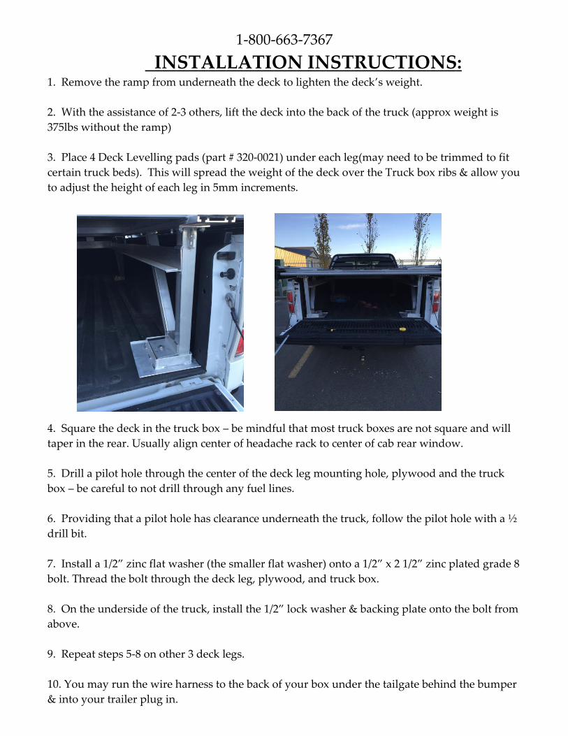
3. Place 4 Deck Levelling pads (part # 320-0021) under each leg(may need to be trimmed to fit
certain truck beds). This will spread the weight of the deck over the Truck box ribs & allow you
to adjust the height of each leg in 5mm increments.
4. Square the deck in the truck box – be mindful that most truck boxes are not square and will
taper in the rear. Usually align center of headache rack to center of cab rear window.
5. Drill a pilot hole through the center of the deck leg mounting hole, plywood and the truck
box – be careful to not drill through any fuel lines.
6. Providing that a pilot hole has clearance underneath the truck, follow the pilot hole with a ½
drill bit.
7. Install a 1/2” zinc flat washer (the smaller flat washer) onto a 1/2” x 2 1/2” zinc plated grade 8
bolt. Thread the bolt through the deck leg, plywood, and truck box.
8. On the underside of the truck, install the 1/2” lock washer & backing plate onto the bolt from
above.
9. Repeat steps 5-8 on other 3 deck legs.
10. You may run the wire harness to the back of your box under the tailgate behind the bumper
& into your trailer plug in.
Note: For Permanent Light Hook Up
10a. Remove the left rear light assembly from your truck.
10b. Cut the trailer plug off of the wire harness & thread the bare ends through the access hole
in the truck box.
10c. Ascertain which light is the tail-light & which is the break light (turn marker lights on, tail-
light bulb will light up).
10d. The deck lights are as follows white is ground, brown is your running lights and green is
the rear brake light.
10e. Using quick connectors or solder, tap into tail lights, wiring, paying attention to (+) & (-)
polarity.
10f. Use electrical tape or shrink on connections and replace the rear light assembly.
11. Under deck & Headache Rack light switch is located at the rear on the inside of the back
tube frame on the right.
Note: The white wire on the LED light bar needs to be connected to the reverse light wire. We
recommend having a certified auto electrical tech, solder it to the wire behind the left rear
taillight.
STORAGE OF THE RAMP During transport and storage, your snowmobile/ATV ramp will store in a pocket underneath
the surface of your Marlon Truck Deck. This preserves most of the cargo carrying capability of
your truck box.
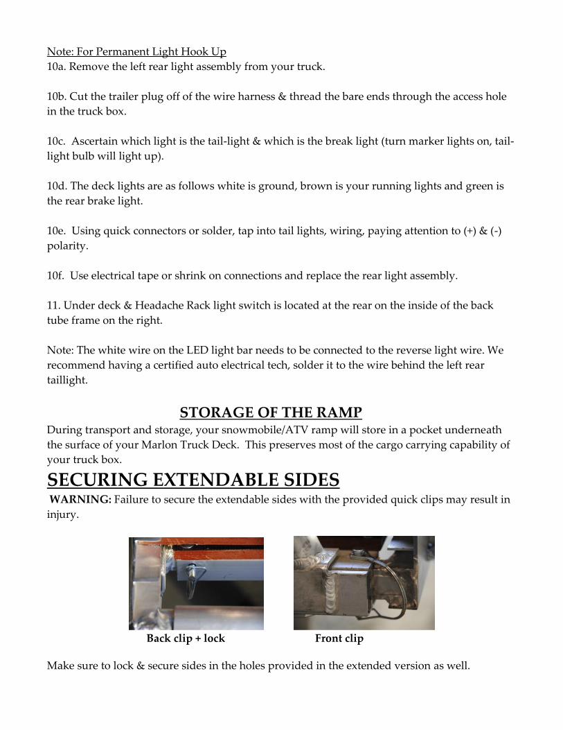
SECURING EXTENDABLE SIDES WARNING: Failure to secure the extendable sides with the provided quick clips may result in
injury.
Back clip + lock Front clip
Make sure to lock & secure sides in the holes provided in the extended version as well.
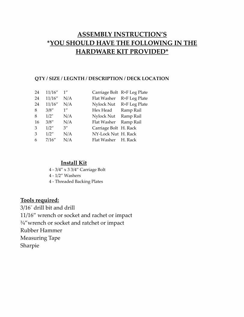
ASSEMBLY INSTRUCTION’S
*YOU SHOULD HAVE THE FOLLOWING IN THE
HARDWARE KIT PROVIDED*
QTY / SIZE / LEGNTH / DESCRIPTION / DECK LOCATION
24 11/16” 1” Carriage Bolt R+F Leg Plate
24 11/16” N/A Flat Washer R+F Leg Plate
24 11/16” N/A Nylock Nut R+F Leg Plate
8 3/8” 1” Hex Head Ramp Rail
8 1/2" N/A Nylock Nut Ramp Rail
16 3/8” N/A Flat Washer Ramp Rail
3 1/2” 3” Carriage Bolt H. Rack
3 1/2” N/A NY-Lock Nut H. Rack
6 7/16” N/A Flat Washer H. Rack
Install Kit 4 - 3/4” x 3 3/4” Carriage Bolt
4 - 1/2” Washers
4 - Threaded Backing Plates
Tools required:
3/16” drill bit and drill
11/16” wrench or socket and rachet or impact
¾”wrench or socket and ratchet or impact
Rubber Hammer
Measuring Tape
Sharpie
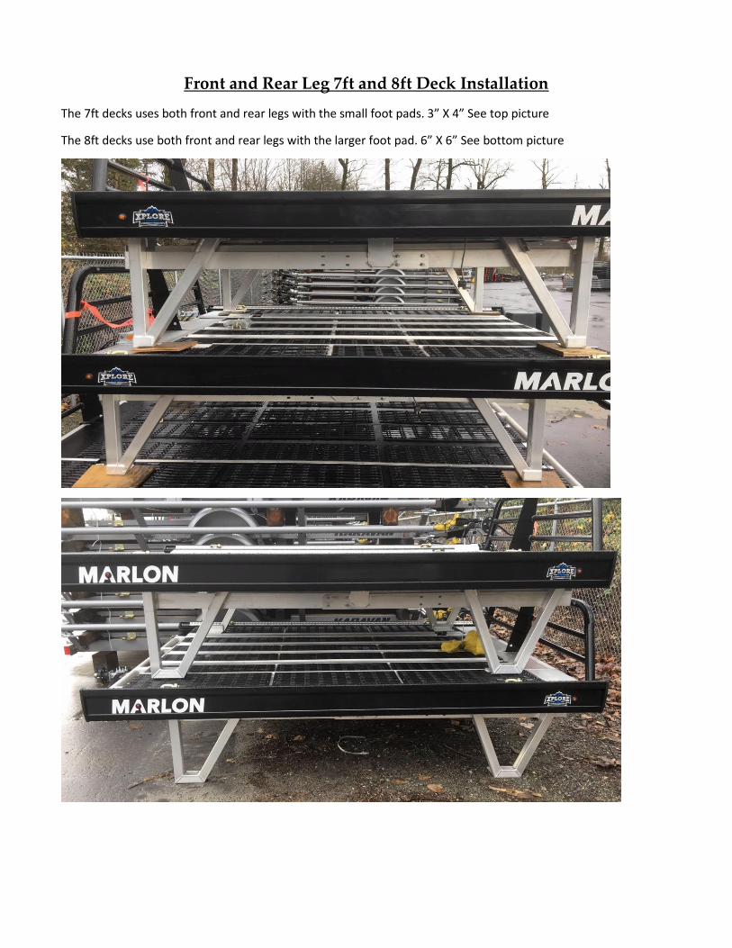
Front and Rear Leg 7ft and 8ft Deck Installation
The 7ft decks uses both front and rear legs with the small foot pads. 3” X 4” See top picture
The 8ft decks use both front and rear legs with the larger foot pad. 6” X 6” See bottom picture
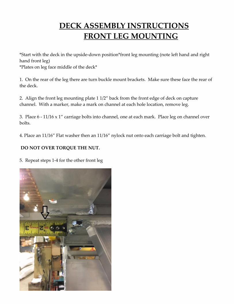
DECK ASSEMBLY INSTRUCTIONS
FRONT LEG MOUNTING
*Start with the deck in the upside-down position*front leg mounting (note left hand and right
hand front leg)
*Plates on leg face middle of the deck*
1. On the rear of the leg there are turn buckle mount brackets. Make sure these face the rear of
the deck.
2. Align the front leg mounting plate 1 1/2” back from the front edge of deck on capture
channel. With a marker, make a mark on channel at each hole location, remove leg.
3. Place 6 - 11/16 x 1” carriage bolts into channel, one at each mark. Place leg on channel over
bolts.
4. Place an 11/16” Flat washer then an 11/16” nylock nut onto each carriage bolt and tighten.
DO NOT OVER TORQUE THE NUT.
5. Repeat steps 1-4 for the other front leg
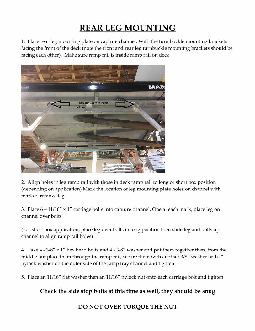
REAR LEG MOUNTING
1. Place rear leg mounting plate on capture channel. With the turn buckle mounting brackets
facing the front of the deck (note the front and rear leg turnbuckle mounting brackets should be
facing each other). Make sure ramp rail is inside ramp rail on deck.
2. Align holes in leg ramp rail with those in deck ramp rail to long or short box position
(depending on application) Mark the location of leg mounting plate holes on channel with
marker, remove leg.
3. Place 6 – 11/16” x 1” carriage bolts into capture channel. One at each mark, place leg on
channel over bolts
(For short box application, place leg over bolts in long position then slide leg and bolts up
channel to align ramp rail holes)
4. Take 4 - 3/8” x 1” hex head bolts and 4 - 3/8” washer and put them together then, from the
middle out place them through the ramp rail, secure them with another 3/8” washer or 1/2”
nylock washer on the outer side of the ramp tray channel and tighten.
5. Place an 11/16” flat washer then an 11/16” nylock nut onto each carriage bolt and tighten
Check the side stop bolts at this time as well, they should be snug
DO NOT OVER TORQUE THE NUT
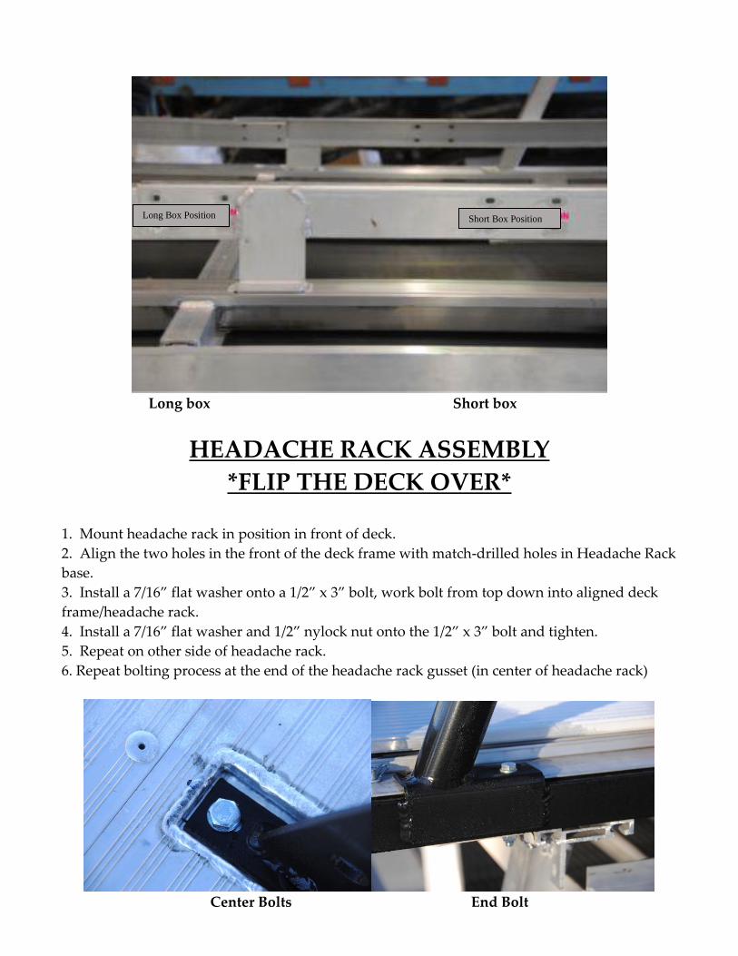
Long box Short box
HEADACHE RACK ASSEMBLY
*FLIP THE DECK OVER* 1. Mount headache rack in position in front of deck.
2. Align the two holes in the front of the deck frame with match-drilled holes in Headache Rack
base.
3. Install a 7/16” flat washer onto a 1/2” x 3” bolt, work bolt from top down into aligned deck
frame/headache rack.
4. Install a 7/16” flat washer and 1/2” nylock nut onto the 1/2” x 3” bolt and tighten.
5. Repeat on other side of headache rack.
6. Repeat bolting process at the end of the headache rack gusset (in center of headache rack)
Center Bolts End Bolt
Long Box Position Short Box Position
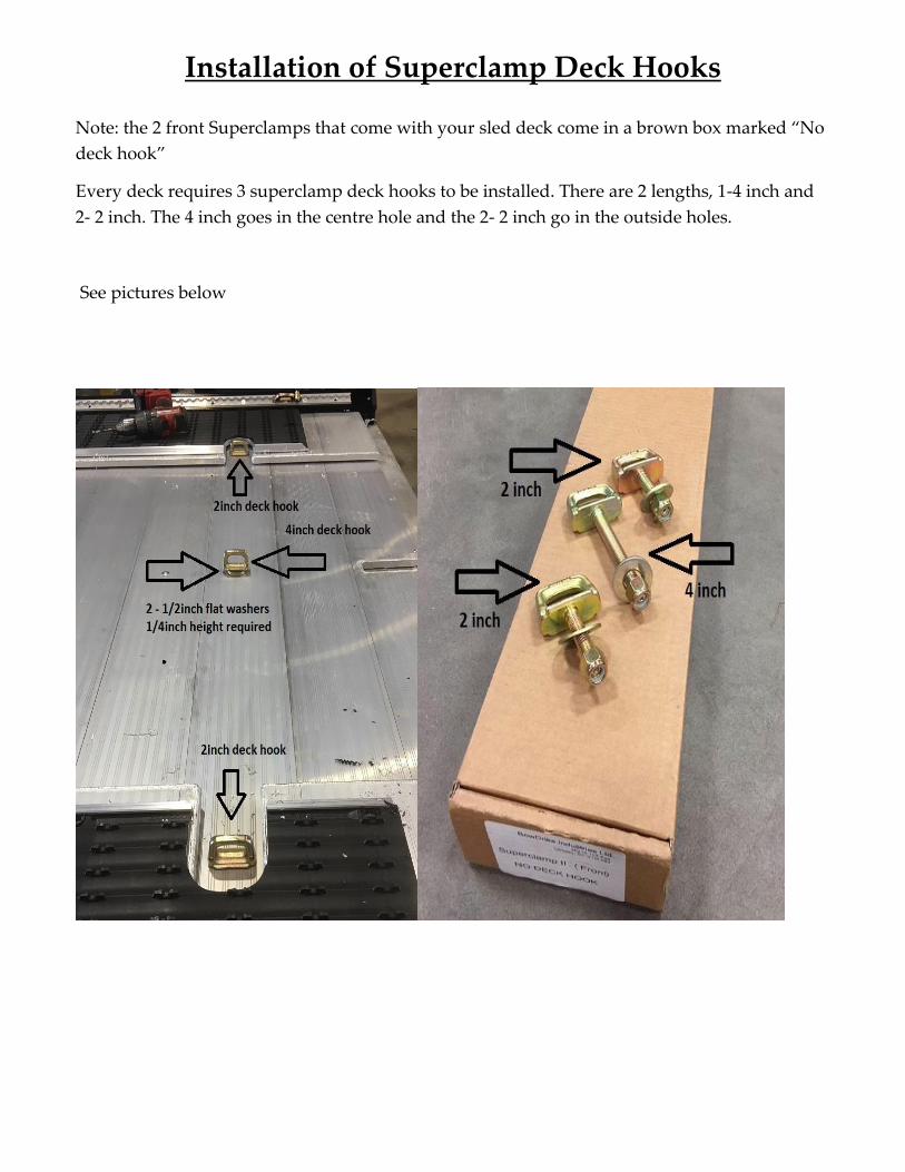
Installation of Superclamp Deck Hooks
Note: the 2 front Superclamps that come with your sled deck come in a brown box marked “No
deck hook”
Every deck requires 3 superclamp deck hooks to be installed. There are 2 lengths, 1-4 inch and
2- 2 inch. The 4 inch goes in the centre hole and the 2- 2 inch go in the outside holes.
See pictures below
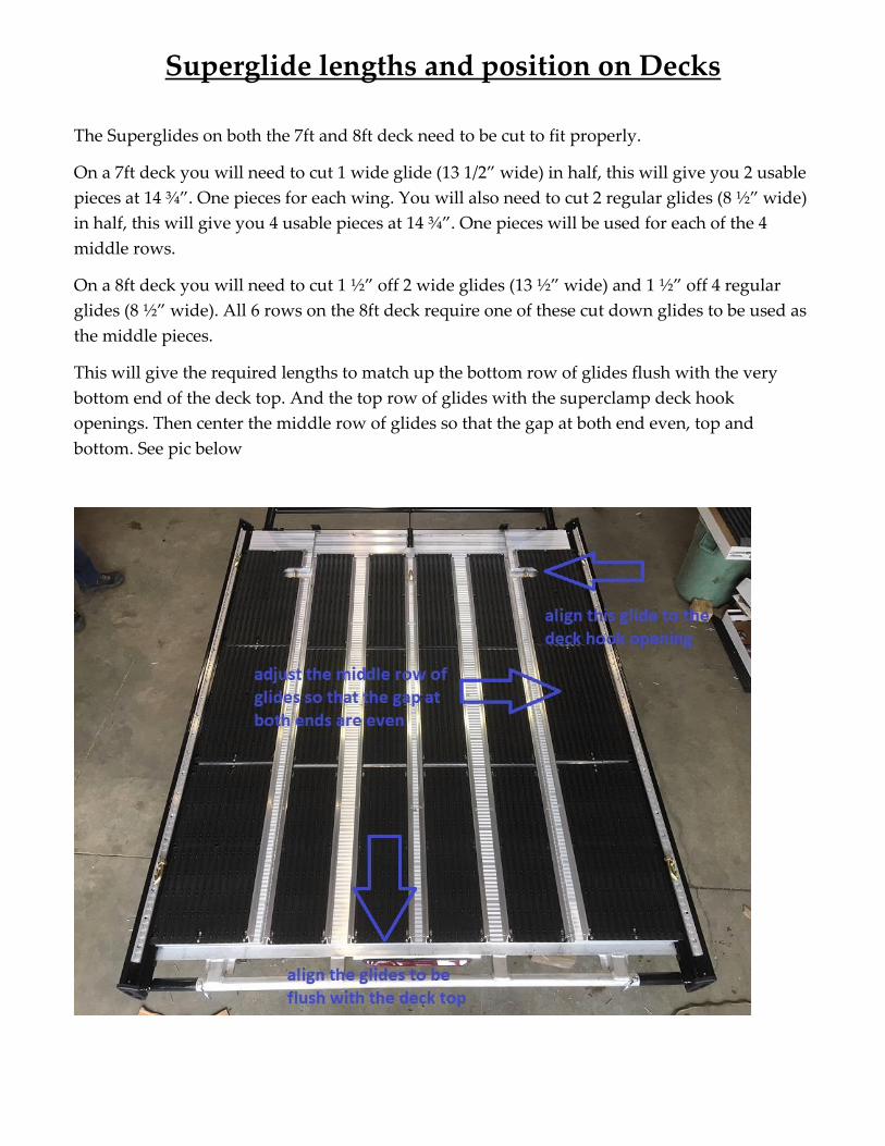
Superglide lengths and position on Decks
The Superglides on both the 7ft and 8ft deck need to be cut to fit properly.
On a 7ft deck you will need to cut 1 wide glide (13 1/2” wide) in half, this will give you 2 usable
pieces at 14 ¾”. One pieces for each wing. You will also need to cut 2 regular glides (8 ½” wide)
in half, this will give you 4 usable pieces at 14 ¾”. One pieces will be used for each of the 4
middle rows.
On a 8ft deck you will need to cut 1 ½” off 2 wide glides (13 ½” wide) and 1 ½” off 4 regular
glides (8 ½” wide). All 6 rows on the 8ft deck require one of these cut down glides to be used as
the middle pieces.
This will give the required lengths to match up the bottom row of glides flush with the very
bottom end of the deck top. And the top row of glides with the superclamp deck hook
openings. Then center the middle row of glides so that the gap at both end even, top and
bottom. See pic below
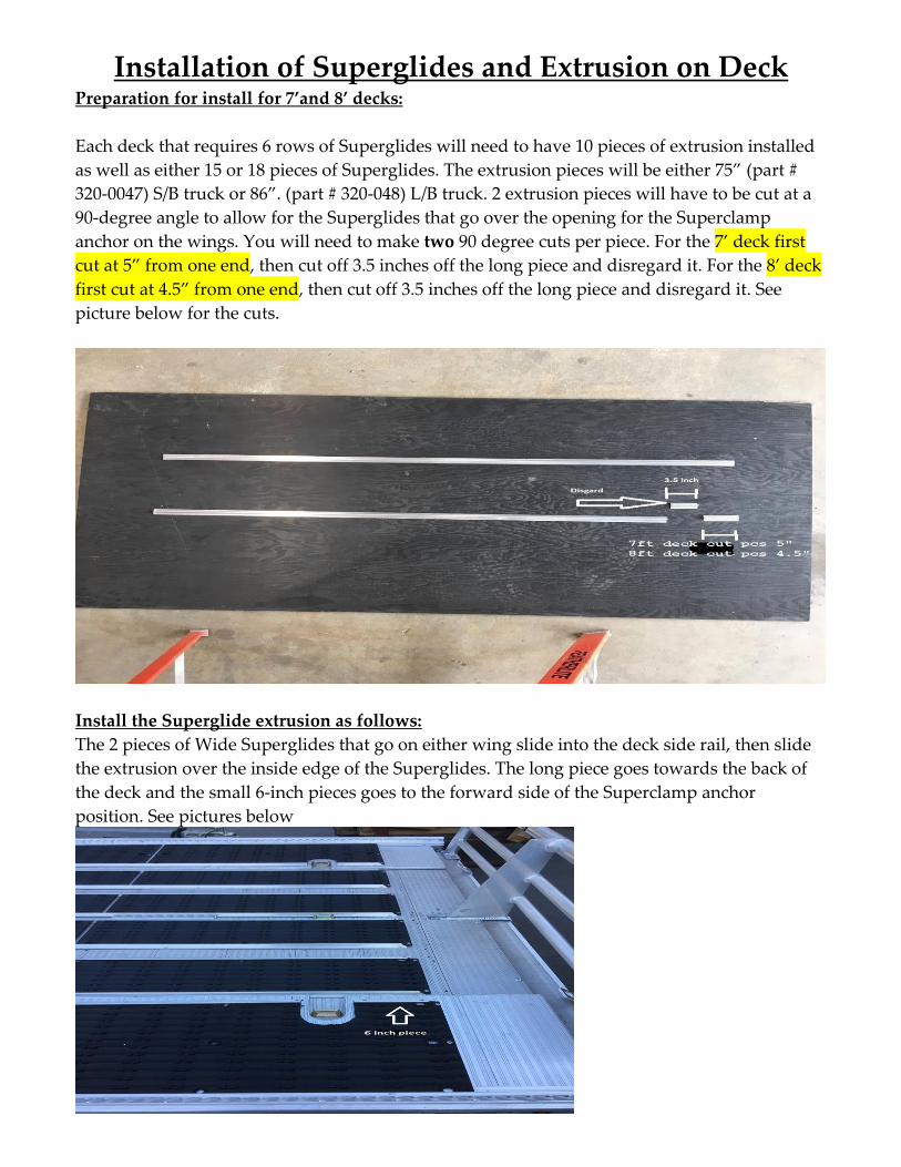
Installation of Superglides and Extrusion on Deck Preparation for install for 7’and 8’ decks:
Each deck that requires 6 rows of Superglides will need to have 10 pieces of extrusion installed
as well as either 15 or 18 pieces of Superglides. The extrusion pieces will be either 75” (part #
320-0047) S/B truck or 86”. (part # 320-048) L/B truck. 2 extrusion pieces will have to be cut at a
90-degree angle to allow for the Superglides that go over the opening for the Superclamp
anchor on the wings. You will need to make two 90 degree cuts per piece. For the 7’ deck first
cut at 5” from one end, then cut off 3.5 inches off the long piece and disregard it. For the 8’ deck
first cut at 4.5” from one end, then cut off 3.5 inches off the long piece and disregard it. See
picture below for the cuts.
Install the Superglide extrusion as follows:
The 2 pieces of Wide Superglides that go on either wing slide into the deck side rail, then slide
the extrusion over the inside edge of the Superglides. The long piece goes towards the back of
the deck and the small 6-inch pieces goes to the forward side of the Superclamp anchor
position. See pictures below
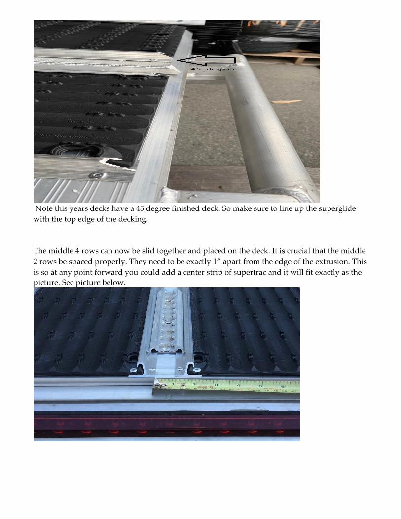
Note this years decks have a 45 degree finished deck. So make sure to line up the superglide
with the top edge of the decking.
The middle 4 rows can now be slid together and placed on the deck. It is crucial that the middle
2 rows be spaced properly. They need to be exactly 1” apart from the edge of the extrusion. This
is so at any point forward you could add a center strip of supertrac and it will fit exactly as the
picture. See picture below.
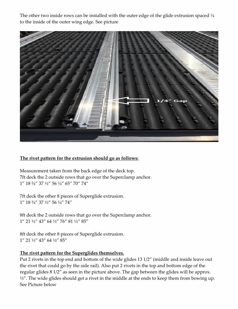
The other two inside rows can be installed with the outer edge of the glide extrusion spaced ¼
to the inside of the outer wing edge. See picture
The rivet pattern for the extrusion should go as follows:
Measurement taken from the back edge of the deck top.
7ft deck the 2 outside rows that go over the Superclamp anchor.
1” 18 ¾” 37 ½” 56 ¼” 65” 70” 74”
7ft deck the other 8 pieces of Superglide extrusion.
1” 18 ¾” 37 ½” 56 ¼” 74”
8ft deck the 2 outside rows that go over the Superclamp anchor.
1” 21 ½” 43” 64 ½” 76” 81 ½” 85”
8ft deck the other 8 pieces of Superglide extrusion.
1” 21 ½” 43” 64 ½” 85”
The rivet pattern for the Superglides themselves.
Put 2 rivets in the top end and bottom of the wide glides 13 1/2” (middle and inside leave out
the rivet that could go by the side rail). Also put 2 rivets in the top and bottom edge of the
regular glides 8 1/2” as seen in the picture above. The gap between the glides will be approx.
½”. The wide glides should get a rivet in the middle at the ends to keep them from bowing up.
See Picture below
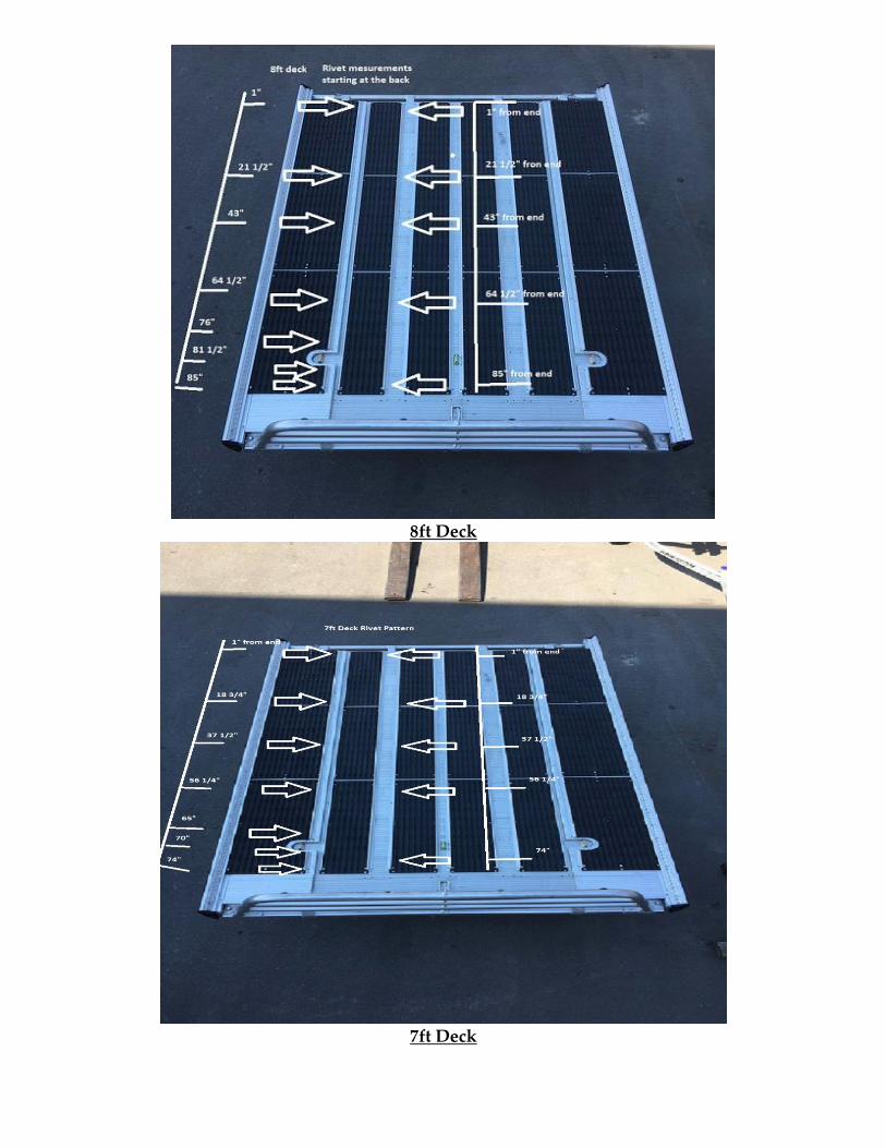
8ft Deck
7ft Deck
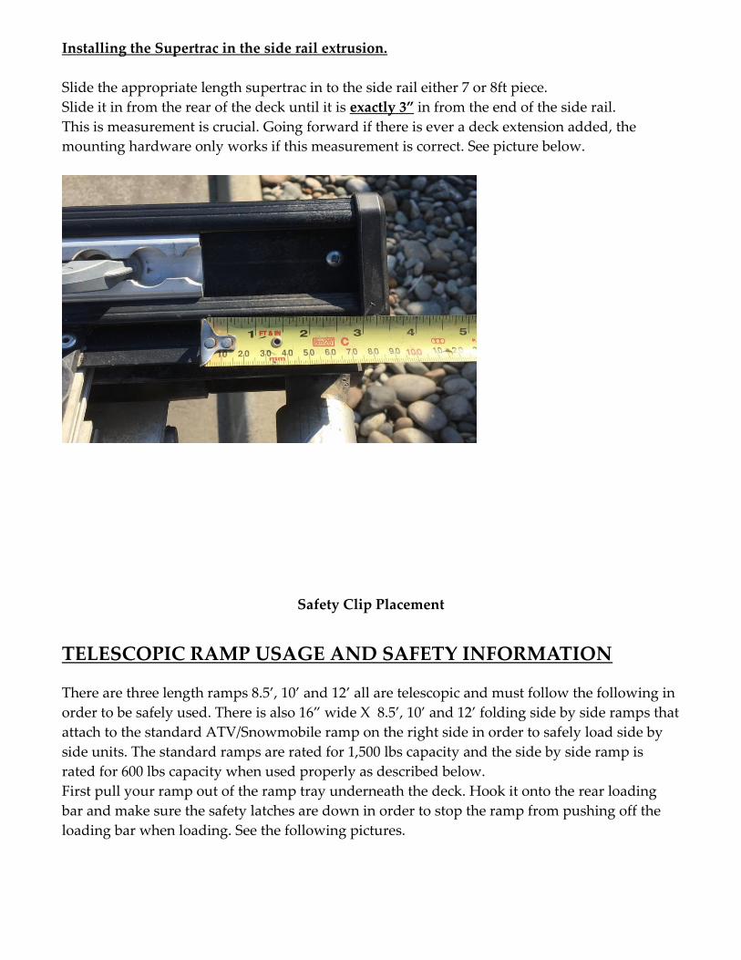
Installing the Supertrac in the side rail extrusion.
Slide the appropriate length supertrac in to the side rail either 7 or 8ft piece.
Slide it in from the rear of the deck until it is exactly 3” in from the end of the side rail.
This is measurement is crucial. Going forward if there is ever a deck extension added, the
mounting hardware only works if this measurement is correct. See picture below.
Safety Clip Placement
TELESCOPIC RAMP USAGE AND SAFETY INFORMATION
There are three length ramps 8.5’, 10’ and 12’ all are telescopic and must follow the following in
order to be safely used. There is also 16” wide X 8.5’, 10’ and 12’ folding side by side ramps that
attach to the standard ATV/Snowmobile ramp on the right side in order to safely load side by
side units. The standard ramps are rated for 1,500 lbs capacity and the side by side ramp is
rated for 600 lbs capacity when used properly as described below.
First pull your ramp out of the ramp tray underneath the deck. Hook it onto the rear loading
bar and make sure the safety latches are down in order to stop the ramp from pushing off the
loading bar when loading. See the following pictures.
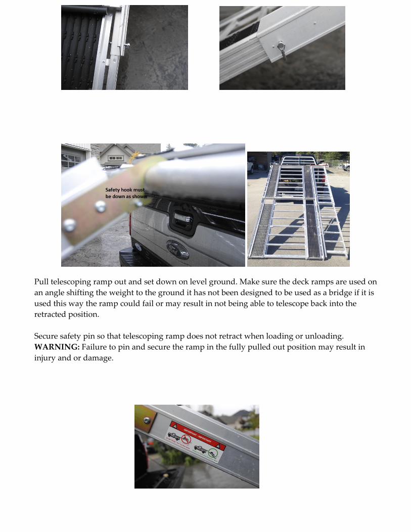
Pull telescoping ramp out and set down on level ground. Make sure the deck ramps are used on
an angle shifting the weight to the ground it has not been designed to be used as a bridge if it is
used this way the ramp could fail or may result in not being able to telescope back into the
retracted position.
Secure safety pin so that telescoping ramp does not retract when loading or unloading.
WARNING: Failure to pin and secure the ramp in the fully pulled out position may result in
injury and or damage.
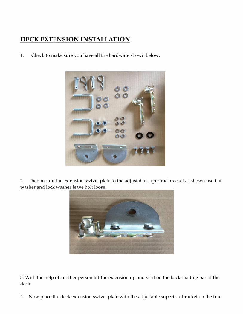
DECK EXTENSION INSTALLATION
1. Check to make sure you have all the hardware shown below.
2. Then mount the extension swivel plate to the adjustable supertrac bracket as shown use flat
washer and lock washer leave bolt loose.
3. With the help of another person lift the extension up and sit it on the back-loading bar of the
deck.
4. Now place the deck extension swivel plate with the adjustable supertrac bracket on the trac
so that the hole on the swivel plate is slightly ahead of the hole in the extension arm. Push the
supertrac bracket into the trac and pull back to lock it in place.
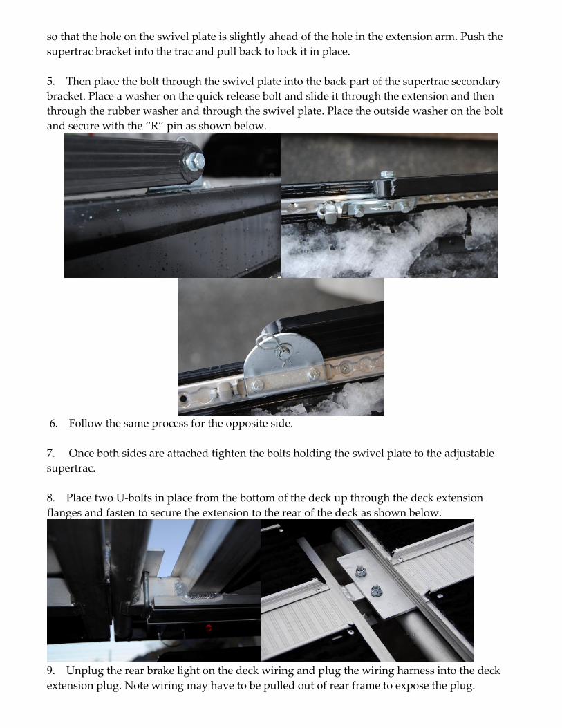
5. Then place the bolt through the swivel plate into the back part of the supertrac secondary
bracket. Place a washer on the quick release bolt and slide it through the extension and then
through the rubber washer and through the swivel plate. Place the outside washer on the bolt
and secure with the “R” pin as shown below.
6. Follow the same process for the opposite side.
7. Once both sides are attached tighten the bolts holding the swivel plate to the adjustable
supertrac.
8. Place two U-bolts in place from the bottom of the deck up through the deck extension
flanges and fasten to secure the extension to the rear of the deck as shown below.
9. Unplug the rear brake light on the deck wiring and plug the wiring harness into the deck
extension plug. Note wiring may have to be pulled out of rear frame to expose the plug.
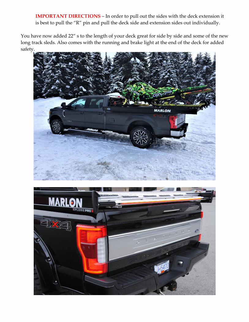
IMPORTANT DIRECTIONS – In order to pull out the sides with the deck extension it
is best to pull the “R” pin and pull the deck side and extension sides out individually.
You have now added 22” s to the length of your deck great for side by side and some of the new
long track sleds. Also comes with the running and brake light at the end of the deck for added
safety.
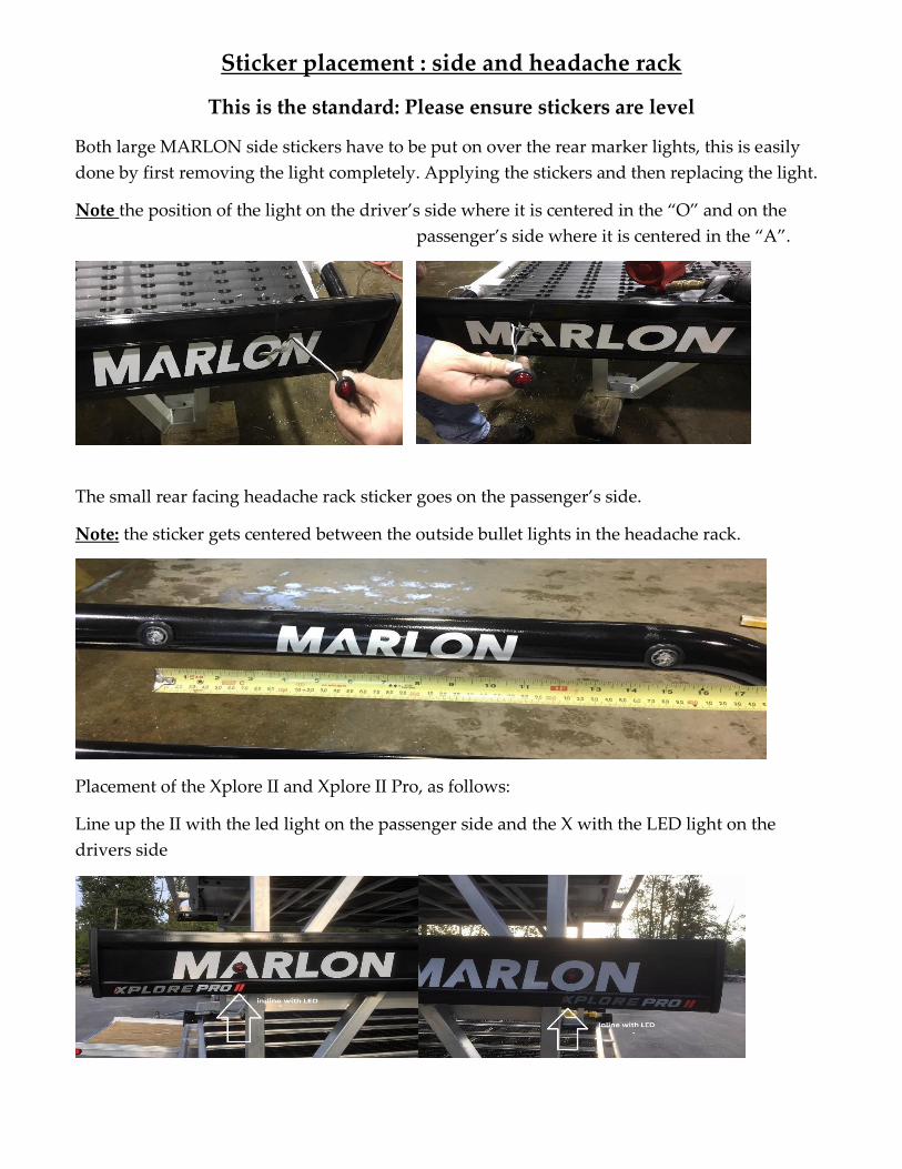
Sticker placement : side and headache rack
This is the standard: Please ensure stickers are level
Both large MARLON side stickers have to be put on over the rear marker lights, this is easily
done by first removing the light completely. Applying the stickers and then replacing the light.
Note the position of the light on the driver’s side where it is centered in the “O” and on the
passenger’s side where it is centered in the “A”.
The small rear facing headache rack sticker goes on the passenger’s side.
Note: the sticker gets centered between the outside bullet lights in the headache rack.
Placement of the Xplore II and Xplore II Pro, as follows:
Line up the II with the led light on the passenger side and the X with the LED light on the
drivers side
ADDITIONAL IMPORTANT SAFETY INFORMATION
Deck must be securely anchored to the vehicle by one bolt through EACH deck leg and the
truck box bed. Inspect your deck monthly for loose connection.
Deck is approximately 450 lbs including ramp.
Deck, load and vehicle must not exceed GVW of vehicle.
Maximum deck load, evenly distributed is 2,000 pounds.
Skewed uneven loads reduce capacity.
Ensure front and rear of load is securely attached to deck prior to vehicle start-up.
Loading Ramp(s) are not designed to be used as a bridge and cannot sustain the loading
weight if used this way.
Make sure safety pin in secured in place to stop the telescopic ramp from moving inward
before loading or unloading.
Before traveling with the Deck Extension in the forward unused position make sure it is tied
down with the strap provided.
To purchase replacement parts (install kit, LED lights, Side by Side ramp, Deck leveling kit etc)
Contact your dealer or Marlon Recreational Products directly at 1-800-663-7367.
To view other great Marlon products, visit our website.
www.marlonproducts.com
Marlon Recreational Products Proudly serving you from:
Chilliwack, BC Office 1-800-663-7367
Stony Plain, AB Office 1-855-962-5500
St. Andrews, MB Office 1-855885-9150
Tacoma, WA Office 1-866-930-9411
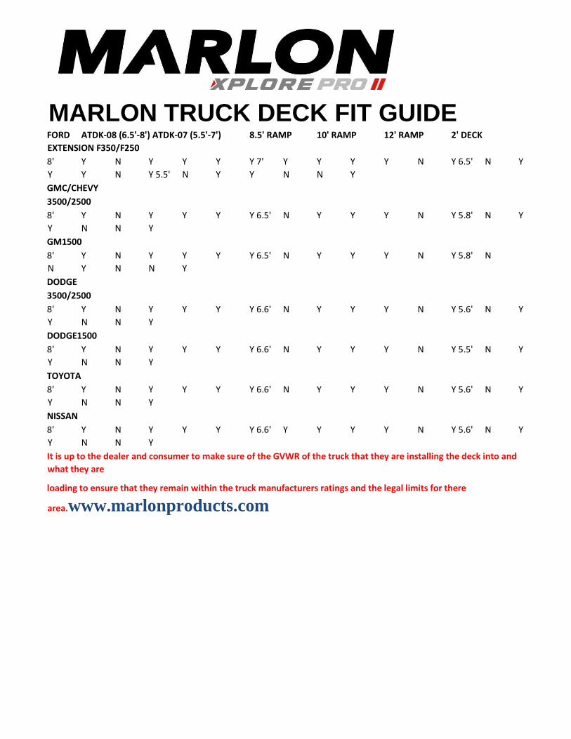
MARLON TRUCK DECK FIT GUIDE
FORD ATDK-08 (6.5'-8') ATDK-07 (5.5'-7') 8.5' RAMP 10' RAMP 12' RAMP 2' DECK
EXTENSION F350/F250
8' Y N Y Y Y Y 7' Y Y Y Y N Y 6.5' N Y
Y Y N Y 5.5' N Y Y N N Y
GMC/CHEVY
3500/2500
8' Y N Y Y Y Y 6.5' N Y Y Y N Y 5.8' N Y
Y N N Y
GM1500
8' Y N Y Y Y Y 6.5' N Y Y Y N Y 5.8' N
N Y N N Y
DODGE
3500/2500
8' Y N Y Y Y Y 6.6' N Y Y Y N Y 5.6' N Y
Y N N Y
DODGE1500
8' Y N Y Y Y Y 6.6' N Y Y Y N Y 5.5' N Y
Y N N Y
TOYOTA
8' Y N Y Y Y Y 6.6' N Y Y Y N Y 5.6' N Y
Y N N Y
NISSAN
8' Y N Y Y Y Y 6.6' Y Y Y Y N Y 5.6' N Y
Y N N Y
It is up to the dealer and consumer to make sure of the GVWR of the truck that they are installing the deck into and
what they are
loading to ensure that they remain within the truck manufacturers ratings and the legal limits for there
area.www.marlonproducts.com