Embed Size (px)
Citation preview

Mark AnstromStructural option MAE/BAE
AE Senior Thesis presentationStrathmore Park at Grosvenor Metro North
Bethesda, MD

Strathmore Park at Grosvenor Metro

Project Overview Located in North Bethesda, MD.
A Washington, D.C. suburb. 3 identical buildings – same
design structurally 4 identical floors of luxury
condominiums over a 1 story parking garage
2 hydraulic elevators 2 stair towers Individual HVAC units per Condo High end finishes, fixtures and
appliances Very spacious 2-3 bedroom units Building has sprinkler system

Strathmore Park at Grosvenor Metro
1 2 3
4 5

Current Construction Completed December, 2002 10” CIP concrete flat slab f’c = 4 ksi Punching shear reinforcement
provided by steel studrails Lateral forces resisted by centrally
located shearwalls

Thesis Proposal
Redesign Strathmore Park using: Wood construction Steel construction
Why? – Many reasons, these were the most viable systems for the layout
Compare and contrast the three systems
What are the advantages and disadvantages?

Considerations Maintain same architectural appearance as
original design (such as ceiling height) Preserve acoustical quality Check trusses for vibration Ensure proper fire ratings Check ponding on flat roof

Presentation preview Wood design summary
Steel design summary
Breadth – fire, acoustics, vibration, cost
Comparison – wood, steel, and concrete
Conclusion

Wood Design
16” Wood trusses with dimension lumber bearing walls

The design

The designfloor system
16” deep single 2x4 top and bottom chord plate-connected floor trusses
Based on deflection, moment of inertia and span
Simple span condition throughout building
Topped with 23/32” T&G structural panels and ¾” cementitious topping (UL # L521)
12” transfer slab at first floor (From ADOSS)

The designbearing wall system
2x4 SPF #2 dimensional lumber
Designed for combined axial and wind load
Double top plate per code Spacing ranges from (1)
stud @ 24” o.c to studs at 12” o.c. doubled under trusses.
TYP. EXTERIOR WALLTRUSSES PERPENDICULAR
2x4 BLOCKING MIDWAY BETWEEN TRUSSES
23/32" PLYWOOD FLOOR SHEATHING
2x4 CONTINUOUS RIBBON
WOOD STUDS SEE SCHEDULE

The designbeams, headers, and columns
Built-up SPF #2 dimensional lumber members. (2)2x6 to (2)2x12
Structural composite lumber members used where required. 1.9E microllam (2)1 ¾” x 9 ½” LVL to (2)1 ¾ x 14” LVL
Columns are built-up 2x4s, worst case (6) studs
FLUSH BEAM SEE PLAN FOR SIZE
BOTTOM CHORD BEARING W/ HANGERS
TYPICAL FLUSH BEAM
16" DEEP PREFABRICATED PLATE CONNECTED FLOOR TRUSSES
SIMPSON TRUSS HANGER
3/4" GYPCRETE TOPPING
23/32" PLYWOOD FLOOR SHEATHING

The designLateral system
Bearing walls sheathed in Structural Panels or Gyp Board for lateral resistance
Wind loads distributed to walls by tributary area
Unit separation walls and corridor walls act as shear walls
Overturning not an issue
15.2 PSF
14.3 PSF
13.2 PSF
11.9 PSF
11.2 PSF
10.4 PSF
9.5 PSF
13.6 PSF UPLIFT
5.0 PSF LEEWARD
WINDWARD

Architectural modifications
Columns can be eliminated
Floor depth increases to ~18”, but…
Dropped ceilings for MEP can be eliminated
Wall thickness changes (unnoticeable)
ORIGINAL CONCRETE DESIGN WOOD DESIGN - COLUMNS ELIMINATED
ORIGINAL CONCRETE DESIGN WOOD DESIGN - COLUMNS ELIMINATED

Advantages Wood is less expensive
~$109/sf vs. ~$165/sf total costs Wood construction is faster The design doesn’t require a great deal of skilled
labor No intrusive concrete or steel columns No ceiling drops – plenum No formwork – No stripping Shorter lead time for trusses than steel

Disadvantages Because these are high end condos, the owner
chose concrete over this option because of the durability of concrete over wood
Direct relationship between architectural form and structural form
Transfer slab required at garage level

Composite steel Design
w-shape Steel beams, girders and columns
The design

The design

The designFloor system
Topping slab – 5” thick 4000 psi concrete slab on 1 ½” B-lok composite metal deck
¾”x 4 ½” shear studs 50 ksi W-Shape beams,
girders and columns Beam and girder Sizes
range from W8 to W16 Column sizes W8 or W10
in some cases
WIDE FLANGE BEAM TOP FLANGE COPEDSEE PLAN FOR SIZE
5" NORMAL WEIGHT CONCRETE TOPPING (f'c=4000)
3/4" x 4" SHEAR STUDS SEE PLAN FOR NUMBERINVERTED USD B-LOK DECK 18 GAGE - RIBS PERP. TO BEAM
WIDE FLANGE GIRDERSEE PLAN FOR SIZE
1/4" E70XX
BEAM - GIRDER CONNECTION
L4x3x3/8 SINGLE ANGLE SHEAR CONNECTION
3/4" A325-N BOLTS

The designLateral system
8” thick 4000 psi concrete shear walls reinforced with #4 bars @12” o.c. each face, each way
No drift problems (< H/400) Accidental eccentricity of 5% x width
Stairwell Stairwell
elevator

The designConnections
Single angle welded-bolted or bolted-bolted connection
A36 steel L4x4x3/8 with (2) A325N bolts
WIDE FLANGE BEAM TOP FLANGE COPEDSEE PLAN FOR SIZE
5" NORMAL WEIGHT CONCRETE TOPPING (f'c=4000)
3/4" x 4" SHEAR STUDS SEE PLAN FOR NUMBERINVERTED USD B-LOK DECK 18 GAGE - RIBS PERP. TO BEAM
WIDE FLANGE GIRDERSEE PLAN FOR SIZE
1/4" E70XX
BEAM - GIRDER CONNECTION
L4x3x3/8 SINGLE ANGLE SHEAR CONNECTION
3/4" A325-N BOLTS
WIDE FLANGE GIRDER
PLAN
WIDE FLANGE BEAM
SINGLE ANGLE SHEAR CONNECTION

The designConnections
Beam connected to concrete shearwalls using steel plate embed w/ anchor bolts
Uses same connection as beam – girder connection
Slab connected to shearwalls with #4 dowels @ 12” o.c.
BEAM - CONCRETE WALL CONNECTION
WIDE FLANGE BEAM TOP FLANGE COPEDSEE PLAN FOR SIZE
12"x12"x1/2" PLATE W/ (4) 1/2"x6" ANCHOR BOLTS
L4x3x3/8 SINGLE ANGLE SHEAR CONNECTION
INVERTED USD B-LOK DECK 18 GAGE - RIBS PERP. TO BEAM
3/4" x 4" SHEAR STUDS SEE PLAN FOR NUMBER
5" NORMAL WEIGHT CONCRETE TOPPING (f'c=4000)
#4 DOWELS AT 12" O.C.15" EMBED. LENGTH

Architectural modifications
16 columns eliminated
Floor depth Increases to ~22”, but…
Most dropped ceilings for MEP eliminated
Smaller columns

Advantages Less columns = less steel
Drops are not always needed for MEP
No formwork – no stripping
Lighter – less base shear

Disadvantages
No money saved Long lead time for steel shapes Welding shear studs pre-composite deflection Must fireproof steel Vibration must be addressed

Breadth study
fire protection, acoustics, vibration, estimating

Breadthfire ratings
BOCA Type 5A construction: 1hr for floors, unit sep. walls 2 hr for exits, garage slab
Wood Design Unit separation wall – UL#U301 1 hr Floor assembly – UL#L521 1 hr
Steel Design Unit separation wall – UL#U420 1 hr Floor assembly – UL#D902 1 hr

Breadthacoustics
FHA: STC > 50, IIC > 52Wood Design
Unit separation wall – STC 56 Floor assembly – STC 52, IIC 52 (72 at carpet)
Steel Design Unit Separation Wall – STC 56 Floor Assembly – STC 50, IIC 53

Breadthvibration
Wood Design Floor Truss frequency >15 Hz optimal Actual worst case Frequency 14Hz
Steel Design According to Design Guide 11:
floor acceleration < 0.5%xG Actual floor acceleration = 0.288%xG

Cost estimateConcrete
Actual cost including Land, Development, and construction - $33.8M
=$165/sf
Steel Using R.S. Means sq. ft est. for
construction and including land and development
=$170/sf
Wood Using estimate from owner and
including land and development =$109/sf
(These are estimates)
0
20
40
60
80
100
120
140
160
180
$ / SF
WoodSteelConcrete

A Comparison
Concrete, wood, and steel

concrete Advantages & disadvantages
Pros Durability and Strength Inherent Fire Protection, Vibration control, Sound
Transmission control
Cons No Plenum for MEP Cost > Wood Columns are necessary

Wood Advantages & disadvantages
Pros Least Expensive of the three No columns necessary Less lead time than steel Plenum – No dropsCons Transfer Slab necessary Lacks permanence of
Concrete, Steel Close Architectural and
Structural relationshipORIGINAL CONCRETE DESIGN WOOD DESIGN - COLUMNS
ELIMINATEDORIGINAL CONCRETE DESIGN WOOD DESIGN - COLUMNS
ELIMINATED
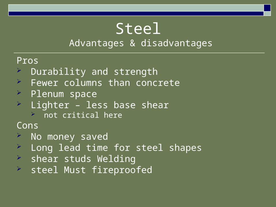
Steel Advantages & disadvantages
Pros Durability and strength Fewer columns than concrete Plenum space Lighter – less base shear
not critical hereCons No money saved Long lead time for steel shapes shear studs Welding steel Must fireproofed
Conclusion
Lessons learned

Is there a best option?
After weighing all of the designs…
Concrete
is the best optionWhy? Its advantages outweigh its disadvantages It is traditional for this type of project It is common for the area Cost is not much of an issue Durability is a greater requirement

a larger view
This study only applies to a single project, but it shows that:
There is a multitude of different criteria for different projects
There is a very close relationship between architectural development and structural scheme
The least expensive design is not always the best

Wrap up
Acknowledgements

Design team Owner – Eakin Youngentob Associates, Inc. General Contractor – Clark Construction Architect – Torti Gallas and Partners CHK, Inc. Structural Engineer – Cates Engineering, Ltd. MEP Engineer – Schwartz Engineering, Inc. Civil Engineer – Loiderman Associates, Inc. Landscape Architect – Parker Rodriguez

Thank you
Mike Stansbury, P.E.Dr. BoothbyDr. Hanagan
Dr. Ling
Any Questions?

The design
TYP. EXTERIOR WALLTRUSSES PERPENDICULAR
1/2" OSB WALL SHEATHING CONTINUOUS ACROSS TRUSSES
2x4 CONTINUOUS BAND
BRICK VENEER ATTACHED TO WALL STUDS WITH BRICK TIES AT 24" O.C. HORIZONTALLY AND VERTICALLY
WOOD STUDS SEE SCHEDULE
3/4" GYPCRETE TOPPING
23/32" PLYWOOD FLOOR SHEATHING
BUILT-UP HEADER. SEE PLANS FOR SIZE AND LOCATION
DOUBLE TOP PLATE
16" DEEP PREFABRICATED PLATE CONNECTED FLOOR TRUSSES
TYP. INTERIOR BEARING WALLPIGGY BACK TRUSS CONDITION
1/2" MAX CLR.
TOP CHORD BEARING TRUSS
16" DEEP PREFABRICATED PLATE CONNECTED FLOOR TRUSSES (LONGER SPAN)
DOUBLE TOP PLATE
23/32" PLYWOOD FLOOR SHEATHING
3/4" GYPCRETE TOPPING
WOOD STUDS SEE SCHEDULE

The designroof system
32” deep 2x6 single top and bottom chord metal plate-connected floor trusses
Based on deflection, moment of inertia, and span
Simple span condition throughout building
Rigid insulation on roof sloped to drain to avoid ponding
Bottom chord bearing
BUILT-UP HEADER. SEE PLANS FOR SIZE AND LOCATION
TRUSSES PERPENDICULAR
TYP. EXTERIOR WALL
BRICK VENEER ATTACHED TO WALL STUDS WITH BRICK TIES AT 24" O.C. HORIZONTALLY AND VERTICALLY
1/2" OSB WALL SHEATHING CONTINUOUS ACROSS TRUSSES
DOUBLE TOP PLATE
32" DEEP PREFABRICATED PLATE CONNECTED ROOF TRUSSES W/ 2x6 TOP AND BOTTOM CHORDS
SLOPE INSULATION 1/4" PER FOOT MIN.

The design
WIDE FLANGE BEAM TOP FLANGE COPEDSEE PLAN FOR SIZE
5" NORMAL WEIGHT CONCRETE TOPPING (f'c=4000)
3/4" x 4" SHEAR STUDS SEE PLAN FOR NUMBERINVERTED USD B-LOK DECK 18 GAGE - RIBS PERP. TO BEAM
WIDE FLANGE GIRDERSEE PLAN FOR SIZE
1/4" E70XX
BEAM - GIRDER CONNECTION
L4x3x3/8 SINGLE ANGLE SHEAR CONNECTION
3/4" A325-N BOLTS
WIDE FLANGE GIRDERSEE PLAN FOR SIZE
INVERTED USD B-LOK DECK 18 GAGE - RIBS PARALLEL TO GIRDER
3/4" x 4" SHEAR STUDS SEE PLAN FOR NUMBER
5" NORMAL WEIGHT CONCRETE TOPPING (f'c=4000)
1/4" E70XX
3/4" A325-N BOLTS
L4x3x3/8 SINGLE ANGLE SHEAR CONNECTION
GIRDER - COLUMN WEB CONNECTION