Embed Size (px)
Citation preview
Nanophotonics 2017; 6(1): 1–30
*Corresponding author: Maria Chernysheva, Aston Institute of Photonic Technologies, Aston University, Birmingham, UK, e-mail: [email protected] Rozhin: Nanoscience Research Group and Aston Institute of Photonic Technologies, Aston University, Birmingham, UKYuri Fedotov and Sergey M. Kobtsev: Division of Laser Physics and Innovative Technologies, Novosibirsk State University, Novosibirsk, RussiaChengbo Mou: Key Laboratory of Special Fiber Optics and Optical Access Network, Shanghai University, Shanghai 200072, ChinaRaz Arif: Physics Department, Faculty of Science, University of Sulaimani, Sulaimani, Kurdistan Region, IraqEvgeny M. Dianov: Fiber Optics Research Center of the Russian Academy of Sciences, Moscow, RussiaSergei K. Turitsyn: Aston Institute of Photonic Technologies, Aston University, Birmingham, UK
Edited by Volker Sorger
Review article Open Access
Maria Chernysheva*, Aleksey Rozhin, Yuri Fedotov, Chengbo Mou, Raz Arif, Sergey M. Kobtsev, Evgeny M. Dianov and Sergei K. Turitsyn
Carbon nanotubes for ultrafast fibre lasers
DOI 10.1515/nanoph-2015-0156Received December 20, 2015; revised March 11, 2016; accepted March 30, 2016
Abstract: Carbon nanotubes (CNTs) possess both remarka-ble optical properties and high potential for integration in various photonic devices. We overview, here, recent pro-gress in CNT applications in fibre optics putting particu-lar emphasis on fibre lasers. We discuss fabrication and characterisation of different CNTs, development of CNT-based saturable absorbers (CNT-SA), their integration and operation in fibre laser cavities putting emphasis on state-of-the-art fibre lasers, mode locked using CNT-SA. We dis-cuss new design concepts of high-performance ultrafast operation fibre lasers covering ytterbium (Yb), bismuth (Bi), erbium (Er), thulium (Tm) and holmium (Ho)-doped fibre lasers.
Keywords: carbon nanotubes; fibre laser; saturable absorber; sensing; nanostructures.
1 IntroductionMaterial science plays a critical role in the current explo-sive development of photonics providing new active and
nonlinear materials, low loss transparent or opaque media, and creating a platform for new applications, optical technologies and devices. Of particular impor-tance are nonlinear optical materials. Optical nonlinearity is exploited in various photonic applications, such as, e.g. switching, routing and regeneration of optical signals, as well as for generation of ultrashort laser pulses [1]. Femto-second lasers found applications in high-precision metrol-ogy of time and distance [2], spectroscopy [3], nonlinear optics and astrophysics [4] and many other applications [5–7]. In this review, we discuss carbon nanotube-based photonic technologies and applications making a particu-lar focus on mode-locking fibre lasers.
For ultrafast applications, nonlinear optical materials must possess a high nonlinear susceptibility and a fast recov-ery time. The majority of semiconductors offer such para-meters through a resonant band/state filling mechanism [8].
Basics of mode locking are well known [9]. Continuous wave (CW) radiation, typically, presents a superposition of longitudinal modes with chaotic phases, in general, leading to intensity fluctuations. The gain bandwidth defines a range of generated longitudinal modes and the average duration of fluctuation intensity spikes. Nonline-arity may result in synergetic phase locking (synchronisa-tion) of modes through nonlinear interactions (formation of stable nonlinear solitary wave pulses – solitons). In this case, in general, laser output consists of a train of pulses regularly spaced by a cavity round trip time Trep:
rep
L nTc⋅=
(1)
where L- is the cavity length, c- is the speed of light in the vacuum and n is the refractive index of the medium where light propagates [10, 11].
To realise phase locking of laser modes, a particular nonlinear element has to be incorporated into the cavity to act as an intensity discriminator: suppressing low-amplitude fluctuations and supporting higher-intensity spikes. This function can be implemented using optical nonlinearities both by using nonlinear effects (such as, e.g. Kerr-lens, nonlinear loop mirror dynamics or non-linear polarisation evolution) or applying materials with
©2016, Maria Chernysheva et al., published by De Gruyter. This work is licensed under the Creative Commons Attribution-NonCommercial-NoDerivatives 3.0 License.Brought to you by | Aston University Library & Information
AuthenticatedDownload Date | 12/21/16 1:37 PM

2 M. Chernysheva et al.: Carbon nanotubes for fibre lasers
appropriate properties enabling ultrashort pulse forma-tion through passive mode locking [10, 11]. Numerous works aimed to explain pulse formation in the passive mode-locked laser [12–16], using in particular so-called fluctuation model [17, 18]. The material saturable absorber, for instance, may exploit the property of the incident light of sufficient intensity to fill up upper energy states [8]. Then, according to the Pauli principle, multiple car-riers cannot fill the same energy states. Thus, the further optical transition will be blocked, resulting in the satura-tion of optical absorption. The material will suppress the low-intensity light by transmitting a high-intensity one. Such nonlinear materials operate as a saturable absorber (SA) and can be used to produce short pulses in lasers.
First studies on passive mode locking were carried out in 1960–1970s with solid state and dye lasers [19]. The achieved pulse duration in latter ones was < 100 fs [20]. However, due to low efficiency, complexity and the heavy gauge, dye lasers could not be applied out of labo-ratory conditions. On the contrary, fibre lasers [21], which emerged in 1961, benefit from the maintenance-free opera-tion, compactness and cost-effective design.
The nonlinear optic Kerr-lens (KL) effect, based on the dependence of the refractive index on intensity (peak power), first proposed in 1975 [22], is now widely in use for laser mode locking [7, 10]. The main advantage of this technique is ultrashort time response, which is of the order of a few femtoseconds [11, 23, 24]. The cavity align-ment is critical in the KL method, with a tolerable margin within several 100 microns [23]. In fibre lasers, nonlinear polarisation evolution (NPE) and nonlinear optical and amplifying loop mirrors are also used as effective satura-ble absorber elements [25, 26]. However, in these methods, typically, mode-locked lasers should operate close to sta-bility threshold [23] making stable operation challenging.
Most commonly used material SAs are the III–V group binary and ternary semiconductors in the form of multi-ple quantum wells (MQW), grown on a distributed Bragg reflector [23, 27, 28]. These are so-called semiconductor saturable absorber mirrors (SESAMs). Generally, SESAMs possess a recovery time in the nanosecond time range [5]. To reduce the recovery time down to a few picoseconds, MQW structures should maintain a significant amount of carrier trapping defects. Methods, allowing this to be achieved, are low-temperature molecular beam epitaxy growth of the MQW or, alternatively, utilising post growth ion implantation [5, 28]. By the start of the 1990s and until now, the SESAMs were used for mode locking of solid-state lasers in a broad spectral range between 800 nm and ~2 μm to generate sub-100 fs pulses [5, 28]. However, a fab-rication and mounting of SESAMs in laser cavity typically
requires costly procedures. More important, for applica-tion in the short-wavelength infrared region, i.e. for a wavelength band longer than 1.3 μm, a higher indium con-centration is required. In its turn, a high indium concen-tration gives a rise to highly strained layers on GaAs-based Bragg mirrors and, therefore, decreases the quality of the surface and increases non-saturable losses [29]. Thus, new materials with strong ultrafast optical nonlinearities, broad-operating spectral range, simple processing and device packaging are still in high demand.
Recently, transition metal dichalcogenides (TMDs), with the general formula MX2, where M is a transition metal, and X is a chalcogen [30], have renewed research interest. They possess remarkable layer-dependent optoelectronic properties, strong photoluminescence, high nonlinear-ity and ultrafast carrier dynamics for mono- and few-layer forms [30] and Dirac-like linear band dispersion [31]. The first saturable absorption behaviour was demonstrated at the 1550-nm wavelength range [32]. Shortly after that, Zhao et al. presented the achievement of ultrashort pulse gen-eration in the fibre laser mode locking by the TMD-based SA [33]. Further investigations with the Z-scan technique showed that the TMDs also possess large nonlinear refrac-tive index [34]. Thus, the TMDs could serve as both the high nonlinear photonic device and the SA in the laser system.
During the past decade, carbon nanotubes (CNTs) became a popular SA of choice, in many senses taking the place of SESAMs [35–38]. Being first synthesised as a by-product of fullerene production [39], CNTs have gained high attractiveness for novel electronics and photonics device development due to their unique features [40]. In 2003, single-walled CNTs (SWNTs) were applied in Er-doped fibre laser for passive mode locking for the first time [41]. SWNTs are a promising candidate for the ultrashort pulse generation because they possess ultrafast excited state carrier dynamic and high optical nonlinearity [42–44]. Semiconductor SWNTs (s-SWNTs) are a direct bandgap material having a series of van-Hove singularities in the density of state. The SWNTs band gap depends on the tube diameter [20]. By growing nanotubes with a proper diam-eter distribution, it is possible to set absorption peak posi-tions in a broad spectral range between visible and near-IR [20]. Additionally, theoretical calculations predicted a high third-order polarisability χ(3), where values are two orders of magnitude greater than for GaAs superlattices commonly used in telecommunications [45]. Spataru et al. [46] reported a theoretical estimation of intrinsic exciton lifetime of about ~10 ps for lowest bright excitons in iso-lated SWNT. However, a recent photoluminescence study of small bundles in solution shows that exciton energy transfer between semiconducting SWNTs within bundles
Brought to you by | Aston University Library & InformationAuthenticated
Download Date | 12/21/16 1:37 PM

M. Chernysheva et al.: Carbon nanotubes for fibre lasers 3
can be an efficient carrier relaxation channel [47]. The multicomponent carrier recombination dynamics inher-ent to nanotubes comes from (i) intraband thermalisation (with relaxation time of 200 fs) [48], (ii) exciton energy transfer between adjacent tubes in bundles [47], (iii) non-radiative recombination through dark excitonic states and excited carrier tunnelling on metallic tubes (m-CNTs) (500 fs–10 ps) and (iv) the radiative recombination through bright excitonic states (10–500 ps) [41, 49].
There are numerous reports in the literature [50–67] on the use of SWNTs as mode lockers and Q-switches for ultra-fast lasers in the broad wavelength band, which are summa-rised in Table 1. One of the main advantages of SWNT-based SAs, apart from ultrashort relaxation time and high nonlin-earity, is the ease of their fabrication and implementation into the laser setup. Typically, SWNT-based SAs are made of a solution [54, 64], or deposited on the surface of optical parts [53, 55] or SWNT-polymer composites [57–59, 61, 66], which will be discussed hereafter in detail.
There are several review papers, focused on photonic properties of carbon nanotubes, unlock their potential for application in ultrafast lasers as SA [35, 37, 38, 40]. In view of these trends, this review is dedicated to the tremendous development of the last 4 years, since the latest review paper, and challenges us to foresee future technological and scien-tific growth in the field. Portraying the whole process from fabrication, characterization and implementation together in the fibre laser cavity, we provide the insight into exciting possibilities of CNT-based SA and, hence, deliver a complete interdisciplinary package for future research or an introduc-tion to the field. The plan of the paper is the following: the first section is focused on CNT production, purification and dispersion into hosting polymers; in the second section, we discuss CNT/polymer film characterisation via most informative techniques; then, we review common methods for CNT-based SA implementation into a fibre laser cavity; the last section encompasses remarkable design concepts for the present-day, high-performance ultrafast fibre lasers, concluding with an overview of current research directions and possible outcomes.
2 CNT-SA fabrication
2.1 CNT synthesis
2.1.1 Arc discharge method
The arc discharge method is the first established proce-dure for CNT production. It was initially developed for C60
fullerenes and later transformed for multi-wall carbon nanotubes (MWNTs) [73] and SWNT fabrication [74, 75]. Typically, the arc discharge method uses arc vaporisation of two carbon electrodes placed a small distance from each other, ~1–2 mm in a cavity filled with inert gas at low pressure or liquids. High-temperature electrodes (~4000–6000 K), due to resistive heating, facilitates the break-down of the surrounding medium (gas or liquid), filled the chamber. The medium ionisation results in plasma formation between the electrodes. The high temperature of anode sublimates carbon and evaporates it. The carbon vapours are disintegrated in carbon ions due to thermal energy in plasma. The carbon gases move along the tem-perature gradient towards the relatively cool cathode, condense into liquid carbon and later crystallises, forming rod-shaped deposition on the cathode, composed of CNTs [76]. However, the process of CNT formation is still questionable. Thus, there are several theories on growing mechanism [75, 77].
One of factors affecting CNT growth is the presence of catalysts. In [78], it was experimentally shown that the presence of metal catalyst favours SWNT growth, rather than MWNTs, whereas the size of the catalyst deter-mines the diameter distribution. Both Ni and Fe can help increase yield and quality of SWNTs production. There-fore, Gamaly and Ebbesen [79] demonstrated the appli-cation of electrodes with bored holes, filled with Fe, Ni, Co metals, and the chamber filled with 100–500 torr of helium (Figure 1A). Though Fe helps to increase the length of nanotubes, it forms its oxide Fe2O3, which complicates CNT production. Thus, the Fe concentration should not exceed 10% for CNT formation [85]. However, in the case of a binary catalyst, Fe also forces MWNT formation. For that reason, in [86], Zhao et al. suggested to use sulfur in addition to Fe for DWNT production.
The temperature in the chamber mostly depends on the arc current and thermal properties of the medium, as a plasma of individual gas or liquid generates a dif-ferent temperature. The influence of the temperature on CNT formation is still questionable. Several recent papers suggest distinctive optimum temperature for both SWNT and MWNT [43, 82].
First experiments utilised a pressurised chamber filled with 10 torr of methane and 40 torr of argon gas mixture, which allowed nanotube production with diameters ranging between 0.7 and 1.65 nm and a length of 1 mm [39]. Nevertheless, the arc discharge method utilising the gas medium is very expensive as it requires the application of noble gases and gas-handling vacuum equipment. Moreover, it operates at a high temperature and, hence, requires the proper
Brought to you by | Aston University Library & InformationAuthenticated
Download Date | 12/21/16 1:37 PM

4 M. Chernysheva et al.: Carbon nanotubes for fibre lasers
Tabl
e 1:
Pro
gres
s in
fibr
e la
sers
mod
e lo
cked
by
carb
on n
anot
ubes
.
Lase
r typ
e CN
T SA
type
Pu
lse
dura
tion
Repe
titio
n ra
te
Aver
age
pow
er
Puls
e en
ergy
Pe
ak p
ower
Ye
ar
Refe
renc
es
Ytte
rbiu
m
Tape
red
CNT
23
5 fs
15
5 m
W
–
3 nJ
–
20
08
[50]
PV
A-ba
sed
film
2–
3.8
ps
–
1.5
mW
0.
03 n
J
15–7
.9 W
20
12
[51]
D-
shap
ed fi
bre
94
1 fs
35
mW
–
0.
93 n
J
0.2
kW
2014
[5
2]
Optic
al d
epos
ition
CNT
13
7 fs
0.
1 m
W
–
5 pJ
–
20
07
[53]
Erbi
um
Poly
mer
film
: lin
ear
1.
1 ps
0.
26 m
W
6.1
MHz
–
Ring
cavi
ty
318
fs
0.79
mW
9.
85 M
Hz
–
–
2004
[5
4]
Optic
al d
epos
ition
CNT
82
0 fs
–
5.
2 M
Hz
–
–
2010
[5
5]
PVA-
base
d fil
m
713
fs
8 m
W
–
1.6
nJ
2.24
kW
20
06
[56]
SW
NT/P
3HT
casc
adab
le
113
fs
5 m
W
42 M
Hz
–
–
2010
[5
7]
CMC
film
17
7 fs
7
mW
–
0.
14 n
J
0.79
kW
20
08
[58]
Ho
llow
fibr
e fil
led
with
SW
NT
490
fs
4.5
mW
18
.5 M
Hz
–
20
09
[68]
CM
C-ba
sed
poly
mer
film
(hyb
rid M
L with
PZ
fibre
-bas
ed N
PE m
odul
ator
) 92
fs
11.2
mW
–
0.
3 nJ
2.
9 kW
20
15
[59]
Bism
uth
Bi
-Er r
ing
film
46
0 fs
5
mW
–
44
8 pJ
1
kW
2013
[6
0]
CoM
oCat
CNT
PVA
(AND
i reg
ime)
4.
7 ps
10
–15
μW
5 M
Hz
–
–
2010
[6
1]
CNT
depo
site
d on
silv
er m
irror
2.
1 ps
1.
5 m
W
–
Afte
r am
plifi
catio
n
240
fs*
15
mW
*
20 M
Hz
–
3.1
kW*
20
15
[62]
Thul
ium
CM
C fil
m
1.32
ps
3.
4 m
W
–
0.09
2 nJ
70
W
2008
[6
9]
CMC-
base
d fil
m+N
ALM
45
0 fs
18
mW
–
0.
4 nJ
62
5 W
20
12
[70]
Ta
pere
d fib
re
750
fs
25 m
W
–
0.5
nJ
–
2009
[6
3]
PVA-
base
d po
lym
er fi
lm (h
ybrid
ML w
ith N
PE m
odul
ator
)
500
fs
117
mW
9
MHz
10
.87
nJ
21.7
kW
20
14
[71]
DW
CNT
2014
[7
2]
DWCN
T po
lym
er fi
lm
560
fs
99.4
mW
–
1.
66 n
J
2.96
kW
20
15
[66]
Tm:H
o
Spra
yed
on m
irror
1
ps
15 m
W
41 M
Hz
–
–
2009
[6
4]Ho
lmiu
m
CNT
spra
yed
on m
irror
89
0 fs
45
mW
–
2.
87 n
J
3.22
kW
20
12
[65]
*Val
ues
afte
r am
plifi
catio
n.
Brought to you by | Aston University Library & InformationAuthenticated
Download Date | 12/21/16 1:37 PM

M. Chernysheva et al.: Carbon nanotubes for fibre lasers 5
Figure 1: Schematic setup of CNT fabrication techniques: (A) arc-discharge process; (B) laser ablation; (C) CVD method; (D) HiPco process; (E) CoMoCAT technique. Adapted from [80–84].
liquid-cooling system. It is essential for high-quality CNT production as it prevents the sintering effect. On the contrary, utilising the arc plasma in liquids is a very simple process, allowing low-cost high-yield CNT pro-duction. First introduced in 2001, the electric arc dis-charge in a liquid medium used water [87], followed by molten lithium [88] and liquid nitrogen [89] and deion-ised water [90]. However, deionized water possesses excellent electrical insulating parameters. Thus, the arc discharge is not stable. Conversely, a salt solution improves electrical conductivity [90].
The result of the discharge, including diameter dis-tribution and formation of CNT bundles, depends on the temperature and uniformity of the plasma arc [91]. The diameter distribution of forming CNTs is determined with the density of carbon vapours in plasma. Moreover, the pressure of inert gas determines the structure of the carbon product. For example, at the pressure of 1000 torr, carbon onions are produced, whereas the pressure decrease down to 500 torr allows the formation of nanotubes. Further, a decrease down to 100 and 20 torr results in fullerene and amorphous graphite production, correspondingly [91].
Furthermore, it was found that the type of electric current affects the CNT growing process. According to Ashraf et al. [92], continuous arc discharge favours diatomic carbon clusters C2 formation, which is essential for nanotube orig-ination, whereas pulsed arc produces monatomic clusters C1. For applied DC CNTs deposit on the cathode. However, for AC deposition is obtained on sidewalls of the reactor chamber, as the polarity of electrodes changes every cycle. The short-pulse AC discharge is more energetic compared to DC. Hence, its utilisation increases the yield and allows more control over the process.
In conclusion, the arc discharge method is one of simplest ways, allowing low-cost production of CNTs. However, it suffers from the broad diameter distribution of produced CNTs, presence of bundles, soot and residual catalytic particles in the final product.
2.1.2 Laser ablation
First introduced in 1995, the laser ablation process uses a pulsed laser, which hits a graphite target in the
Brought to you by | Aston University Library & InformationAuthenticated
Download Date | 12/21/16 1:37 PM

6 M. Chernysheva et al.: Carbon nanotubes for fibre lasers
high-temperature reactor in the presence of inert gas [93]. An inert gas carries carbon vapours along the tem-perature gradient from the high temperature into a cooled collector positioned downstream (Figure 1B). Out of evaporated graphite, carbon nanotubes are formed and deposited on the chamber wall. Produced nanotubes are bundled, aligned along a common axis and form a mat of ropes. Ropes’ diameters range between 10 and 20 nm and possess a length up to 100 μm. The yield of SWNTs out of the carbon consumed by laser ablation is more than 70% [94]. Compared with the above-described arc discharge method, laser ablation CNTs were purer (up to 90% purity) as well as possessed a narrower diameter dis-tribution, due to the control by varying the temperature, catalyst composition and laser parameters.
In pioneer experiments, two consecutive laser pulses were used: the first one – for initial evaporation and the second one – to accelerate and uniform graphite evapora-tion process [95]. This method helped to increase the yield of the process and decrease the amount of deposited soot. Another approach showed CNT formation using CW laser radiation [96].
Analogous to the arc discharge method, laser abla-tion also utilises catalysts to grow tubes on their atoms [97, 98]. Otherwise, laser ablation of graphite produces fullerenes [99]. Catalysts are essential in nanotube for-mation as their atoms prevent the closing of the fullerene by attaching additional carbon particles. A single atom or group of atoms adsorb carbon molecules transform-ing them into rolled graphene-like sheets until too many catalyst atoms accumulate at the end of the nanotube. This results in tube termination with a fullerene cup or atom of catalyst [93, 94]. The comprehensive investigation showed a strong effect not only on diameter distribution and yield but also on microstructure and morphology of deposited carbon nanoparticles. The first and most appli-cable catalysts are Ni, Fe and Co and their 1:1 mixture [98]. It is worth noticing that bimetallic catalysts are more pro-ductive [100]. Application of other catalytic particles, for example, platinum, sulfur, molybdenum or yttrium, did not demonstrate high-yield or high-quality CNT forma-tion. Moreover, Ref. [97] demonstrated that mixing the vapour or clusters of catalytic metal particles and carbon in an inert gas atmosphere could increase the yield of nanotubes. One of the proposed methods to achieve this is the double-target technique, which applies two semi-cylinder targets of C and Ni with Co, placed face-to-face trough a quartz glass plate. It was shown in Ref. [97] that one laser-ablated target of C, Ni and Co changes its com-position during carbon vaporisation, whereas the double target provides a stable Ni:Co composition and, hence,
production of uniform SWNT. The separately controlled hitting of carbon and catalysts targets provides additional improvements in this technique.
Several studies on temperature variation have been carried out. A high temperature increases the collision rate between carbon particles and, therefore, assists mass transportation of carbon clusters [101]. Furthermore, high kinetic energy limits the cooling rate of carbon particles and, hence, forces the decomposition of some large clus-ters into proper precursors for nanotube growth [94]. The high temperature enhances the activity of the metal catalyst. This results in nanotube diameter increase at a higher temperature [102]. However, it was demonstrated that CNT growth is controlled by both the availability of proper precursors and the activity of the catalytic metal particles rather than temperature [103]. Moreover, a high temperature forces fullerene formation.
2.1.3 Chemical vapour deposition
Since the first demonstration in 1996 by Li et al. [104], the chemical vapour deposition (CVD) method is the most promising technique for the large-scale production of CNTs. In the beginning, the CVD method was widely used for fullerene and carbon nanofibre formation, though it produced a high amount of defects in tubular carbon nanoparticles. CVD nanotubes feature a small diameter distribution in the range from 1 to 3 nm and high aspect ratios of more than 104. Moreover, such SWNTs benefit from smooth curving and the small amount of topological defects along sidewalls [105].
During the CVD process, the patterned substrate is heated in the chamber filled with inert gas (Figure 1C). The gas of carbon feedstock flows into the chamber to replace the inert gas until the furnace cools to room temperature [105]. The growing process of nanotubes includes absorp-tion, decomposition of carbon feedstock on catalytic par-ticles and diffusion of carbon particles into catalysts from a supersaturated catalyst surface. The “base-growth” is the dominating mechanism for SWNT materials [106]. A nanotube lengthens with a particle-free closed end, and the other end of nanotube interfaces with the catalyst material.
The CVD method utilises a mixture of hydrocarbon gas and process gas (nitrogen, hydrogen or ammonia), which react in a chamber on a substrate, heated to the temperature of 700–900°C. For the carbon source gas, several hydrocarbons were studied, for example, methane [105], ethylene [107], benzene [108] or the most recent one, camphor (C10H16O), which moreover appeared
Brought to you by | Aston University Library & InformationAuthenticated
Download Date | 12/21/16 1:37 PM

M. Chernysheva et al.: Carbon nanotubes for fibre lasers 7
to be environment friendly [109]. A substrate is covered with catalytic metal particles, like Fe, Ni, Co or their com-bination. Patterning the substrate with catalysts allows SWNT growth at a particular position. After the reaction, catalysts stay on the top or at the bottom of produced CNTs.
Numerous works aimed to find appropriate conditions for SWNT production. The first step was done by choos-ing a suitable carbon feedstock [105, 106]. For example, methane, being stable at high temperatures over 1000°C, is protected against self-pyrolysis and, therefore, amor-phous carbon formation [110]. Moreover, the decomposi-tion of methane over the formed nanoparticles prevents their further growth and, hence, results in a higher yield of SWNT compared with the amount of MWNT [91]. The high-temperature operation during a long time scale forces amorphous carbon over-coating to sub-micrometre thickness. Thus, the time of CVD process is usually limited to 10 min [106].
Analogous to previously discussed CNT produc-tion methods, catalysts play the critical role in the CVD process, determining the yield and type of final carbon products. In [110], it was shown that pore structures of a catalyst strongly influence diffusion rates of molecu-lar species and, therefore, control the reaction kinetics. Porous materials are ideal for self-orientation of nano-tubes on large surfaces. Moreover, better metal deposition on the substrate leads to the higher density of catalysts and defuses efficiently of reactant and product molecules, yielding desired results [110]. Furthermore, diameters of produced CNTs match the size of metal catalyst particles on the heated substrate at the moment of carbon source gas flows into the reaction chamber.
The on-going research of the CVD process has intro-duced various modifications, for example, low-temper-ature CVD [111] and plasma-enhanced CVD (PECVD). The water-assisted or low-temperature CVD allows the increase in catalytic particles’ lifetime, producing the so-called “forests”, which are dense perpendicular to sub-strate and have the length up to 2.5 mm.
PECVD is advantageous for low-temperature forma-tion of highly aligned CNTs with predetermined geometry [82]. More important PECVD enables selective growth of s-SWNTs [82]. The strong electric field in the plasma creates individual and vertically freestanding nanotubes [112]. However, nowadays, the formation of CNTs in the PECVD process is still not clear. There are many uncon-trolled parameters such as ion density, ion energy, radical species, radical densities, which are under thorough investigation. Certain plasma effects might increase cata-lyst particle aggregation, high-energy ion bombardment,
hence, limiting SWNT formation and forces MWNT pro-duction. To solve this problem, diffusion plasma was used to decrease the ion energy. As a result, SWNTs were pro-duced under the diffusion plasma on the flat substrate without any of catalytic particles [113].
Arc discharge and laser ablation are simple and, there-fore, widely used methods though allowing to obtain only small amounts of high-quality CNTs. As they are based on a carbon evaporation technique, their product cannot be scaled for mass production purposes, in particular. The other drawback is low quality of carbon deposition, containing amorphous graphite, tangled forms, bundles and catalyst particles besides desirable SWNTs [91]. Con-sequently, chemical methods are considered to be more promising.
2.1.4 High-pressure carbon monoxide reaction (HiPco)
Above-described methods utilised hydrocarbons as carbon source gases. However, amorphous graphite over-coating or graphitic products of hydrocarbon pyrolysis limit high-yield and high-quality CNT formation at high temperatures. These obstacles forced application of other gases. The novel method, called high-pressure carbon monoxide reaction (HiPco), utilises carbon monoxide CO, as a carbon feedstock [114]. In this method, Fe(CO)5 is injected into a CO gas at high temperature and high pres-sure, promoting the Boudouard reaction:
2CO CO ( ) CO (g)C s+ = + (2)
Figure 1D presents the schematic of the HiPco setup. It consists of a narrow tube, through which hot CO vapours and cold Fe(CO)5 and CO gases flow in opposite directions. The temperature inside the furnace is kept between 800°C and 1200°C. The water flow cools cold gases on their way to the furnace, where they undergo rapid heating. On the contrary, hot CO gas passes through the spiral heat exchanger within the furnace and is sprayed through a circle of narrow-gauge needles. Such temperature differ-ence and the speed of heating results in the SWNT forma-tion preferable to other carbon forms and increases their length [114].
Controlling parameters of the gas flow, Yakobson et al. achieved the formation of the SWNT with a diam-eter of 0.7 nm. This value is about the diameter of a C60 fullerene and supposed to be the smallest stable SWNT, achievable chemically [115]. Chiang et al. explained the CNT formation during the HiPCO method as follows: metal clusters achieve a size of C60 fullerenes with the diameter of about 1 nm and nucleate. Being a more
Brought to you by | Aston University Library & InformationAuthenticated
Download Date | 12/21/16 1:37 PM

8 M. Chernysheva et al.: Carbon nanotubes for fibre lasers
stable carbon particle, CNTs grow around catalyst clus-ters [116].
Pioneer works have shown that temperature and pressure increase (up to 50 atm) rise production rate and yield of SWNT [117]. At higher pressures, CO molecules disproportionate faster, resulting in the formation of more C atoms on each Fe cluster and faster SWNT nuclea-tion relative to continued particle growth. Moreover, produced SWNTs possess smaller diameters as pressure increases [116].
Compared to hydrocarbons used in arc discharge or laser ablation methods, the CO as a carbon source gas disproportionates much slower. In [114], the use of the mixture of CO with the small amount of methane (0.7%) has been demonstrated. This method helped to increase the yield of SWNTs, though higher concentrations gave amorphous carbon overcoating or required lower produc-tion temperatures. In other works, a mixture of benzene and ferrocene [108], metallocenes in an admixture with C2H2 [118], CO and CO/H2 [119] or Fe(C5H5)2 [120] was sug-gested as a carbon feedstock. Moreover, ultralong SWNTs of 10–20 cm length have been synthesised by Zhu et al. using a hexane solution of ferrocene and thiophene with hydrogen as the carrier gas [121]. The Young’s modulus of these SWNTs ranged from 49 to 77 GPa.
2.1.5 Cobalt and molybdenum (CoMo) CAT process
In 2000, a new method utilising cobalt and molybdenum catalysts and CO as a carbon source gas (CoMoCAT) was developed by Kitiyanan et al. [122]. Since very first experi-ments, the CoMoCAT method appeared to be promising and fruitful, allowing to produce about 0.25 g SWNT/g catalyst in a couple of hours. The amount of SWNT could reach 80%.
This method is based on the CO decomposition described by the Boudouard reaction (2). The temperature of the CO gas usually ranges between 700°C and 950°C with the pressure from 1 to 10 atm. The presence of Mo on the same substrate limits Co sintering before the reac-tion. After the reaction of CO disproportionation begins, Mo oxide transforms into Mo carbide, which cannot restrict Co metallization [91]. Metallic Co particles being dispersed in the chamber hit CO molecules. CO molecules decompose and nucleate until a certain configuration and carbon surface concentration are obtained for CNT formation (Figure 1E). The configuration of this so-called embryo determines the diameter of the future nanotube. The following formation of CNTs by incorporation of carbon onto the embryo is extremely fast and takes several
milliseconds, whereas the whole CoMoCAT process can last for hours [84]. With the temperature growth (up to 850–950°C), larger metal clusters are formed on the cata-lyst surface, which cause the production of nanotubes with larger diameters.
Initially, silica substrate has been utilised for the CoMoCAT process, as it features lower affinity of silica for the Co and Mo ions, therefore, facilitating the Co-Mo inter-action. Another research was focused on the application of the aluminium substrate, and found wide application in industrial production [123].
The presence of two simultaneous catalysts Co and Mo is essential for CNT formation. Mo forms small clus-ters of well-dispersed Mo6+ particles, which interact with Co, forming a Co-molybdate-like structure. Under reaction conditions, Mo oxide species are converted into Mo carbide, releasing the metallic Co in a state of high dispersion, which forces the formation of SWNT [123]. Otherwise, in the case of the presence of Co only or at a high Co:Mo ratio interacts into a nonselective Co3O4 phase, which further reduces to metallic Co. Large metallic Co clusters handle the forma-tion of MWNT, filaments, graphite and other side products. This makes catalysts unselective [124]. The other case is the presence of Mo only catalytic particles or low Co:Mo ratios, which creates inactive catalysts.
All currently known synthesis methods cannot provide pure CNTs; the product usually contains impuri-ties like catalytic particles, amorphous graphite, fuller-enes, etc. Here, we just briefly discuss proposed methods to separate desired CNTs from the raw products and improve surface area, including oxidation, ultrasonication, acid or thermal treatment techniques and micro-filtration.
Ultrasonication technique is based on the separation of agglomerates of different nanoparticles due to ultra-sonic vibrations. When an acid is used, the purity of CNTs depends on the sonication time. During the tube vibration to the acid for a short period, only the metal is solvated, but in a more extended session, CNTs are also chemically cut [125, 126].
As it follows from the name, during oxidation, CNTs and impurities are oxidised. Impurities, which are, in general, metals of catalysts get damaged at a higher rate, than CNTs. The yield of the oxidation process depends on metal content, oxidation time and agents and environment [127].
Micro-filtration rests on particle size: bigger parti-cles are trapped in a filter, whereas small particles like catalyst metal, fullerenes and CNTs pass through the filter [125]. The other version of micro-filtration is cross flow filtration. The filtrate is pumped down at the head pres-sure from a reservoir, and the fast-flowing suspension is
Brought to you by | Aston University Library & InformationAuthenticated
Download Date | 12/21/16 1:37 PM

M. Chernysheva et al.: Carbon nanotubes for fibre lasers 9
returned to the same reservoir to be cycled through the fibre again [127].
For acid treatment, different acids were studied. The nitric acid HNO3 was found to affect the metal catalyst only, showing no selectivity on the CNTs and the other carbon nanoparticles, whereas the hydrochloric acid HCl showed a little impact on the CNTs [126].
Temperature plays a critical role in all of these pro-cesses, determining their efficiency and yield. During the thermal treatment, the metal clusters are melted and can be easily removed [126].
The choice of SWNTs for saturable absolution appli-cation is usually conditioned by available semiconduc-tor SWNTs with an energy band resonantly matching the operation wavelength-specific fibre laser. As an example, CoMoCaT SWNTs of small diameters (0.7–1.1 nm) perfectly works in Yb and Bi-doped fibre lasers [51, 61]. At the same time, HiPco tubes are very efficient for Er, Pr, Bi-doped fibre lasers [62, 128, 129]. Finally, SWNTs grown by the laser ablation method usually have a narrow diameter up to 1.4 nm distribution and can be applied for Er, Tm, Ho-doped fibre lasers [56, 71, 129].
2.2 CNT separation
Most of the advanced CNT applications, especially in electronics, require that their well-defined structures and electrical properties can be achieved in the case of the uniform CNT geometry in the sample, i.e. length, conductivity type, diameter and chirality. The first approach of the selective growth of CNT was realised by the controlled CVD method [82, 130]. Later, numerous works were focused on the production of single geom-etry nanotubes [130–132]. However, presented methods are very complicated and cannot be used for mass production.
Therefore, nowadays, the CNT separation is widely used, for example, using electrical breakdown [133], chemical reagents [134] and laser or microwave radiation [135]. Though these techniques result in the destruction of removed particles. The other way to achieve high-purity solutions of both m- and s-CNTs, numerous post-growth techniques presented below in detail have been developed.
The selective chemical functionalization is based on different patterns of the interaction of CNTs with sur-factants, polymers, DNA and organic molecules, depend-ing on their electronic properties, diameter and chirality. It falls into four main categories: (i) covalent reaction on sidewalls, (ii) covalent reaction on defects and open tube
Figure 2: Types of chemical functionalisation: (A) covalent func-tionalisation; (B) endohedral functionalisation; (C) non-covalent polymer wrapping; (D) non-covalent functionalisation.
ends, (iii) non-covalent functionality with surfactants and (iv) non-covalent polymer wrapping or molecule adsorption into tubes (Figure 2). The covalent reaction on sidewalls allows selection by the conductivity type and diameters.
If the curvature of a CNT surface is neglected, the density of states (DOS) of CNT is characterised by van Hove singularities [136]. Singularities present a set of δ functions, symmetrically located with respect to the Fermi level. The CNT diameter determines the distance between singularities. The dependence of the electronic structure of CNT on the geometry can be explained using the DOS model. Only discrete values of the vertical component of the wave vector k, which fulfil the condition of continuity wave function along the tube circumference:
dmπ
λ⊥ =
(3)
Here, λ- is the wavelength of the wave function along the CNT circumference, d- is the CNT diameter. The DOS model proves that only dipole-allowed optical transitions can occur between symmetrical singularities, i.e. transitions with the absorption of photons with energies E11, E22, E33, … between valence and conduction bands (Figure 3).
Metal CNTs possess a higher reactivity due to a higher DOS at the Fermi level and lower ionisation potential. Dis-tinctive reactivity was first demonstrated in [137] using diazonium halide as an electron-withdrawing reagent to separate m-CNT from s-CNT. On the contrary, salts of ben-zenediazonium showed higher reactivity for s-CNT with smaller diameters [138]. Later, the list of chemicals, suita-ble for the covalent chemical reaction has been advanced [139, 140].
Brought to you by | Aston University Library & InformationAuthenticated
Download Date | 12/21/16 1:37 PM

10 M. Chernysheva et al.: Carbon nanotubes for fibre lasers
On the contrary to the irrepressible chemical reac-tion during covalent functionalization, non-covalent CNT functionalization retains the sp2 structure of CNTs, preserving their electronic properties [141]. In [142] Nish et al. proposed that both relative orientation of CNT and polymer chain determine the conformation of the polymer around tubes along with electron exchange in the case of m-CNTs. It was observed that π-π interactions between the graphite sheet and the aromatic component amphiphilic molecule include both electrostatic and van der Waals interactions [143]. Hence, polymers containing aromatic moieties appeared to be efficient adsorbents onto the graphite surface [144].
Interaction of s-CNT with chemical or biological com-pounds such as DNA molecules allows the selection of a wide range of diameters and chirality [145, 146]. Aside from that, the protein and DNA binding to CNT is very fruitful for medicine, as CNTs can deliver the medical drug, peptides, nucleic acids, crossing cell membranes [147]. Methods based on such interactions referred to as chromatography, include anion exchange chromatogra-phy (AEC) [146], size-exclusion chromatography [148] and electrokinetic chromatography [149]. DNA-coated CNT solutions benefit from high stability in the time domain; they stay stable for months at room temperature [150]. Though, due to the limited length of wrapping DNA mole-cules, the method is suitable for CNTs, when the diameter does not exceed 1.2 nm.
Electrophoresis allows CNT separation by their physical and electronic properties [151]. Constant current induces CNT geometry-dependent transfer through the dispersion, making smaller diameter or shorter CNTs propagate faster. By the combination of electrophore-sis with selective functionalization using electron-with-drawing reagents, two fractions can be collected. s-CNTs
Figure 3: Example of the CNT density of states.
remain at the central part of the suspension, whereas m-CNTs move to the cathode. In its turn, during dielectro-phoresis, the launched alternating current results in the opposite transfer of s- and m-CNT along the field gradient towards microelectrodes [152]. However, dielectrophoresis is a very low-yield method, about 10–12 g.
Gradient ultracentrifugation is based on the analysis of hydrodynamics of a complex system of CNT and sur-factant [153]. It allows diameter and chirality selection, as well as separation of s- and m-CNT [154]. The surfactant forms a gradient of density, similar to one of CNTs. Indi-vidual CNTs migrate into surfactant layers matching their density during the ultracentrifugation process (with acceleration g > 100,000). Assuming that the surfactant interacts with all dispersed CNTs equally, irrespective of their conductivity type or geometry, the buoyant density of the resulting suspension depends only on CNT diam-eter [155]. To achieve selection by conductivity type, one should apply two surfactants with both different density and reactivity for either s- or m-CNTs. For example, in a pioneering work, Arnold et al. used sodium cholate as an effective surfactant and iodixanol as a density gradient solution [156]. High-density lower layers of the disper-sion contain m-CNT, possessing higher reactivity, whereas s-CNTs reside in the upper layer. The purity of the metal fraction of the CNT in this method reaches 99% [153]. Yanagi et al. [157] demonstrate suspensions of high-purity separated geometries of m-CNTs with diameters of 1.34, 1.0 and 0.84 nm, which featured three different colours: cyan, magenta and yellow, correspondingly. Yanagi et al. also reported the dependence of the centrifuga-tion process on temperature conditions using sucrose as a density gradient medium [158]. They showed that with temperature decrease, the purity of the separated layers becomes higher.
Surfactants not only interact with the sidewalls of the nanotube but can also soak through the tube that makes a huge impact on the resulting density of suspension [159]. Therefore, another reason to apply two surfactants simul-taneously is the different reactions for CNT [160]. In [161], two different types of the solution consisting of sodium deoxycholate (DOC) and sodium dodecyl sulfate (SDS) were examined. The DOC with a higher reactivity [160] determines the initial structure of the surfactant-CNT molecule, whereas SDS molecules incorporate into the vacant space in between the DOC molecules (Figure 4). Additionally, molecules of SDS are much smaller than DOC. Hence, the increase in mass due to additional SDS is negligible, but not the growth of buoyant density. Increasing concentration of SDS molecules in the solution makes them replace DOC, wrapping the SWNTs. However,
Brought to you by | Aston University Library & InformationAuthenticated
Download Date | 12/21/16 1:37 PM

M. Chernysheva et al.: Carbon nanotubes for fibre lasers 11
small-diameter nanotubes have a stronger interaction with DOC compared to SDS. Hence, the additional wrap-ping by SDS increases the buoyant density, and small-diameter CNTs travel downwards the suspension [161].
2.3 Hosting polymers
The remarkable variety of photonic polymers such as silicones, acrylates, polyimides, epoxy optical adhesives are currently available for advanced photonic system integration via photolithography, imprinting, capil-lary moulding, two-photon laser polymerisation, direct printing, etc. [162]. Such materials need to provide low losses at operation spectral/telecom bands, high stabil-ity against laser damage and environmental degradation. Typically, losses for polymers are incorporated into fibre optics systems associated with an optical absorption of the C-O and C-H bonds and can be significantly mitigated by fluorinating [163].
A strategy for choosing a suitable polymer matrix for the preparation of a nonlinear optic device with SWNTs is conditioned by following facts. First, SWNTs is a unique 1-d material with chirality-dependent electronic structures resulting in either metallic or semiconducting properties [35]. Next, SWNTs are the strongly hydrophobic mate-rial having strong van der Waals (500 eV/μm) attraction between tubes [164]. As a result, it is extremely difficult to disperse raw SWNTs directly into the polymer matrix without either covalent or non-covalent fictionalisation of their surface.
However, covalent functionalisation modifies the structure of CNTs by chemically induced molecules at SWNT’s sidewalls or caps. This is a non-reversible approach with the introduction of many defect sites
Figure 4: CNT separation using two different surfactants.
totally disturbing the electronic structure of SWNTs [165]. On the contrary, the non-covalent functionalisation is realised through the hydrophobic or π-staking interac-tion between the nanotube surface and the wrapping surfactant or polymer molecules, proteins and DNA [166]. Importantly, the non-covalent functionalisation does not perturb the electronic properties of SWNTs [166]. However, such systems are very sensitive to the environmental con-ditions and the physical-chemical parameters in solvents/polymers due to weak forces involved in the non-covalent functionalisation.
Therefore, the initial stage of the SWNTs- composite preparation will involve either functionalisation in aquatic or organic solvents fully compatible with targeted polymers. Practically, the non-covalent functionalisation in aqua media was efficiently achieved via surfactant [164, 167] or polymer [166] assisted ultra-sonication. Ini-tially, the sonication breaks/collapses nanotube bundles with the following wrapping of the CNT by surfactants/polymers. Anionic surfactants like SDS, SDBS and bile salts have been used in the majority of works for disper-sion of SWNTs in water [167]. The following centrifugation allows a fine control of bundles/aggregates size within the solution. In another approach, cellulose derivatives (polymer) were used as a dispersion agent to achieve the initial aquatic dispersion of SWNTs. Finally, resulting dis-persions were mixed with the water-soluble polymer such as polyvinyl alcohol (PVA) [168, 169], cellulose derivatives [69] or polyethylene oxide (PEO) [170] and dried in order to achieve a freestanding film.
Among many organic solvents, N-methyl-2 pyrro-lidone (NMP) was found as a very promising solvent for dispersion of SWNTs as it allows a direct solubility of SWNTs with a concentration of 0.01–0.02 g/l [171]. Impor-tantly, the utilisation of non-ionic surfactants of Triton and Twen families, and polyvinyl pyrrolidone (PVP) results in a dramatic increase in the concentration of SWNTs within NMP [172, 173]. There are a number of polymers such as cellulose derivatives, polyamides, polyimides, polyesters, polystyrene, polycarbonates, etc., compatible with NMP. However, only a few successful SWNT composites with a strong saturable absorption properties have been realised so far [174].
The functionalisation of SWNTs by conjugated poly-mers, such as poly(phenylene vinylene) (PPV) and poly(3-hexylthiophene-2,5-diyl) (P3HT), were proven effective to disperse SWNTs’ bundles in common organic solvents such as chloroform [175, 176], tetrahydrofuran (THF) or 1,2-dichlorobenzene (DCB) [177] due to π-π stacking of aromatic rings of the polymer on SWNT sidewalls through van der Waals interactions. The system was efficiently
Brought to you by | Aston University Library & InformationAuthenticated
Download Date | 12/21/16 1:37 PM

12 M. Chernysheva et al.: Carbon nanotubes for fibre lasers
used for the preparation of SWNT-poly-methyl-meth-acrylate (PMMA) [178] and SWNT-polycarbonate saturable absorbers [177, 179].
Finally, SWNT-polymer saturable absorbers were demonstrated through a direct (solvent free) dispersion of SWNT in polydimethylsiloxane and PMMA [180, 181].
As we mentioned above, photonic polymers need to show low losses and environmental and laser stability. However, SWNT-water soluble polymers (mostly PVA) saturable absorbers have dominated so far. The reason is a simple control of the concentration of SWNTs, SWNT bundle size, and a thickness of composite allows engineering of a saturable absorber with specific recovery time, modulation depth, saturation intensity and non- saturable loss. Additionally, the SWNT-PVA compo site offers an opportunity for alignment of SWNTs within a composite through a mechanical stretching technique, which was utilised for the production of PVA-iodine polar-isers by Polaroid since 1929 and until 2004 [182].
3 CNT material characterisation
3.1 Optical absorption spectroscopy (OAS)
Usually, OAS allows quite an accurate estimate of the tube diameter distribution. If a sample contains CNT of a single geometry (n,m), the absorption spectrum contains a set of narrow spectral lines at wavelengths corresponding to relevant to dipole-allowed optical transitions E11, E22, E33 … (Figure 5). The width of the lines is varying around 30 meV and is determined by thermal broadening [183]. However,
Figure 5: Small signal absorption spectrum of CNTs, produced by arc discharge, laser ablation, HiPco and CoMoCAT methods.
the spectrum of CNT bundles contains the set of such lines, each of them characterises the CNT of the particular geom-etry. The strong intertube coupling blends energy states of the CNT in the bundle [20], and the commonly large tube diameter distribution eliminates the fine structure in the spectrum. As a result, the absorption spectrum contains broad absorption regions, corresponding to E11, E22, E33, … allowed transitions (Figure 3). More specifically, the spectrum clearly shows the first two allowed transitions of s-CNT, shown as S11 and S22, and the first transition of m-CNTs M11 [184]. Hence, to get detailed information out of the OAS, samples of CNT should be highly purified.
In the case of linear absorption, the change in light intensity dI(λ) after propagation through the sample can be determined using the Buger-Lambert-Beer equation:
0( ) ( ) exp(- ( ) )I I k Lλ λ λ= ⋅ (4)
Here, I0(λ)- is the light intensity after the propagation, L- is the sample width, k(λ)- is the absorption coefficient. For liquids and polymer films, this equation becomes:
( )0( ) ( ) 10 CLI I ε λλ λ= ⋅ (5)
Here, ε(λ)- is the molar extinction coefficient, C- is the molar concentration. The OAS can help determine the density of the CNT sample, which is one of important parameters of SA [182].
The OAS is a useful technique for CNT alignment studies. Works of [182] and [185] studied samples with high tube alignment due to film stretching. The intensity of absorption spectra was remarkably higher for the inci-dent light polarised along the transition dipole moments along the tube axis, which overlap with stretching direc-tion, compared to cross-polarised light.
3.2 Raman spectroscopy
Raman spectroscopy is the most informative and com-monly used method of CNT diagnostics [186]. It is based on inelastic scattering when the incident wave hω scatters on phonons of the medium and excites its molecules. Excited molecules emit radiation hωs on summation (Stoke) and differential (anti-Stoke) frequencies ωs = ωi±ωs; here ω0 is the phonon frequency. For the CNT, Raman spectroscopy is quite an effective diagnostic technique. It allows to detect the presence of SWNT, even a single one, in the sample and determine their conductivity type. The intensity of the Raman spectrum, especially in the case of aligned SWNTs, strongly depends on the polarisation of the incident radi-ation. SWNTs absorb and emit light polarised along the tube axis and suppress cross-polarised light signals [20].
Brought to you by | Aston University Library & InformationAuthenticated
Download Date | 12/21/16 1:37 PM
M. Chernysheva et al.: Carbon nanotubes for fibre lasers 13
Such behaviour is similar to antennas and is highly pro-nounced for tubes with small diameters, up to 2 nm.
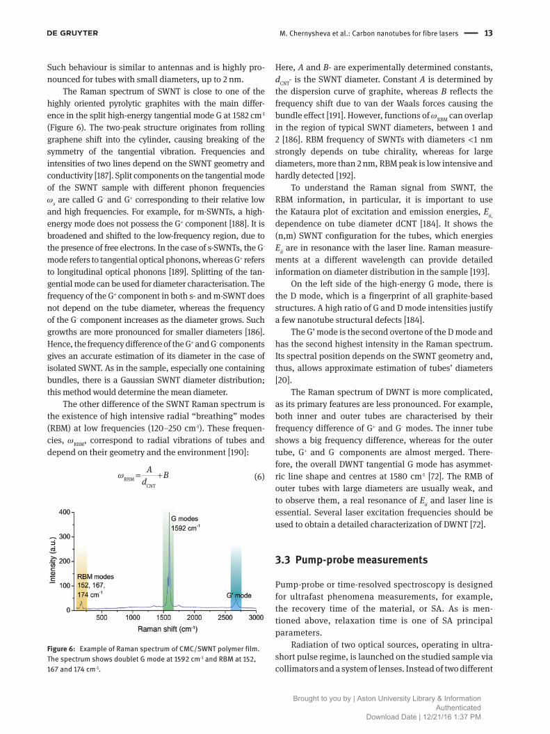
The Raman spectrum of SWNT is close to one of the highly oriented pyrolytic graphites with the main differ-ence in the split high-energy tangential mode G at 1582 cm-1 (Figure 6). The two-peak structure originates from rolling graphene shift into the cylinder, causing breaking of the symmetry of the tangential vibration. Frequencies and intensities of two lines depend on the SWNT geometry and conductivity [187]. Split components on the tangential mode of the SWNT sample with different phonon frequencies ωs are called G- and G+ corresponding to their relative low and high frequencies. For example, for m-SWNTs, a high-energy mode does not possess the G+ component [188]. It is broadened and shifted to the low-frequency region, due to the presence of free electrons. In the case of s-SWNTs, the G- mode refers to tangential optical phonons, whereas G+ refers to longitudinal optical phonons [189]. Splitting of the tan-gential mode can be used for diameter characterisation. The frequency of the G+ component in both s- and m-SWNT does not depend on the tube diameter, whereas the frequency of the G- component increases as the diameter grows. Such growths are more pronounced for smaller diameters [186]. Hence, the frequency difference of the G+ and G- components gives an accurate estimation of its diameter in the case of isolated SWNT. As in the sample, especially one containing bundles, there is a Gaussian SWNT diameter distribution; this method would determine the mean diameter.
The other difference of the SWNT Raman spectrum is the existence of high intensive radial “breathing” modes (RBM) at low frequencies (120–250 cm-1). These frequen-cies, ωRBM, correspond to radial vibrations of tubes and depend on their geometry and the environment [190]:
RBM
CNT
A Bd
ω = +
(6)
Figure 6: Example of Raman spectrum of CMC/SWNT polymer film. The spectrum shows doublet G mode at 1592 cm-1 and RBM at 152, 167 and 174 cm-1.
Here, A and B- are experimentally determined constants, dCNT- is the SWNT diameter. Constant A is determined by the dispersion curve of graphite, whereas B reflects the frequency shift due to van der Waals forces causing the bundle effect [191]. However, functions of ωRBM can overlap in the region of typical SWNT diameters, between 1 and 2 [186]. RBM frequency of SWNTs with diameters < 1 nm strongly depends on tube chirality, whereas for large diameters, more than 2 nm, RBM peak is low intensive and hardly detected [192].
To understand the Raman signal from SWNT, the RBM information, in particular, it is important to use the Kataura plot of excitation and emission energies, Eii, dependence on tube diameter dCNT [184]. It shows the (n,m) SWNT configuration for the tubes, which energies Eii are in resonance with the laser line. Raman measure-ments at a different wavelength can provide detailed information on diameter distribution in the sample [193].
On the left side of the high-energy G mode, there is the D mode, which is a fingerprint of all graphite-based structures. A high ratio of G and D mode intensities justify a few nanotube structural defects [184].
The G’ mode is the second overtone of the D mode and has the second highest intensity in the Raman spectrum. Its spectral position depends on the SWNT geometry and, thus, allows approximate estimation of tubes’ diameters [20].
The Raman spectrum of DWNT is more complicated, as its primary features are less pronounced. For example, both inner and outer tubes are characterised by their frequency difference of G+ and G- modes. The inner tube shows a big frequency difference, whereas for the outer tube, G+ and G- components are almost merged. There-fore, the overall DWNT tangential G mode has asymmet-ric line shape and centres at 1580 cm-1 [72]. The RMB of outer tubes with large diameters are usually weak, and to observe them, a real resonance of Eii and laser line is essential. Several laser excitation frequencies should be used to obtain a detailed characterization of DWNT [72].
3.3 Pump-probe measurements
Pump-probe or time-resolved spectroscopy is designed for ultrafast phenomena measurements, for example, the recovery time of the material, or SA. As is men-tioned above, relaxation time is one of SA principal parameters.
Radiation of two optical sources, operating in ultra-short pulse regime, is launched on the studied sample via collimators and a system of lenses. Instead of two different
Brought to you by | Aston University Library & InformationAuthenticated
Download Date | 12/21/16 1:37 PM

14 M. Chernysheva et al.: Carbon nanotubes for fibre lasers
pulsed laser sources, one pulse train can be divided into two parts using a beam splitter. However, there is no par-ticular need to use sources generating at one wavelength. In this case, pump-probe spectroscopy would be referred as a two-colour measurement, although the pulse dura-tion plays a critical role as to determining the measure-ment resolution. The pulse from the pump source arrives first on the sample. The photon energy matches the E22 energy transition of CNT. As a result of the excitation, the electron (e-) and hole (h+) originate in the second conduc-tion c2 and valence v2 bands, correspondingly, and form a strongly bound exciton (Figure 3) [194]. Following that, the exciton relaxes the intraband to the fundamental band gap E11 with the origination of one or two excitons of the first sub-band or unbound electron-hole pairs [195]. After the adjusted delay, the probe pulse of weaker power is launched to measure the sample’s transmission as a function of delay time. Pump-probe measurements provide information on the decay of the generated exci-tation and, thus, allows estimate recovery time of CNT samples.
For CNTs as typical semiconductors, the transmission bi-temporal response is inherent. Intraband and interband relaxation responses can explain the existence of fast and slow recovery time components (Figure 7) [197].
3.4 Power-dependent characterisation
Along with all of above-described techniques, power-dependent measurements are essential for CNT sample characterisation as SA. Power-dependent measurements allow to determine the nonlinear optical absorption of
1.0
0.8
0.6
0.4∆T/T
(no
rm)
τmin=370 fs
λprobe=2 µm
Ppump=55 mW
Ppump=10 mW
Ppump=2.5 mW
0.2
0.0-800 0 800 1600
Pump probe delay (fs)
Figure 7: Typical plot of transmission as a function on adjustable time delay [196].
1.35 2.6 mW1.44 mW0.88 mW0.43 mW0.23 mW0.15 mW
0.026 mW
1.30
1.25
1.20
1.15
1.10
Nor
mal
ized
tran
smitt
ance
1.05
0.95-1000 -500 500
Z (µm)
10000
1.00
Figure 8: Typical transmission as function of displacement in open aperture Z-scan measurements [169].
the sample and estimate modulation depth, which are relevant parameters of SA. This can be done by two main methods, the so-called Z- and P-scan [198].
During Z-scan measurements, ultrashort optical pulses with Gaussian beam profiles are launched on the sample. Slowly moving the sample on the translation stage along the optical axis of the beam, the intensity of the launched light I0 is altered, according to equation (7), passing through the maximum on the focal point:
pulse20
(0)E
Iπω τ
=
(7)
Here, ω0- is the radius of the beam waist, Epulse- is the pulse energy and τ- is the pulse duration. Further, the beam is refocused by a lens onto a photodiode to measure the output power and, hence, sample transmission. In the case of incident power increase, the absorption saturates, and nonlinear bleaching effect can be observed. This method is called “open aperture” Z-scan [199].
Figure 8 shows the normalised transmission ΔT as a function of the sample position Z, which can be described by the equation (z-position):
02
20
1( )2 2 1
T ZZZ
α∆ =
+
(8)
Here, Z0- is the Rayleigh range, Z0 = 2nωπω0/λ, α0 = βI0 (1-e-aL)/α, α- is the absorption coefficient, β- is the two-photon absorption coefficient and L- is the sample length.
The other approach is the so-called closed aperture Z-scan measurement with aperture placed in the far field, i.e. between the sample and the photodiode so
Brought to you by | Aston University Library & InformationAuthenticated
Download Date | 12/21/16 1:37 PM

M. Chernysheva et al.: Carbon nanotubes for fibre lasers 15
that the distance from the lens focus is much larger than Z0. The aperture can lock in to half of the beam inten-sity, transmitted through the sample [200]. Owing to nonlinear properties of the sample, the intensity of the light incident on the photodetector will vary due to self-focusing or defocusing in the sample, as in Kerr lenses [199]. The output of the photodetector during the sample translation will show the peak and valley, which posi-tion depends on the sign of the nonlinear shift in the sample [201]. The phase shift occurring in the sample Δφ can be estimated with the change of the normalised transmittance between the peak and valley ΔT if the fraction of the light transmitted through the aperture S is known [200]:
0.270.406(1- )
TS
∆∆φ=
(9)
However, if the sample possesses not only a nonlinear refractive index but nonlinear absorption as in the case of CNT, the “close aperture” Z-scan method becomes inaccu-rate, and the function of the nonlinear refraction becomes asymmetrical. Hence, the result of the closed aperture measurement should be divided by the open aperture scan to restore the symmetry of the curves [202].
Another technique to realise the power-depend-ent transmission is to alter directly the intensity of the light incident on the sample, using the so-called P-scan method (see Figure 9). The launched power of the mode-locked laser source generating sub-picosecond pulses is varied with means of the variable optical attenuator (VOA) so that the laser output characteristics are strictly fixed. The radiation from the ultrafast laser is split equally and launched both into the reference arm and on the SWNT sample. The output power is measured simultaneously from both ports by the power meter.
Figure 9: Modulation depth measurement setup. Inset: Normalised absorption and transmission as a function of pump power.
The transmission at the sample as a function of the launched intensity is presented in the inset in Figure 9 and can be analysed using the Beer-Lambert law [203]:
0 0-( )exp ns I LT α α+= (10)
The absorption decreases with the peak power increase according to the equation [11]:
0peak
peak
peaksat
1nsP
PP
αα= +
+
(11)
Here, α0- is the absorption modulation depth, αns- is the non-saturable absorption, Ppeaksat- is the saturation peak power.
In summary, the P-scan offers an easy and effec-tive method to observe the saturation of absorption and measure the modulation depth of samples to character-ise nonlinear absorption behaviour. It benefits from the insensibility to sample non-uniformity and, therefore, is a successful technique for CNT sample characterisation.
3.5 Photoluminescence excitation
The first infrared photoluminescence of carbon nano-tubes dispersed in a solution was demonstrated in 2002 [164, 183] proving emission from electron-hole recombina-tion at the band edge. The characterisation became pos-sible only after individually isolated carbon nanotubes could be obtained. Nanotube isolation is critical due to the presence of both m- and s-CNTs in the solution and the tendency to form bundles, which causes radiation-less intertube carrier transfer [204]. Photoluminescence excitation (PLE) allows not only to verify the presence of single-walled carbon nanotubes in a sample but also to determine the geometry of s-CNTs with a high accuracy, study their electronic and optical properties, interac-tions of single nanotubes in bundles [49] and with the environment [205].
In photoluminescence excitation (PLE), a sample is scanned over a broad range of excitation and emission wavelengths to create a PLE map. The absorption occurs on E22, E33, … transitions, while emission is only on E11. As the absorption and emission energies strongly depend on the chirality, every CNT has a specific combination of allowed energy transfers as a fingerprint. The typical PLE map is presented in Figure 10. It allows to deter-mine energy transfers and, hence, identify the geometry of nanotubes in the solution [206]. CNT bundles show
Brought to you by | Aston University Library & InformationAuthenticated
Download Date | 12/21/16 1:37 PM

16 M. Chernysheva et al.: Carbon nanotubes for fibre lasers
complex PLE spectrum involving EET between tubes. In [47] it is shown that radiationless relaxation enhances PLE of acceptor tubes. This can be beneficial as it surpasses the poor performance of individual CNTs.
Along with basic exciton energy transfer (EET) E11, E22, E33, …, the PLE map shows less intensive transfers. At excitation energies of higher than 200 meV and < 130 meV, there are spectral components, corresponding to the EET of phonons [207].
4 CNT-based SA implementation
4.1 Nanocomposites
Since the first demonstration in 2003 of CNT application as a SA in mode-locked fibre lasers, numerous laser con-figurations and methods for CNT incorporation have been demonstrated. The pioneering research was focused on the application of mirrors and fibre ferrules with a sprayed solution of CNTs [208] or by direct growth of the CNT in a substrate [209]. However, the most straightforward method is utilisation of CNT-polymer films sandwiched between fibre ferrule connectors or fibre ends [51, 69, 210].
This technique previously was regarded to have low thermal damage threshold, as the most intensive central part of the optical field effectively interacts with the SA. With the microscopy, the sample degradation spot can be easily observed (Figure 11) [129]. The diameter of the
Figure 10: Example of photoluminescence map of the SWNT- polymer solution. The map clearly shows the presence of SWNT with geometries: (6,5); (7,3); (7,5); (7,6); (8,3); (8,4); (8,7); (9,2); (9,4); (10,3).
Figure 11: Microscopic pictures of the PVA film after a 24-h high-power operation.
degradation spot is comparable with the effective mode field diameter of the optical fibre. However, several recent works show the high potential of such SA for high-power operation [71, 129].
Polymer nanocomposites allow alignment of SWNTs by their stretching [182] or fabricating with the Langmuir-Blodgett technique [212] due to the high anisotropic inter-action of SWNTs with light. In aligned SWNTs, absorption reaches the maximum when launched light is polarised par-allel to the alignment direction, increasing, therefore, the saturable absorption without raising non-saturable losses.
4.2 Microfluidic devices
Femtosecond laser micromachined in-fibre microfluidic devices are an ideal platform for accommodating a nanopar-ticle dispersion solvent [180, 211, 213]. This in-fibre micro-chamber device is fabricated by femtosecond laser tightly focused irradiation followed by selected chemical etching of laser-modified areas. A typical microscopic picture of this microchamber is shown in Figure 12 [211]. The fabricated in-fibre microfluidic device was filled with CNT dissolved in n-methyl-2-pryrrolidone (NMP) solvent. The solvent with a high boiling point allows a stable dispersion of CNTs at small concentrations even with no surfactants and polymers. The ring EDFL mode locked with a microfluidic canal generates 3.37 ps of soliton pulses at a fundamental repetition rate of
Brought to you by | Aston University Library & InformationAuthenticated
Download Date | 12/21/16 1:37 PM

M. Chernysheva et al.: Carbon nanotubes for fibre lasers 17
2.3 MHz with the average output power of 29 mW [211]. The mode-locked fibre laser with SWNT NMP dispersion showed a high stability while operating for more than 24 h in labora-tory conditions. However, the evaporation of NMP and mois-ture adsorption can affect the thermodynamic equilibrium in the solvent, resulting in CNT aggregation and significant scattering loss [211].
4.3 Optical deposition
The novel technique, based on the optical tweezer effect to deposit CNTs selectively onto only a core region of an optical fibre end, was demonstrated for the first time in 2007 [214]. The main advantage of the optically driven deposition method is its reliability, repeatable accuracy, easy implementation and possibility of process automa-tion. The optical trapping occurs due to the interaction of the intensity gradient of the laser beam and the dipole moment of the CNT composite (Figure 13). The laser energy heats the solution locally and, thus, creates the thermally driven convection flow [215]. Moreover, forces of electro-magnetic field pressure act along the laser beam. The dif-ference between temperatures of the heated liquid and the cold fibre surface causes the thermodiffusion, which results in CNT flow along the temperature gradient [215].
During the optical deposition, the laser radiation is divided into two parts, one of which is measured for the reference by a power meter. The other one is injected into a polymer solution with dispersed CNTs [214]. The power of the reflected light from the fibre end was measured by another power meter through a circulator. The optical reflectometry offers the capability to detect the start-ing time of CNT deposition and, therefore, to control the number of the deposited CNTs. Besides, the reflectometry
Figure 12: Microscopic pictures of the femtosecond laser fabricated microfluidic chamber devices. Adapted from [211].
Figure 13: Theoretical explanation of CNT optical deposition process on fibre edge.
assists preferential deposition as the solution condition and the sizes of the bundles change in time [214].
To enhance the thermal damage threshold, CNTs were suggested to deposit on the fibre connector end in a ring pattern for an evanescent-field interaction instead of direct interaction [216]. The ring pattern is believed to be a result of the balance between the scattering and gradi-ent forces as well as circularly symmetric radiation field distribution.
4.4 Evanescent field interaction
Problems arising from ageing or radiation damage of poly-meric matrices used in CNT-polymer nanocomposites are driving efforts to develop other methods of interaction between fibre laser radiation and CNT, for example, the interaction of the evanescent field of the light propagating in the fibre with CNT-SA.
One such method is the introduction into the laser resonator of a D-shaped fibre that has a side-polished surface, onto which CNTs are deposited. This approach requires a fine-polished surface for the CNT deposition. A CNT-deposited D-shaped fibre was used to mode lock an Er-doped fibre laser with output pulse duration of 470 fs [209]. These CNT-deposited D-shaped fibres can be also applied to implement widely tuneable wavelength con-verters, based on cross-phase modulation-induced non-linear polarisation rotation in a CNT-deposited D-shaped fibre [217].
Brought to you by | Aston University Library & InformationAuthenticated
Download Date | 12/21/16 1:37 PM

18 M. Chernysheva et al.: Carbon nanotubes for fibre lasers
Tapered fibres (or micro-fibres) may also produce an interaction of CNT with the evanescent field of the guided light in the fibre [50, 218, 219]. In this case, CNTs are depos-ited around the tapered section of the fibre, or the tapered part of the fibre is placed into a CNT-polymer compos-ite when the polymer is in a liquid phase. CNT-deposited tapered fibres also may be used for wavelength conversion of generated pulses [220]. Main drawback of tapered fibres is their relatively low mechanical strength. To squeeze the eva-nescent field of the guided light to the surface of the fibre, its diameters should be of only several micrometres.
The same method of evanescent field interaction is uti-lised in SA based on photonic crystal or hollow optical fibre filled with carbon nanotube dispersion [67]. An aqueous sus-pension of individual SWNTs filled the fibre under a gas pres-sure about 10 atm (Figure 14). After this, the fibre should be kept a few days at 30°C for water evaporation. In the result, in thin SWNT, films dry and deposit on fibre walls [221].
5 Fibre lasers with CNT-based SA
5.1 Ytterbium (Yb)-doped fibre lasers
Mode-locked operation of a Yb-doped fibre laser with CNT-based SA was for the first time demonstrated in 2005 [222]. The Yb-doped fibre laser produced 180-fs-long solitons at a repetition rate of 23.3 MHz. This laser had a transmission-type SA incorporating CNTs with saturable absorption depth of 4%. Later on, the possibility of mode locking in
Figure 14: Technology of hollow core fibre filling with CNTs.
a Yb-doped fibre laser with CNT in an all-fibre configura-tion, using a tapered fibre, embedded in a composite CNT-polymer, was demonstrated [50]. The normal dispersion laser cavity provided generation of 1.5-ps chirped pulses, which could be compressed down to 250 fs outside the cavity [50]. In Kelleher et al. [223], the possibility of pulse duration adjustment was demonstrated within the range from 20 ps to 2 ns at repetition rates between 21 MHz and 177 kHz. Mode-locked operation in Yb-doped fibre lasers was also demonstrated using DWNT-SA [72].
In many implementations, CNT-based mode locking is accompanied by the effect of NPE, whose presence may be either beneficial (an additional SA) or detrimental (NPE causes instability in mode-locked operation). In [224] Kobtsev et al. reported stable mode locking in a laser with a cavity mostly made of a PM fibre. The laser delivered stable mode-locked operations over several hours or days, and self-started reliably after the off-on cycling without additional tuning. Improvement of mode-locking stability by adopting PM configurations was confirmed in [225].
The possibility of wavelength tuning in Yb-doped fibre lasers mode locked by CNT was demonstrated in [51, 226]. In [226] Li et al. reported spectral tuning of output pulses in the range of 1025–1037 nm, achieved through the adjustment of the pumping radiation power, whereas in [51] Fedotov et al. investigated the impact of the bire-fringent fibre Lyot filter and achieved wavelength tuning within 1060–1066 nm of fibre filter. Figure 15A shows the schematic diagram of the Yb ring laser with a Lyot filter. The SA was represented by a polymer film with prepared CoMoCATs SWNT, dispersed in 25 ml of water with 20 mg of sodium dodecylbenzene sulfonate (SDBS) surfactant and mixed with a PVA polymer. Utilisation of a fibre Lyot filter enables the variation of the laser output spectrum width within the 0.15–1.25 nm range and detuning the central wavelength by up to 5 nm.
CNT-based SA may be used in Yb-doped fibre lasers both for mode locking and for Q-switching [227], and these two types of laser operation may be even supported by the same laser device at a different pumping power [51, 228].
As was shown in [229], CNT may be used in fibre lasers not only as mode lockers but also as polarisation control-lers, owing to anisotropic properties of CNT.
5.2 Er-doped fibre lasers
The first report of CNT used for passive laser mode locking was presented in 2003 [208], and the first journal publica-tions going into details of this work appeared a year later [208]. In [208, 229], both linear and ring Er-doped fibre
Brought to you by | Aston University Library & InformationAuthenticated
Download Date | 12/21/16 1:37 PM

M. Chernysheva et al.: Carbon nanotubes for fibre lasers 19
lasers were studied, in which mode locking was achieved by SWNT sandwiched between two optical plates. Up to the present time, CNT mode-locked Er-doped fibre lasers have been widely explored. The shortest pulse duration generated, to date, in CNT mode-locked Er-doped fibre lasers is 66-fs long [230], while the longest one is 332-ns long [231]. The broad bandwidth of CNT allows spectral tuning in the range from 1532 to 1562 nm [232] and multi-wavelength generation [233].
CNT mode-locked Er-doped fibre lasers exhibit har-monic mode locking by sustaining stable operation at the 10th [210] or even 23rd [234] harmonic of the fundamental repetition frequency. The laser setup presented in [210] constitutes 80 cm of highly doped erbium fibre, the PVA/SWNT-SA sandwiched between fibre ferrules (Figure 16). The laser supported a maximum of 10 harmonic orders at a pump power of 141 mW showing a repetition rate of 245 MHz. The SMSR for all harmonic orders is between
Figure 15: Yb-doped fibre laser setup. YDF, Ytterbium-doped fibre; IWDM, isolating wavelength division multiplexor; PC, polarization con-troller; PM, polarisation-maintaining fibre. Inset: Central wavelength tuning. Adapted from [51].
Figure 16: Schematic configuration of the harmonic mode-locked Er-doped fibre laser. EDF, Erbium-doped fibre; WDM, wavelength division multiplexor; PC, polarisation controller; OIS, isolator. Inset: RF spectrum of 10th harmonics at 245 MHz. Adapted from [210].
Brought to you by | Aston University Library & InformationAuthenticated
Download Date | 12/21/16 1:37 PM

20 M. Chernysheva et al.: Carbon nanotubes for fibre lasers
39 dB. The measured timing jitter at 221 MHz, the 10th harmonic order was approximately 4.8 ps.
The polarisation dynamics in a mode-locked fibre laser system has rarely been explored [128, 235, 236]. In [235] Mou et al. proposed and demonstrated a SWNT/PVA thin-film mode-locked EDFL generating polarisation-locked vector soliton pulses with 583 fs temporal width and an output power of 3 mW (pulse energy of 118 pJ). A commercially available polarimeter with 1-μs resolution and a measure-ment interval of 1 ms was used to observe the exact state of polarisation (SOP) in the Poincare sphere. The first com-prehensive experimental analysis of new families of vector solitons in a CNT mode-locked fibre laser with anomalous dispersion laser cavity was presented [236]. By tuning an in-cavity polarisation controller, a new type of vector soli-tons with locked and precessing states of polarisation for fundamental soliton and multipulsing operations on a time scale of 40–40,000 roundtrips have been achieved. In [128], the authors presented the first experimental results on the state of polarisation evolution of tightly and inter-leaved bound states generated in EDFL with fixed delay and phase differences of π/2 and π.
Er-doped fibre lasers with CNT can also be passively Q-switched, providing a comparatively high level of output pulse energy (up to 531 nJ) [237] at shorter pulse durations of 662 ns [238].
5.3 Bismuth (Bi)-doped fibre lasers
Various applications in broadband data transmis-sion, medical applications and for high-brightness
frequency-doubled visible sources have drawn the research interest to the extension of fibre laser emis-sion band to 1100–1550 nm. In contrast with rare earth-doped active fibres, which cannot provide generation at this band, Bi-doped fibres have shown the broad gain in the region, favourable for ultrashort pulse formation. Despite such high demand in laser sources, there are just several works on mode-locked Bi-doped fibre lasers, uti-lising SESAM [239, 240] and CNT-based SA [61]. The first Bi-doped fibre laser to produce stable ultrashort pulses by using the SWNT-based SA was proposed and realised in 2010 [61]. Here, the generation was achieved in both all-normal dispersion (ANDi) and dispersion-managed (DM) net anomalous cavity at 1157 and 1177 nm band, correspondingly. The ANDi laser generated 558 ps pulses having the energy of 1.4 nJ, whereas the DM cavity oper-ated in the average-soliton regime with a 4.7-ps duration and the energy of ~3 pJ.
Further works aimed to broaden the generation to the telecommunication L-band. For this, Bi-Er co-doped optical fibres were used as an active gain [60]. In this work Ahmad et al. suggested the application of the dual-pumping configuration at 980 and 1480 nm to achieve amplified spontaneous emission spectrum with a band-width of more than 100 nm, from 1520 to 1625 nm. As a result, the ring fibre laser mode locked with commer-cially available CNTs generates 460-fs pulses with 5 mW of average power.
The most recent work of Nepponen et al. is focused on the development of a 1.44-μm all-bismuth fibre master oscillator-power amplifier (MOPA) system (Figure 17) [62]. The authors used butt-coupled SWNT-based SA deposited
Figure 17: Setup for Bi-doped fibre MOPA. BiDF, Bismuth-doped fibre; WDM, wavelength division multiplexor; PC, polarisation controller; ISO, isolator. Inset: Autocorrelation traces before and after the compression in bismuth fibre amplifire. Adapted from [62].
Brought to you by | Aston University Library & InformationAuthenticated
Download Date | 12/21/16 1:37 PM

M. Chernysheva et al.: Carbon nanotubes for fibre lasers 21
Figure 18: Configuration of the SWNT mode-locked Tm-doped fibre laser in (A) geometry, based on NALM; (B) ring configuration with NPE. TDF, Thulium-doped fibre; WDM, wavelength division multiplexor; PC, polarisation controller; GeO2/SiO2, germanium-silicate fibre; (PD)-ISO, (polarization-dependent) isolator. Inset: Output pulse characteristics. Adapted from [242].
onto a silver mirror to support the mode-locked operation. After amplification and compression, the laser generates 240-fs pulses with 3.1-kW peak power.
5.4 Thulium (Tm)-doped fibre lasers
The increasing demand for low-cost highly stable ultrafast laser generation at the mid-IR spectral region, and at par-ticular, ~2 μm, has stimulated a significant research effort into the development of the Tm-doped fibre lasers. The pioneer works on Tm-doped fibre lasers mode locked with SWNTs used ferrule-type SA [69], or fibre tapers embed-ded in an SWNT/polymer composite [63]. Here, we would like to pay more attention to the other approach, allowing high-quality ultrashort pulse formation. This technique utilises two SAs in the cavity [241]: slow, SWNT, and fast, NPE or NALM, with relaxation times of 300–600 fs and 5 fs, correspondingly.
In [70] first introduced this technique to Tm-doped fibre lasers (Figure 18A). The NALM is formed by a 20:80 fibre coupler and dispersion managed by normal disper-sion germanium-silica fibre (GeO2/SiO2) [239]. A polymer film based on carboxymethylcellulose (CMC) with dis-persed arc discharge SWNTs [243] is fixed between two angle-polished optical ferrules. The shortest pulse dura-tion of 450 fs at 1870 nm central wavelength band (insert in Figure 18A) has been achieved when the total was zero NALM dispersion. The maximum average output power could be scaled from 6.3 to 18 mW, corresponding to the laser peak power of 625 W and pulse energy of 0.4 nJ.
The development of high-power lasers, without application of the complicated MOPA schemes, is very attractive, though technically challenging. Chernysheva et al. [71] present the high-power thulium-doped fibre ring laser with the variable pulse repetition rate between 6.4 and 72.5 MHz and tuneable from 1.86 to 1.98 μm (Figure 18B). The laser was mode locked by laser ablation
Brought to you by | Aston University Library & InformationAuthenticated
Download Date | 12/21/16 1:37 PM

22 M. Chernysheva et al.: Carbon nanotubes for fibre lasers
PVA/SWNT-SA [244]. At the repetition rate of 72.5 MHz, the laser slope efficiency reached 32.6%. The laser gener-ated 1.2 ps and 600 fs solitons with the average output power of 300 mW, giving the pulse energy of 2.93 nJ. Inset in Figure 18B demonstrates the excellent long-term sta-bility of the laser operation at 300 mW output power for 10 h under the laboratory conditions. The mode locking could be self-started reliably after the off-on cycling. This also proves the high thermal stability of the PVA/SWNT sample, which could endure an optical fluence of 3.46 mJ/cm2 without demonstration of the significant degra-dation of laser operation. The laser setup with the cavity length of 21 m after compression generates 500-fs pulses with the average output power of 117 mW, corresponding to the pulse energy of 10.87 nJ and peak power of 21.7 kW [71].
The same laser setup has been studied through the intracavity dispersion variation in the range between +0.194 and -0.068 ps2 [245]. The interesting feature was observed at high normal intracavity dispersion, +0.19 ps2. The spectrum possessed strong side-bands, which can be referred to four-wave mixing.
5.5 Holmium (Ho)-doped fibre lasers
Although there are numerous applications of lasers gen-erating ultrashort pulses beyond the 2-μm band, the main research interest has been attracted by thulium-doped fibre lasers, rather than Ho- or Tm:Ho-doped ones. Only a few works were focused on Ho-doped ultrafast lasers, utilising gain switching [219], fibre-based SA [246] and
quantum dot-doped glass absorbers [247]. In 2009, the new approach of Tm:Ho-doped fibre application has been demonstrated [63]. The authors used a SA based on a fibre taper embedded in an SWNT/polymer composite. The laser generates transform-limited 750-fs soliton pulses with 0.5-nJ energy at the wavelength of ~1.9 μm [63].
A more recent paper studying Tm:Ho co-doped fibre laser utilises the other technique of SWNT-based SA imple-mentation, i.e. mirror coating [64]. The polymer-free CNT layer on a highly reflective Ag mirror enabled the build-ing of a robust and compact linear cavity laser. The setup features significantly improved output characteristics of output power, stability and absorber damage threshold. The all-fibre laser delivered ~1.0-ps pulses with 15-mW average output power at the central wavelength of 1991 nm. Moreover, the authors demonstrated the ultra-broad-band performance of the SWNT-based SA by achievement of ultrashort pulse generation in similar Yb- and Er-doped fibre lasers.
An analogous approach has been demonstrated in [65], though the cavity comprised of pure Ho-doped fibre. The shortest achieved pulse duration was 890 fs at 2085 nm, with an average output power of 45 mW. The wide gain spectrum of Ho-doped fibres and broadband absorp-tion of CNT allow to achieve tuneable pulsed operation. By adjustment of the polarisation controller and scan-ning the modal spot over the CNT reflector, optical pulse spectra could be tuned in the range of 2030–2100 nm (Figure 19). The other method to realise the wide spectral tenability involved the intentional variation of CNT film thickness across the sample, resulting in a spectral shift of CNT absorption [65].
Figure 19: Schematic configuration of the Ho-doped fibre laser. HDF, Holmium-doped fibre; PC, polarisation controller. Inset: Tunability of the mode-locked Ho-doped fibre laser. Adapted from [65].
Brought to you by | Aston University Library & InformationAuthenticated
Download Date | 12/21/16 1:37 PM

M. Chernysheva et al.: Carbon nanotubes for fibre lasers 23
6 ConclusionWe have reviewed the current state-of-the-art in CNT fabri-cation, technologies and ultrafast photonic applications. The important SWNT-polymer composite application is as SAs in fibre lasers for ultrashort pulse generation through the passive mode locking. SWNT-polymer composites offer a broad operation and tunability range, as well as advan-tages in fabrication and integration into the laser cavity.
Enrichment of SWNT-SAs by the selection accord-ing to their diameter and conductivity type holds great promise for further device optimisation as their present performance is limited by the redundant, off-resonance and m-tubes, tailored bundles of m-SWNTs and s-SWNTs as well as by host polymers.
CNT photonics is still at the initial stage of its develop-ment. A variety of other promising SWNT-based photonic devices can be implemented, for example, birefringence filters, polarisation rotating devices, dispersion compen-sators, pulse compressors, regenerators and many others. Moreover, other types of the lasers, but fibre, mode locked by CNT-SA, can potentially enable further technological enhancements. For example, integration of CNT directly into the dot laser cavity helps towards high repetition rates in quantum-dot lasers. SWNT can serve as an SA in verti-cal-cavity surface emitting lasers (VECSEL), microdisc and slab lasers. CNT-based photonics offers new opportunities for engineering innovations and developing new photonic techniques for various emerging applications, leading to new breakthroughs in science and technology.
Acknowledgements: The support by the Marie-Curie Inter-national Research Staff Exchange Scheme “TelaSens” project, Research Executive Agency Grant No. 269271, Pro-gramme: FP7-PEOPLE-2010-IRSES and European Research Council through the FP7-IDEAS-ERC grant ULTRALASER are gratefully acknowledged. The authors also would like to acknowledge the support of the Grant of Ministry of Education and Science of the Russian Federation (agree-ment no. 14.B25.31.0003), the Young Eastern Scholar program (QD2015027) at Shanghai Institutions of Higher Learning, and Human Capacity Development Program of Ministry of Higher Education and Scientific Research of Iraq-Kurdistan Region.
References[1] Midwinter JE. Photonics in switching: the next 25 years of optical
communications? IEE Proc J Optoelectron 1992;139:1–12.
[2] Cui M, Zeitouny MG, Bhattacharya N, van den Berg SA, Urbach HP, Braat JJM. High-accuracy long-distance measurements in air with a frequency comb laser. Opt Lett 2009;34:1982.
[3] Mukamel S. Multidimensional femtosecond correlation spec-troscopies of electronic and vibrational excitations. Ann Rev Phys Chem 2000;51:691–729.
[4] Steinmetz T, Wilken T, Araujo-Hauck C, Holzwarth R, Hansch TW, Pasquini L, Manescau A, D’Odorico S, Murphy MT, Kentischer T, Schmidt W, Udem T. Laser frequency combs for astronomical observations. Science 2008;321:1335–7.
[5] Keller U. Recent developments in compact ultrafast lasers. Nature 2003;424:831–8.
[6] Duling IN III. Compact sources of ultrashort pulses, volume 23, Cambridge University Press, 2006. https://books.google.com/books?id=oYGvoIKYkD8C&pgis=1.
[7] Fermann ME, Galvanauskas A, Sucha G, ed. Ultrafast Lasers: technology and applications. CRC Press, 2002. https://books.google.com/books?hl=en&lr=&id=i8NvQbG5t_8C&pgis=1.
[8] Garmire E. Resonant optical nonlinearities in semiconductors. IEEE J Sel Top Quantum Electron 2000;6:1094–110.
[9] Haus H. Mode-locking of lasers. IEEE J Sel Top Quantum Elec-tron 2000;6:1173–85.
[10] Agrawal GP. Nonlinear fiber optics, optics and p hotonics. Academic Press, 2007. http://www.springerlink.com/index/q022707lwv86154v.pdf.
[11] Silfvast WT. Laser fundamentals. 1997.[12] Haus HA. Theory of mode locking with a fast saturable
absorber. J Appl Physics 1975;46:3049.[13] Haus H. Theory of mode locking with a slow saturable
absorber. IEEE J Quantum Electron 1975;11:736–46.[14] Martinez OE, Fork RL, Gordon JP. Theory of passively mode-
locked lasers including self-phase modulation and group-velocity dispersion. Opt Lett 1984;9:156.
[15] Haus H. Parameter ranges for CW passive mode locking. IEEE J Quantum Electron 1976;12:169–76.
[16] Ippen EP. Principles of passive mode locking. Appl Phys B Laser Opt 1994;58:159–70.
[17] Kryukov P, Letokhov V. Fluctuation mechanism of ultrashort pulse generation by laser with saturable absorber. IEEE J Quan-tum Electron 1972;8:766–82.
[18] Glenn W. The fluctuation model of a passively mode-locked laser. IEEE J Quantum Electron 1975;11:8–17.
[19] Mocker HW, Collins RJ. Mode competition and self-locking effects in a Q-swithed ruby laser. Appl Phys Lett 1965;7:270.
[20] Reich S, Thomsen C, Maultzsch J. Carbon nanotubes: basic concepts and physical properties, volume 10, 2004.
[21] Snitzer E. Optical maser action of Nd+3 in a barium crown glass. Phys Rev Lett 1961;7:444–6.
[22] Lariontsev EG, Serkin VN. Possibility of using self-focusing for increasing contrast and narrowing of ultrashort light pulses. Sov J Quantum Electron 1975;5:796–800.
[23] Svelto O. Principles of lasers. USA, Springer, 2010.[24] Keller U. Ultrafast solid-state lasers. Prog Opt 2004;46:1–115.[25] Doran NJ, Wood D. Nonlinear-optical loop mirror. Opt Lett
1988;13:56.[26] Fermann ME, Haberl F, Hofer M, Hochreiter H. Nonlinear
amplifying loop mirror. Opt Lett 1990;15:752.[27] Isomaki A, Vainionpaa A-M, Lyytikainen J, Okhotnikov O. Semi-
conductor mirror for optical noise suppression and dynamic dis-persion compensation. IEEE J Quantum Electron 2003;39:1481–5.
Brought to you by | Aston University Library & InformationAuthenticated
Download Date | 12/21/16 1:37 PM

24 M. Chernysheva et al.: Carbon nanotubes for fibre lasers
[28] Okhotnikov O, Grudinin A, Pessa M. Ultra-fast fibre laser systems based on SESAM technology: new horizons and applications. New J Phys 2004;6:177.
[29] Liverini V, Schön S, Grange R, Haiml M, Zeller SC, Keller U. Low-loss GaInNAs saturable absorber mode locking a 1.3-μm solid-state laser. Appl Phys Lett 2004;84:4002–4.
[30] Wilson J, Yoffe A. The transition metal dichalcogenides discussion and interpretation of the observed optical, electrical and structural properties. Adv Phys 1969;18:193–335.
[31] Hsieh D, Qian D, Wray L, Xia Y, Hor YS, Cava RJ, Hasan MZ. A topological dirac insulator in a quantum spin hall phase. Nature 2008;452:970–4.
[32] Bernard F, Zhang H, Gorza S-P, Emplit P. Towards mode-locked fiber laser using topological insulators. In: Advanced photonics congress. OSA, NTh1A.5:Washington, DC, 2012.
[33] Zhao C, Zhang H, Qi X, Chen Y, Wang Z, Wen S, Tang D. Ultra-short pulse generation by a topological insulator based satura-ble absorber. Appl Phys Lett 2012;101:211106.
[34] Lu S, Zhao C, Zou Y, Chen S, Chen Y, Li Y, Zhang H, Wen S, Tang D. Third order nonlinear optical property of Bi2Se3. Opt Express 2013;21:2072–82.
[35] Hasan T, Sun Z, Wang F, Bonaccorso F, Tan PH, Rozhin AG, Ferrari AC. Nanotube-polymer composites for ultrafast photonics. Adv Mater 2009;21:3874–99.
[36] Wang J, Chen Y, Blau WJ. Carbon nanotubes and nanotube composites for nonlinear optical devices. J Mater Chem 2009;19:7425.
[37] Avouris P, Freitag M, Perebeinos V. Carbon-nanotube photonics and optoelectronics. Nat Photon 2008;2:341–50.
[38] Martinez A, Sun Z. Nanotube and graphene saturable absorbers for fibre lasers. Nat Photon 2013;7:842–5.
[39] Iijima S. Helical microtubules of graphitic carbon. Nature 1991;354:56–8.
[40] Yamashita S. A tutorial on nonlinear photonic applications of carbon nanotube and graphene. J Lightwave Technol 2012;30:427–47.
[41] Hagen A, Steiner M, Raschke MB, Lienau C, Hertel T, Qian H, Meixner AJ, Hartschuh A. Exponential decay lifetimes of excitons in individual single-walled carbon nanotubes. Phys Rev Lett 2005;95:197401.
[42] Lauret J-S, Voisin C, Cassabois G, Delalande C, Roussignol P, Jost O, Capes L. Ultrafast carrier dynamics in single-wall carbon nanotubes. Phys Rev Lett 2003;90:057404.
[43] Matsuura T, Taniguchi K, Watanabe T. A new type of arc plasma reactor with 12-phase alternating current discharge for synthesis of carbon nanotubes. Thin Solid Films 2007;515:4240–6.
[44] Tatsuura S, Furuki M, Sato Y, Iwasa I, Tian M, Mitsu H. Semi-conductor carbon nanotubes as ultrafast switching materials for optical telecommunications. Adv Mater 2003;15:534–7.
[45] Elim HI, Ji W, Ng M-T, Vittal JJ. AgInSe[sub 2] nanorods: a semiconducting material for saturable absorber. Appl Phys Lett 2007;90:033106.
[46] Spataru CD, Ismail-Beigi S, Capaz RB, Louie SG. Theory and Ab initio calculation of radiative lifetime of excitons in semi conducting carbon nanotubes. Phys Rev Lett 2005;95:247402.
[47] Tan PH, Rozhin AG, Hasan T, Hu P, Scardaci V, Milne WI, Ferrari AC. Photoluminescence spectroscopy of carbon
nanotube bundles: evidence for exciton energy transfer. Phys Rev Lett 2007;99:137402.
[48] Margulis V, Sizikova T. Theoretical study of third-order non-linear optical response of semiconductor carbon nanotubes. Phys B: Condensed Matter 1998;245:173–89.
[49] Maultzsch J, Pomraenke R, Reich S, Chang E, Prezzi D, Ruini A, Molinari E, Strano MS, Thomsen C, Lienau C. Exciton binding energies in carbon nanotubes from two-photon photolumines-cence. Phys Rev B 2005;72:241402.
[50] Kieu K, Wise FW. All-fiber normal-dispersion femtosecond laser. Opt Express 2008;16:11453.
[51] Fedotov YS, Kobtsev SM, Arif RN, Rozhin AG, Mou C, Turitsyn SK. Spectrum-, pulse width-, and wavelength-switchable all-fiber mode-locked Yb laser with fiber based birefringent filter. Opt Express 2012;20:17797–805.
[52] Pan YZ, Miao JG, Liu WJ, Huang XJ, Wang YB. Mode-locked ytterbium fiber lasers using a large modulation depth carbon nanotube saturable absorber without an additional spectral filter. Laser Phys Lett 2014;11:095105.
[53] Nicholson JW, Windeler RS, DiGiovanni DJ. Optically driven deposition of single-walled carbon-nanotube saturable absorbers on optical fiber end-faces. Opt Express 2007;15:9176.
[54] Set SY, Yaguchi H, Tanaka Y, Jablonski M. Laser mode locking using a saturable absorber incorporating carbon nanotubes. J Lightwave Technol 2004;22:51.
[55] Martinez A, Fuse K, Xu B, Yamashita S. Optical deposition of graphene and carbon nanotubes in a fiber ferrule for passive mode-locked lasing. Opt Express 2010;18:23054.
[56] Rozhin A, Wang F, Scardaci V, Hennrich F, Milne WI, Ferrari A, Penty R, White I. Sub-ps erbium doped fiber laser with nanotube mode-locker. In: 2006 Conference on lasers and electro-optics and 2006 quantum electronics and laser science conference, IEEE. 2006:1–2.
[57] Shohda F, Nakazawa M, Mata J, Tsukamoto J. A 113 fs fiber laser operating at 1.56 μm using a cascadable film-type saturable absorber with P3HT-incorporated single-wall carbon nanotubes coated on polyamide. Opt Express 2010;18:9712–21.
[58] Tausenev AV, Obraztsova ED, Lobach AS, Chernov AI, Konov VI, Kryukov PG, Konyashchenko AV, Dianov EM. 177 fs erbium-doped fiber laser mode-locked with cellulose polymer film containing single-wall carbon nanotubes. Appl Phys Lett 2008;92:171113.
[59] Krylov AA, Sazonkin SG, Lazarev VA, Dvoretskiy DA, Leonov SO, Pnev AB, Karasik VE, Grebenyukov VV, Pozharov AS, Obraztsova ED, Dianov EM. Ultra-short pulse generation in the hybridly mode-locked erbium-doped all-fiber ring laser with a distributed polarizer. Laser Phys Lett 2015;12:065001.
[60] Ahmad H, Zulkifli AZ, Muhammad FD, Zulkifli MZ, Thambiratnam K, Harun SW. Mode-locked L-band bismuth–erbium fiber laser using carbon nanotubes. Appl Phys B 2013;115:407–12.
[61] Kelleher E, Travers J, Sun Z, Ferrari A, Golant K, Popov S, Taylor J. Bismuth fiber integrated laser mode-locked by carbon nanotubes. Laser Phys Lett 2010;7:790–4.
[62] Noronen T, Melkumov M, Stolyarov D, Khopin VF, Dianov E, Okhotnikov OG. All-bismuth fiber system for femtosecond pulse generation, compression, energy scaling. Opt Lett 2015;40:2217.
[63] Kieu K, Wise FW. Soliton thulium-doped fiber laser with carbon nanotube saturable absorber. IEEE Photon Technol Lett 2009;21:128–30.
Brought to you by | Aston University Library & InformationAuthenticated
Download Date | 12/21/16 1:37 PM

M. Chernysheva et al.: Carbon nanotubes for fibre lasers 25
[64] Kivistö S, Hakulinen T, Kaskela A, Aitchison B, Brown DP, Nasibulin AG, Kauppinen EI, Härkönen A, Okhotnikov OG. Carbon nanotube films for ultrafast broadband technology. Opt Express 2009;17:2358–63.
[65] Chamorovskiy AY, Marakulin AV, Kurkov AS, Okhotnikov OG. Tunable Ho-doped soliton fiber laser mode-locked by carbon nanotube saturable absorber. Laser Phys Lett 2012;9:602–6.
[66] Chernysheva M, Mou C, Arif R, Howe R, Hu G, Hasan T, Rozhin A. Double-walled carbon nanotubes for ultrashort pulse gen-eration at 2 μm. 2015; in 2015 European Conference on Lasers and Electro-Optics – European Quantum Electronics Confer-ence, (Optical Society of America, 2015), paper CF_P_6.
[67] Choi SY, Rotermund F, Jung H, Oh K, Yeom D-I. Femtosecond mode-locked fiber laser employing a hollow optical fiber filled with carbon nanotube dispersion as saturable absorber. Opt Express 2009;17:21788.
[68] Nishizawa N, Seno Y, Sumimura K, Sakakibara Y, Itoga E, Kataura H, Itoh K. All-polarization-maintaining Er-doped ultrashort-pulse fiber laser using carbon nanotube saturable absorber. Opt Express 2008;16:9429.
[69] Solodyankin MA, Obraztsova ED, Lobach AS, Chernov AI, Tausenev AV, Konov VI, Dianov EM. Mode-locked 1.93 μm thulium fiber laser with a carbon nanotube absorber. Opt Lett 2008;33:1336.
[70] Chernysheva MA, Krylov AA, Kryukov PG, Arutyunyan NR, Pozharov AS, Obraztsova ED, Dianov EM. Thulium-doped mode-locked all-fiber laser based on NALM and carbon nanotube saturable absorber. Opt Express 2012;20:B124–30.
[71] Chernysheva MA, Krylov AA, Arif RN, Rozhin AG, Rummelli MH, Turitsyn SK, Dianov EM. Higher-order soliton generation in hybrid mode-locked thulium-doped fiber ring laser. IEEE J Sel Top Quantum Electron 2014;20:425–32.
[72] Hasan T, Sun Z, Tan P, Popa D, Flahaut E, Kelleher EJR, Bonaccorso F, Wang F, Jiang Z, Torrisi F, Privitera G, Nicolosi V, Ferrari AC. Double-wall carbon nanotubes for wide-band, ultrafast pulse generation. ACS Nano 2014;8:4836–47.
[73] Iijima S. Growth of carbon nanotubes. Mater Sci Eng B 1993;19:172–80.
[74] Bethune DS, Klang CH, de Vries MS, Gorman G, Savoy R, Vazquez J, Beyers R. Cobalt-catalysed growth of carbon nano-tubes with single-atomic-layer walls. Nature 1993;363:605–7.
[75] Iijima S, Ichihashi T. Single-shell carbon nanotubes of 1-nm diameter. Nature 1993;363:603–5.
[76] Arora N, Sharma N. Arc discharge synthesis of carbon nanotubes: comprehensive review. Diam Relat Mater 2014;50:135–50.
[77] Amelinckx S, Bernaerts D, Zhang XB, Van Tendeloo G, Van Landuyt J. A structure model and growth mechanism for multishell carbon nanotubes. Science 1995;267:1334–8.
[78] Lin X, Wang XK, Dravid VP, Chang RPH, Ketterson JB. Large scale synthesis of single-shell carbon nanotubes. Appl Phys Lett 1994;64:181.
[79] Gamaly EG, Ebbesen TW. Mechanism of carbon nanotube formation in the arc discharge. Phys Rev B 1995;52:2083–9.
[80] Kundrapu M, Li J, Shashurin A, Keidar M. A model of carbon nanotube synthesis in arc discharge plasmas. J Phys D Appl Phys 2012;45:315305.
[81] Bhushan B, ed. Encyclopedia of nanotechnology, Dordrecht: Springer Netherlands, 2012.
[82] Li Y, Mann D, Rolandi M, Kim W, Ural A, Hung S, Javey A, Cao J, Wang D, Yenilmez E, Wang Q, Gibbons JF, Nishi Y, Dai H.
Preferential growth of semiconducting single-walled carbon nanotubes by a plasma enhanced CVD method. Nano Lett 2004;4:317–21.
[83] Roch A, Jost O, Schultrich B, Beyer E. High-yield synthesis of single-walled carbon nanotubes with a pulsed arc-discharge technique. Phys Status Solidi B 2007;244:3907–10.
[84] Resasco D, Alvarez W, Pompeo F, Balzano L, Herrera J, Kitiyanan B, Borgna A. A scalable process for production of single-walled carbon nanotubes (SWNTs) by catalytic disproportionation of CO on a solid catalyst. J Nanopart Res 2002;4:131–6.
[85] Wang Y-H, Chiu S-C, Lin K-M, Li Y-Y. Formation of carbon nanotubes from polyvinyl alcohol using arc-discharge method. Carbon 2004;42:2535–41.
[86] Zhang M, Kelleher EJR, Runcorn TH, Mashinsky VM, Medvedkov OI, Dianov EM, Popa D, Milana S, Hasan T, Sun Z, Bonaccorso F, Jiang Z, Flahaut E, Chapman BH, Ferrari AC, Popov SV, Taylor JR. Mid-infrared Raman-soliton continuum pumped by a nanotube-mode-locked sub-picosecond Tm-doped MOPFA. Opt Express 2013;21:23261–71.
[87] Hsin YL, Hwang KC, Chen F-R, Kai J-J. Production and in-situ metal filling of carbon nanotubes in water. Adv Mater 2001;13:830–3.
[88] Hsu WK, Hare JP, Terrones M, Kroto HW, Walton DRM, Harris PJF. Condensed-phase nanotubes. Nature 1995;377:687.
[89] Ishigami M, Cumings J, Zettl A, Chen S. A simple method for the continuous production of carbon nanotubes. Chem Phys Lett 2000;319:457–9.
[90] Zhu H, Li X, Jiang B, Xu C, Zhu Y, Wu D, Chen X. Formation of carbon nanotubes in water by the electric-arc technique. Chem Phys Lett 2002;366:664–9.
[91] Wilson M, Kannangara K, Smith G, Simmons M, Raguse B. Nanotechnology: basic science and emerging technologies, CRC Press, 2002. https://books.google.com/books?hl=en&lr=&id=sH3t9xhVPVUC&pgis=1.
[92] Ashraf A, Yaqub K, Javeed S. Sublimation of graphite in continuous and pulsed arc discharges. Turk J Phys 2010;34:33–42.
[93] Guo T, Nikolaev P, Thess A, Colbert D, Smalley R. Catalytic growth of single-walled manotubes by laser vaporization. Chem Phys Lett 1995;243:49–54.
[94] Thess A, Lee R, Nikolaev P, Dai H, Petit P, Robert J, Xu C, Lee YH, Kim SG, Rinzler AG, Colbert DT, Scuseria GE, Tomanek D, Fischer JE, Smalley RE. Crystalline ropes of metallic carbon nanotubes. Science 1996;273:483–7.
[95] Arepalli S, Scott C, Nikolaev P, Smalley R. Electronically excited C2 from laser photodissociated C60. Chem Phys Lett 2000;320:26–34.
[96] Maser W, Muñoz E, Benito A, Martinez M, de la Fuente G, Maniette Y, Anglaret E, Sauvajol J-L. Production of high-density single-walled nanotube material by a simple laser-ablation method. Chem Phys Lett 1998;292:587–93.
[97] Yudasaka M, Komatsu T, Ichihashi T, Iijima S. Single-wall car-bon nanotube formation by laser ablation using double-targets of carbon and metal. Chem Phys Lett 1997;278:102–6.
[98] Huang Z, Wang D, Wen J, Sennett M, Gibson H, Ren Z. Effect of nickel, iron and cobalt on growth of aligned carbon nanotubes. Appl Phys A 2002;74:387–91.
[99] Smalley RE. Self-assembly of the fullerenes. Acc Chem Res 1992;25:98–105.
Brought to you by | Aston University Library & InformationAuthenticated
Download Date | 12/21/16 1:37 PM
26 M. Chernysheva et al.: Carbon nanotubes for fibre lasers
[100] Yudasaka M, Yamada R, Sensui N, Wilkins T, Ichihashi T, Iijima S. Mechanism of the effect of NiCo, Ni and Co catalysts on the yield of single-wall carbon nanotubes formed by pulsed Nd:YAG laser ablation. J Phys Chem B 1999;103:6224–9.
[101] Kaizu K, Kohno M, Suzuki S, Shiromaru H, Moriwaki T, Achiba Y. Neutral carbon cluster distribution upon laser vaporization. J Chem Phys 1997;106:9954.
[102] Bandow S, Asaka S, Saito Y, Rao AM, Grigorian L, Richter E, Eklund PC. Effect of the growth temperature on the diameter distribution and chirality of single-wall carbon nanotubes. Phys Rev Lett 1998;80:3779–82.
[103] Zhang YF, Tang YH, Peng HY, Wang N, Lee CS, Bello I, Lee ST. Diameter modification of silicon nanowires by ambient gas. Appl Phys Lett 1999;75:1842.
[104] Li WZ, Xie SS, Qian LX, Chang BH, Zou BS, Zhou WY, Zhao RA, Wang G. Large-scale synthesis of aligned carbon nanotubes. Science 1996;274:1701–3.
[105] Kong J, Soh HT, Cassell AM, Quate CF, Dai H. Synthesis of indi-vidual single-walled carbon nanotubes on patterned silicon wafers. Nature 1998;395:878–81.
[106] Kong J, Cassell AM, Dai H. Chemical vapor deposition of methane for single-walled carbon nanotubes. Chem Phys Lett 1998;292:567–74.
[107] Hafner JH, Bronikowski MJ, Azamian BR, Nikolaev P, Rinzler AG, Colbert DT, Smith KA, Smalley RE. Catalytic growth of single-wall carbon nanotubes from metal particles. Chem Phys Lett 1998;296:195–202.
[108] Cheng HM, Li F, Su G, Pan HY, He LL, Sun X, Dresselhaus MS. Large-scale and low-cost synthesis of single-walled carbon nanotubes by the catalytic pyrolysis of hydrocarbons. Appl Phys Lett 1998;72:3282.
[109] Cantoro M, Hofmann S, Pisana S, Scardaci V, Parvez A, Ducati C, Ferrari AC, Blackburn AM, Wang K-Y, Robertson J. Catalytic chemical vapor deposition of single-wall carbon nanotubes at low temperatures. Nano Lett 2006;6:1107–12.
[110] Cassell AM, Raymakers JA, Kong J, Dai H. Large scale CVD synthesis of single-walled carbon nanotubes. J Phys Chem B 1999;103:6484–92.
[111] Hata K, Futaba DN, Mizuno K, Namai T, Yumura M, Iijima S. Water-assisted highly efficient synthesis of impurity-free single-walled carbon nanotubes. Science 2004;306:1362–4.
[112] Bower C, Zhu W, Jin S, Zhou O. Plasma-induced alignment of carbon nanotubes. Appl Phys Lett 2000;77:830.
[113] Kato T, Hatakeyama R, Tohji K. Diffusion plasma chemical vapour deposition yielding freestanding individual single-walled carbon nanotubes on a silicon-based flat substrate. Nanotechnology 2006;17:2223–6.
[114] Nikolaev P, Bronikowski MJ, Bradley R, Rohmund F, Colbert DT, Smith K, Smalley RE. Gas-phase catalytic growth of single-walled carbon nanotubes from carbon monoxide. Chem Phys Lett 1999;313:91–7.
[115] Yakobson BI, Smalley R. Fullerene nanotubes: C1,000,000 and beyond. AmSci 1997;85:324–37.
[116] Chiang IW, Brinson BE, Huang AY, Willis PA, Bronikowski MJ, Margrave JL, Smalley RE, Hauge RH. Purification and charac-terization of single-wall carbon nanotubes (SWNTs) obtained from the gas-phase decomposition of CO (HiPco process). J Phys Chem B 2001;105:8297–301.
[117] Bronikowski MJ, Willis PA, Colbert DT, Smith KA, Smalley RE. Gas-phase production of carbon single-walled nanotubes
from carbon monoxide via the HiPco process: a parametric study. J Vac Sci Technol A 2001;19:1800.
[118] Satishkumar B, Govindaraj A, Sen R, Rao C. Single-walled nanotubes by the pyrolysis of acetylene-organometallic mix-tures. Chem Phys Lett 1998;293:47–52.
[119] Bladh K, Falk L, Rohmund F. On the iron-catalysed growth of single-walled carbon nanotubes and encapsulated metal particles in the gas phase. Appl Phys A 2000;70:317–22.
[120] Tang ZK, Zhang L, Wang N, Zhang XX, Wen GH, Li GD, Wang JN, Chan CT, Sheng P. Superconductivity in 4 angstrom single-walled carbon nanotubes. Science 2001;292:2462–5.
[121] Zhu HW, Xu CL, Wu DH, Wei BQ, Vajtai R, Ajayan PM. Direct synthesis of long single-walled carbon nanotube strands. Science 2002;296:884–6.
[122] Kitiyanan B, Alvarez W, Harwell J, Resasco D. Controlled production of single-wall carbon nanotubes by catalytic decomposition of CO on bimetallic Co–Mo catalysts. Chem Phys Lett 2000;317:497–503.
[123] Herrera JE, Balzano L, Borgna A, Alvarez WE, Resasco DE. Rela-tionship between the structure/composition of Co–Mo catalysts and their Ability to produce single-walled carbon nanotubes by CO disproportionation. J Catalysis 2001;204:129–45.
[124] Bachilo SM, Balzano L, Herrera JE, Pompeo F, Resasco DE, Weisman RB. Narrow (n,m)-distribution of single-walled carbon nanotubes grown using a solid supported catalyst. J Am Chem Soc 2003;125:11186–7.
[125] Kiadehi MJ, Dehghani A. Fabrication, purification and characterization of carbon nanotubes: arc–discharge in liquid media (ADLM). In: Syntheses and applications of carbon nanotubes and their composites. Rijeka, Croatia, InTech Publishing, 2013:55–76.
[126] Kajiura H, Tsutsui S, Huang H, Murakami Y. High-quality single-walled carbon nanotubes from arc-produced soot. Chem Phys Lett 2002;364:586–92.
[127] Borowiak-Palen E, Pichler T, Liu X, Knupfer M, Graff A, Jost O, Pompe W, Kalenczuk R, Fink J. Reduced diameter distribution of single-wall carbon nanotubes by selective oxidation. Chem Phys Lett 2002;363:567–72.
[128] Tsatourian V, Sergeyev SV, Mou C, Rozhin A, Mikhailov V, Rabin B, Westbrook PS, Turitsyn SK. Polarisation dynamics of vector soliton molecules in mode locked fibre laser. Sci Rep 2013;3:3154.
[129] Chernysheva M, Mou C, Arif R, Al Araimi M, Rummeli M, Turitsyn S, Rozhin A. High power q-switched thulium doped fibre laser using carbon nanotube polymer composite saturable absorber. Sci Rep 2016;6:24220.
[130] Harutyunyan AR, Chen G, Paronyan TM, Pigos EM, Kuznetsov OA, Hewaparakrama K, Kim SM, Zakharov D, Stach EA, Sumanasekera GU. Preferential growth of single-walled carbon nanotubes with metallic conductivity. Science 2009;326:116–20.
[131] Yang F, Wang X, Zhang D, Yang J, Luo D, Xu Z, Wei J, Wang J-Q, Xu Z, Peng F, Li X, Li R, Li Y, Li M, Bai X, Ding F, Li Y. Chirality-specific growth of single-walled carbon nanotubes on solid alloy catalysts. Nature 2014;510:522–4.
[132] Liu K, Deslippe J, Xiao F, Capaz RB, Hong X, Aloni S, Zettl A, Wang W, Bai X, Louie SG, Wang E, Wang F. An atlas of carbon nanotube optical transitions. Nat Nanotechnol 2012;7:325–9.
[133] Collins PG, Arnold MS, Avouris P. Engineering carbon nano-tubes and nanotube circuits using electrical breakdown. Science 2001;292:706–9.
Brought to you by | Aston University Library & InformationAuthenticated
Download Date | 12/21/16 1:37 PM

M. Chernysheva et al.: Carbon nanotubes for fibre lasers 27
[134] An KH, Park JS, Yang C-M, Jeong SY, Lim SC, Kang C, Son J-H, Jeong MS, Lee YH. A diameter-selective attack of metal-lic carbon nanotubes by nitronium ions. J Am Chem Soc 2005;127:5196–203.
[135] Shim HC, Song J-W, Kwak YK, Kim S, Han C-S. Preferential elimination of metallic single-walled carbon nanotubes using microwave irradiation. Nanotechnology 2009;20:065707.
[136] Saito R, Fujita M, Dresselhaus G, Dresselhaus M. Electronic structure of graphene tubules based on C60. Phys Rev B Condens Matter 1992;46:1804–11.
[137] Strano MS, Dyke CA, Usrey ML, Barone PW, Allen MJ, Shan H, Kittrell C, Hauge RH, Tour JM, Smalley RE. Electronic structure control of single-walled carbon nanotube functionalization. Science 2003;301:1519–22.
[138] Doyle CD, Rocha J-DR, Weisman RB, Tour JM. Structure-dependent reactivity of semiconducting single-walled carbon nanotubes with benzenediazonium Salts. J Am Chem Soc 2008;130:6795–800.
[139] Balasubramanian K, Burghard M. Chemically functionalized carbon nanotubes. Small 2005;1:180–92.
[140] Velasco-Santos C, Martnez-Hernández AL, Lozada-Cassou M, Alvarez-Castillo A, Castaño VM. Chemical functionalization of carbon nanotubes through an organosilane. Nanotechnology 2002;13:495–8.
[141] Peng S, Cho K. Chemical control of nanotube electronics. Nanotechnology 2000;11:57–60.
[142] Nish A, Hwang J-Y, Doig J, Nicholas RJ. Highly selective dis-persion of single-walled carbon nanotubes using aromatic polymers. Nat Nanotechnol 2007;2:640–6.
[143] Tournus F, Latil S, Heggie MI, Charlier J-C. π-Stacking interac-tion between carbon nanotubes and organic molecules. Phys Rev B 2005;72:075431.
[144] Reddy A, Ramaprabhu S. Design and fabrication of carbon nanotube-based microfuel cell and fuel cell stack cou-pled with hydrogen storage device. Int J Hydrogen Energ 2007;32:4272–8.
[145] Fantini C, Jorio A, Santos A, Peressinotto V, Pimenta M. Char-acterization of DNA-wrapped carbon nanotubes by resonance Raman and optical absorption spectroscopies. Chem Phys Lett 2007;439:138–42.
[146] Tu X, Manohar S, Jagota A, Zheng M. DNA sequence motifs for structure-specific recognition and separation of carbon nanotubes. Nature 2009;460:250–3.
[147] Chen J, Chen S, Zhao X, Kuznetsova LV, Wong SS, Ojima I. Functionalized single-walled carbon nanotubes as rationally designed vehicles for tumor-targeted drug delivery. J Am Chem Soc 2008;130:16778–85.
[148] Arnold K, Hennrich F, Krupke R, Lebedkin S, Kappes MM. Length separation studies of single walled carbon nanotube dispersions. Phys Status Solidi B 2006;243:3073–6.
[149] Tanaka T, Urabe Y, Nishide D, Kataura H. Continuous separa-tion of metallic and semiconducting carbon nanotubes using agarose gel. Appl Phys Express 2009;2:125002.
[150] Zheng M, Jagota A, Semke ED, Diner BA, McLean RS, Lustig SR, Richardson RE, Tassi NG. DNA-assisted dispersion and separation of carbon nanotubes. Nat Mater 2003;2: 338–42.
[151] Kim W-J, Usrey ML, Strano MS. Selective functionalization and free solution electrophoresis of single-walled carbon nano-
tubes: separate enrichment of metallic and semiconducting SWNT. Chem Mater 2007;19:1571–6.
[152] Krupke R. Separation of metallic from semiconducting single-walled carbon nanotubes. Science 2003;301:344–7.
[153] Arnold MS, Stupp SI, Hersam MC. Enrichment of single-walled carbon nanotubes by diameter in density gradients. Nano Lett 2005;5:713–8.
[154] Green AA, Hersam MC. Processing and properties of highly enriched double-wall carbon nanotubes. Nat Nanotechnol 2009;4:64–70.
[155] Tummala NR, Striolo A. SDS surfactants on carbon nanotubes: aggregate morphology. ACS Nano 2009;3:595–602.
[156] Arnold MS, Green AA, Hulvat JF, Stupp SI, Hersam MC. Sorting carbon nanotubes by electronic structure using density dif-ferentiation. Nat Nanotechnol 2006;1:60–5.
[157] Yanagi K, Miyata Y, Kataura H. Optical and conductive charac-teristics of metallic single-wall carbon nanotubes with three basic colors; cyan, magenta, and yellow. Appl Phys Express 2008;1:034003.
[158] Yanagi K, Iitsuka T, Fujii S, Kataura H. Separations of metallic and semiconducting carbon nanotubes by using sucrose as a gradient medium. J Phys Chem C 2008;112:18889–94.
[159] Carvalho EJF, dos Santos MC. Role of surfactants in car-bon nanotubes density gradient separation. ACS Nano 2010;4:765–70.
[160] Zhao P, Einarsson E, Xiang R, Murakami Y, Maruyama S. Controllable expansion of single-walled carbon nanotube dispersions using density gradient ultracentrifugation. J Phys Chem C 2010;114:4831–4.
[161] Zhao P, Einarsson E, Lagoudas G, Shiomi J, Chiashi S, Maruyama S. Tunable separation of single-walled carbon nanotubes by dual-surfactant density gradient ultracentrifugation. Nano Res 2011;4:623–34.
[162] Menard E, Meitl MA, Sun Y, Park J-U, Shir DJ-L, Nam Y-S, Jeon S, Rogers JA. Micro- and nanopatterning techniques for organic electronic and optoelectronic systems. Chem Rev 2007;107:1117–60.
[163] Ma H, Jen A-Y, Dalton L. Polymer-based optical waveguides: materials, processing, devices. Adv Mater 2002; 14:1339–65.
[164] O’Connell MJ. Band gap fluorescence from individual single-walled carbon nanotubes. Science 2002;297:593–6.
[165] Dyke CA, Tour JM. Covalent functionalization of single-walled carbon nanotubes for materials applications. J Phys Chem A 2004;108:11151–9.
[166] Bilalis P, Katsigiannopoulos D, Avgeropoulos A, Sakellariou G. Non-covalent functionalization of carbon nanotubes with polymers. RSC Ad 2014;4:2911–34.
[167] Wenseleers W, Vlasov II, Goovaerts E, Obraztsova ED, Lobach AS, Bouwen A. Efficient isolation and solubilization of pristine single-walled nanotubes in bile salt micelles. Adv Funct Mater 2004;14:1105–12.
[168] Rozhin AG, Sakakibara Y, Namiki S, Tokumoto M, Kataura H, Achiba Y. Sub-200-fs pulsed erbium-doped fiber laser using a carbon nanotube-polyvinylalcohol mode locker. Appl Phys Lett 2006;88:051118.
[169] Rozhin AG, Sakakibara Y, Tokumoto M, Kataura H, Achiba Y. Near-infrared nonlinear optical properties of single-wall carbon nanotubes embedded in polymer film. Thin Solid Films 2004;464–465:368–72.
Brought to you by | Aston University Library & InformationAuthenticated
Download Date | 12/21/16 1:37 PM

28 M. Chernysheva et al.: Carbon nanotubes for fibre lasers
[170] Liu Z, Xiao G, Xiang S. New CBCPW-to-SIW transition with improved bandwidth. Microwave Opt Technol Lett 2014;56:2731–4.
[171] Giordani S, Bergin SD, Nicolosi V, Lebedkin S, Kappes MM, Blau WJ, Coleman JN. Debundling of single-walled nanotubes by dilution: observation of large populations of individual nanotubes in amide solvent dispersions. J Phys Chem B 2006;110:15708–18.
[172] Hasan T, Scardaci V, Tan P, Rozhin A, Milne W, Ferrari A. Stabilization and “debundling” of single-wall carbon nanotube dispersions in n-methyl-2-pyrrolidone (NMP) by polyvinylpyrrolidone (PVP). J Phys Chem C 2007;111: 12594–602.
[173] Hasan T, Tan PH, Bonaccorso F, Rozhin AG, Scardaci V, Milne WI, Ferrari AC. Polymer-assisted isolation of single wall carbon nanotubes in organic solvents for optical-quality nanotube-polymer composites. J Phys Chem C 2008;112:20227–32.
[174] Schibli TR, Minoshima K, Kataura H, Itoga E, Minami N, Kazaoui S, Miyashita K, Tokumoto M, Sakakibara Y. Ultrashort pulse-generation by saturable absorber mirrors based on poly-mer-embedded carbon nanotubes. Opt Express 2005;13:8025.
[175] Star A, Stoddart JF, Steuerman D, Diehl M, Boukai A, Wong EW, Yang X, Chung S-W, Choi H, Heath JR. Preparation and proper-ties of polymer-wrapped single-walled carbon nanotubes we would like to acknowledge the following agencies and founda-tions for supporting various aspects of this work: the polymer synthesis and spectroscopic characterization of the n. Angew Chem Int Edit 2001;40:1721–5.
[176] Steuerman DW, Star A, Narizzano R, Choi H, Ries RS, Nicolini C, Stoddart JF, Heath JR. Interactions between conjugated polymers and single-walled carbon nanotubes. J Phys Chem B 2002;106:3124–30.
[177] Scardaci V, Sun Z, Wang F, Rozhin AG, Hasan T, Hennrich F, White IH, Milne WI, Ferrari AC. Carbon nanotube polycarbonate composites for ultrafast lasers. Adv Mater 2008;20:4040–3.
[178] Nakazawa M, Nakahara S, Hirooka T, Yoshida M, Kaino T, Komatsu K. Polymer saturable absorber materials in the 1.5 μm band using poly-methyl-methacrylate and polystyrene with single-wall carbon nanotubes and their application to a femtosecond laser. Opt Lett 2006;31:915.
[179] Wang F, Rozhin AG, Scardaci V, Sun Z, Hennrich F, White IH, Milne WI, Ferrari AC. Wideband-tuneable, nanotube mode-locked, fibre laser. Nat Nanotechnol 2008;3:738–42.
[180] Martinez A, Zhou K, Bennion I, Yamashita S. In-fiber micro-channel device filled with a carbon nanotube dispersion for passive mode-lock lasing. Opt Express 2008;16:15425.
[181] Kieu K, Mansuripur M. Femtosecond laser pulse generation with a fiber taper embedded in carbon nanotube/polymer composite. Opt Lett 2007;32:2242.
[182] Rozhin AG, Sakakibara Y, Kataura H, Matsuzaki S, Ishida K, Achiba Y, Tokumoto M. Anisotropic saturable absorption of single-wall carbon nanotubes aligned in polyvinyl alcohol. Chem Phys Lett 2005;405:288–93.
[183] Bachilo SM, Strano MS, Kittrell C, Hauge RH, Smalley RE, Weisman RB. Structure-assigned optical spectra of single-walled carbon nanotubes. Science 2002;298:2361–6.
[184] Kataura H, Kumazawa Y, Maniwa Y, Umezu I, Suzuki S, Ohtsuka Y, Achiba Y. Optical properties of single-wall carbon nanotubes. Synt Met 1999;103:2555–8.
[185] Minami N, Kim Y, Miyashita K, Kazaoui S, Nalini B. Cellulose derivatives as excellent dispersants for single-wall carbon nanotubes as demonstrated by absorption and photolumines-cence spectroscopy. Appl Phys Lett 2006;88:093123.
[186] Jorio A, Pimenta MA, Souza Filho AG, Samsonidze GG, Swan AK, Ünlü MS, Goldberg BB, Saito R, Dresselhaus G, Dresselhaus MS. Resonance raman spectra of carbon nano-tubes by cross-polarized light. Phys Rev Lett 2003;90:107403.
[187] Pimenta MA, Marucci A, Empedocles SA, Bawendi MG, Hanlon EB, Rao AM, Eklund PC, Smalley RE, Dresselhaus G, Dresselhaus MS. Raman modes of metallic carbon nanotubes. Phys Rev B 1998;58:R16016–9.
[188] Fang SL, Rao AM, Eklund PC, Nikolaev P, Rinzler AG, Smalley RE. Raman scattering study of coalesced single walled carbon nanotubes. J Mater Res 2011;13:2405–11.
[189] Fouquet M, Telg H, Maultzsch J, Wu Y, Chandra B, Hone J, Heinz TF, Thomsen C. Longitudinal optical phonons in metallic and semiconducting carbon nanotubes. Phys Rev Lett 2009;102:075501.
[190] Souza Filho AG, Chou SG, Samsonidze GG, Dresselhaus G, Dresselhaus MS, An L, Liu J, Swan AK, Ünlü MS, Goldberg BB, Jorio A, Grüneis A, Saito R. Stokes and anti-stokes Raman spectra of small-diameter isolated carbon nanotubes. Phys Rev B 2004;69:115428.
[191] Kataura H. Bundle effects of single-wall carbon nanotubes. In: AIP Conference Proceedings, AIP 2000;544:262–5. http://adsabs.harvard.edu/abs/2000AIPC..544..262K.
[192] Kürti J, Zólyomi V, Kertesz M, Guangyu S. The geometry and the radial breathing mode of carbon nanotubes: beyond the ideal behaviour. N J Phys 2003;5:125.
[193] Fantini C, Jorio A, Souza M, Strano MS, Dresselhaus MS, Pimenta MA. Optical transition energies for carbon nanotubes from resonant raman spectroscopy: environment and tem-perature effects. Phys Rev Lett 2004;93:147406.
[194] Pedersen TG. Variational approach to excitons in carbon nano-tubes. Phys Rev B 2003;67:073401.
[195] Ma Y-Z, Stenger J, Zimmermann J, Bachilo SM, Smalley RE, Weisman RB, Fleming GR. Ultrafast carrier dynamics in single-walled carbon nanotubes probed by femtosecond spectros-copy. J Chem Phys 2004;120:3368–73.
[196] Gambetta A, Galzerano G, Rozhin AG, Ferrari AC, Ramponi R, Laporta P, Marangoni M. Sub-100 fs pump-probe spectro-scopy of single wall carbon nanotubes with a 100 MHz Er-fiber laser system. Opt Express 2008;16:11727.
[197] Korovyanko OJ, Sheng C-X, Vardeny ZV, Dalton AB, Baughman RH. Ultrafast spectroscopy of excitons in single-walled carbon nanotubes. Phys Rev Lett 2004;92:017403.
[198] Chappie PB, Staromlynska J, McDuff RG. Z-scan studies in the thin- and the thick-sample limits. J Opt Soc Am B 1994;11:975.
[199] Ménard J-M, Betz M, Sigal I, van Driel HM. Single-beam dif-ferential z-scan technique. Appl Opt 2007;46:2119.
[200] Sheik-Bahae M, Said A, Wei T-H, Hagan D, Van Stryland E. Sensitive measurement of optical nonlinearities using a single beam. IEEE J Quantum Elect 1990;26:760–9.
[201] Blewett I, Stokes J, Tookey A, Kar A, Wherrett B. Fastscan z-scan system for determining optical non-linearities in semiconductors. Opt Laser Technol 1997;29:355–8.
[202] Van Stryland E, Sheik-Bahae M, Said A, Hagan D. Characteri-zation of nonlinear optical absorption and refraction. Prog Cryst Growth Ch 1993;27:279–311.
Brought to you by | Aston University Library & InformationAuthenticated
Download Date | 12/21/16 1:37 PM

M. Chernysheva et al.: Carbon nanotubes for fibre lasers 29
[203] Lami J-F, Hirlimann C. Two-photon excited room-temperature luminescence of CdS in the femtosecond regime. Phys Rev B 1999;60:4763–70.
[204] Ohno Y, Iwasaki S, Murakami Y, Kishimoto S, Maruyama S, Mizutani T. Excitonic transition energies in single-walled carbon nanotubes: dependence on environmental dielectric constant. Phys Status Solidi B 2007;244:4002–5.
[205] Miyauchi Y, Maruyama S. Identification of an excitonic phonon sideband by photoluminescence spectroscopy of single-walled carbon-13 nanotubes. Phys Rev B 2006;74:035415.
[206] Wei L, Li L-J, Chan-Park MB, Yang Y, Chen Y. Aggregation-dependent photoluminescence sidebands in single-walled carbon nanotube. J Phys Chem C 2010;114:6704–11.
[207] Saito R, Jorio A, Souza Filho AG, Dresselhaus G, Dresselhaus MS, Pimenta MA. Probing phonon dispersion relations of graphite by double resonance raman scattering. Phys Rev Lett 2001;88:027401.
[208] Set SY, Yaguchi H, Tanaka Y, Jablonski M, Sakakibara Y, Rozhin A, Tokumoto M, Kataura H, Achiba Y, Kikuchi K. Mode-locked fiber lasers based on a saturable absorber incorporating carbon nanotubes. Optical Fiber Communication Conference 2003: Atlanta, GA, USA, 2003.
[209] Song Y-W, Yamashita S, Einarsson E, Maruyama S. All-fiber pulsed lasers passively mode locked by transferable vertically aligned carbon nanotube film. Opt Lett 2007;32:1399–401.
[210] Mou C, Arif R, Rozhin A, Turitsyn S. Passively harmonic mode locked erbium doped fiber soliton laser with carbon nanotubes based saturable absorber. Optic Mater Express 2012;2:884.
[211] Mou C, Rozhin AG, Arif R, Zhou K, Turitsyn S. Polarization insensitive in-fiber mode-locker based on carbon nano-tube with N-methyl-2-pryrrolidone solvent filled fiber microchamber. Appl Phys Lett 2012;100:101110.
[212] Guo Y, Minami N, Kazaoui S, Peng J, Yoshida M, Miyashita T. Multi-layer LB films of single-wall carbon nanotubes. Phys B Condensed Matter 2002;323:235–6.
[213] Zhou K, Webb DJ, Mou C, Farries M, Hayes N, Bennion I. Optical fiber cavity ring down measurement of refractive index with a microchannel drilled by femtosecond laser. IEEE Photon Technol Lett 2009;21:1653–5.
[214] Kashiwagi K, Yamashita S, Set SY. In-situ monitoring of optical deposition of carbon nanotubes onto fiber end. Opt Express 2009;17:5711.
[215] Kim H, Cho J, Jang S-Y, Song Y-W. Deformation-immunized optical deposition of graphene for ultrafast pulsed lasers. Appl Phys Lett 2011;98:021104.
[216] Liu HH, Yang Y, Chow KK. Enhancement of thermal damage threshold of carbon-nanotube-based saturable absorber by evanescent-field interaction on fiber end. Opt Express 2013;21:18975–82.
[217] Chow KK, Yamashita S, Song YW. A widely tunable wave-length converter based on nonlinear polarization rotation in a carbon-nanotube-deposited D-shaped fiber. Opt Express 2009;17:7664.
[218] Kashiwagi K, Yamashita S. Deposition of carbon nanotubes around microfiber via evanescent light. Opt Express 2009;17:18364.
[219] Wu KS, Ottaway D, Munch J, Lancaster DG, Bennetts S, Jackson SD. Gain-switched holmium-doped fibre laser. Opt Express 2009;17:20872–7.
[220] Chow KK, Tsuji M, Yamashita S. Single-walled carbon-nanotube-deposited tapered fiber for four-wave mixing based wavelength conversion. Appl Phys Lett 2010;96:061104.
[221] Obraztsova ED, Tausenev AV, Chernov AI. Toward saturable absorbers for solid state lasers in form of holey fibers filled with single-wall carbon nanotubes. Phys Status Solidi B 2010;247:3080–3.
[222] Goh CS, Kikuchi K, Set SY, Tanaka D, Kotake T, Jablonski M, Yamashita S, Kobayashi T. Femtosecond mode-locking of a ytterbium-doped fiber laser using a carbon-nanotube-based mode-locker with ultra-wide absorption band. In proc.: Conference on lasers and electro-optics/quantum electronics and laser science and photonic applications systems tech-nologies (Optical Society of America, 2005), paper CThG2.
[223] Kelleher EJR, Travers JC, Sun Z, Rozhin AG, Ferrari AC, Popov SV, Taylor JR. Nanosecond-pulse fiber lasers mode-locked with nanotubes. Appl Phys Lett 2009;95:111108.
[224] Kobtsev SM, Kukarin SV, Fedotov YS. Mode-locked Yb-fiber laser with saturable absorber based on carbon nanotubes. Laser Phys 2011;21:283–6.
[225] Woodward R, Kelleher E, Popa D, Hasan T, Bonaccorso F, Ferrari A, Popov S, Taylor J. Scalar nanosecond pulse generation in a nanotube mode-locked environmentally stable fiber laser. IEEE Photon Technol Lett 2014;26:1672–5.
[226] Li X-H, Wang Y-G, Wang Y-S, Hu X-H, Zhao W, Liu X-L, Yu J, Gao C-X, Zhang W, Yang Z, Li C, Shen D-Y. Wavelength- switchable and wavelength-tunable all-normal-dispersion mode-locked Yb-doped fiber laser based on single-walled carbon nanotube wall paper absorber. IEEE Photon J 2012;4:234–41.
[227] Al-Masoodi AHH, Ismail MF, Ahmad F, Kasim N, Munajat Y, Ahmad H, Wadi Harun S. Q-switched Yb-doped fiber laser operating at 1073 nm using a carbon nanotubes saturable absorber. Microw Opt Technol Lett 2014;56:1770–3.
[228] Li X, Wang Y, Wang Y, Zhao W, Yu X, Sun Z, Cheng X, Yu X, Zhang Y, Wang QJ. Nonlinear absorption of SWNT film and its effects to the operation state of pulsed fiber laser. Opt Express 2014;22:17227.
[229] Yamashita S, Inoue Y, Maruyama S, Murakami Y, Yaguchi H, Jablonski M, Set SY. Saturable absorbers incorporating carbon nanotubes directly synthesized onto substrates and fibers and their application to mode-locked fiber lasers. Opt Lett 2004;29:1581.
[230] Yu Z, Wang Y, Zhang X, Dong X, Tian J, Song Y. A 66 fs highly stable single wall carbon nanotube mode locked fiber laser. Laser Phys 2014;24:015105.
[231] Ismail MA, Harun SW, Zulkepely NR, Nor RM, Ahmad F, Ahmad H. Nanosecond soliton pulse generation by mode-locked erbium-doped fiber laser using single-walled carbon-nanotube-based saturable absorber. Appl opt 2012;51:8621–4.
[232] Senoo Y, Nishizawa N, Sakakibara Y, Sumimura K, Itoga E, Kataura H, Itoh K. Polarization-maintaining, high-energy, wavelength-tunable, Er-doped ultrashort pulse fiber laser using carbon-nanotube polyimide film. Opt Express 2009;17:20233–41.
[233] Liu X, Cui Y, Han D, Yao X, Sun Z. Distributed ultrafast fibre laser. Sci Rep 2015;5:9101.
[234] Shum P. A wavelength-switchable passively harmonically mode-locked fiber laser with low pumping threshold using
Brought to you by | Aston University Library & InformationAuthenticated
Download Date | 12/21/16 1:37 PM

30 M. Chernysheva et al.: Carbon nanotubes for fibre lasers
single-walled carbon nanotubes. IEEE Photon Technol Lett 2010;22:754–6.
[235] Mou C, Sergeyev S, Rozhin A, Turistyn S. All-fiber polarization locked vector soliton laser using carbon nanotubes. Opt Lett 2011;36:3831–3.
[236] Sergeyev SV, Mou C, Rozhin A, Turitsyn SK. Vector solitons with locked and precessing states of polarization. Opt Express 2012;20:27434–40.
[237] Ahmed M, Ali N, Salleh Z, Rahman A, Harun S, Manaf M, Arof H. Q-switched erbium doped fiber laser based on single and multiple walled carbon nanotubes embedded in poly-ethylene oxide film as saturable absorber. Opt Laser Technol 2015;65:25–8.
[238] Dong B, Hao J, Hu J, Liaw C-Y. Short linear-cavity Q-switched fiber laser with a compact short carbon nanotube based saturable absorber. Opt Fiber Technol 2011;17:105–7.
[239] Dianov EM, Krylov AA, Dvoyrin VV, Mashinsky VM, Kryukov PG, Okhotnikov OG, Guina M. Mode-locked Bi-doped fiber laser. J Opt Soc Am B 2007;24:1807.
[240] Kivistö S, Puustinen J, Guina M, Herda R, Marcinkevicius S, Dianov EM, Okhotnikov OG. Pulse dynamics of a passively mode-locked Bi-doped fiber laser. Opt Express 2010;18:1041–8.
[241] Guina M, Xiang N, Vainionpää A, Okhotnikov OG, Sajavaara T, Keinonen J. Self-starting stretched-pulse fiber laser mode
locked and stabilized with slow and fast semiconductor saturable absorbers. Opt Lett 2001;26:1809.
[242] Chernysheva MA, Krylov AA, Arutyunyan NR, Pozharov AS, Obraztsova ED, Dianov EM. SESAM and SWCNT mode-locked all-fiber thulium-doped lasers based on the nonlinear amplifying loop mirror. IEEE J Sel Top Quantum Electron 2014;20:448–55.
[243] Chernov AI, Obraztsova ED, Lobach AS. Optical properties of polymer films with embedded single-wall carbon nanotubes. Phys Status Solidi B 2007;244:4231–5.
[244] Rümmeli MH, Kramberger C, Löffler M, Jost O, Bystrzejewski M, Grüneis A, Gemming T, Pompe W, Büchner B, Pichler T. Catalyst volume to surface area constraints for nucleating carbon nanotubes. J Phys Chem B 2007;111:8234–41.
[245] Chernysheva M, Krylov A, Mou C, Arif RN, Rozhin A, Ruemmeli M, Arutyunyan N, Obraztsova E, Turitsyn SK, Dianov E. Inversed-modified soliton generation in mode-locked fibre laser at normal dispersion. In: Advanced photonics. OSA: Washington, DC, 2014a: JTu3A.40. http://www.osapublishing.org/abstract.cfm?uri=NP-2014-JTu3A.40.
[246] Kurkov A, Sholokhov E, Marakulin A, Minashina L. Dynamic behavior of laser based on the heavily holmium doped fiber. Laser Phys Lett 2010;7:587–90.
[247] Gaponenko MS, Malyarevich AM, Yumashev KV, Raaben H, Zhi-lin AA, Lipovskii AA. Holmium lasers passively Q-switched with PbS quantum-dot-doped glasses. Appl Optics 2006;45:536.
Brought to you by | Aston University Library & InformationAuthenticated
Download Date | 12/21/16 1:37 PM


![Fibre Optics[1]](https://img.dokumen.tips/doc/110x75/577d360a1a28ab3a6b92010d/fibre-optics1.jpg)