Embed Size (px)
Citation preview
Outline Automaten FSM Synthesis FSM in VHDL FSM auf FPGA
State Machines
Marc Reichenbach und Michael Schmidt
Informatik 3 / RechnerarchitekturUniversität Erlangen Nürnberg
05/11
1 / 34
Outline Automaten FSM Synthesis FSM in VHDL FSM auf FPGA
Gliederung
Endliche Automaten
Automaten Synthese
FSM Beschreibung in VHDL
FSM Abbildung auf FPGA Ressourcen
2 / 34
Outline Automaten FSM Synthesis FSM in VHDL FSM auf FPGA
Endliche Automaten
• FSM (Finite State Machines)
• Realisierung zyklischer Funktionsabläufe
• Synchronisierung von Systemkomponenten (Steuerwerke)
• verschiedene Varianten (Moore, Mealy, Medvedev) mitspezifischen Vor- und Nachteilen
3 / 34

Outline Automaten FSM Synthesis FSM in VHDL FSM auf FPGA
Moore Automat
• Synchrones Schaltwerk
• Schematische Darstellung:
• besteht aus• zwei kombinatorischen Komponenten transition logic und
output logic• einer sequentiellen Komponente state memory
4 / 34

Outline Automaten FSM Synthesis FSM in VHDL FSM auf FPGA
Moore Automat
• Ausgabe eines Moore Automaten abhängig von FunktionO = FMoore(S), also nur vom aktuellen Zustand
• Folgezustand S+ abhängig von Eingabe und aktuellemZustand, d.h. S+ = FMoore(I , S)
• Zustandsspeicher wird mit n DFFs realisiert
→ demnach 2n Zustände codier- und speicherbar
5 / 34
Outline Automaten FSM Synthesis FSM in VHDL FSM auf FPGA
Mealy Automat
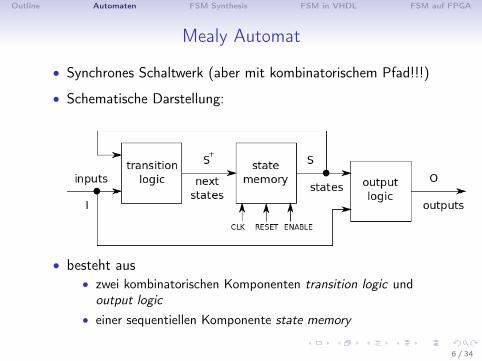
• Synchrones Schaltwerk (aber mit kombinatorischem Pfad!!!)
• Schematische Darstellung:
• besteht aus• zwei kombinatorischen Komponenten transition logic und
output logic• einer sequentiellen Komponente state memory
6 / 34
Outline Automaten FSM Synthesis FSM in VHDL FSM auf FPGA
Mealy Automat
• Folgezustand S+ abhängig von Eingabe und aktuellemZustand, d.h. S+ = FMealy (I , S), wie bei Moore Automat
• Ausgabe eines Mealy Automaten abhängig von FunktionO = FMoore(I , S), also neben aktuellem Zustand auch von deraktuellen Eingabe
• Ausgabe ändert sich asynchron mit Änderung der Eingabe(komb. Pfad)
→ Mealy kann zu komb. Schleifen in Gesamtschaltung führen,deshalb Moore meist bevorzugt
7 / 34
Outline Automaten FSM Synthesis FSM in VHDL FSM auf FPGA
Medvedev Automat
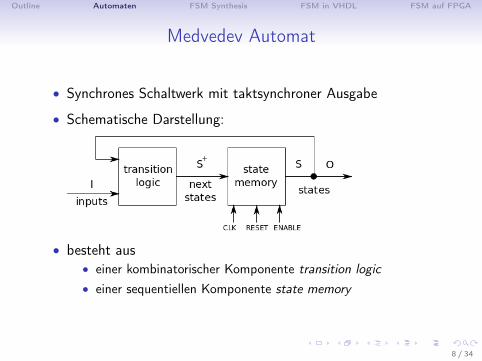
• Synchrones Schaltwerk mit taktsynchroner Ausgabe
• Schematische Darstellung:
• besteht aus• einer kombinatorischer Komponente transition logic• einer sequentiellen Komponente state memory
8 / 34

Outline Automaten FSM Synthesis FSM in VHDL FSM auf FPGA
Medvedev Automat
• Folgezustand S+ abhängig von Eingabe und aktuellemZustand, d.h. S+ = FMedvedev (I , S), wie bei Moore und Mealy
• Ausgabe eines Medvedev Automaten entspricht aktuellerZustandcodierung, d.h. O = S
• dafür ist spezielle Zustandscodierung für Medvedev erforderlich
→ überlicherweise mehr DFFs für Zustände benötigt, aberAusgabe direkt aus DFFs (taktsynchron)
9 / 34
Outline Automaten FSM Synthesis FSM in VHDL FSM auf FPGA
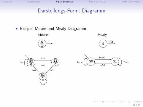
Darstellungs-Form: Diagramm
• für grafische Veranschaulichung eines Automaten
• Zustände des Automaten mit Kreisen dargestellt
• Zustandsübergänge mit Pfeilen gekennzeichnet, Bedingungenan den Pfeilen
• wichtig: Markierung des Startzustandes
• Zuweisung der Ausgaben vom Automatentyp abhängig• Moore/Medvedev: Ausgaben in den Zustandskreis• Mealy: Ausgaben an zugehörige Pfeile
10 / 34
Outline Automaten FSM Synthesis FSM in VHDL FSM auf FPGA
Darstellungs-Form: Diagramm
• Beispiel Moore und Mealy Diagramm
11 / 34
Outline Automaten FSM Synthesis FSM in VHDL FSM auf FPGA
Darstellungs-Form: Tabelle und Synthese
• Tabellen wichtig für Automaten-Synthese
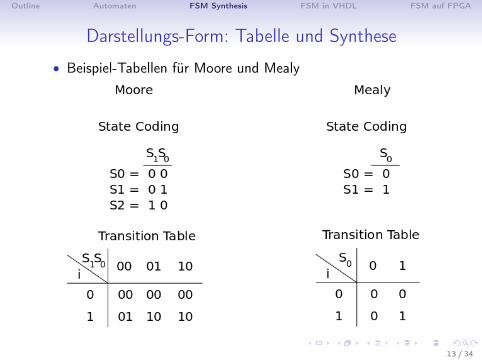
• 1.) binäre Codierung der Ein- u. Ausgaben sowie der Zustände
→ jedes Zustandsbit wird später mit einem DFF realisiert
• 2.) Aufstellen der Zustandsübergangs-Tabelle und derAusgabe-Tabelle
• 3.) Minimierung (optional)
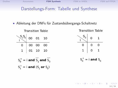
• 4.) Ableiten der DNFs für Schaltnetz-Realisierung
12 / 34
Outline Automaten FSM Synthesis FSM in VHDL FSM auf FPGA
Darstellungs-Form: Tabelle und Synthese
• Beispiel-Tabellen für Moore und Mealy
13 / 34
Outline Automaten FSM Synthesis FSM in VHDL FSM auf FPGA
Darstellungs-Form: Tabelle und Synthese
• Ableitung der DNFs für Zustandsübergangs-Schaltnetz
14 / 34

Outline Automaten FSM Synthesis FSM in VHDL FSM auf FPGA
Darstellungs-Form: Tabelle und Synthese
• Ableitung der DNFs für Ausgabe-Schaltnetz
15 / 34

Outline Automaten FSM Synthesis FSM in VHDL FSM auf FPGA
Darstellungs-Form: Tabelle und Synthese
• Resultierende Schaltungen
16 / 34
Outline Automaten FSM Synthesis FSM in VHDL FSM auf FPGA
Darstellungs-Form: Tabelle und Synthese
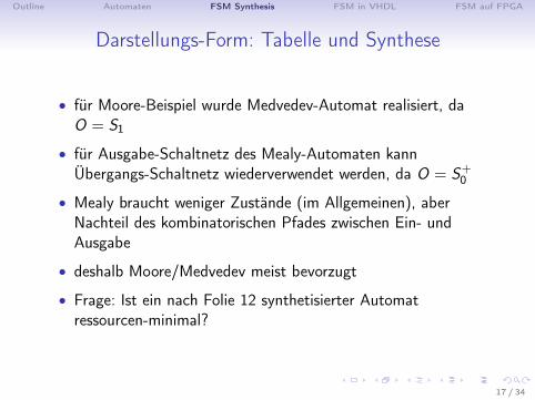
• für Moore-Beispiel wurde Medvedev-Automat realisiert, daO = S1
• für Ausgabe-Schaltnetz des Mealy-Automaten kannÜbergangs-Schaltnetz wiederverwendet werden, da O = S+
0
• Mealy braucht weniger Zustände (im Allgemeinen), aberNachteil des kombinatorischen Pfades zwischen Ein- undAusgabe
• deshalb Moore/Medvedev meist bevorzugt
• Frage: Ist ein nach Folie 12 synthetisierter Automatressourcen-minimal?
17 / 34
Outline Automaten FSM Synthesis FSM in VHDL FSM auf FPGA
FSM Beschreibungsformen in VHDL
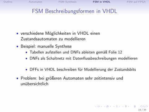
• verschiedene Möglichkeiten in VHDL einenZustandsautomaten zu modellieren
• Beispiel: manuelle Synthese• Tabellen aufstellen und DNFs ableiten gemäß Folie 12• DNFs als Schaltnetz mit Datenflussbeschreibungen modellieren
• DFFs in VHDL beschreiben für Modellierung der Zustandsbits
• Problem: bei größeren Automaten sehr zeitintensiv undunübersichtlich
18 / 34

Outline Automaten FSM Synthesis FSM in VHDL FSM auf FPGA
FSM Beschreibungsformen in VHDL
• Beschreibung in VHDL deshalb im Hilfe kombinatorischer undtaktsynchroner Prozesse
• Ein-Prozess Beschreibung• ein taktsynchroner Prozess mit Beschreibung des Automaten• Syntheseergebnis ist Netzliste mit booleschen Gattern und
DFFs• Vorteil: Ausgaben sind immer taktsynchron (zusätzliche
Register automatisch integriert)• Nachteil: unübersichtlich, keine klare Trennung zwischen
komb. und taktsynchronen Schaltungsteilen
19 / 34
Outline Automaten FSM Synthesis FSM in VHDL FSM auf FPGA
FSM Beschreibungsformen in VHDL
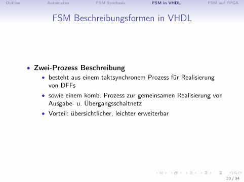
• Zwei-Prozess Beschreibung• besteht aus einem taktsynchronem Prozess für Realisierung
von DFFs• sowie einem komb. Prozess zur gemeinsamen Realisierung von
Ausgabe- u. Übergangsschaltnetz• Vorteil: übersichtlicher, leichter erweiterbar
20 / 34
Outline Automaten FSM Synthesis FSM in VHDL FSM auf FPGA
FSM Beschreibungsformen in VHDL
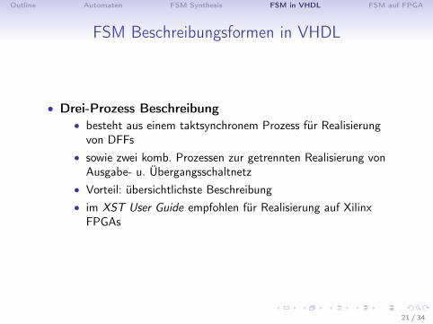
• Drei-Prozess Beschreibung• besteht aus einem taktsynchronem Prozess für Realisierung
von DFFs• sowie zwei komb. Prozessen zur getrennten Realisierung von
Ausgabe- u. Übergangsschaltnetz• Vorteil: übersichtlichste Beschreibung• im XST User Guide empfohlen für Realisierung auf Xilinx
FPGAs
21 / 34
Outline Automaten FSM Synthesis FSM in VHDL FSM auf FPGA
FSM Beschreibungsformen in VHDL
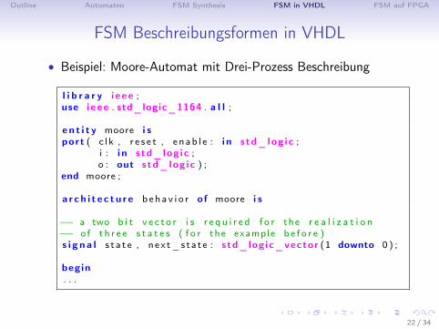
• Beispiel: Moore-Automat mit Drei-Prozess Beschreibung
l i b r a r y i eee ;use i eee . std_logic_1164 . a l l ;
en t i t y moore i sport ( c l k , r e s e t , e nab l e : i n std_log ic ;
i : i n std_log ic ;o : out std_log ic ) ;
end moore ;
a r ch i t e c t u r e b eha v i o r of moore i s
−− a two b i t v e c t o r i s r e q u i r e d f o r the r e a l i z a t i o n−− o f t h r e e s t a t e s ( f o r the example b e f o r e )s i g n a l s t a t e , nex t_s ta t e : std_logic_vector (1 downto 0 ) ;
begin. . .
22 / 34
Outline Automaten FSM Synthesis FSM in VHDL FSM auf FPGA
FSM Beschreibungsformen in VHDL
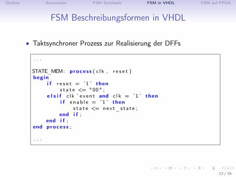
• Taktsynchroner Prozess zur Realisierung der DFFs
. . .
STATE_MEM: process ( c l k , r e s e t )begin
i f r e s e t = ’1 ’ thens t a t e <= "00" ;
e l s i f c l k ’ e ven t and c l k = ’1 ’ theni f enab l e = ’1 ’ then
s t a t e <= nex t_sta t e ;end i f ;
end i f ;end process ;
. . .
23 / 34
Outline Automaten FSM Synthesis FSM in VHDL FSM auf FPGA
FSM Beschreibungsformen in VHDL
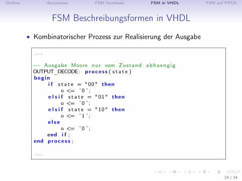
• Kombinatorischer Prozess zur Realisierung der Ausgabe
. . .
−− Ausgabe Moore nur vom Zustand abhaeng igOUTPUT_DECODE: process ( s t a t e )begin
i f s t a t e = "00" theno <= ’ 0 ’ ;
e l s i f s t a t e = "01" theno <= ’ 0 ’ ;
e l s i f s t a t e = "10" theno <= ’ 1 ’ ;
e l s eo <= ’ 0 ’ ;
end i f ;end process ;
. . .
24 / 34

Outline Automaten FSM Synthesis FSM in VHDL FSM auf FPGA
FSM Beschreibungsformen in VHDL• Kombinatorischer Prozess zur Realisierung derZustandsübergänge
. . .
TRANSITION_LOGIC : process ( s t a t e , i )begin
nex t_s ta t e <= s t a t e ; −− d e f a u l t to avo i d l a t c h e s
case ( s t a t e ) i swhen "00" =>
i f i = ’1 ’ thennex t_s ta t e <= "01" ;
e l s enex t_s ta t e <= "00" ;
end i f ;when "01" =>
i f i = ’1 ’ thennex t_s ta t e <= "10" ;
e l s enex t_s ta t e <= "00" ;
end i f ;. . .
25 / 34
Outline Automaten FSM Synthesis FSM in VHDL FSM auf FPGA
FSM Beschreibungsformen in VHDL
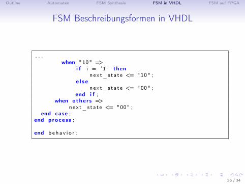
. . .when "10" =>
i f i = ’1 ’ thennex t_s ta t e <= "10" ;
e l s enex t_s ta t e <= "00" ;
end i f ;when others =>
next_sta t e <= "00" ;end case ;
end process ;
end b eha v i o r ;
26 / 34
Outline Automaten FSM Synthesis FSM in VHDL FSM auf FPGA
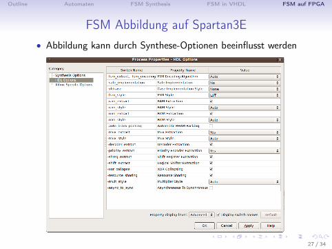
FSM Abbildung auf Spartan3E• Abbildung kann durch Synthese-Optionen beeinflusst werden
27 / 34

Outline Automaten FSM Synthesis FSM in VHDL FSM auf FPGA
FSM Abbildung auf Spartan3E
• wichtige Synthese Optionen vorallem Zustandscodierung(FSM Encoding Algorithm) und Abbildungsoption (FSMStyle)
• RTL Schematic für Moore Beispiel mit User Codierung
• Ergebnis wie erwartet (entspricht manueller Synthese)
28 / 34

Outline Automaten FSM Synthesis FSM in VHDL FSM auf FPGA
FSM Abbildung auf Spartan3E
• ABER: RTL Schematic für Moore Beispiel mit AutoCodierung
• Synthese Ergebnis verbessert → wie ???
29 / 34
Outline Automaten FSM Synthesis FSM in VHDL FSM auf FPGA
FSM Abbildung auf Spartan3E
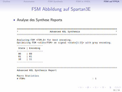
• Analyse des Synthese Reports
30 / 34
Outline Automaten FSM Synthesis FSM in VHDL FSM auf FPGA
FSM Abbildung auf Spartan3E
• Synthese-Tool ändert Zustandscodierung währendOptimierungsschritt
• anstatt S2 = ”10” wird S2 = ”11” gesetzt
• Gray Codierung führt für dieses Beispiel zu minimalemRessourcenverbrauch
• aufgrund Synthese-Tool Optimierung ist manuelle Synthesedeshalb meist überflüssig
31 / 34
Outline Automaten FSM Synthesis FSM in VHDL FSM auf FPGA
FSM Abbildung auf Spartan3E
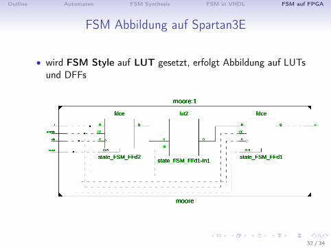
• wird FSM Style auf LUT gesetzt, erfolgt Abbildung auf LUTsund DFFs
32 / 34
Outline Automaten FSM Synthesis FSM in VHDL FSM auf FPGA
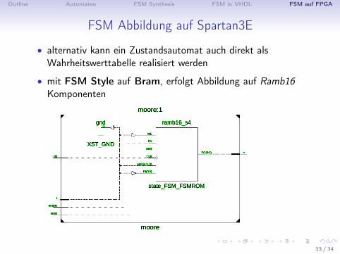
FSM Abbildung auf Spartan3E
• alternativ kann ein Zustandsautomat auch direkt alsWahrheitswerttabelle realisiert werden
• mit FSM Style auf Bram, erfolgt Abbildung auf Ramb16Komponenten
33 / 34
Outline Automaten FSM Synthesis FSM in VHDL FSM auf FPGA
Literatur
Bücher
• VHDL-Synthese, Jürgen Reichardt, Bernd Schwarz, 5. Auflage,Oldenbourg Wissenschaftsverlag GmbH, 2009, ISBN978-3-486-58987-0 Springer-Verlag Berlin Heidelberg, 1999,ISBN 3-540-64310-9
• XST User Guide, UG627 (v12.4), December, 2010
34 / 34