Embed Size (px)
Citation preview

Marching Cubes without Skinny Triangles
Carlos A. Dietrich, Carlos E. Scheidegger, Joao L. D. Comba, Luciana P. Nedeland Claudio T. Silva, Senior Member, IEEE∗†
Abstract
Most computational codes that use irregular grids de-pend on the triangle quality of the single worst triangle inthe grid: skinny triangles can lead to bad performance andnumerical instabilities. Marching Cubes is the standard iso-surface grid generation algorithm, and while most trianglesit generates are good, it almost always generates some badtriangles. Here we show how simple changes to MarchingCubes can lead to a drastically reduced number of degener-ate triangles, making it a more practical choice for isosur-face grid generation, reducing or eliminating the need andcosts of post-processing.
1. IntroductionMarching Cubes [9] is currently the most popular algo-
rithm for isosurface extraction. It is elegant, simple, fast,and robust. While the output mesh Marching Cubes gen-erates is adequate for visualization purposes, it is far frombeing suitable for use in numerical simulations. This def-ficiency arises from the degenerate triangles that MC typi-cally generates, and that, for example, a single badly-shapedtriangle can lead to ill-conditioning of an entire finite ele-ment simulation [12]. The current practice is to solve thisproblem by post-processing [1, 14], but here we present asimpler alternative. We first elucidate the causes of bad tri-angles in Marching Cubes, and then mitigate the problemwith small specific changes.
Our discussion of Marching Cubes is based on the notionof Edge Groups, recently introduced by Dietrich et al. [3].Each MC case generates up to 5 triangles, which are di-rectly encoded in a fixed table. More importantly, each tri-angle is created using vertices placed along the edges of afixed cube, and so there’s only a limited number of ways atriangle is generated. We then identify equivalent triples of
∗ Carlos A. Dietrich, Joao L. D. Comba and Luciana P. Nedel arewith the Instituto de Informatica, UFRGS, Brazil, E-mail: [cadiet-rich,comba,nedel]@inf.ufrgs.br.
† Carlos E. Scheidegger and Claudio T. Silva are with the ScientificComputing and Imaging Institute, University of Utah, USA, E-mail:[cscheid,csilva]@sci.utah.edu.
edges under the cube’s symmetries, and arrive at 8 differ-ent edge groups, illustrated in Figure 1.
Surprisingly, a single edge group is responsible for mostdegenerate triangles in MC. Some cases in the MarchingCubes table admit different triangulations, which use differ-ent edge groups. By systematically analyzing each case inthe Marching Cubes table, we generate a table that leads toimproved triangle qualities, building on our previous work[3, 4].
In the remainder of the paper, we focus on the practi-cal aspects of improving MC to generate better-shaped tri-angles. The new improved table is available at http://XXX,together with supplemental material showing more exten-sive comparisons and results.
2. Marching Cubes Tables
Given a node-centric volumetric array of data approxi-mating a scalar field f(x, y, z) : R3 → R and a scalar valuek ∈ R, MC produces a triangular surface that approximatesthe level set f(x, y, z) = k (called the isosurface). The im-plementation of Marching Cubes follows a straightforwardpipeline of actions that are executed for each cell in a givenvolume. It starts by computing the sign of each cell ver-
Figure 1. The eight Edge Groups in MarchingCubes. Every triangle in every MC configura-tion is created by one of these edge combi-nations.

tex, determined by simply comparing a given vertex’s scalarvalue with k. The signs of all vertices from a cube define aneight-bit value that identifies a particular case in MC. Thereare two pre-defined tables that are indexed by this value: anactive edge table, and a triangulation table (Figure 2).
Figure 2. Marching Cubes pipeline. The ac-tive edges encoded in the edge table nec-essarily cross the isosurface, and are illus-trated in orange. The triangulation table de-termines how to connect the vertices that lieon the active edges, creating the triangles foreach patch. Creating the entries of the trian-gulation table carefully improves the trianglequality of MC.
The active edge table identifies, for each case, whichedges of the cell are crossed by the isosurface, and there-fore which intersections must be computed. The triangula-tion table correspondingly gives the set of triangles that willbe generated from the active edges. A single MC case cangenerate up to 5 triangles. Most importantly, the encoding ofsome cases is not unique, as illustrated in Figure 3. Consid-eration of the triangulation tables is commonly given onlyup to homeomorphism of the reconstruction. In other words,any triangulation that has the same topology as the continu-ous level set that it is approximating is seen as equally good.As we will explain in the next section, the notion of EdgeGroups allows us to effectively choose triangulations thatgenerate systematically better triangles.
3. Edge Groups of Marching Cubes Cells
Our approach to improve MC is to use the quality infor-mation given by the edge groups involved in any particular
Figure 3. Two possible triangulations for thesame MC case. In some situations, differenttriangulations will cause markedly differenttriangle qualities.
triangulation, and pick the one that maximizes some crite-ria. Here, we mainly use the ratio of incircle to circumcirclenormalized to lie between zero and one; an equilateral tri-angle has maximum quality one [15]. However, the sameidea directly applies to other measures such as min-angleand max-angle, as we show in Figure 4.
Our first analysis of the impact of different edge groupscomes from plotting the probability density function of tri-angle quality for randomly selected triangles from each ofthe edge groups. In this initial model, the triangle distribu-tion is given by assuming a uniform distribution of trianglevertices along edges, and assuming that the vertex choicesare independent across edges. This gives a PDF for eachedge group, illustrated in Figure 4. It is clearly apparent thatedge group 2 has a qualitatively different behavior than theothers: a substantial fraction of the triangles it creates aredegenerate.
To test the robustness of the distribution assumptions foreach edge group, Dietrich et al. collected edge group statis-tics on a collection of 30 volume datasets [3]. First, theycollected edge group frequency data over isosurfaces ex-tracted from each of the 30 volumes. These are summa-rized in Figure 5. As would be expected, edge groups arenot equally probable. The second set of statistics presentsa much clearer picture. By counting the edge groups of the1000 worst triangles in each of the 30 extracted isosurfaces(presented in Figure 6), it becomes clear that edge group 2is responsible for, typically, over 60% of the worst 1000 tri-angles in any given dataset, and in some cases this num-ber is closer to 95%. Our strategy, then, is to systematicallychange the Marching Cubes tables to remove occurrencesof edge group 2.
4. Improving Marching Cubes
Edge groups motivate a simple criterion for improvingthe MC table. Dietrich et al [3] propose a re-triangulationin certain table entries to prevent edge group 2 from oc-curring. Their proposal focuses on only a few MC cases,namely case 5, 12, 11, and the complement of case 6 [8].

Figure 4. Edge Groups and their corresponding triangle quality.
Figure 5. Edge groups occurrence in 30datasets.
These changes update 96 entries of the MC table (120 en-tries if the table is constructed with the complement of case6 [8]), but still leaves 56 entries with occurences of edgegroup 2. Figure 7 shows examples where edge case 2 is re-moved. For some MC cases, however, it is not possible toremove edge group 2 by simply retriangulating the case: ev-
Figure 6. Edge groups occurrence in the 1000worst triangles of 30 datasets.
ery triangulation of these cases include an instance of edgegroup 2 (see the left column of Figure 8).
Figure 7. Reconnecting intersection verticesto remove the Edge Group 2. As describedby Dietrich et al. [3], we can remove the EdgeGroup 2 from MC cases 5 (top), 11 (middle),and the complement of case 6 (bottom). Re-moving edge group 2, in its turn, results inan improvement of the generated mesh qual-ity. The right column shows the retriangula-tion results.
4.1. Inserting a New Vertex in the Cell
As we have shown, retriangulating the intersection ver-tices cannot remove instances of edge group 2 for some MCcases. In these situations, we turn to an alternative approach.

By adding an additional vertex in the cell’s center and con-necting it to the intersection vertices of active edges, weremove edge groups entirely from the Marching Cubes ta-ble. The resulting triangulations are illustrated in Figure 8.A similar approach is used in contexts as diverse as dualMC meshes [11] and MC mesh simplification [10], but herewe emphasize its impact in connection to MC mesh qual-ity. Additionally, the implementation of this change is quitestraightforward and requires only small changes to the MCcode.
Figure 8. Placing a new vertex in the mid-dle of the cell to remove the Edge Group 2.The retriangulation of the intersection ver-tices with help of an additional vertex allowsthe removing of the Edge Group 2 in MCcases 9 (up row) and the complement of thecase 3 (bottom row).
To get an idea for the quality improvement created byadding an extra vertex, we note that the new configurationusing the cell center can be seen as an additional edge groupwith only two edges. This single group generates all trian-gles shown in the right column of Figure 8. More impor-tantly, its quality histogram is comparable to the best edgegroups of the cubic cell.
The position of the new vertex in the cell is dependenton the MC case. The center of the cell can be a good choicefor MC case 9, illustrated in the first row of Figure 8. In thiscase, a new triangulation with a vertex in the center of thecell will be close to the original MC triangulation. On theother hand, a new triangulation with a vertex in the centerof the cell can result in artifacts in the complement of MCcase 3. The artifacts are visible in situations where all in-tersection vertices are close to the negative vertices of thecell (blue vertices in Figure 8), in which the distance of thenew vertex to the isosurface is maximum. To alleviate thisproblem, the new vertex is placed along one of the edges ofthe original MC triangulation, that is, in the middle of thelongest edge of the triangulation. This guarantees that the
new triangulation is close to the original triangulation gen-erated by MC.
These changes in the edge table improve the triangula-tion quality. However, most of the value comes from thesynergy the new table has with the change to MC we willdescribe in the next section. Together, these two changes aresuch that the triangles generated by the MC suggested com-pare favorably to the state of the art.
Figure 9. (Left) The Edge Group resultantfrom the retriangulation of cases 9 and thecomplement of case 3, which generates alltriangles of Figure 8. (Right) The quality his-togram of the triangles generated by the newEdge Group.
4.2. Transforming active edges
The second change to MC consists of perturbing theactive edges on which intersection vertices are computed.The two edge endpoints are moved (by a small amount) in-side the volume, and then the computation of the edge ver-tex proceeds as normal. Dietrich et al’s Macet (“MarchingCubes with Edge Transformations) [4] adds two new inter-mediate steps to the MC pipeline, as described in Figure 10.The edge transformation step alters the positions of eachedge extreme along the gradient or tangent directions (Fig-ure 11). The second step, when necessary, displaces the in-tersection points away from edge extrema. Together, thesesteps tend to create active edges that are locally perpen-dicular to the isosurface, which leads to improved trianglequality. In order to enforce valid placement of edge end-points (i.e. not crossing the isosurface), edge transforma-tions are performed in several steps with smaller displace-ments along the proposed direction (in our experiments, weuse eight steps).
As described, the drawback of the Macet proposal is thatthey do not have a criteria to choose which edge transfor-mation to use. Instead, they perform both transformations,and do a neighborhood analysis that chooses the transfor-mation that leads to local improved triangle quality. While
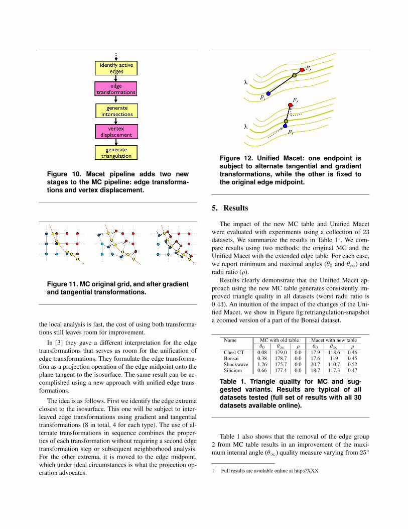
Figure 10. Macet pipeline adds two newstages to the MC pipeline: edge transforma-tions and vertex displacement.
Figure 11. MC original grid, and after gradientand tangential transformations.
the local analysis is fast, the cost of using both transforma-tions still leaves room for improvement.
In [3] they gave a different interpretation for the edgetransformations that serves as room for the unification ofedge transformations. They formulate the edge transforma-tion as a projection operation of the edge midpoint onto theplane tangent to the isosurface. The same result can be ac-complished using a new approach with unified edge trans-formations.
The idea is as follows. First we identify the edge extremaclosest to the isosurface. This one will be subject to inter-leaved edge transformations using gradient and tangentialtransformations (8 in total, 4 for each type). The use of al-ternate transformations in sequence combines the proper-ties of each transformation without requiring a second edgetransformation step or subsequent neighborhood analysis.For the other extrema, it is moved to the edge midpoint,which under ideal circumstances is what the projection op-eration advocates.
Figure 12. Unified Macet: one endpoint issubject to alternate tangential and gradienttransformations, while the other is fixed tothe original edge midpoint.
5. Results
The impact of the new MC table and Unified Macetwere evaluated with experiments using a collection of 23datasets. We summarize the results in Table 11. We com-pare results using two methods: the original MC and theUnified Macet with the extended edge table. For each case,we report minimum and maximal angles (θ0 and θ∞) andradii ratio (ρ).
Results clearly demonstrate that the Unified Macet ap-proach using the new MC table generates consistently im-proved triangle quality in all datasets (worst radii ratio is0.43). An intuition of the impact of the changes of the Uni-fied Macet, we show in Figure fig:retriangulation-snapshota zoomed version of a part of the Bonsai dataset.
Name MC with old table Macet with new tableθ0 θ∞ ρ θ0 θ∞ ρ
Chest CT 0.08 179.0 0.0 17.9 118.6 0.46Bonsai 0.38 178.7 0.0 17.6 119 0.45Shockwave 1.26 175.7 0.0 20.7 110.7 0.52Silicium 0.66 177.4 0.0 18.7 117.3 0.47
Table 1. Triangle quality for MC and sug-gested variants. Results are typical of alldatasets tested (full set of results with all 30datasets available online).
Table 1 also shows that the removal of the edge group2 from MC table results in an improvement of the maxi-mum internal angle (θ∞) quality measure varying from 25◦
1 Full results are available online at http://XXX
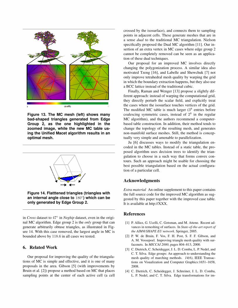
Figure 13. The MC mesh (left) shows manybad-shaped triangles generated from EdgeGroup 2, as the one highlighted in thezoomed image, while the new MC table us-ing the Unified Macet algorithm results in anoptimal mesh.
Figure 14. Flatttened triangles (triangles withan internal angle close to 180◦) which can beonly generated by Edge Group 2.
in Cross dataset to 47◦ in Neghip dataset, even in the origi-nal MC algorithm. Edge group 2 is the only group that cangenerate arbitrarily obtuse triangles, as illustrated in Fig-ure 14. With this case removed, the largest angle in MC isbounded above by 118.6 in all cases we tested.
6. Related Work
Our proposal for improving the quality of the triangula-tions of MC is simple and effective, and it is one of manyproposals in the area. Gibson [5] (with improvements byBruin et al. [2]) propose a method based on MC that placessampling points at the center of each active cell (a cell
crossed by the isosurface), and connects them to samplingpoints in adjacent cells. These generate meshes that are ina sense dual to the traditional MC triangulation. Nielsonspecifically proposed the Dual MC algorithm [11]. Our in-sertion of an extra vertex in MC cases where edge group 2cannot be completely removed can be seen as an applica-tion of these dual techniques.
Our proposal for an improved MC involves directlychanging the polygonization process. A similar idea alsomotivated Tzeng [16], and Labelle and Shewchuk [7] notonly improve tetrahedral mesh quality by warping the gridin which the boundary extraction happens, but they also usea BCC lattice instead of the traditional cubic.
Finally, Raman and Wenger [13] propose a slightly dif-ferent approach: instead of warping the computational grid,they directly perturb the scalar field, and explicitly treatthe cases where the isosurface touches vertices of the grid.The modified MC table is much larger (38 entries beforecoalescing symmetric cases, instead of 28 in the regularMC algorithm), and the authors recommend a computer-based table construction. In addition, their method tends tochange the topology of the resulting mesh, and generatesnon-manifold surface meshes. Still, the method is concep-tually very simple and amenable to parallelization.
Ju [6] discusses ways to modify the triangulation en-coded in the MC tables. Instead of a static table, the pro-posed algorithm uses decision trees to identify the trian-gulation to choose in a such way that forms convex con-tours. Such an approach might be usable for choosing thebest possible triangulation based on the actual configura-tion of a particular cell.
Acknowledgments
Extra material An online supplement to this paper containsthe full source code for the improved MC algorithm as sug-gested by this paper together with the improved case table.It is available at http://XXX.
References
[1] P. Alliez, G. Ucelli, C. Gotsman, and M. Attene. Recent ad-vances in remeshing of surfaces. In State-of-the-art report ofthe AIM@SHAPE EU network. Springer, 2005.
[2] P. W. de Bruin, F. Vos, F. H. Post, S. F. F. Gibson, andA. M. Vossepoel. Improving triangle mesh quality with sur-facenets. In MICCAI 2000, pages 804–813, 2000.
[3] C. Dietrich, C. Scheidegger, J. L. D. Comba, L. P. Nedel, andC. T. Silva. Edge groups: An approach to understanding themesh quality of marching methods. 14(6), IEEE Transac-tions on Visualization and Computer Graphics:1651–1658,2008.
[4] C. Dietrich, C. Scheidegger, J. Schreiner, J. L. D. Comba,L. P. Nedel, and C. T. Silva. Edge transformations for im-

proving mesh quality of marching cubes. IEEE Transac-tions On Visualization and Computer Graphics, 15(1):150–159, 2009.
[5] S. F. F. Gibson. Constrained elastic surface nets: Generatingsmooth surfaces from binary segmented data. In MICCAI’98: Proceedings of the First International Conference onMedical Image Computing and Computer-Assisted Interven-tion, pages 888–898, London, UK, 1998. Springer-Verlag.
[6] T. Ju, S. Schaefer, and J. Warren. Convex contouring of vol-umetric data. The Visual Computer, 19(7-8), 2003.
[7] F. Labelle and J. R. Shewchuk. Isosurface stuffing: fast tetra-hedral meshes with good dihedral angles. ACM Transactionson Graphics, 26(3):57:1–57:10, 2007.
[8] T. Lewiner, H. Lopes, A. W. Vieira, and G. Tavares. Effi-cient implementation of marching cubes’ cases with topo-logical guarantees. Journal of Graphics Tools, 8(2):1–15,2003.
[9] W. E. Lorensen and H. E. Cline. Marching cubes: A high res-olution 3d surface construction algorithm. In SIGGRAPH’87: Proceedings of the 14th annual conference on Com-puter graphics and interactive techniques, pages 163–169,New York, NY, USA, 1987. ACM Press.
[10] C. Montani, R. Scateni, and R. Scopigno. Discretized march-ing cubes. In VIS ’94: Proceedings of the conference on Vi-sualization ’94, pages 281–287, Los Alamitos, CA, USA,1994. IEEE Computer Society Press.
[11] G. M. Nielson. Dual marching cubes. In VIS ’04: Proceed-ings of the conference on Visualization ’04, pages 489–496,Washington, DC, USA, 2004. IEEE Computer Society.
[12] P. P. Pebay and T. J. Baker. A comparison of triangle qualitymeasures. In 10th International Meshing Roundtable, pages327–340, 2001.
[13] S. Raman and R. Wenger. Quality isosurface mesh genera-tion using an extended marching cubes lookup table. Com-puter Graphics Forum, 27(3):791–798, 2008.
[14] J. Schreiner, C. Scheidegger, and C. Silva. High-qualityextraction of isosurfaces from regular and irregular grids.IEEE Transactions on Visualization and Computer Graph-ics, 12(5):1205–1212, 2006.
[15] J. R. Shewchuk. What is a good linear element? - interpo-lation, conditioning, and quality measures. In 11th Interna-tional Meshing Roundtable, pages 115–126, 2002.
[16] L. Tzeng. Warping cubes: Better triangles from marchingcubes. In European Workshop on Computational Geometry,2004.


![GPU-accelerated data expansion for the Marching Cubes ... · Extract iso-surface via Marching Cubes Scalar field is sampled over 3D grid Marching Cubes [Lorensen87] —Marches through](https://img.dokumen.tips/doc/110x75/5f59a4a397733378820cfae2/gpu-accelerated-data-expansion-for-the-marching-cubes-extract-iso-surface-via.jpg)