Embed Size (px)
Citation preview
DELIVERABLE 2.4 MARANDA - Grantagreement no: 735717
MARANDA – Marine applicationof a new fuel cell powertrainvalidated in demanding arcticconditionsGrant agreement no: 735717D2.4 Preliminary safety analysisfor integrated fuel cell system andhydrogen storageAuthors: Minna Nissilä, Antti Pohjoranta, Jari Ihonen
Confidentiality:Submission date:Revision:
Public3.11.2017-
MARANDA - Grant agreement no:735717 D2.4
1 (13)
Report’s title
D2.4 Preliminary safety analysis for integrated fuel cell system and hydrogen storageCustomer, contact person, address Order reference
Lionel Boillot, FCH JU Grant agreement no:735717
Project name Project number/Short name
Marine application of a new fuel cell powertrain validated indemanding arctic conditions
MARANDA
Author(s) Pages
VTT: Minna Nissilä, Antti Pohjoranta, Jari Ihonen 13 pages
Summary
In the MARANDA EU project, a 165 kW (AC) power scale proton exchange membrane (PEM)fuel cell (FC) system is installed on-board the Aranda naval research vessel. Attached to thefuel cell system there will be a hydrogen (H2) fuel storage (350 bar) and dispensing system.
The IGF Code entered into force in the beginning of 2017, and it is mandatory for ships fueledby gases or other low-flashpoint fuels. The current version of the IGF Code includes detailedregulations to meet the functional requirements only for natural gas as fuel and internalcombustion engine as fuel consumer.
Until regulations for other low-flashpoint fuels will be added to the IGF Code, compliance withthe functional requirements of the IGF Code must be demonstrated through alternative design.The main principle of the alternative design is that design solution deviating from prescriptiveregulations/rules may be approved provided it is demonstrated to be at least as effective andsafe as that required by the regulations.
Risk assessment is an essential part of alternative design procedure and its approval. Thisdeliverable introduces the set requirements and existing guidelines for risk assessmentconcerning use of fuel cell and hydrogen systems in marine use. Plan for preliminary riskanalysis and risk assessment for research vessel Aranda’s fuel cell system is presented.
Confidentiality Public
MARANDA - Grant agreement no:735717 D2.4
2 (13)
Deliverable 2.4 2MARANDA, H2020 FCH JU project no. 735717
Contents1. Introduction ...................................................................................................................... 3
2. Requirements and approval procedure for integrated fuel cell system and hydrogenstorage on-board a ship ................................................................................................... 3
2.1 IMO Conventions and Codes ................................................................................... 32.1.1 SOLAS Convention ..................................................................................... 32.1.2 International Code of safety for ships using gases or other low-flashpoint
fuels (IGF Code) .......................................................................................... 42.2 Alternative design and arrangements ...................................................................... 5
2.2.1 IMO guidelines for alternative design ........................................................... 52.2.2 Other guidelines for IGF Code and alternative design.................................. 7
3. Preliminary design of research vessel Aranda’s fuel cell and hydrogen storage system .. 7
4. Alternative design and approval process for Aranda’s fuel cell plant and hydrogenstorage ............................................................................................................................ 8
5. Plan for preliminary risk analysis and assessment ......................................................... 10
5.1 Definition of the approval basis .............................................................................. 105.2 Steps for preliminary risk analysis and assessment ............................................... 10
5.2.1 Hazard identification .................................................................................. 105.2.2 Consequence and likelihood analyses ....................................................... 105.2.3 Risk analysis and assessment ................................................................... 125.2.4 Documentation .......................................................................................... 12
6. References .................................................................................................................... 13

Deliverable 2.4 3MARANDA, H2020 FCH JU project no. 735717
1. Introduction
In the MARANDA EU project, a 165 kW (AC) power scale proton exchange membrane (PEM)fuel cell (FC) system is installed on-board the Aranda naval research vessel. Attached to thefuel cell system there will be a hydrogen (H2) fuel storage (350 bar) and dispensing system.Together these systems will comprise a complete hydrogen-fueled PEMFC power plant, whichcan supply power to the Aranda electricity system, for example during research operationwhen minimal emissions and vibration levels on the ship are desired to guaranteemeasurement quality.
Both of the subsystems - the PEMFC system and the H2 storage system - are installed in 10-foot sea containers, attached on the deck of Aranda. The H2 storage system can be detachedfrom the fuel cell system as well as from the ship, and be lifted to/from shore by using Aranda’sown lift crane. The purpose is to enable re-filling of the H2 storage in a maximal variety oflocations and in particular, at standard 350 bar automotive hydrogen refueling stations (HRS).
As Aranda is an ice-going vessel, the ship and the fuel cell plant on-board will be subject tothe harshest marine and winter conditions during its operation. Whatever the conditions, thesafety of the equipment and especially the personnel (and other people) on-board must beguaranteed at all times. To this end, dedicated safety considerations, abiding to the normalsea-going vessel design and classification processes shall be undertaken. Furthermore, aspart of the classification process of the Aranda ship, also the fuel cell plant shall be put intoclass by the class authority DNV GL.
Because the MARANDA fuel cell plant is not a critical/single power source of the Arandavessel, the requirements for operative reliability - typically a substantial part of marine powersystem safety - may be relaxed. Nevertheless, as the fuel cell system and the hydrogen fuelstorage are systems containing highly flammable hydrogen gas, particular safety proceduresmust be followed in the design and construction of these systems.
2. Requirements and approval procedure for integrated fuel cellsystem and hydrogen storage on-board a ship
2.1 IMO Conventions and Codes
2.1.1 SOLAS Convention
International Convention for the Safety of Life at Sea (SOLAS) is the most important of allinternational treaties concerning the safety of merchant ships. The Convention in force todayis referred to as SOLAS (1974), as amended. The main objective of the SOLAS Conventionis to specify minimum standards for the construction, equipment and operation of ships,compatible with their safety.
SOLAS (1974) contains prescriptive requirements concerning e.g. structure, subdivision andstability, machinery and electrical installations (Chapter II-1), fire protection, fire detection andfire extinction (Chapter II-2), life-saving appliances and arrangements (Chapter III). FlagStates are responsible for ensuring that ships under their flag comply with its requirements.
Deliverable 2.4 4MARANDA, H2020 FCH JU project no. 735717
2.1.2 International Code of safety for ships using gases or other low-flashpointfuels (IGF Code)
The IGF Code was adopted in 2015 and it entered into force 1 January 2017. It is mandatoryfor ships fueled by gases or other low-flashpoint fuels under the International Convention forthe Safety of Life at Sea, SOLAS (IMO 2015 a). The purpose of the IGF Code is to provide aninternational standard for ships using low-flashpoint fuel, other than ships covered by the IGCCode (Code of the Construction and Equipment of Ships Carrying Liquefied Gases in Bulk).
The goal of the IGF Code (IMO 2015 b) is to provide for safe and environmentally friendlydesign, construction and operation of ships and in particular, their installations of systems forpropulsion machinery, auxiliary power generation machinery and/or other purpose machineryusing gas or low-flashpoint fuel as fuel.
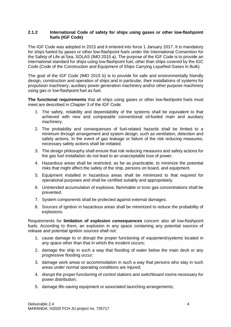
The functional requirements that all ships using gases or other low-flashpoint fuels mustmeet are described in Chapter 3 of the IGF Code:
1. The safety, reliability and dependability of the systems shall be equivalent to thatachieved with new and comparable conventional oil-fueled main and auxiliarymachinery.
2. The probability and consequences of fuel-related hazards shall be limited to aminimum through arrangement and system design, such as ventilation, detection andsafety actions. In the event of gas leakage or failure of the risk reducing measures,necessary safety actions shall be initiated.
3. The design philosophy shall ensure that risk reducing measures and safety actions forthe gas fuel installation do not lead to an unacceptable loss of power.
4. Hazardous areas shall be restricted, as far as practicable, to minimize the potentialrisks that might affect the safety of the ship, persons on board, and equipment.
5. Equipment installed in hazardous areas shall be minimized to that required foroperational purposes and shall be certified suitably and appropriately.
6. Unintended accumulation of explosive, flammable or toxic gas concentrations shall beprevented.
7. System components shall be protected against external damages.
8. Sources of ignition in hazardous areas shall be minimized to reduce the probability ofexplosions.
Requirements for limitation of explosion consequences concern also all low-flashpointfuels. According to them, an explosion in any space containing any potential sources ofrelease and potential ignition sources shall not:
1. cause damage to or disrupt the proper functioning of equipment/systems located inany space other than that in which the incident occurs;
2. damage the ship in such a way that flooding of water below the main deck or anyprogressive flooding occur;
3. damage work areas or accommodation in such a way that persons who stay in suchareas under normal operating conditions are injured;
4. disrupt the proper functioning of control stations and switchboard rooms necessary forpower distribution;
5. damage life-saving equipment or associated launching arrangements;

Deliverable 2.4 5MARANDA, H2020 FCH JU project no. 735717
6. disrupt the proper functioning of firefighting equipment located outside the explosion-damaged space;
7. affect other areas of the ship in such a way that chain reactions involving, inter alia,cargo, gas and bunker oil may arise; or
8. prevent persons’ access to life-saving appliances or impede escape routes.
The current version of the IGF Code includes detailed regulations to meet the functionalrequirements only for natural gas fuel. Regulations for other low-flashpoint fuels will be addedto the IGF Code as the International Maritime Organization (IMO) develops them. In themeantime, for other low-flashpoint fuels, compliance with the functional requirements of theIGF Code must be demonstrated through alternative design.
2.2 Alternative design and arrangements
Traditional prescriptive regulatory approach, based on experience, is not adapted tobreakthrough innovations. That is why SOLAS regulations II-1/55 and III/38 concerningalternative design were adopted in 2006.
Alternative design and arrangements mean measures, which deviate from the prescriptiverequirement(s) of SOLAS chapters II-1 or III, but are suitable to satisfy the intent of thatchapter. The term includes a wide range of measures, including alternative shipboardstructures and systems based on novel or unique designs, as well as traditional shipboardstructures and systems that are installed in alternative arrangements or configurations. (IMO2006).
The main principle is that design solution deviating from prescriptive regulations/rules may beapproved provided it is demonstrated to be at least as effective and safe as that required bythe regulations. The approval of an equivalent design is in the hands of the Flag State and theapproval should be reported to IMO by the approval authority.
2.2.1 IMO guidelines for alternative design
In many IMO conventions, there are provisions for acceptance of alternatives and/orequivalents to prescriptive requirements in many areas of ship design and construction. In thiscontext, IMO has issued guidelines e.g.
· Guidelines on alternative design and arrangements for fire safety (MSC/Circ.1002,2001)
· Guidelines on alternative design and arrangements for SOLAS chapters II-1 and III(MSC.1/Circ.1212, 2006).
These Guidelines are intended for application of fire safety engineering design and safeengineering design to provide technical justification for alternative design and arrangements.The Guidelines are not intended to serve as a stand-alone document, but should be used inconjunction with the appropriate engineering design guides and other literature.
According to the Guidelines MSC.1/Circ.1212 the engineering analysis used to show that thealternative design and arrangements provide the equivalent level of safety to the prescriptiverequirements of SOLAS chapters II-1, II-2 and III should follow an established approach tosafety design. This approach should be based on sound science and engineering practiceincorporating widely accepted methods, empirical data, calculations, correlations andcomputer models as contained in engineering textbooks and technical literature.

Deliverable 2.4 6MARANDA, H2020 FCH JU project no. 735717
In 2013, the Maritime Safety Committee approved the Guidelines for the approval ofalternatives and equivalents as provided for in various IMO instruments (MSC.1/Circ. 1455,2013). The Guidelines provide a consistent process (figure 1) for the coordination, review andapproval of alternatives and equivalents with regard to ship and system design as allowed bythe SOLAS Convention and other mandatory IMO instruments.
Figure 1. Process for alternative design approval according to MSC.1/Circ. 1455 (IMO2013a). (Numbers in figure refer to chapters in MSC.1/Circ. 1455)
Deliverable 2.4 7MARANDA, H2020 FCH JU project no. 735717
The Guidelines MSC.1/Circ. 1455 are intended for use of both Administrations and Submitterswhen dealing with an approval request for an alternative and/or equivalent design. Theprocess in figure 1 describes the procedure for obtaining and maintaining approval of analternative and/or equivalency taking into account the Submitter and the Administration.
The details performed in each phase of the process may vary on a case-by-case basisdepending on the design being considered. However, the basic process should be generallyapplicable to the approval of most alternatives and/or equivalencies. Guidelines MSC.1/Circ.1455 contain detailed instructions for each phase of the process.
2.2.2 Other guidelines for IGF Code and alternative design
In addition to IMO, also other organisations like Classification Societies have published rulesand guidelines for fuel cells, IGF Code and alternative design and arrangements e.g. ABS(2010), DNVGL (2017), GL (2009), IACS (2016), Lloyd's Register (2016) and Lloyd's Register(2017).
3. Preliminary design of research vessel Aranda’s fuel cell andhydrogen storage system
Preliminary design of the fuel cell and hydrogen subsystems, including their process diagramsare presented in Deliverable 2.1 Specification report. This preliminary design will be updatedand modified based on the findings of the systems’ safety evaluation work.
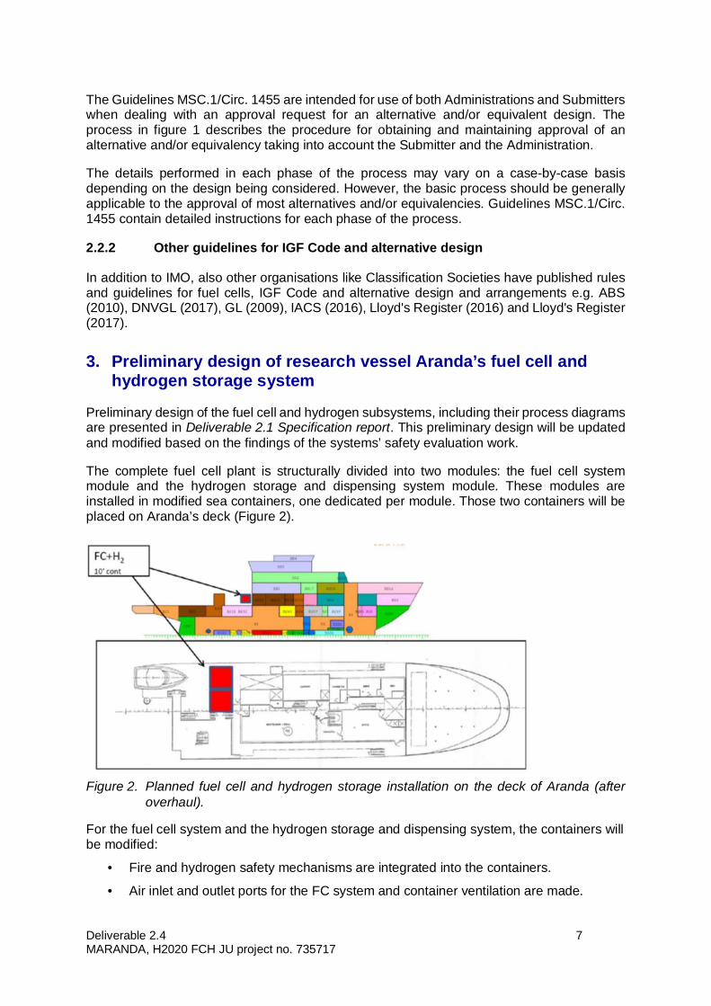
The complete fuel cell plant is structurally divided into two modules: the fuel cell systemmodule and the hydrogen storage and dispensing system module. These modules areinstalled in modified sea containers, one dedicated per module. Those two containers will beplaced on Aranda’s deck (Figure 2).
Figure 2. Planned fuel cell and hydrogen storage installation on the deck of Aranda (afteroverhaul).
For the fuel cell system and the hydrogen storage and dispensing system, the containers willbe modified:
· Fire and hydrogen safety mechanisms are integrated into the containers.
· Air inlet and outlet ports for the FC system and container ventilation are made.
Deliverable 2.4 8MARANDA, H2020 FCH JU project no. 735717
· Fire-insulated through-holes for hydrogen and data signal passage between thecontainers are made
· Necessary utility power inlet ports are included in both containers.
The general safety philosophy of the fuel cell system as well as the hydrogen storage followsan emergency shutdown (ESD) approach meaning the system is fully powered off if hydrogenis detected elsewhere than where it is supposed to be. This is feasible, because the FC plantis not an operationally critical power source of the Aranda vessel.
During its operation, the fuel cell system is ventilated to ensure hydrogen concentrationremains within safe limits even in case of leakage. Hydrogen concentration of the air iscontinuously monitored in the ventilated fuel cell space as well as in the ventilation air duct.When not in operation, the fuel cell system is always purged of hydrogen gas. Therefore, thefuel cell system is considered a safe zone when not in operation (hazardous zone 1 when inoperation).
The hydrogen storage system is always considered hazardous zone 1 and continuous ATEX-rated, redundant ventilation and hydrogen monitoring are therefore applied to this part. Inaddition, explosion relief hatches for controlled impact direction in case of pressure build upor even explosion are installed to the hydrogen storage module container.
On behalf of safety regarding fire outside the containers, A60 level fire insulation is installedwhere necessary. Furthermore, thermally activated pressure relief devices (TPRDs) areincluded in the hydrogen storage system to assure a controlled hydrogen release in the caseof long-enduring fire. For the case of fire inside systems, the amount of flammable material iskept to minimum. Smoke detectors, fire dampers at ventilation air inlets and a fire extinctionsystem are included in the fuel cell system as well as the hydrogen storage system.
4. Alternative design and approval process for Aranda’s fuel cellplant and hydrogen storage
As the amendment to the IGF Code regarding fuel cells is not yet approved, the complianceof Aranda’s fuel cell system with the functional requirements of the IGF Code must bedemonstrated through alternative design (see chapter 2). The approval procedure for thealternative design is presented in chapter 2.2 figure 1 (IMO 2013 a).
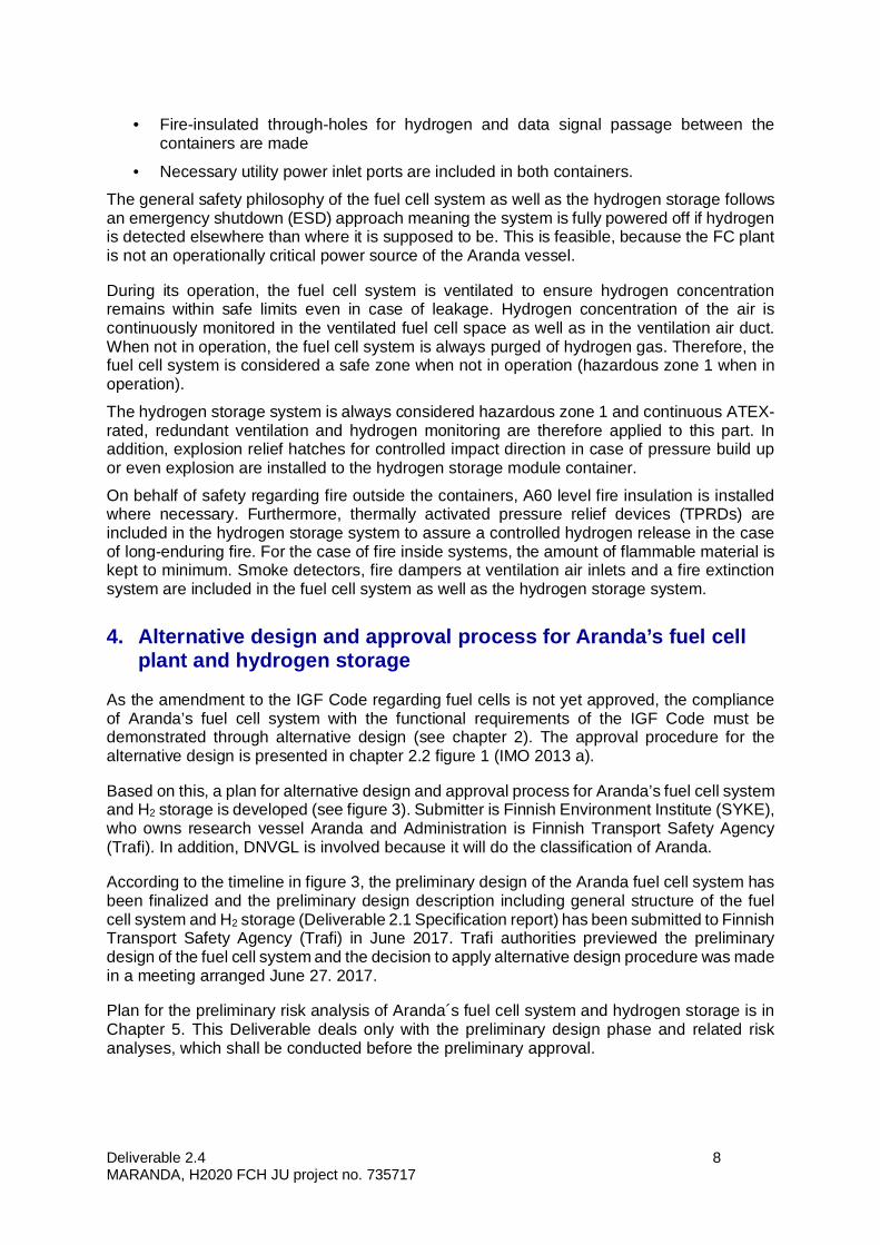
Based on this, a plan for alternative design and approval process for Aranda’s fuel cell systemand H2 storage is developed (see figure 3). Submitter is Finnish Environment Institute (SYKE),who owns research vessel Aranda and Administration is Finnish Transport Safety Agency(Trafi). In addition, DNVGL is involved because it will do the classification of Aranda.
According to the timeline in figure 3, the preliminary design of the Aranda fuel cell system hasbeen finalized and the preliminary design description including general structure of the fuelcell system and H2 storage (Deliverable 2.1 Specification report) has been submitted to FinnishTransport Safety Agency (Trafi) in June 2017. Trafi authorities previewed the preliminarydesign of the fuel cell system and the decision to apply alternative design procedure was madein a meeting arranged June 27. 2017.
Plan for the preliminary risk analysis of Aranda´s fuel cell system and hydrogen storage is inChapter 5. This Deliverable deals only with the preliminary design phase and related riskanalyses, which shall be conducted before the preliminary approval.
Deliverable 2.4 9MARANDA, H2020 FCH JU project no. 735717
Figure 3. Plan for alternative design and approval process for Aranda’s fuel cell system and H2 storage.
Deliverable 2.4 10MARANDA, H2020 FCH JU project no. 735717
5. Plan for preliminary risk analysis and assessment
5.1 Definition of the approval basis
According to Guidelines for the approval of alternatives and equivalents as provided for invarious IMO instruments (IMO 2013 a) the phase following the preliminary design preview isdefinition of the approval basis. The Submitter and the Administration will agree on theapproval basis and on the evaluation criteria.
The approval basis was discussed in the end of October 2017. Participants from FinnishEnvironment Institute (SYKE), VTT, Finnish Transport Safety Agency (Trafi) and DNVGL tookpart this meeting.
5.2 Steps for preliminary risk analysis and assessment
IMO guidelines (IMO 2006, IMO 2013 a) contain general requirements and procedures forpreliminary risk analysis. The steps defined are 1) identification of hazards 2) enumeration ofhazards 3) selection of hazards for more detailed analysis 4) specification of designaccident/casualty scenarios.
IACS (International Association of Classification Societies) produces recommendations andguidelines related to adopted resolutions that are not necessarily matters of class but whichIACS considers would be helpful to offer some advice to the marine industry. One of thoserecommendations is “Recommendation 146 Risk assessment as required by the IGF Code”(IACS 2016). This recommendation complies with the general requirements of the IMOguidelines. IACS Recommendation 146 will be used as basis for Aranda’s risk assessment asthis recommendation is specifically intended to be used in risk assessment required by theIGF Code.
5.2.1 Hazard identification
The aim is systematically identify unwanted events that could result in, for example, majorinjuries or fatality, damage to the environment, and/or loss of structural strength or integrity ofthe ship. For Aranda’s hazard identification, the entirety of the fuel cell power plant will bedivided to appropriate parts. Apparent parts would be the fuel cell system module and thehydrogen storage and dispensing system module. All conceivable and relevant hazards ofthose modules shall be identified.
Hazard identification will be done in a structured brainstorming with the purpose of identifyingall relevant hazards, their causes, possible consequences and mitigating measures alreadyincluded in the design. The identification work should be done with an open mind and thepeople taking part in it should have expertise in various fields (fuel cells, chemicals, materials,consequences of leaks, flammability risks etc.). There are guidewords and check-list, whichcan be used to help hazard identification (IMO 2006, IACS 2016). The results of theidentification phase shall be documented.
Hazard identification session or sessions will take place in November-December 2017.
5.2.2 Consequence and likelihood analyses
For each identified cause and following hazard, an estimation of potential consequences shallbe made. The harmful consequences can be, for example, major injuries, single and multiplefatalities, adverse environmental impact and damage sufficient to compromise safe
Deliverable 2.4 11MARANDA, H2020 FCH JU project no. 735717
operations. The risk analysis team can estimate the potential consequences by usingjudgement and reference to: (a) the fuel’s properties/hazards; (b) the release location; (c)dispersion/leak pathways; (d) location and ‘strength’ of ignition sources; (e) proximity ofvulnerable receptors; (f) generic or (if commissioned) specific fire and explosion modelling;and (f) expected effectiveness of existing/planned mitigation measures.
In addition, to estimating the potential consequences also the likelihood of occurrence of‘cause and consequence’ shall be estimated. Likelihood can be estimated by the risk analysisteam for each ‘cause-consequence’ pair or a grouping of causes with the same consequence.The estimation can be informed by reference to accident and near-miss reports, accident andequipment release data, analogy to accidents in similar or other industries and considerationof the reliability and effectiveness of mitigation measures.
It is not always apparent if the likelihood of a ‘cause-consequence’ combination is credible (i.e.reasonably foreseeable). There are guidelines, for example, in IACS Recommendation 146how to evaluate if an unwanted event may be considered credible or not.
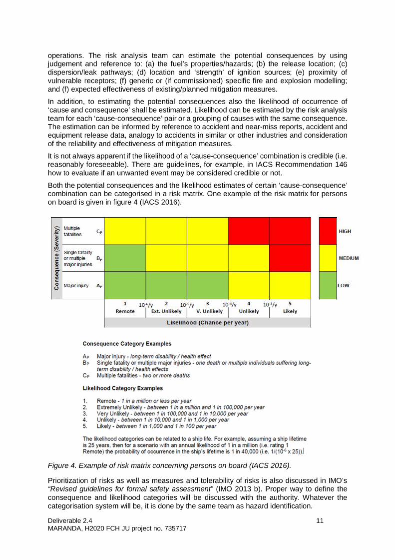
Both the potential consequences and the likelihood estimates of certain ‘cause-consequence’combination can be categorised in a risk matrix. One example of the risk matrix for personson board is given in figure 4 (IACS 2016).
Figure 4. Example of risk matrix concerning persons on board (IACS 2016).
Prioritization of risks as well as measures and tolerability of risks is also discussed in IMO’s“Revised guidelines for formal safety assessment” (IMO 2013 b). Proper way to define theconsequence and likelihood categories will be discussed with the authority. Whatever thecategorisation system will be, it is done by the same team as hazard identification.
Deliverable 2.4 12MARANDA, H2020 FCH JU project no. 735717
5.2.3 Risk analysis and assessment
Risk can be estimated by combining the consequence and likelihood categories to provide arisk rating. For example in figure 4, if a ‘cause-consequence’ pair is categorised as, say ‘Ap’,and associated ‘likelihood’ as, say ‘1’, then the risk rating is ‘Ap1’.
The estimated risk can be compared against risk criteria embedded within a risk matrix. Thematrix shows the risk rating (with respects to consequence and likelihood) and the criteriaillustrate whether the risk has been ‘mitigated as necessary’. The ratings have been defined(IACS 2016).
Green - Low Risk: The risk can be accepted as ‘mitigated as necessary’. Where practical andcost-effective good practice is to implement mitigation measures that would further reduce therisk.
Yellow - Medium Risk: The risk is tolerable and considered ‘mitigated as necessary’. Thisassumes that all reasonably practicable mitigation measures have been implemented. Thatis, additional or alternative mitigation measures have been identified and implemented unlessjudged impractical or the cost of implementation would be disproportionate to the reduction inrisk.
Red - High Risk: The risk is unacceptable and is not ‘mitigated as necessary’. Additional oralternative mitigation measures must be identified and implemented before operation, andthese must reduce the risk to medium or low.
There are no universally agreed risk rating schemes or risk criteria: there are differencesbetween governments, regulators and organisations. Therefore, prior to the commencementof the risk assessment, risk rating/criteria should be agreed with appropriate stakeholders (e.g.the Administration).
Practically, the risk rating is an indication that additional or alternative mitigation measures:
· must be provided; or
· must be considered and implemented if practical and cost effective; or
· need not be considered further, beyond accepted good practice of reducing risk wherepracticable.
The phrase ‘Mitigated as necessary’ is used in the IGF Code and means the same as thephrase ‘As Low as Reasonably Practicable’, commonly referred to as ALARP. Essentially, arisk is considered ALARP if all reasonably practicable mitigation measures have beenimplemented. This means that additional or alternative measures have been identified andimplemented unless they are demonstrated as impractical or the cost of implementation isdisproportionate to the reduction in risk.
5.2.4 Documentation
Documentation of the preliminary risk analysis and assessment of Aranda’s fuel cell andhydrogen storage system will follow the good practices described in IMO Guidelines (IMO2013a), IACS Recommendations (IACS 2016) and in standard EN 31010 Risk management. Riskassessment techniques. The aim is to conduct the preliminary risk analysis for Aranda’s fuelcell and hydrogen system by the end of February 2018.

Deliverable 2.4 13MARANDA, H2020 FCH JU project no. 735717
6. References
ABS (American Bureau of Shipping) 2004. Guidance notes on alternative design andarrangements for fire safety, updated July 2010.https://preview.eagle.org/eagleExternalPortalWEB/ShowProperty/BEA%20Repository/Rules&Guides/Current/122_AltDesign&ArrangforFireSafety/Pub122_FireSafetyGuide
DNVGL 2017. Rules for classification of ships (RU-SHIP) Part 6 (Additional class notations),Chapter 2 (Propulsion, power generation and auxiliary systems) Section 3 Fuel cellinstallations.
GL 2009. Rules for Classification and Construction, V (Analysis Techniques), 2 (RiskAnalyses) 1 Guidelines for the Analysis of Alternative Design and Arrangements.
IACS 2016. Recommendation 146. Risk assessment as required by the IGF Code.http://www.iacs.org.uk/media/4468/rectb.pdf
IMO 2006. Guidelines on alternative design and arrangements for SOLAS chapters II-1 andIII. MSC.1/Circ.1212. http://www.safedor.org/resources/Guidelines-on-alternative-designs-and-arrangements-for-SOLAS-capters-II-1-and-III-MSC-circ-1212.pdf
IMO 2013 a. Guidelines for the approval of alternatives and equivalents as provided for invarious IMO instruments. MSC.1/Circ.1455.http://www.mardep.gov.hk/en/msnote/pdf/msin1339anx1.pdf
IMO 2013 b. Revised Guidelines for Formal Safety Assessment (FSA) for use in the IMOrule-making process. MSC-MEPC.2/Circ.12. http://research.dnv.com/skj/IMO/MSC-MEPC%202_Circ%2012%20FSA%20Guidelines%20Rev%20III.pdf
IMO 2015 a. Resolution MSC.392(95) (adopted on 11 June 2015) Amendments to theInternational Convention for the Safety of Life at Sea, 1974, as amendedhttp://www.imo.org/en/KnowledgeCentre/IndexofIMOResolutions/Maritime-Safety-Committee-(MSC)/Documents/MSC.392(95).pdf
IMO 2015 b. Resolution MSC.391(95) (adopted on 11 June 2015) Adoption of theInternational Code of Safety for Ships Using Gases or Other Low-Flashpoint Fuels(IGF Code)http://www.imo.org/en/KnowledgeCentre/IndexofIMOResolutions/Maritime-Safety-Committee-(MSC)/Documents/MSC.391(95).pdf
Lloyd's Register 2016. Risk Based Designs (RBD).https://www.cdlive.lr.org/information/documents%5CShipRight%5CDesign%20and%20Construction%5CAdditional%20Design%20Procedures%5CAssessment%20of%20Risk%20Based%20Designs%20(ARBD)%5CRisk%20Based%20Designs%20May%202016%20COMPLETE.PDF
Lloyd's Register 2017. Rules and Regulations for the Classification of Ships using Gases orother Low-flashpoint Fuels.